
Abstract
A highly crystalline aliphatic segmented polyurethane (PU) elastomer with 40 wt% hard segment (HS) content, based on 1,6-hexamethylene diisocyanate and 1,4-butanediol as the HS, and a block copolymer of hexamethylene carbonate and polycaprolactone as the soft segment (SS), has been used as the matrix to prepare carbon nanofiller/PU composites by solution casting. Composite films with different loadings of solvent-exfoliated graphene (G)/nanographite, graphene oxide (GO) obtained by the so-called modified Hummers method, and acid-treated multiwalled carbon nanotubes (MWCNT) were obtained and characterised. Tensile test results show that the effectiveness of increasing PU strength follows the trend MWCNT > GO > G. The ductility reduction in all the cases is related to the large sizes of nanofillers in relation to PU hard domains and the hindrance to allow plastic flow of PU SSs by larger fillers.
Introduction
Polyurethane (PU) is one of the most versatile copolymers used to prepare tailor-made materials; 1 –3 but there are some properties, such as yield stress, tensile strength or elastic modulus, could be improved by the addition of nanosized fillers such as carbon nanotubes 4 –7 or graphene (G). 8 –10 One of the goals pursued by many researchers is to produce strong, stiff and yet tough materials. 3,4,8 Some works have endeavoured on the trial by combining PU elastomers with different nanofillers like smectic clays such as laponite 11 or montmorillonite. 12
The combination of carbon nanostructures, which display both the highest stiffness and strength of any material known to date, 13,14 with PU, which can be considered as tuneable block copolymers consisting of nanophase-separated hard segments (HSs) and soft segments (SSs), may lead to complex ternary composite systems 5 with synergetic effects on the mechanical performance of final composites 5,15,16 with stiffness and strengths analogous to high-grade thermoplastics but with extensibilities typical of elastomers and hence with very high intrinsic toughness. 8 But come to the point: which is the best carbon nanofiller as to work as a reinforcing agent?
In this work, to elucidate the differences between nanofiller type as reinforcing elements of PU, a set of composites incorporating multiwalled carbon nanotubes (MWCNT), graphene (G)/nanographite and graphene oxide (GO) were prepared by the solvent-casting approach and by the solvent exchange method 11 in the case of hydrophilic GO. Mechanical performance of the resulting composite materials is related to nanofillers structure.
Materials and methods
PU matrix
PU matrix was synthesised in our laboratory by the two-shot polymerisation approach. 17 It consists of 40 wt% HS (with a solubility parameter of δ = 23.0 J1/2 cm− 3/2) formed by 1,6-hexamethylene diisocyanate (Bayer, Desmodur H, Leverkusen, Germany) and 1,4-butanediol (Aldrich, 99% purity, Madrid, Spain). SSs (δ = 20.9 J1/2 cm− 3/2) consisted of a polydiol formed by polycaprolactone and polycarbonate blocks (Ravecarb 111, Polimeri Europa, Ravena, Italy). Details of this polyol are given elsewhere. 17
Nanofillers
Thin-MWCNT (Nanocyl 3100, Sambreville, Belgium) were purified by a strong acid treatment during 2 h, consisting of a mixture of nitric and sulphuric acid (H2SO4) in a ratio of 1:3, in a ultrasonic bath. The purification process was undergone in order to remove the remaining catalyst particles but also to introduce functional carboxylic groups onto the nanotubes surface. 18
G/nanographite sheets were obtained by solvent exfoliation of graphite (Aldrich, Graphite flakes, Madrid, Spain) 19,20 in N-methyl pyrrolidone (Panreac, 99%, Barcelona, Spain) in a ultrasonic bath (Selecta, Ultrasons-H, 940 W, Barcelona, Spain) during ∼110 h. The resulting dispersion was decanted and the supernatant was filtered and washed with acetone to obtain G powders. The evidence of effective exfoliation was acquired by Raman spectroscopy (Renishaw, InVia, excitation laser of 514 nm, Gloucestershire, UK) as an appearance of the D band (at ∼1347 cm− 1) and the broadening of the 2D band (∼2713 cm− 1; see Figure 1).
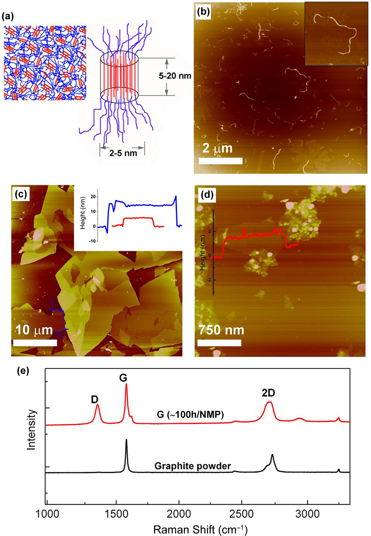
Structure of composites components. (a) Scheme of morphology and domain sizes of typical polyurethane elastomer. AFM height images of (b) MWCNT (10 µm × 10 µm), (c) G sheets (40 µm × 40 µm) and (d) GO sheets/particles (3 µm × 3 µm). In (c) and (d) profiles are shown with red and blue lines. (e) Raman spectra of graphite powder and solvent-exfoliated nanographite/graphene. MWCNT: multiwalled carbon nanotubes; G: graphene; GO: graphene oxide; AFM: atomic force microscopy. (The colour version of this article is available at http://jtc.sagepub.com.)
GO was obtained through oxidation of graphite (10 g) following the modified Hummers method, 21 extended for 15 days. GO was washed by dilution/sonication/centrifugation/decantation sequences employing first a mixture of H2SO4 (∼3 wt%) and hydrogen peroxide (∼ 0.5 wt%) for 10 cycles and then hydrochloric acid (∼3 wt%) for eight times, until no barium sulphate was observed as a precipitate when drops of barium chloride aqueous solution are added to the supernatant.
Preparation of composites
Composites were prepared using a mixture of dimethylformamide (DMF, boiling point: 165°C) and tetrahydrofuran (THF, boiling point 66°C), in a ratio of 1:1, as the solvent. This system was chosen because amide solvents are known to be good carbon nanotube dispersants, 22 while THF dissolves fairly well PU SSs and at the same time it has a low boiling point that allows an easy evaporation of the solvent from the cast composites. The preparation of composites has been explained elsewere. 5 Briefly, first the required amount of nanofiller was suspended in 6 mL of the solvent mixture and was sonicated under a high-energy sonication tip (Vibracell 75043, Newtown, USA) operated with an amplitude of 20%. Afterwards, the right amount of polymer solution (50 mg mL− 1) in the same solvent mixture was pipetted to produce a composite film of 300 mg total weight. The composite solvent mixture was sonicated again for 10 min after which the mixture was again sonicated in a low-energy sonic bath for 2 h. The solutions were then drop cast into polytetrafluoroethylene moulds and the solvent was evaporated under controlled temperature and vacuum conditions. Composites were prepared with GO by the solvent exchange method by dispersing first GO powders in 6 mL of water for 10 min with sonic tip and then 1 h in sonic bath. Then 6 mL DMF was added and the water was left to evaporate. After water evaporation, the right amount of PU solution was added and solutions were ultrasonicated for 10 min with sonic tip and 1 h into the sonic bath. Another batch of GO composites was prepared by 2-h bath ultrasonication of GO in water and 2-h bath ultrasonication of the GO/DMF/PU dispersion. The solvent evaporation cycle was the same as in all the cases.
Characterisation
Atomic force microscope (AFM, Nanoscope IIIa, Veeco, USA) was operated in the tapping mode, provided with tips of average radio of 10 nm and applying moderate forces (typically amplitude set points between 0.8 and 2 V and drive amplitudes of 50 to 500 mV). Scan rates were in the range of 0.8–1.2 Hz.
Tensile tests were performed with a constant cross head speed of 100 mm min− 1 for composites up to 40 wt% loading and with a strain rate of 1 mm min− 1 for 40 and 60 wt% G composites, with an initial cross head distance of 8.5 ± 0.5 mm in all the cases. Sample sizes were in the range of 80–140 μm in thickness and 2.5 mm in width. The equipment used (MTS insight 10, Minnesota, USA) was provided with pneumatic grips (Advantage Pneumatic Grips, MTS, Minnesota, USA) and with a load cell of 250 N. The results were averaged from a minimum of three specimens. Scanning electron microscopy images were obtained using a JEOL JSM-6400 (JEOL, Tokyo, Japan) at 20 kV of electron accelerating voltages.
Results and discussion
Figure 1(a) shows a scheme of PU nanophase morphology consisting of SS domains (blue) and HS domains (red), with sizes usually approximately between 5 and 20 nm, depending on the HS content, HS and polyol nature as well as thermal treatments or PU synthesis pathway. 23 Figure 1(b) shows an AFM height image of acid-treated MWCNT having average diameters and lengths of 12 and 740 nm, respectively. Figure 1(c) shows a 40 μm × 40 μm AFM height image of G sheets. The large surface area of these fillers is clearly seen. The inset presents the high cross-section profiles of the profiled layers, indicating that stacks of about 5 to 10 nm thick were obtained. This suggests the presence of multiple G layers in the samples. Despite their large surface and thickness solvent exfoliation seemed to have a dramatic impact on the graphitic structure of graphite stacks as could be observed by Raman spectroscopy analysis. In particular, the appearance of a strong D band at 1347 cm− 1 and the broadening of the 2D band at ∼2713 cm− 1 are the most relevant features (see Figure 1) of G spectra. These combined features are related to flakes edge effects and induced disorders into graphitic structure as well as to a relatively effective exfoliation. 8,24
Figure 1(d) presents a 3 μm × 3 μm AFM height image of GO. The presence of both spherical nanoparticles of around 25 nm diameter and GO single or bilayer sheets below them (see height profile in the inset of Figure 1(d)) is seen. It is noteworthy that the surface area of these sheets is notably smaller that that obtained by the solvent exfoliation method (shown in Figure 1(c)).
G/nanographite sheets were effectively dispersed in the DMF/THF solution giving stable dispersions and finely dispersed composites (shown in Figure 2(a) for a 12 wt% G composite), while trying to disperse GO sheets in this solution led always to partial agglomeration of the particles. After PU addition, agglomeration was delayed but badly dispersed composites were achieved after the slow evaporating cycle (shown in Figure 2(b) for an 8 wt% GO composite). For this reason, a solvent exchange method 11 was chosen in order to prepare finely dispersed GO/PU composites. This method led to much better dispersed GO/PU composites, as can be seen in Figure 2(c).
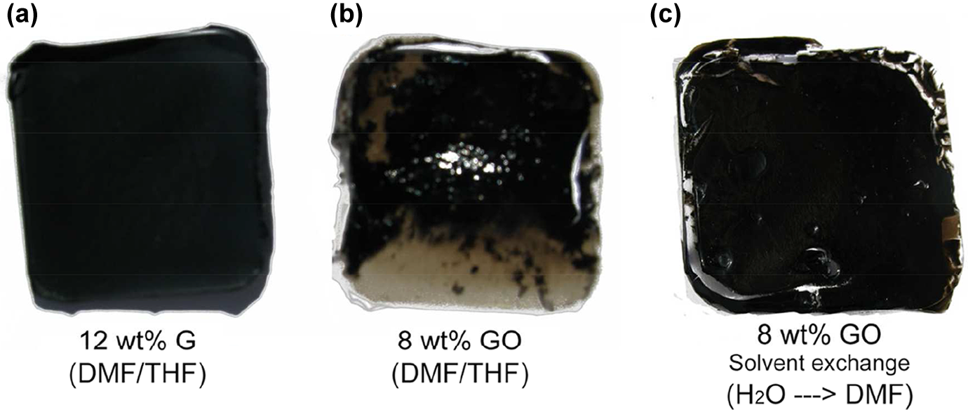
Photographs of composites with (a) G and (b) GO prepared straight in DMF/THF and (c) GO prepared by solvent exchange. GO: graphene oxide; DMF: dimethylformamide; THF: tetrahydrofuran.
Representative stress–strain curves of composites with different fillers are gathered in Figure 3 along with the representative curve of neat PU. Data of strain to failure, ε max,c, tensile strength, σ c, and tensile elastic modulus, E c, of these composites are presented in Table 1. It is seen that the best balance of reinforcing parameters (E c, σ c, ε max,c) of the fillers, regarded as indispensable to achieve tough materials, follows the order MWCNT > GO > G.
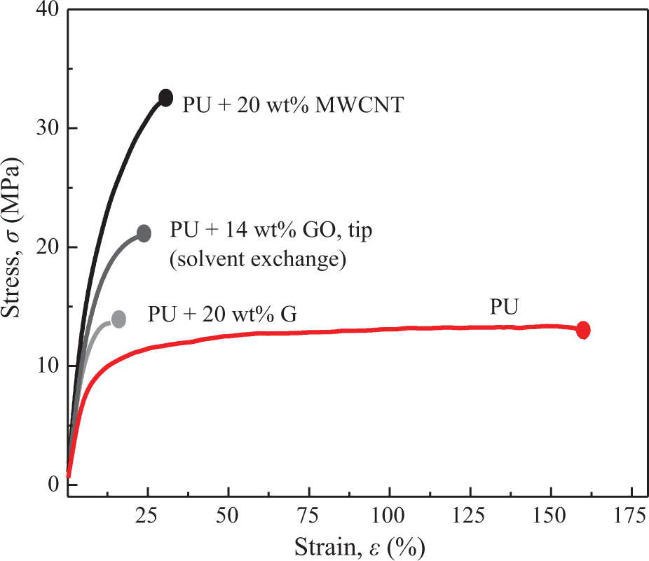
Representative stress–strain curves of composites with different fillers.
Resume of mechanical properties of composites with different fillers.
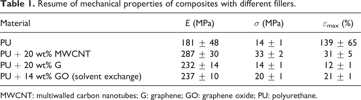
MWCNT: multiwalled carbon nanotubes; G: graphene; GO: graphene oxide; PU: polyurethane.
Figure 4 gathers tensile test results for all types of composites with a wide range of filler concentrations. Composites with GO were prepared both by tip sonication (as in the case of MWCNT and G composites) and by only bath sonication in order to avoid possible metal titanium contamination from the tip, favoured in water media. Composites strain to failure, tensile strength, and tensile elastic modulus are normalised with respect to PU values. It is clearly seen that composites prepared with MWCNT present higher strains to failure (Figure 4(a)) for all nanofiller contents than composites prepared with either G or GO (prepared by tip sonication or bath sonication only). At the same time, strength (Figure 4(b)) and modulus (Figure 4(c)) were also higher for composites containing MWCNT than with G or GO.
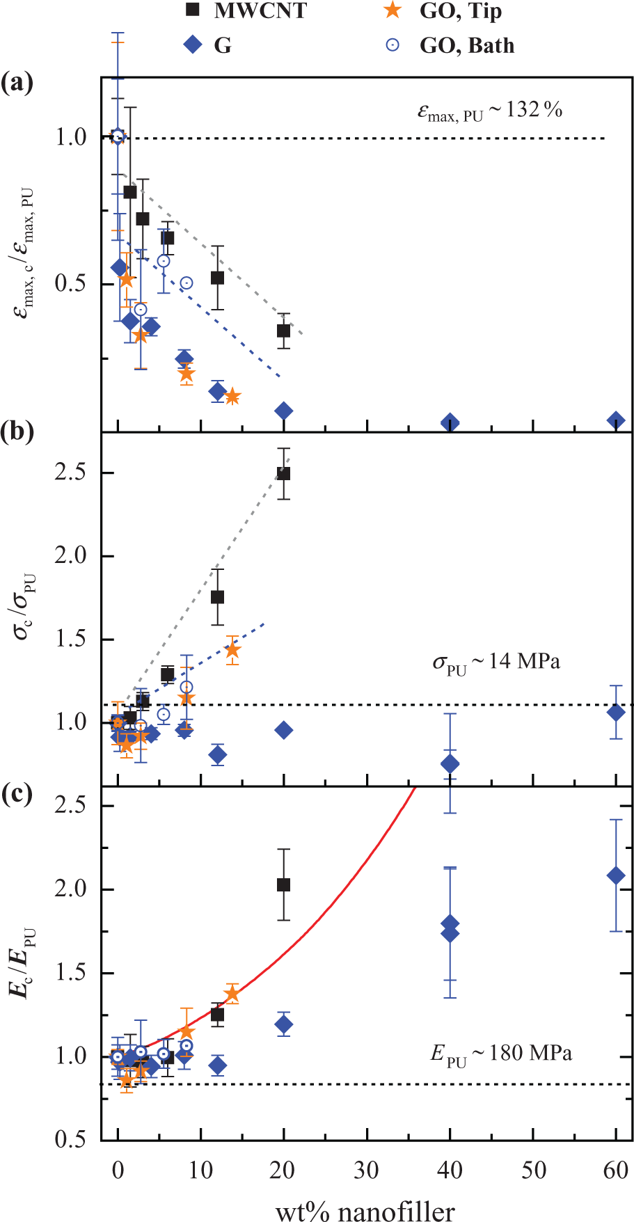
Results from tensile tests. Normalised values of (a) strain to failure, (b) strength and (c) elastic modulus of composites incorporating (▪) MWCNT, (⋄) G and (⋄) GO prepared by the solvent exchange method and (
It is also observed that composites prepared by the solvent exchange method were stronger, stiffer and slightly more ductile than composites of G. This fact could be related to a finer dispersion of GO particles and sheets and a better interaction with PU matrix due to their larger interfacial area as well as the introduced oxygenated functional groups.
The so-called Guth–Gold hydrodynamic model
25
was used for modulus prediction of the nanofiller-reinforced PU, and it is also included in Figure 4(c) for comparison
where E c and E PU are the composite and PU modulus, respectively, and φ is the filler volume fraction. The Guth–Gold model predicted well MWCNT and GO composites modulus of concentrations up to 12–14 wt%, but underestimated MWCNT reinforcing ability at higher concentrations. The model overestimated modulus of all exfoliated graphite composites.
In Figure 5, scanning electron micrograph images of composites with G and GO are shown. In addition to the much more important film thickness reduction in GO/PU composite due to higher ductility, it is seen that composite with 12 wt% G presented a slightly higher concentration of G flakes at the bottom of the film (right of Figure 5(a)) than at the surface (left). This can be explained by an incompletely satisfactory interaction between G flakes and polymer solution leading to partial decantation of large G flakes. In contrast, GO (Figure 5(b)) presented no such filler gradient, which can be matched to a better interaction between GO flakes and solvent and polymer molecules leading to a particle solvation and stabilisation. Difference in flakes size between G and GO (being the later significantly smaller) is also considered to be a reason for a favoured decantation of G larger and therefore heavier flakes.
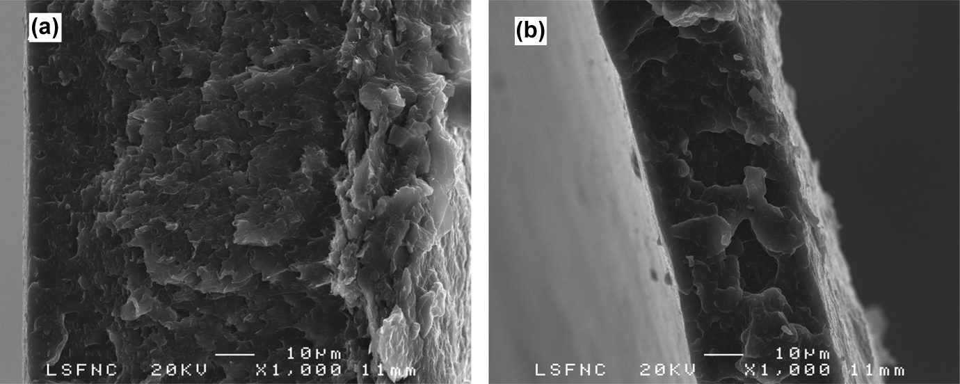
Scanning electron microscopy images of fracture surfaces of composites with (a) 12 wt% G and (b) 8 wt% GO. G: graphene; GO: graphene oxide.
Other studies performed with elastomeric PU and G composites 8 have shown the trend to increase elastic modulus with an increase in G loading, while strength remained almost imperturbable or tend to decrease at high loadings. This phenomena as well as the reduction in ductility should be matched with a reduction in plastic flow and crack propagation–dissipation capabilities. In addition, as other authors have also found, incorporation of G into PU barely increases strength at certain loading 8,9 but actually tends to decrease it at high filler fractions. 8,10 This fact should be related either to a poor interfacial shear strength between the PU matrices employed or to an uncompleted G exfoliation providing nanographite interlaminar weak shear strength, which weakens the composites mechanical performance.
Strength is improved by addition of GO by the solvent exchange method, which implies that a better stress transfer between GO and PU is achieved in this case than with G sheets. This fact could be due to a better interaction between GO for an increased interfacial area but also for a better chemical compatibility between oxygen-containing functional groups in GO and PU through dipolar interactions or hydrogen bonding. 26 In this regard, the sole publication in which the composites strength was increased by employing exfoliated G, the authors prepared composites through in situ polymerisation, 27 which could lead to anchoring of polymers onto GO and therefore to an improved stress transfer between the matrix and the filler.
The higher reduction in ductility observed when G or GO are employed as fillers, when compared to MWCNT, could be due to the larger sizes of the nanofillers and their bidimensional nature, which can effectively hinder the plastic flow of the PU SSs. The explanation of the mechanical properties of composites in terms of filler–polymer interactions is summarised in Figure 6. In Figure 6(a), it is shown that the non-hydrophilic big G flakes do not interact strongly with PU HSs at the same time they cause molecular impediment to plastic flow. In Figure 6(b), GO smaller flakes are represented interacting better with the PU HSs than in the case of G flakes but still may hinder plastic flow due to yet restricted molecular motion. In contrast, in Figure 6(c), it is shown that while MWCNT interact profoundly with PU HSs 5 they still permit certain molecular motion enabling material deformation.
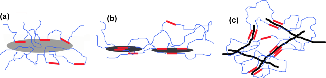
Schematic representation of different nanofillers–polymer interactions. (a) G/PU, (b) GO/PU and (c) MWCNT/PU. MWCNT: multiwalled carbon nanotubes; G: graphene; GO: graphene oxide; PU: polyurethane.
Conclusions
MWCNT, G and GO have been added to a crystalline PU with 40 wt% HS content. Solvent exchange method was necessary to effectively disperse GO platelets within PU matrix. Composites prepared with MWCNT outperformed those with either G or GO as the reinforcing element in retaining higher elongations at break and in stiffening and strengthening the material. Dimensionality of the nanofillers seems to have an important role in the strain–stress behaviour of elastomeric/filler composites, seeming that the smaller the nanofiller the stronger, stiffer and more ductile the composite becomes. Therefore, it is suggested that the methods in which smaller G or GO flakes are obtained should be pursued so that these could be confined as reinforcing agents to PUs hard domains.
Footnotes
Acknowledgements
The authors acknowledge the General Research Services of the University of the Basque Country (SGIker), and especially Microscopía Electrónica y Microanálisis de Materiales and Macroconducta-Mesoestructura-Nanotecnología units for their technical support.
Author’s Note
This work is dedicated to the memory of Dr Iñaki B. Mondragon (1954–2012) who passed away after his contribution to this work and who founded the Grupo “Materiales+Tecnologías” in 1988. He was an inspiration for all of us.
Funding
This work was financially supported by University of the Basque Country, (UPV/EHU) post-doc grant “Ayuda a la Especialización de Doctores”, Basque Government through SAIOTEK 11-S-PE11UN132 programs and in the frame of Grupos Consolidados (IT-365-07).