
Abstract
There have been various efforts on frequency selective surface in recent years, and of course, some research progress has been made, especially in numerical calculation and simulation field. However, it seems that less work is done on the processing and forming methods. Soft fabrics are periodic and have advantages over the rigid materials in lightweight, softness, low bending rigidity, which make it possible and meaningful to study their filtering property as the medium in electromagnetic field. In this paper, a kind of electromagnetic functional textile based on frequency selective surface was proposed specifically for 10 GHz, dominant frequency of X-band radar. The full-wave simulation software, HFSS v14, was used for theoretical simulation and optimization, and two complementary cross-shaped unit cells with optimum size were obtained. Then, the frequency selective fabrics were manufactured through silk-screen-printing technology and measured using transmission method. It showed that the measured and simulated results had good consistency, and the fabricated frequency selective fabrics had ideal band-stop or band-pass performance. Finally, according to the analysis of S21 curve and transmission line equivalent circuit modal, the filtering mechanism was explained and the great potential in practical application of frequency selective fabrics was further illustrated.
Keywords
Introduction
Frequency selective surface (FSS) is a periodic spatial filtering structure which has been widely used for many applications such as radome, antennas, dichroic and sub-reflector based on their band-pass or band-stop properties [1]. In recent years, the research work is mainly focused on the design and characterization of new structures, such as complex pattern, multi-layer as well as three-dimensional structure [1–4], and some research progress of FSS has been made in numerical calculation and simulation field. The fundamental algorithm, like finite element method (FEM), method of moment (MoM), finite-difference time-domain method (FDTD), and the corresponding software, like HFSS, CST, XFDTD, have been used to solve Maxwell's equations in such periodic structures [5–7]. However, it seems that less work are done about the processing and forming methods. People used to adopt electroplating, chemical plating, vacuum deposition or metallic coating to obtain conducting layer in dielectric substrate first and then select photo-etching, digital carved milling or laser machining and cutting to form the expected periodic pattern [8]. The printed circuit board (PCB) technology is also popular for the designers who are familiar with it [9]. Thus, the final products based on FSS are mainly rigid plates and composites, rarely involving soft materials, which are also widely used in our daily life.
Researchers also make efforts to study the electromagnetic (EM) properties of textiles and develop EM-functional fabrics [10,11]. We all know the conductive property, dielectric property, antistatic property and many related products have appeared in the market, like EM shielding fabric, anti-ultraviolet fibre, far-infrared health textile etc. However, regardless of the actual effect of these products, researchers neglect that fabric can be a medium in EM field to cut off or make through-the-EM wave. Fabric, as a kind of typical flexible materials, has advantages over the rigid materials in lightweight, softness, low bending rigidity, which make it popular and irreplaceable in certain fields. Fabric itself is highly cyclical due to the periodic interlacement of warp yarn and weft yarn and can be easily manufactured through partial metallization process to get conductive pattern on the surface, like coating printing, silk-screen printing and computer embroidery. Thus, it is meaningful as well as feasible to study the filtering property of fabric with periodic conductive units.
EM wave brings us much convenience in military and civil fields, but it can also do much harm to the human body, electronics as well as the environment [12,13]. Specially, X-band radar with the centre frequency of 10 GHz has the function of detection and locating objects, widely used in weather forecast, environmental monitoring, geological survey, stealth technology in military combat and many other fields [14–16]. Actually, it is difficult to find detailed materials and reports of the use of textiles in these aspects due to confidentiality requirement. However, with regard to the development of antenna, radar radome and various filtering devices, the soft materials show promising prospects. For instance, the tent used to hold command post is required to shield the enemy's detection signal, while making through our communication signal, and at this point, the soft FSFs seem to be the best choice.
S-matrix and SE
In discussing general filtering problems, S-matrix is a very important indicator. To illustrate the meaning of S parameter, microwave network which focuses primarily on external characteristic of microwave elements is given in this paper. Figure 1 gives the schematic of two-port network, in which ai and bi (i = 1, 2) stand for normalized voltage incident wave and reflection wave, respectively, and they are determined by waves on the transmission line [17].
Schematic of two-port network.
Through formula deduction, S-matrix can be written as the linear relation between reflection wave b and incident wave a, and it can be derived from the following formula (1)
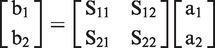
Here, S-matrix is called scattering matrix of the two ports, and each of the four S parameters has definite physical significance. Specially, S21 is transmission coefficient of port#1 when port#2 connects matched load and it can be calculated from formula (2)

The meaning of S21 is illustrated from the perspective of microwave transmission line theory, but in many cases, the energy loss due to the difference between EM impedance and the intrinsic impedance of shielding material is more intuitive for designers to characterize and evaluate the material. According to Schelkunoff Principle, for conductive monolithic materials without holes, the shielding effectiveness can be calculated from formula (3) [18]


As a medium in EM field, periodic structure, like FSS, can be also evaluated through S21 parameter. In this paper, two kinds of frequency selective fabrics (FSFs) with complementary cross-shaped units were proposed, which were supposed to shield or make through EM wave with the frequency of 10 GHz—dominant frequency of X-band radar, while shielding or making through EM wave in other frequencies. Based on S21, the simulation was accomplished and FSFs were fabricated. Through comparison of the measured and simulated results, the validity of designed FSFs was verified. Then, the filtering mechanism and great potential in practical application of FSFs were further illustrated.
Simulation and optimization
In this paper, two kinds of cross-shaped FSS were selected to design FSFs. Figure 2(a) and (b) shows the unit cell structure size of patch FSS and aperture FSS separately, in which Dx and Dy represent lateral and longitudinal size of the unit cell, m and n stand for the length and width of the cross-shape and each leaf of the cross is identical. In Figure 2, the grey area is covered with conductive metal, while the left blank area signifies the dielectric substrate. According to the empirical formula proposed by Munk [20], resonance effect will appear when the ultimate range between the two ends is approximately equal to half of the wavelength λ. In order to achieve the resonance characteristic in 10 GHz, Dx and Dy were both settled as 20 mm, and m and n were roughly selected as 10 mm and 5 mm separately.
Unit cell structure size of cross-shaped FSS (a) patch FSS; (b) aperture FSS.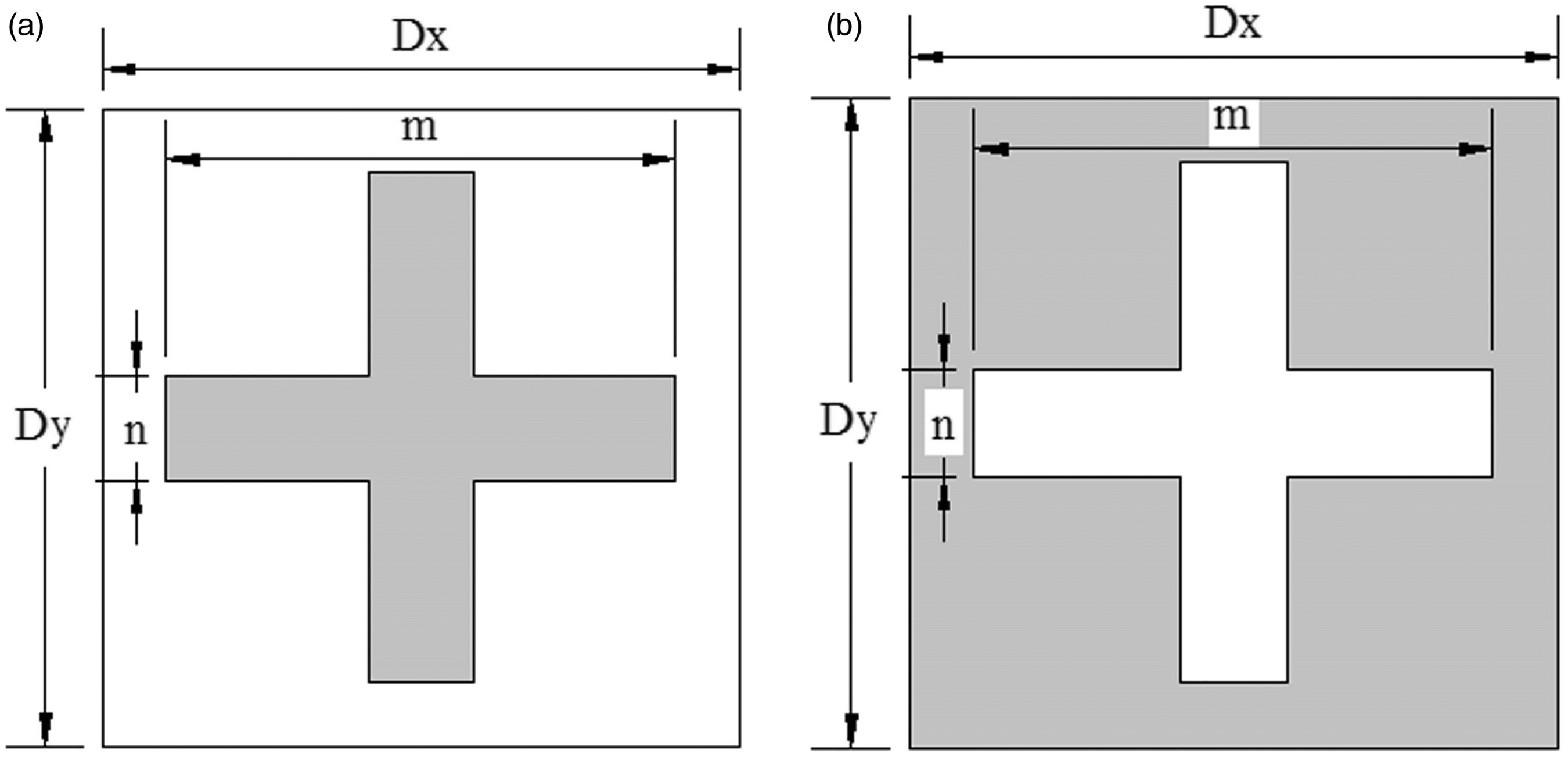
Using Floquet’s theorem for periodic surfaces such as resistive FSS, a unit cell geometry model of cross-shaped patch FSS-based FSF was simulated for its performance in HFSS software. The unit cell geometry model of FSF in HFSS is shown in Figure 3. For the convenience of modelling, the fabric was assumed to be a smooth plate with the equivalent thickness of 0.48 mm. Actually, EM properties of the fabric sample in the following experiment are similar to vacuum within the test frequency and the substrate was specified as vacuum during simulation, and the cross-shaped patch was assumed to be perfect conductor, with the thickness of 0.05 mm. The three-dimensional schematic of patch FSF is shown in Figure 4, which comprises cross-shaped patch FSS on plain woven fabric substrate. To save space, there is no list of aperture FSF in Figures 3 and 4, and it is easy to imagine according to the complementarity.
Unit cell geometry model of patch FSF in HFSS. 3D schematic of proposed patch FSF.

Simulation was performed according to the assumed structure and the desired transmission curve showed that the resonance frequency was approximately 13.8 GHz, a little declinational from the expected 10 GHz. In order to make it more precise, optimization was carried out in HFSS software to obtain the optimum dimension. Here, all the parameter values kept fixed except m and n. After calculation, the final value of m and n were set as 16 mm and 3.3 mm.
Figure 5 gives the optimized normal incidence simulated performance, in which the two curves show certain complementarity within the given frequency range, with the same resonance frequency 10 GHz. For the transmission curve of patch FSF, the peak reaches −41.23 dB (nearly all the incident waves could be shielded here), and the narrow bandwidth of −10 dB, namely the frequency range of S21 < −10 dB (more than 90% of EM waves could be blocked), is predicted from 9.16 GHz to 11.03 GHz, for both TE and TM modes. While for the transmission curve of aperture FSF, the peak comes to almost 0 dB (the corresponding EM wave can pass through the FSF totally), and the bandwidth of −0.5 dB, that is the frequency range of S21 > −0.5 dB (approximately more than 90% of EM waves could traverse the FSF) is even narrower, predicted from 9.5 GHz to 10.01 GHz.
Optimized simulated performance of FSFs.
Although the two curves present an opposite tendency, showing up different filtering property, it should also be noticed that they are not completely symmetrical. This is due to the fact that the electrical conductivity of metal material is not ideal and the conductive layer has certain thickness, which is against the premise of Babinet principle [21]. And the more important point is that the existence of dielectric substrate makes FSFs become mixed periodic structure, which causes two S parameters to change in different degrees when they interact with EM wave and makes the curves not exactly the same as expected. Therefore, to obtain precisely complementary filtering curves, two kinds of FSFs should be designed, respectively, according to specific simulation and calculation methods.
Experiment
Sample manufacture
Through simulation, the values of structural parameters were obtained to design the real samples. As mentioned above, the plain polyester fabric was selected in the paper as the substrate of FSFs. For the warp as well as weft yarn, the count is 40 S and the density of arrangement is 286 × 224 in 10 cm. The weight of the fabric is 178 g/m2 and the equivalent thickness is 0.48 mm. The permittivity test was accomplished using parallel plate method in Beijing University of Technology, and the value almost kept 1.0 when the frequency of the electric field was set in GHz.
To form periodic conductive units on the surface of designed FSFs, the silk-screen-printing technology was used. Here, the conductive silver pulp (Hanstars HS-8200Ag) with less than 12 mΩ/▪ sheet resistance was chosen as the printing material onto the fabric surface. The two screen plates with the corresponding periodic cross-shaped pattern were made through photographic method, and the mesh number of polyester silk screen was 200 per square centimetre. By means of manual operation with doctor blade, the conductive slurry was periodically transferred onto the surface of the fabric and then the samples were dried under 80℃ for 30 min in the oven. After the test, the coating thickness was determined to be roughly 0.05 mm using the thickness gauge.
The photographs of two kinds of fabricated FSFs are shown in Figure 6(a) and (b). The sample size was cut into 180 mm × 180 mm for the following normative testing, and therefore, there were totally nine lines by nine rows cross-shaped unit cells on the surface of each sample.
Photographs of fabricated FSFs (a) patch FSF; (b) aperture FSF.
Testing procedure
The testing was performed in EM Compatibility Laboratory of Beijing University of Technology using Transmission Method. The lateral view of testing system is shown in Figure 7, and we can see that the whole testing system consists of three parts: E8257D Signal Generator and Transmitting Antenna, Absorbing Wall, Receiving Antenna and E7405A Spectrum Analyser. Figure 8 gives the photograph of real testing environment, including transmitting antenna and absorbing wall, which is removable and made of pyramidal construction units, with the total size of 2.5 m × 2 m. It should be noticed that in the middle of the absorbing wall (red square portion in Figure 8), the sample with the square size of 180 mm × 180 mm could be placed to test the transmission performance. The calibration must be completed prior to the formal experiment to confirm the centre lines of the two antennas and the testing board are overlapped.
The lateral view of testing system. The photograph of real testing environment.

To eliminate the influence of testing environment and the coaxial line, three-step testing is needed to obtain the final precise result. First, the test is performed with nothing in the testing board. Then, the FSF sample is placed in the red square area to get the corresponding result. And finally, a total reflection plate is selected and placed in the same portion to determine the transmission performance. The transmission coefficient of the sample is calculated from the following formula (5)

Actually, in the testing process, the unit of power is dBm, and the transformational relation between P(mW) and

By means of formula (6), the formula (4) can be translated into the following formula (7)

In the formula (7), the meaning of
Analysis and discussion
Discussion of results
After the sample preparation and testing procedure, the actual outcome was obtained. Figure 9(a) and (b) shows the comparison of measured and simulated results for the two kinds of complementary structure, from which we can see that the measured results coincide with simulated results in both of the FSFs.
(a) Comparison of measured and simulated results for patch FSF. (b) Comparison of measured and simulated results for aperture FSF.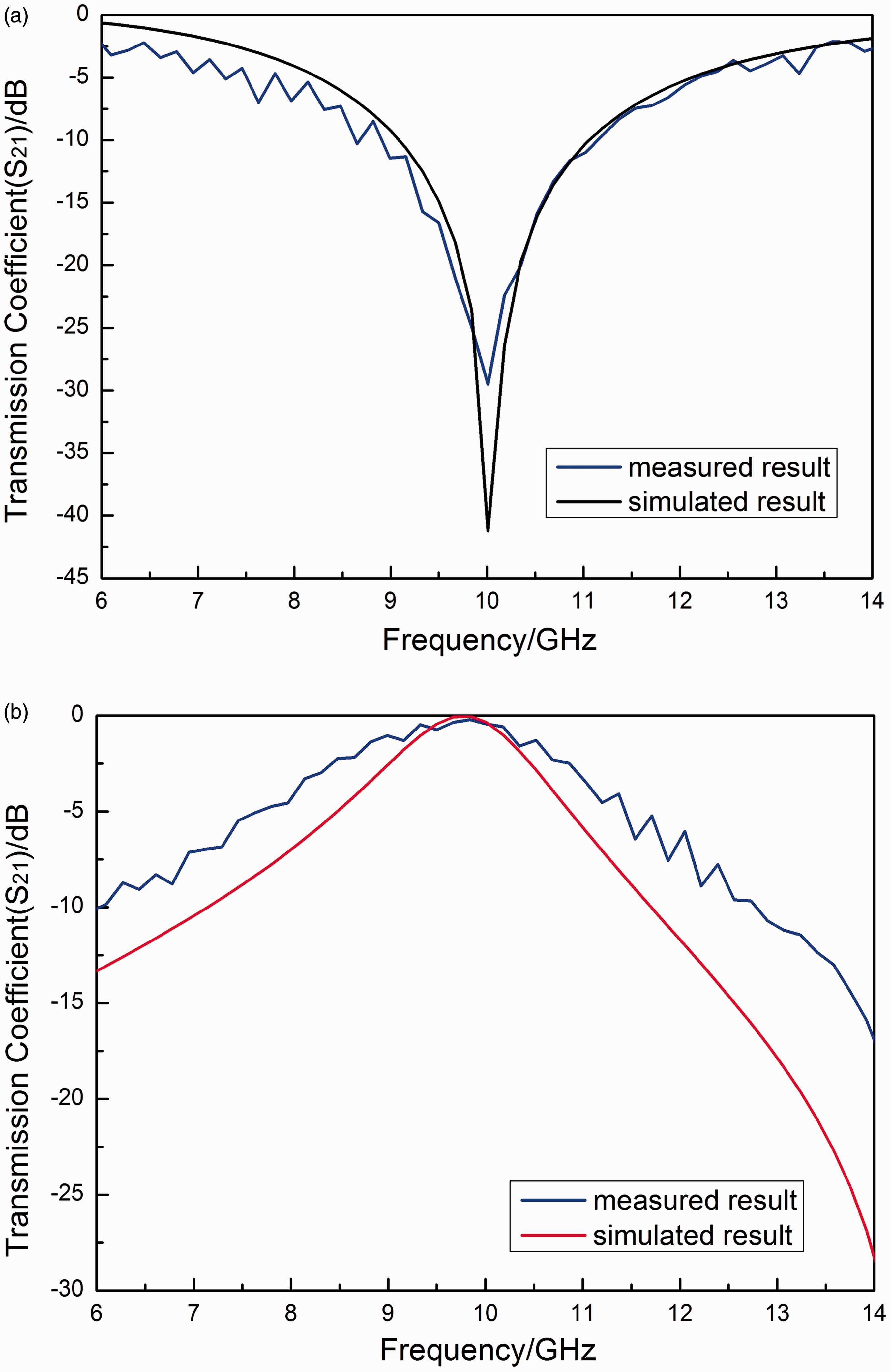
From the measured curve in Figure 9(a), we can easily find that the resonance effect appears in 10 GHz as expected, peaking roughly −29.49 dB, and the bandwidth of −10 dB is approximately 2.0 GHz, from 8.99 GHz to 11.03 GHz. The measured curve in Figure 9(b) also shows the obvious resonance peak in the position of 10 GHz, with the transmission coefficient value up to almost 0 dB, and the bandwidth of −0.5 dB is approximately 0.7 GHz, from 9.33 GHz to 10.05 GHz. Both the samples show obvious frequency selective characteristic, and the two bandwidths are very narrow.
Though the measured curves and corresponding simulated curves show the same trend, they are not exactly the same on the whole, especially in Figure 9(b). We can see that the gap in specific frequency band is over 10 dB, such as the two resonance peaks in Figure 9(a). It can be attributed to the processing precision, the finiteness of the sample size, the imperfection of the conductive metal, the unfairness of fabric surface due to yarn buckling and many other factors, which are not considered in simulation.
The filtering mechanism of FSFs is identical with FSS and the dielectric fabric substrate can be used to support the conductive metal units. Here, the interaction between FSFs and EM wave is described qualitatively and the analytical method applies to patch FSF as well as aperture FSF. For incidence of EM wave to the FSF, the component of electric field parallel to the metal units drives the electrons to oscillate and then the induced current is formed in metal surface. Therefore, part of the energy of the incident EM wave is converted into kinetic energy all the moving electrons need, and other energy can pass through the FSF to continue to transmit. In a particular frequency, all the energy is used to keep electron motion, and the additional scattering field excited by the moving electrons can offset the EM field on the back area of FSF, which makes the transmission coefficient become zero and produce the resonance effect. The secondary field can also transmit towards the front area of FSF, which makes the FSF show reflection characteristic. The similar physical mechanism can be easily understood that the FSF is nearly transparent to incident EM wave in other frequencies and shows transmission characteristic [22].
Through the discussion, we know that the measured results are ideal and the product can be used to selectively shield or make through the X-band radar. Comparison of the results verifies the validity of the simulation as well as the experiment methods, which can be also used to design FSFs with different sizes of units or other periodic patterns.
Further analysis by EC modal
Though the filtering mechanism of FSF is illustrated above, the quantitative characterization is still needed to obtain the intuitive understanding. Here, the transmission line equivalent circuit method is used to further analyse the transmission characteristic aiming at the specific patch FSF, and the principle also applies to aperture FSF. Figure 10(a) gives the schematic plan of patch FSF, in which relevant geometric parameters are marked and Figure 10(b) shows the corresponding transmission line equivalent circuit, which consists of a series RC circuit modelling the conductive patch FSS layer shunted across the short-circuited transmission line of length d modelling the dielectric fabric [23,24].
(a) Schematic plan of patch FSF. (b) Transmission line equivalent circuit.
Without regard to the role of dielectric substrate, the surface impedance of FSS layer can be derived from formula (8)

It can be inferred that the impedance of FSS has one zero at a certain frequency. When the impedance comes to zero, the current goes straight into the ground and the wave is unable to transmit through the surface. Thereby, the resonance frequency (f0) of FSS is derived from formula (9)

However, when it comes to FSF, the resonance frequency will shift due to the single-loaded role. Considering the relative permittivity (ɛr) of the dielectric fabric, the approximate frequency value can be calculated from formula (10) [25]

To obtain the transmission coefficient of the FSF for normal incidence, the free-space input impedance of FSF must be calculated by formula (11). And then, the transmission coefficient of the FSF is derived for the given EC as formula (12) [26]


From the above analysis, we know that the EC modal can provide physical insight into the performance of the FSF, and learn how geometric and physical parameters affect filtering performance. From the EC modal, the relative fitness functions could be defined more appropriately for optimization purposes [23]. The dielectric fabric is not just to support the conductive metal units but also adjust the position and resonance peak of the transmission curve, and therefore, soft textiles with different dielectric properties should be selected specially to modify filtering curves to better meet the requirements.
The potential applications of FSFs
In this paper, two kinds of specific FSFs were fabricated and the filtering performance was discussed. However, EM wave technique is ubiquitous and the boundaries of pros and cons are not clear in different situations. Considering the fact that many different filtering properties are needed in military as well as civilian field, various products should be developed according to the final applications.
Fabric has its own periodic structure for the textile processing technology and the fibre denier is in the same order as the wavelength of EM wave. And as mentioned above, the partially metallization technology is mature to form conductive pattern in textiles. Therefore, the FSFs with wanted performance are easily manufactured by mutual combination of various processes. Though few, there are actually some publications involving filtering textiles [27–29].
In our daily life, the FSFs can be widely used due to the properties of softness, lightweight, low bending rigidity. Based on the existing research ideas and methods, the advanced protective clothing with good wearability can be developed aiming at the main frequency of harmful EM wave. Many household textiles, like veiling and window hangings, are also expected to possess the filtering performance to some extent and the proposed FSFs may be used here. The design of industrial textiles, like construction textiles, packaging bags, various fabric reinforced composites, might find a new direction through structural design instead of material selection.
In military and research fields, the FSFs can be new candidates if the mechanical property, thermal property and other properties can meet the requirement. For instance, the textile antenna has already been designed based on patch arrays [30,31]. And FSFs may serve as the filling materials of radar absorbing agent to reduce radar cross section (RCS) and achieve stealth performance in a particular waveband [32]. The soft FSFs can cut off particular signal and energy transmission, which can be used to develop weapons in electronic warfare. Metamaterial is a kind of artificial three-dimensional periodic material with a lot of novel properties, such as superlensing, negative refraction, cloaking [33] and the multi-layer fabrics as well as 3D fabrics, including spacer fabrics, velvet and plush fabrics, can be easily processed into corresponding structure, which may be a new method to study the internal mechanism of external response [34].
Through the discussion, we learn that there will be a variety of applications of FSFs in the future, and much more efforts are needed in the design and fabrication of FSFs. It is a meaningful and worthwhile work and should attract the attention of relevant researchers.
Conclusion
In this paper, the concept of novel FSFs was proposed and the research ideas were illustrated based on two kinds of cross-shaped FSFs. After simulation using HFSS v14, sample manufacture using silk-screen printing technology and testing procedure using Transmission Method, the final S21 curves were obtained. It can be seen that the two FSFs show obvious frequency selective characteristics in the given frequency range, with ideal resonance peaks in 10 GHz and narrow bandwidths, which could fully meet general requirements. To explain the filtering mechanism, qualitative analysis as well as quantitative calculation using EC modal were carried out based on the specific FSFs fabricated in this paper. Finally, the potential applications of FSFs were discussed and various filtering products may be developed according to different requirements.
Though the existing work offers a perspective to design and develop novel frequency selective products, there are still some deficiencies to be improved. In simulation, the fabric substrate is equivalent to a smooth plate in geometry models to simplify calculation, ignoring the scattering effect due to the surface roughness, which causes the error and needs to make more accurate analysis. Actually, dielectric properties of the fabric in EM field vary with the frequency, and in this paper, the relative permittivity and dielectric loss are roughly fixed as constants, which needs more work to explore the effect. In practical application, incident direction of EM wave is not necessarily perpendicular to FSFs surface and the S21 curves with different incident angles should be obtained to give a more comprehensive evaluation. In later study, we will continue the research topic regarding the unsolved problems and devote more efforts in the area.
Footnotes
Declaration of Conflicting Interests
The author(s) declared no potential conflicts of interest with respect to the research, authorship, and/or publication of this article.
Funding
The author(s) received no financial support for the research, authorship, and/or publication of this article.