
Abstract
Composites have now revolutionized most industries, like aerospace, marine, electrical, transportation, and have proved to be a worthy alternative to other traditional materials. However for a further comprehensive usage, the tailorability of hybrid composites according to the specific application needs on a large-scale production basis is required. In this regard, one of the major fundamental research fields here involves a technology development based on the multiaxial warp-knitting technique for the production of bionic-inspired and application-specific textile preforms that are force compliant and exhibit multi-material design. This article presents a newly developed yarn (warp) path manipulation unit for multiaxial warp-knitting machines that enables a targeted production of customized textile preforms with the above characteristics. The technological development cycle and their experimental validation to demonstrate the feasibility of new technology through production of some patterns for different field of applications are then discussed.
Introduction
Constantly increasing prices for raw materials and energy, as well as current discourse on the reduction of CO2 emissions, place an emphasis on the advantages of lightweight construction and its resource-conserving production methods [1–3]. For future applications in the automobile industry, energy and mechanical engineering, a production system for lightweight constructions with a multi-material design is being currently pursued in an attempt to obtain greater material and energy efficiency [4]. The advantage of continuous fiber-reinforced polymer (FRP) composites lies in their flexible and adaptable material structure, allowing the material characteristics to be customized and the characteristic anisotropy to be optimally fitted according to the required production methods [5–9]. The development of competitive high-performance products and highly automated processes is currently witnessing an integral change, showing a move away from conventional materials and technologies and a migration to tailored multicomponent materials and bionic-inspired design-oriented production processes. For the design and construction of composites as effective load-bearing structures, the two most important criteria to be considered are the optimization of force flow, in accordance to the principle “Form follows Force” and minimization of the material usage in terms of sustainability. This forms the fundamental basis for the lightweight character of the structure. References for effective load-bearing structures can be found abundant in nature.
The potential for bionic-inspired design for lightweight constructions has already been identified [10,11]. The design principle in nature has heterogeneous, anisotropic, and multifunctional characteristics [12]. Various bionic-inspired composite-based structures have demonstrated that this principle can be efficiently used in new innovative structural systems through tailoring material properties in a certain direction [13–15]. Also, future structural form must be material adapted to achieve high efficiency in a large-scale industrial application. This is of high relevance particularly to the textile reinforcements. Polymer-reinforced glass or carbon fiber structures are orthotropic material where the strength and stiffness are dependent on the fiber orientations. Many of the supporting structures in nature exhibit such orthotropic material properties. Woods in the trees are characterized by these special orthotropic properties, especially, in the radial direction to the wood rays that run along the stem. Studies indicate that the nature has its own way of managing loads if one considers the fiber orientation in the form of soft, spindle-shaped curves around a knothole of the wood in the tree trunk (Figure 1(a)). This load path aligned orientation of the wood rays act as a model to the composite structures in terms of their fiber arrangement in the notch region that are under tensile or compressive load relation [16]. Similarly, the wings of a dragon fly are another classical example of inspiration for the lightweight construction [17] (Figure 1(b)). The wings of the dragon fly are stabilized by a smartly arranged wire or tubular system that runs across the length of their wings. Such a design in textile-reinforced sails or wings could help in improving the functionality of the composite structures. However, the realization of these potentials in case of composite structures, especially for textile reinforcements, till date has been minimal and not been fully exploited.
Sample load optimized geometry as seen in the nature (a) knot-hole in the tree trunk and (b) wing of a dragonfly.
Multiaxial warp-knitting (stitch-bonding) technology is an extremely productive technology in terms of the quantity and quality of fabrics produced [18]. Research activity in this field of technology has been carried out to realise an optimal and precise fiber placement through yarn manipulation in accordance to the load distribution [19,20]. The initial work on warp yarn manipulation technology at the Institute of Textile Machinery and High Performance Technology, Technische Universität Dresden dates back to 1986 where controllers for warp yarns were first developed for the warp-knitting machine Malimo 14016 [21]. However, a halt in production of such type machines together with far too little yarn guide tubes, stepper motor, and a production rate similar to the creep speed of modern machines leads to the conclusion that this technology is outdated. But the concept of warp yarn manipulation in itself offers a great flexibility to adapt the textile reinforcements according to the applied loads. Unlike the normal fiber placement technology, the fibers need not be laid beforehand and can be manipulated in a larger production scale. Integration of functional and sensor yarns in-line during the production can lead to the creation of a new generation of cost-efficient innovative and adaptive composite structures.
Inspiration from bionics together with the concept of warp yarn manipulation opens up a new way of thinking where the fundamental technologies can be principally enhanced to be made suitable for a resource-efficient mass-production of lightweight structures with high-performance and functional density. Combining discrete and material-specific processes to create bionic-inspired technologies will lead to multi-material and application-specific design that makes the lightweight composite structures suited for complex demands. This paper presents and discusses a newly developed flexible and highly automated warp yarn path manipulation system, where the multiaxial warp-knitting technology is fundamentally enhanced to produce bionically inspired as well as highly complex textile preforms suited for large-scale production of fiber-reinforced composites, e.g. automotive, energy and mechanical industry.
Development of warp yarn manipulation device
The implementation of load-conforming orientation or additional reinforcements can be realized through warp yarn path manipulation. Here the additional yarns (0° warp yarns) can be brought in at places that will be subjected to increased loading. The manipulation of the yarn paths based on the multiaxial warp-knitting technology is dependent on the functionality of the machine and also based on a specialized underlying open-grid structure. This possibility of manipulating the warp yarns based on an open-grid not only opens up innumerous field of application like civil, automotive, machine, and plant constructions for the textile reinforced structures but also forms a basis for accurate manipulation. The existing stitch-bonding process on a multiaxial warp-knitting machine involves binding of the 0° warp yarns over the 90° weft yarns. A bonding process with weft yarns over warp yarns is not realizable. Given this constraint, the manipulation of warp yarns can be achieved only over a weft yarn layer. This opens up two processing methods, in which, warp yarns to be manipulated can either be sandwiched between the 0° warp yarn and 90° weft yarn layer or brought on top of the 0° warp yarn layer. The sandwiching of the warp yarns to be manipulated between the two layers is particularly advantageous as at low yarn tensions or in the case of yarn excess, a secure stitch formation and yarn fixation can be guaranteed. Moreover, this solution also offers the possibility of bringing additional warp yarn path manipulation units through which functional yarns could be integrated on top of the fabric.
The yarn tension for holding the yarns stretched and for their retrieval in case of yarn excess forms an absolute factor of significance for the manipulation unit. The tensile force required for holding the yarn in tension depends largely on the following factors namely, yarn count, production speed, bonding thread tension, structural stability, and the displacement distance. Also, the forces occurring in the underlying grid cannot be neglected during the manipulation of yarn paths as the intersections of the grid serve as a guiding parameter for the yarn displacement. Hence, it is highly important that the resulting forces across the machine width can be taken up 90° weft yarns. If these forces are alternatively brought on the 0° warp yarns, it would lead to the displacement of grid thereby affecting the functionality and accuracy of the system. These above factors are the major requisites for the design and development of the manipulation unit. Based on these, different possibilities of yarn displacement schematics were then analyzed.
Yarn offset analysis and schematics
Abstracted version of the manipulated warp yarn course over a base grid.
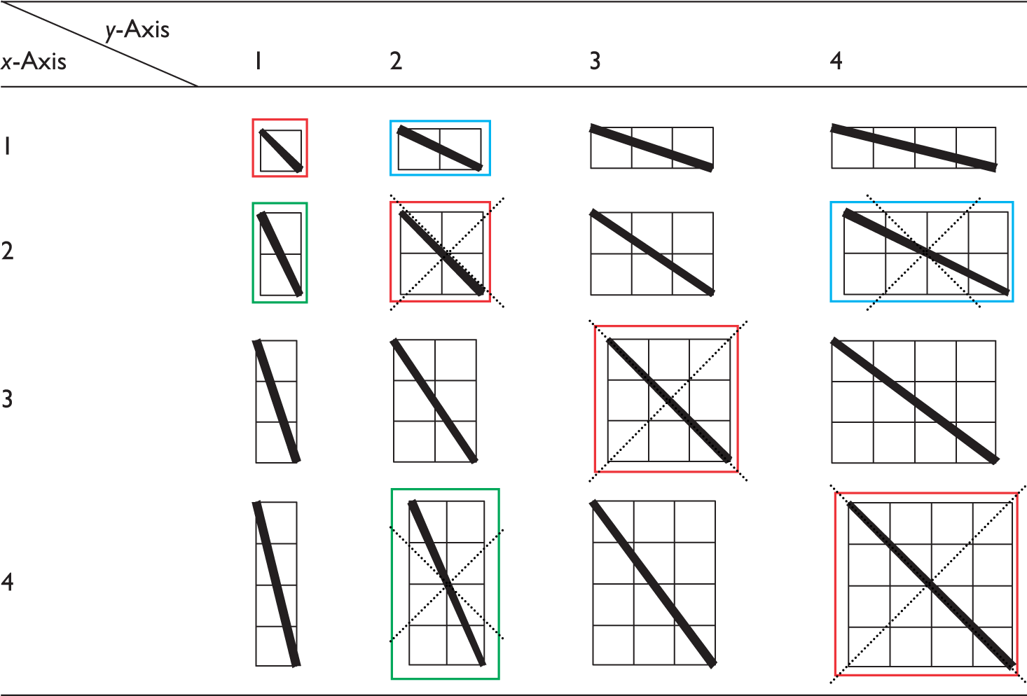
Such yarn courses might not only lead to unbound yarn areas but also prevents an effective force transmission in the textile structure. However, the rovings and the type of local reinforcements play a decisive role in deciding the suitable offset variants. An increased offset along the y-axis results in the smaller bonding areas of the yarns across the manipulated length thereby leading to structural instability. Based on the above analysis, the basic variants that are most suited in terms of the bonding stability needs to be selected.
Description of manipulated yarn course
For a better description and calculation of convenient warp yarn course using the above schematics, a reliable model representation is required. An abstract representation analog to the offset schematics depicting the manipulated yarn (thick black line) course over a grid is presented in Figure 2(a). The production direction is represented in the x-axis, while the y-axis represents the machine width (Figure 2b).
(a) graphical representation for depicting the manipulated warp yarn course and (b) orientation in a warp-knitting machine.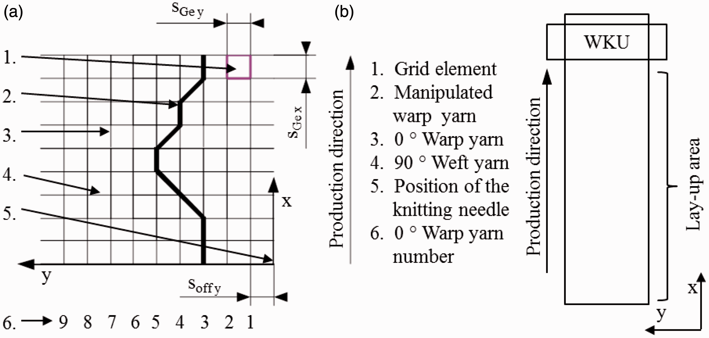
The starting point (null reference) is defined as the production start time (t = 0 s) along the x-axis and the outer right position of the knitting needle (s = 0 m). The dimensions of the grid element, whose width denoted as SGE, y and length denoted as SGE, x consist of the distance between the centers of the respective 0° warp and 90° weft yarns, forms an important control parameter. The offset of warp yarn along the grid in the axis direction is denoted by the increasing order of the warp and weft yarn displaced from the origin. The yarn displacement is calculated in grid elements (Ge) and represented as integer value, wherein the position at any given point in vector notation reflects the amount of displacement in the x- and y-direction. The data (1; 2), for example, represents an offset of two grid element in the y-direction for an offset of one grid element in the x-direction again. The y-values can assume positive and negative values depending on direction of the offset either along or against the direction of axis.
The x-values always remain positive as they represent the production direction. The path offset of the warp yarn on each grid unit must be defined. The absolute coordinates of the start and end points are not described here, but only the relative direction and path change across each grid element. The description of the displacement takes place in a chronological order. In case where the direction and the displacement offset does not change across the grid elements, they can be combined into parameters of higher order. For example, three displacements of the same order (1; 1), (1; 1) one behind the other can be combined into a higher order of (2; 2) as shown in sample pattern in Figure 3.
Sample manipulated yarn course and the offset pattern.
Design and integration of the manipulation unit
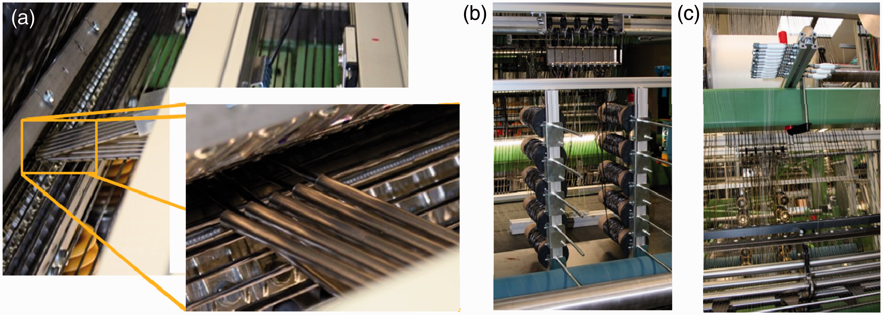
The design of yarn path manipulation unit allows the positioning of 0° yarns in the production direction at exact positions where the yarns are required to fulfill additional functions e.g. sensory networks for structural health monitoring. Figure 4 shows a conceptual integration of the manipulation unit in a multiaxial warp-knitting (stitch-bonding) machine. The manipulation unit is integrated in such a way that the yarn guide can reach directly into the knitting point that allows for an offset adjusted according to the grid element and the manipulated yarns can be accurately bonded over the grid intersection. In order to realize the crossing over of yarn course patterns during manipulation, the yarns are aligned on separate guide bars extending across the working width. The yarn is guided by tubes, which allows for gentle transportation across the entire machine width of 50 in. (ca. 127 cm) with a slight enlargement at the ends. The two yarn guide blocks are currently designed to carry a minimum of five tubes each and are extendable according to the requirements (Figure 5(a)). Each warp yarn is fed from individual spools into the tubular guide (Figure 5(b)). The yarns drawn from these spools are guided into the knitting area with the help of guide-, break- and switch devices.
Concept for integration of the manipulation unit onto a multiaxial warp knitting (stitch-bonding) machine. Realization of the warp yarn manipulation device in the multiaxial warp knitting (stitch-bonding) machine (a) yarn guide block with tubular guide, (b) individual yarn feed spools, and (c) individual yarn feed for loop threads.
A return mechanism with yarn storage caters to the compensation of the spare yarn lengths resulting from a pattern-related motion of the yarn guide. An individual thread feeding system for the bonding thread is also realized as varying stitching lengths are required for each yarn depending upon the manipulation path (Figure 5(c)). This enables the knitting needles to consume the required yarn length for the loop formation.
Functional description of the yarn path manipulation unit
The motion of the yarn guides are numerically controlled by drives and synchronized with the warp-knitting machine. The recording of the movement for the weft alignment process is carried out with the help of an external absolute encoder connected to a transport chain. The information about the path and speed of the transport chain are recorded during the guidance. A laser sensor mounted over the weft yarns is used to record their width and the distance between two subsequent yarns. The drive control and motion are then carried out on the basis of a modular system solution Simotion (Siemens AG, Germany). The offset data for the yarn guide block is derived from the yarn course calculation. With help of the process control, the offset datum is used for movement of yarn guide until the intersection point of the grid element. The processing of subsequent data for the next manipulation starts when this intersection point is reached. A high level of precision and positioning accuracy is required so that the manipulated yarns are bonded at the intersection point of the grid elements, as these elements form the basis of further yarn course. The details of the weft yarn recorded by the laser sensor are evaluated by an external encoder. In this way, the distance until the next weft yarn for knitting is available can be derived. The release of the next data set in the path manipulation program is set independently to a fixed point within the period of the last weft thread, so that any variance during the weft yarn layup is compensated. Also, subsequent release of the data set for the next located weft yarns always occur at the same fictional coordinate system in the machine. In order to ensure a secure fixation of the manipulated warp yarns, the movements of the manipulated yarns are synchronized with the knitting needle with a further sensor that detects the needle position. Figure 6 shows the geometrical representation of a manipulation cycle and the fixation of the manipulated yarn.
Geometrical assumptions for motion and secure bonding of the yarns.
Technology validation
In order to validate the developed technology, a test program was drawn for a targeted production of bionic-inspired manipulated convex and concave patterns (Figure 7). The possibility of bringing flexible additional local reinforcements as desired on the textile preform layers through yarn manipulation can be thereby demonstrated.
Targeted warp yarn manipulation patterns.
Also besides the yarn path manipulation, additional functional yarns can also be integrated into the textiles. The manipulation of the yarns over an underlying textile grid offers an immense potential not only for creating smart textiles through integration of yarns but also in fixing sensor elements on preform surface e.g. implementation of heating function, pressure sensor integration.
For the production of the sample patterns, the operational setup of the yarn manipulation unit was built in such a way that warp yarn to be manipulated is guided as close as possible into the knitting area and the yarns are manipulated in such a way that they are bonded over the grid intersection. Glass fiber as manipulation yarns were used for the test samples. The production of these samples was carried out on a specially modified multiaxial stitch-bonding machine MALIMO 14024 from Karl Mayer Malimo Textilmaschinenfabrik GmbH.
As can be seen in Figure 8(b), the manipulation yarn are fed through the needle like yarn guide. In order to achieve an overlapping manipulated course as in Figure 7b, the two yarn guide blocks are mounted on two separate linear rails that can move across the entire width of the machine (Figure 8(a)). In order to demonstrate the flexibility of the warp yarn manipulation system, a part of the working width of the machine can be used to produce the samples as seen in Figure 9(a). On the basis of the defined patterns, the samples were produced and the concept of warp yarn path manipulation was validated (Figure 9(b)).
Yarn manipulation unit overlapping yarn guide and yarn guided into the warp-knitting area. Production sample in the machine and produced sample pattern.

Sample application areas
In general, it is highly desired that the stresses occurring in the textile preforms are in line with the end structure. This results in the requirement for a greatest possible freedom in the arrangement and orientation of the individual textile layers. This new technological development of warp yarn path manipulation has opened up new and innovative application areas of producing cost-effective textile reinforced structures in accordance to the component-specific restrictions as imposed by the user. With this, it is now possible to create hybrid composite structures in accordance to the flow of forces. The sample areas of application are elucidated in the following sections.
Bionic-inspired and textile multigrid reinforcements
The polyurethane long fiber injection offers a proven processing technology for the production of large-scale lightweight structures with high-quality surface and good mechanical characteristics like the interior door panels of cars. However, this method is currently limited to the production of components without oriented continuous fiber reinforcement. With the achievement of load path aligned reinforcement using the warp yarn manipulation pattern similar to the bionic-inspired knot-hole arrangement can now be realized (Figure 10(a)). This leads to a significant improvement in the impact properties of such components. Also, the design of textile assumes a great significance when realizing complex free-form surface constructions that might require additional local reinforcements (Figure 10(b)). With application of path (warp) manipulation unit additional reinforcement yarns can be brought according to the direction of load that caters to the increased load especially at the edges or at the load inserting zones.
(a) bionic inspire textile reinforcement and (b) textile reinforcements for surface constructions.
Textile reinforcements with gradient properties
In general, a global online structural health monitoring in FRP requires a built-in textile-based sensor systems. This has a significant advantage over integrating the sensors as an additional separate element since it leads to deficiencies in the structure. With the adoption of warp yarn path manipulation unit, sensor patterns can now be realized directly together with additional local reinforcement on the load bearing textile preforms during their production (Figure 11(a) and (b)). This offers a reliable, quick, and efficient alternative to the existing conventional technology [22].
(a) rotor blade sketch of a small wind power plant with textile-based sensors [22] and (b) pretest of textile sensor integrated biaxial grid fabric.
Textile reinforcement as multiaxial thermoplastic tapes
A new manufacturing process based on an innovative wrapping concept aims at large-scale one-shot manufacturing of complex rotationally symmetric and asymmetric near-net-shape structures has been developed. Multiaxial multiply prepreg is wrapped here around an object core using feeding systems and process modules analogue to the taping techniques and inline consolidated. In this way, optimal and precise fiber placement can be achieved devoid of overlap and the anisotropic properties of the fiber material can be fully exploited. This new concept leads to an improved cost and production efficiency as compared to the conventional laying up of preimpregnated single ply unidirectional (UD) tapes in different orientations. The production of thick parts with precise fiber orientation and accuracy from thin UD tapes is technologically challenging. Combining different orientations of fiber layer in a single consolidated tape offers an efficient alternative solution. This would also enable the integration of various functions beforehand, thereby minimizing the processing steps and costs. The creation of multifunctional tapes require not only the integration of the functional yarns but also a force compliant yarn course in the fabric. With this developed warp yarn path manipulation unit and an additional in-line consolidation unit production of these multiaxial tapes is now practically possible using the multiaxial warp knitting technology. Figure 12 illustrates the suited machine concept for the tape production.
Machine concept for multiaxial tape production.
Summary and outlook
Within this research activity, a new modular warp yarn path manipulation unit was designed, constructed, and integrated into a multiaxial warp-knitting machine. Based on the binding mechanism in the multiaxial warp-knitting (stitch-bonding) machine, it was determined that the feed-in of the yarns for manipulation between the 90° weft and 0° warp yarns layers is the preferred solution for a secure fixation. A change in direction for the manipulated warp in the production direction is only possible after the fixation of the active yarn at the grid intersection. The manipulated warp yarn follows approximately a straight course between two intersection points. The change in direction between two points of intersection is referred to as offset. Based on the general pattern requirements offset variants (producible offsets) were then defined. This allows a universal pattern description, regardless of the actual grid size. The derivation of a calculation model with respect to the yarn position in the textile preform and the required offset position of the yarn guide element was implemented. The validation of sample patterns and application possibilities were also demonstrated.
With this development, the multiaxial warp-knitting technology together with integrated warp yarn manipulation unit offers a viable solution for energy efficient production of textile preforms with minimal material requirements. This also offers a greater flexibility to adapt the textile reinforcements to the applied loads and to integrate functional yarns in-line thereby allowing the creation of a new generation of cost-efficient innovative and adaptive composite structures. Further, this newly developed technology forms the basis of further systematic evaluation, quantitative and qualitative analysis, cost-benefit analysis of the textile reinforcements in composites. This material-specific process development will lead to multi-material application-based design that makes the lightweight composite structures suited for complex demands and large-scale manufacturing.
Footnotes
Acknowledgement
The authors are grateful to their Colleague Mr. Martin Waldmann for his valuable guidance and support.
Declaration of Conflicting Interests
The author(s) declared no potential conflicts of interest with respect to the research, authorship, and/or publication of this article.
Funding
The author(s) disclosed receipt of the following financial support for the research, authorship, and/or publication of this article: The authors would also like to acknowledge and thank the German Research Foundation for their funding of this project. This work was performed within the Federal Cluster of Excellence EXC 1075 “MERGE Technologies for Multifunctional Lightweight Structures” and supported by the German Research Foundation (DFG). Financial support is gratefully acknowledged.