
Abstract
Carbon fibres are fabricated in bundles. A single roving contains a minimum of 1000 filaments. Certain applications demand thinner bundles or even single fibres. Single fibres can be used as tool electrodes in electrochemical machining processes. Thinner rovings are needed in sensor applications to raise the electrical resistance of the carbon fibre bundle used as strain sensor. Rovings with a lower filament count cannot be delivered by carbon fibre producers. A splitting technology is therefore needed. A continuous bundle splitting technique was developed. It uses mechanical means, liquid flow and variations in winding force and speed to separate the filaments. The impact of winding parameters and of the liquid flow on the splitting result was quantified in experiments with the developed splitting system. An automatic and continuous splitting of carbon fibre rovings was realised. Smaller bundles of carbon fibre filaments can be provided. There is a solution to satisfy the demand on finer carbon fibre rovings.
Introduction
Motivation
The smallest commercially available carbon fibre (CF) rovings contain 1000 filaments [1,2]. Different applications demand smaller CF bundles. Rovings with a filament count of 500 could be used as sewing thread in the production of carbon fibre reinforced plastics [3]. Thicker bundles are not useful for sewing. CF shows piezoresistive properties. They can be integrated as strain sensors into glass fibre reinforced plastics in the form of bundles [4]. The electrical resistance of the available thick bundles is too low for some applications. Thinner bundles are therefore desired to adjust the resistance. But there are no smaller bundles available at the moment. Single CF filaments are applied as cutting tools in the electrochemical machining [5]. To fulfil all needs of a wire electrode, a continuous and at least 50 m long CF filament is necessary. There is no such filament offered on the market. All the mentioned applications demand smaller CF rovings. Due to cost restrictions, the CF production cannot be modified to produce smaller bundles. A process to split or separate CF rovings is therefore necessary to supply such rovings.
State-of-the-art of fibre bundle separation
There are some commercial applications of CF roving splitting. Publications about the investigation of bundle splitting methods are rare. Only three patents describe techniques to separate or split rovings [3,6,7]. One report describes the splitting of heavy tows [8]. Different approaches for separation are used. Kern et al. utilise an electric field in order to desize and spread the roving. The bundle goes through a weak alkaline solution to allow current flow. The roving is connected as cathode. The negative polarity of the fibres evokes an electrostatic repulsion between them. This leads to spreading [6]. Geßler et al. use a fluid flow, streaming opposed to the fibre path, to split rovings. Water is used as fluid. The splitting can be supported by air injection or a cutting edge positioned in the splitting channel [3]. The use of combs and fulling tools to spread rovings is also mentioned there. A mechanical method to split rovings is described by Pfitzer. A mechanical spreading station stays first. Oscillating or rotating cutters divide the flattened bundle and the separate strands are wound [7]. Toho Tenax also uses a mechanical slitting process to divide heavy tows into regular rovings in order to reduce production costs for CF [8]. Different types of slitter rolls were tested as separator. A single roll showed the best results. The shape of the most promising roll is eccentric. It has flat bottom grooves and rotates counter to the tow moving direction. Only small fuzz balls are formed during slitting [8]. Since this method is used for tow separation only, a transfer of the results to the splitting of rovings seems difficult. Further details on the efficiency of all the mentioned techniques and on the splitting or separation quality are unknown. Splitting systems cannot be bought. It is therefore interesting to further investigate roving splitting.
The development of a splitting system for this investigation is based on the results of preliminary tests of the efficiency of different spreading methods. The spreading of fibre bundles is the first step towards splitting or separation. Spreading is already used in textile processes. Different effects are known to have a spreading impact on a roving. Mechanical [9,10], hydraulic [11], pneumatic [12,13], acoustic [14] and electrostatic influences [15] result in the broadening of fibre bundles (comp. Figure 1).
Principles of fibre bundle spreading: (a) mechanical spreading by means of a convex roller, (b) mechanical spreading on expandable material between two angled support discs, (c) acoustic spreading with loud speaker, (d) pneumatic using an air stream, (e) hydraulic spreading via fluid flow.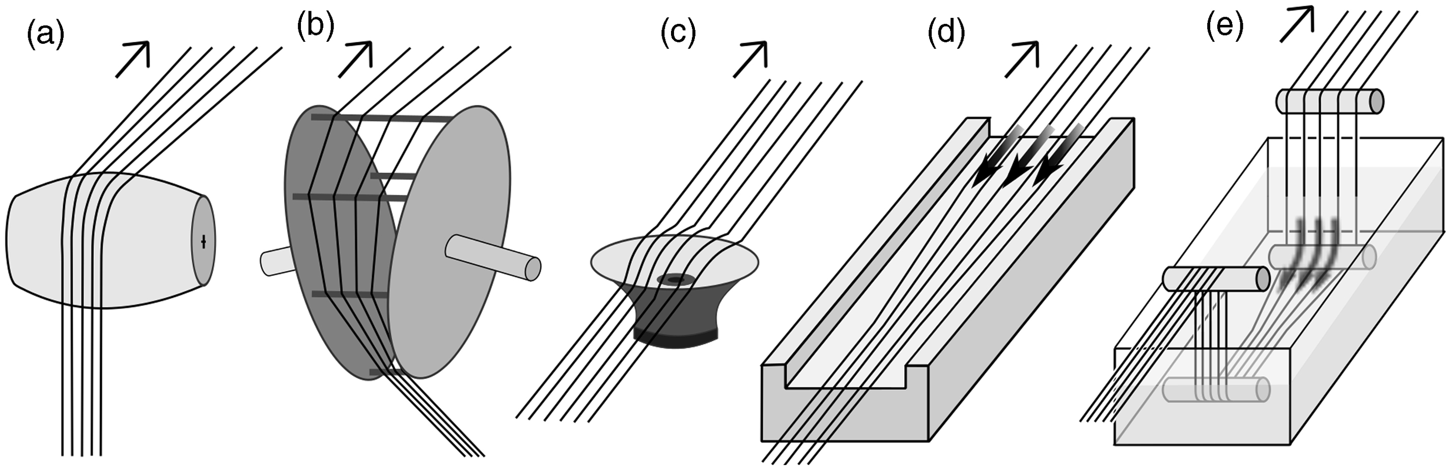
Mechanical spreading devices are very effective due to the form-locked guiding of the bundle parts. Convex rollers are a simple solution for mechanical spreading (Figure 1(a)). The highest efficiency is seen in the use of an expandable material between two angled support discs like described in the literature [10,16]. Fibre bundles enter the spreader at the point where the discs are closest together and exit at the point where the discs are furthest apart [10]. The fibre bundles are broadened with the expansion of the flexible material on this way (Figure 1(b)). The restricted guidance of the fibre bundle and the direct contact to machine parts are disadvantages of the mechanical spreading. Both result in a high amount of broken fibres. This influences the development of a splitting system. It is decided to omit mechanical solutions with a strong destructive effect. The winding systems rely on components which are in direct mechanical contact to the fibre bundle. The roving guide elements are made smooth.
The spreading effect of a liquid flow is seen as very effective. One example of this kind can be seen in Figure 1(e). The spreading force can be regulated by manipulation of the flow parameters. It can be varied over a broad range. Liquid flow spreading allows homogeneous broadening of fibre bundles [11]. The force on each filament is comparable. There are no force peeks expected. This results in a smaller amount of fibre breakage compared to the mechanical methods. Hydraulic techniques are therefore interesting for the development of a splitting system.
Different spreading approaches make use of pneumatic effects. One patent describes pneumatic spreading to form a tape with parallel filaments. The fibre tows pass through venturi spreaders in opposite direction to the primary air flow in the venturi (Figure 1(d)). This principle results in a progressive spreading [12]. Air combs are also used to spread fibre tows. Forced air, which is lead through the bundle, further spreads the filaments. An efficient spreading can be achieved in combination with rollers [13]. The spreading effect of pneumatic methods is expected to be low. A strong winding force demands a strong transverse force to spread or split the roving. In order to accomplish these forces pneumatically, high air flow velocities are necessary. A complicated set-up seems to be needed to build a pneumatic splitting system. Pneumatic approaches are therefore not used for the development of a splitting system.
Acoustic spreading methods are not used in the splitting system either. Their spreading impact seems to be low too. It is possible that acoustic effects can additionally support the broadening. The application of acoustic methods seems to be useful in combination with other spreading effects, but not as a primary means.
Preliminary investigations
A series of preliminary investigations were made. Based on the state of the art, the methods with a high spreading potential were chosen and verified in tests. The series included:
experiments on the spreading behaviour of rovings guided over rubberised rollers in acetone; guiding of fibre bundles through acetone filled u-profiles; experiments on the filament separation with cannulas; tests on the spreading impact of mechanical combs on fibre bundles lead through acetone or water; investigations on the spreading potential of vibrations stimulated by ultrasonic sound or eccentric; and experiments on spreading by means of liquid or air flow.
The spreading impact of the investigated methods was mainly poor. Some of the approaches resulted in damaging side effects. The use of rubberised rollers provided no significant spreading. No spreading effect could be found for the guiding of fibres through u-profiles with acetone inside. The direct separation of filaments by means of cannulas did not work either. Only short sections of filaments could be withdrawn by this method. The use of mechanical combs resulted in the massive generation of clews. The rovings broke subsequently. Broken filaments, which stick out of the roving, are responsible for this behaviour. Vibrations in a water or acetone bath spread the roving. Low frequencies had a stronger effect than ultrasonic sound. The stimulation of micromovement via ultrasonic sound could be observed. An air flow did not result in bundle spreading. The strongest impact was seen in the use of a hydraulic flow. This agrees with the claims of the patent mentioned before [3].
The sizing was identified to hinder efficient bundle splitting. Therefore, it was deduced that CF rovings have to be desized prior to splitting. Desizing results in reduced bundle cohesion. Desizing can be realised by chemical or thermal means. Thermal desizing is seen as most efficient. An investigation on the thermal treatment of sized CF in argon atmosphere by means of a tube oven was done to identify the optimum desizing temperature and the resulting desizing performance. High Tenacity fibres of Toho Tenax (HTA) fibres with a size content of 1.5% [2] were treated. The results can be seen in Figure 2. Efficient desizing starts at 450℃. At 500℃ the mass loss reaches 3%. Higher temperatures only slightly increase this mass loss. Minimal oxygen content in the ovens atmosphere inducing fibre oxidation could be responsible for the loss higher than the size content specified by the producer. It is also possible that the size contains water or that the size distribution is inhomogeneous, so that the overall content is higher than the producer specification. Based on the observed mass loss of more than 3% at 600℃ it was decided that the size is completely removed. Higher temperatures lead to increased fibre damage. Temperatures of more than 600℃ are therefore not sufficient for desizing. Due to a high temperature variation in the oven used for desizing with an average temperature below the core temperature and to guarantee complete size removal, 600℃ core temperature is used for desizing of fibres for splitting investigations.
Mass loss of sized CF after thermal desizing with different temperatures.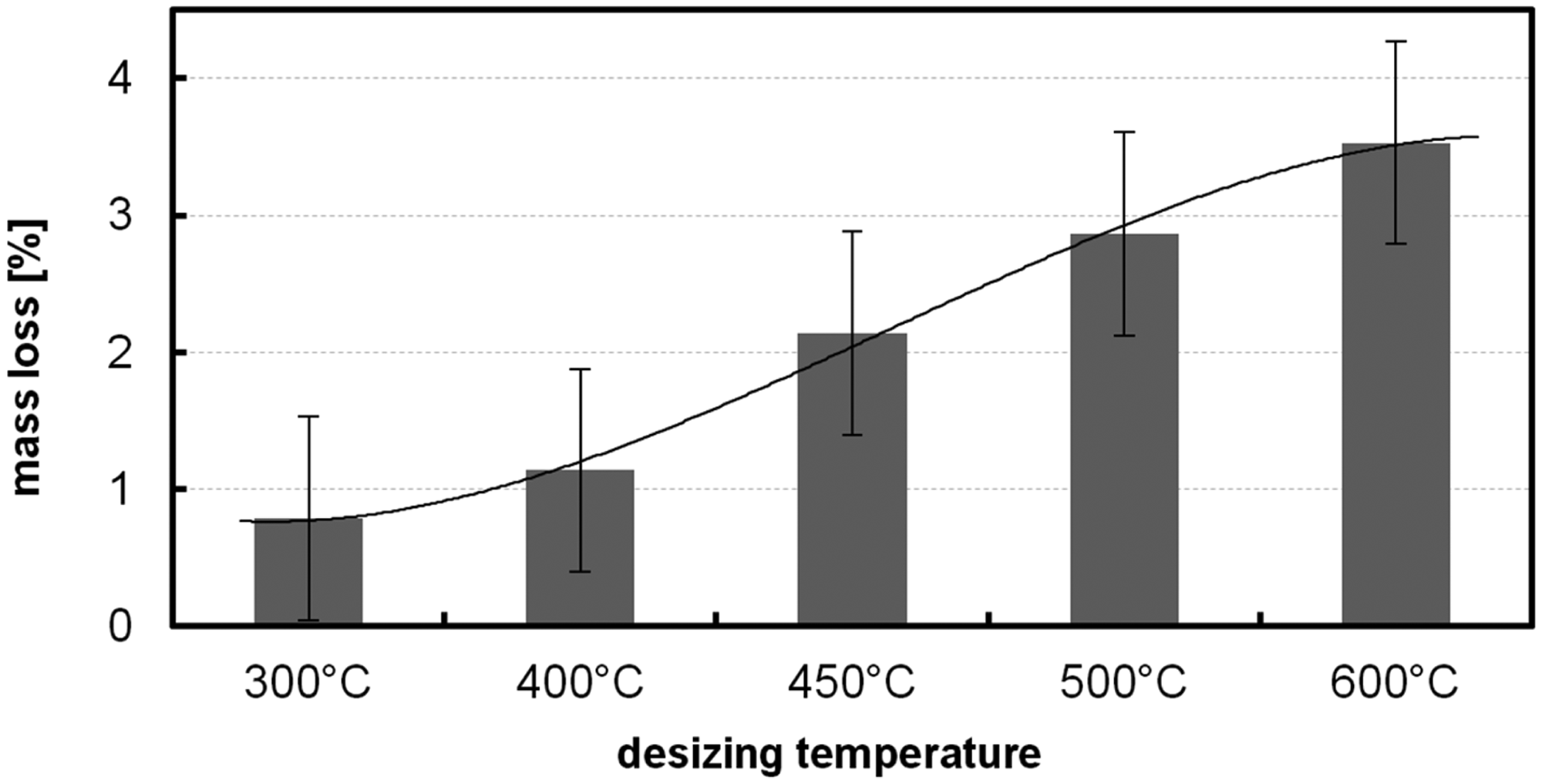
In order to reduce fibre damage, direct mechanical contact to desized bundles has to be avoided. Mechanical splitting with cutters was therefore excluded from the further development process.
Methods and materials
Splitting system set-up
The aim of the developed splitting system is to halve CF bundles. Figure 3 shows the set-up of the splitting system. The following description of the set-up reproduces the way of the CF roving through the splitting system. The numbers in brackets correspond to the numbers in Figure 3(a). Before splitting, the roving is rewound to a steel spool. A steel spool is necessary in order to thermally desize the roving prior to splitting. The rewinding is done by means of the splitting system. The cross-winding unit (11) and the magnetic wind-up unit (14) are therefore used. During the splitting process, the bundle is unwound at first (1). The roving on the steel spool is driven by an electric motor via a worm gear. The unwind speed can be varied by changing the voltage of the motor.
Fibre bundle splitting system: (a) scheme of the splitting system with 1 unwinder unit, 2 clutch, 3 CF roving, 3 a split sub-bundles, 4 PTFE plug, 5 splitting cylinder (glass), 6 counterflow die, 7 extraction tubes (glass), 8 wind-up bobbin, 9 water filter, 10 water pump, 11 cross-winding unit, 12 impulsion disk of magnetic clutch, 13 spool drive disk of magnetic clutch, 14 wind-up unit with magnetic clutch, (b) side view of the splitting system build-up.
The overall roving speed is determined by the unwinder due to the self-locking of the worm gear. Directly after unwinding, the bundle is guided through flexible Polytetrafluoroethylene (PTFE) tubes and bent glass tubes. These lead the roving into the splitting cylinder (5). The cylinder is filled with water and stands upright. The fibres enter the cylinder at the bottom, move upwards and are not guided within the cylinder. They are only strained by the moment of the wind-up unit. The run length in the cylinder is about 1.8 m. On this way the fibres can reorder and sort themselves to the given splitting side. To halve the roving, the two parts of the bundle are drawn through separate extraction tubes (7). These tubes are kept in place via a PTFE plug. A counterflow can be used to support the bundle separation. It derives from a flat die (6) sitting in between both extraction tubes (7). A transverse flow streams underneath the flat die. This flow additionally supports splitting and allows the removal of scrap fibre. A blade-type pump (10) generates the volume flow for transverse and counterflow. The drive of the pump can be varied. The relation of transverse to counterflow can be adjusted by means of valves. A sieve filter (9) with a mesh width of 1 mm is placed previous to the pump. It collects loose fibre scrap.
The split bundles (3 a) are guided to the wind-up (14) via different rollers behind the extraction tubes (7). Two separate bobbins are provided for wind-up. Cross-winding is used to guarantee an unlocked fibre lay-up. The linear movement of the cross-winding unit (11) is realised by a spindle drive connected to a linear bearing. The direction of the movement changes when the end switches are reached. Guide rollers are placed on the slide of the linear bearing. They enforce the crosswise lay-up of the split bundles. The speed of the linear movement can be varied. The wind-up unit (14) is driven by electric motors. A magnetic clutch transfers the moment to the bobbins. The clutch uses the eddy current principle. Magnets on the drive side (13) induce an electric current into the impulsion disk (12) on the motor side. This creates a magnetic flux and the moment can be transferred. The strength of the moment can be adjusted by the rotational speed of the motor. This allows to precisely control the wind-up force on each split bundle separately. It is possible to handle strong and smaller bundles. Force changes can be made dynamically within a second.
All drives are connected with a computer for control purposes. Each electrical power supply has an analogue interface. An additional digital-to-analogue interface is used to control the output of the power supplies. The control program is written in LabView. A finite state machine defines the system state in the automatic mode of the program. The unwinding speed, the wind-up force, the cross-winding speed and the pump speed can be controlled.
Materials and experimental procedure
Polyacrylnitrile-based CFs from Toho Tenax [2] were used for the splitting experiments. The first few tests were made with fibres of the type HTA5131 3 K with twist. HTA40 E13 3 K without twist was used in all other splitting processes. All fibre bundles were thermally desized prior to splitting. A tube oven with inert Ar atmosphere was used for desizing. Desizing lasted 30 min and was done in 600℃. The rovings were rewound to steel spools before, using the wind-up unit of the splitting system and the integrated cross-winding unit. After desizing the steel spool could directly be placed on the unwinder. Afterwards the rovings were manually threaded through the splitting system by means of a wire. The starting separation was done manually as well. The so split bundles were then threaded through the extraction tubes and fixed on the wind-up bobbins. Water with a small content of a liquid detergent was used as separation fluid. The detergent addition was done to reduce the surface tension of the water.
Different process modes were used in the splitting experiments. The influence of a counterflow was investigated comparing splitting results of processes with and without the use of the counterflow. Experiments with and without transverse flow were conducted. A variation of process parameters (unwinding speed, wind-up force, cross-winding speed) was done to find optimal separation conditions.
In order to be able to quantify the influence of the process parameters, the splitting length was measured. This length is defined as the distance between the inlet of the extraction tubes (7) (comp. Figure 3(a)) and the point where the separation of the two strands starts (comp. Figure 4). One measurement series compares splitting with and without counterflow. Another series of measurements was done under the variation of the wind-up force. The calibration of the force was done with a spring balance before. The minimum wind-up force is 0.34 N on each side. This value results from the friction within the wind-up system. Each splitting length represents the arithmetic average of four single measurements. The splitting length was used to calculate the inner fibre-bundle adhesion subsequently.
Regular splitting procedure and splitting length depending on the wind-up force.
Results and discussion
Splitting process and the splitting length
After threading the initial splitting length was determined. Under the minimum wind-up force (0.34 N) a splitting length of 900 mm was achieved. The wind-up force was increased to 1.29 N in order to start the splitting procedure. This increase initially raised the splitting length to 1300 mm. No further increase could be observed after the process starts.
During the ongoing splitting process shorter splitting lengths were achieved. The results of the measurement series on the influence of the wind-up force to the splitting length are shown in Figure 4. The blue marks represent splitting without counterflow (without pump). All red marks are associated to the achieved splitting lengths under the support of the counterflow (with pump). The graphs are derived from the average as a linear approximation. It can be seen that the splitting length is influenced by the wind-up force. An increase of the wind-up force leads to an increase of the splitting length. The splitting length under counterflow shows a stronger variance than without counterflow. With the help of the counterflow, longer splitting length can be achieved. The maximum splitting length was about 700 mm while splitting with counterflow, using a wind-up force of about 3 N per side.
The bundle splitting was realised continuously. Different side effects were observed. After a splitting length of 50 m a twist of the bundle could be seen in the untwisted bundle. A rotation of the bundle could be observed in the splitting cylinder. The bundle diameter and the splitting length decreased. Splitting was not possible anymore. A manual interruption was necessary to restart the splitting process. The twist was removed and the bundle rethreaded. A significant increase of the splitting length was seen after the restart of the splitting process. Another accumulation of twist, which occurred after another 50 m, spontaneously dissolved without manual intervention. This was indicated by a sudden increase of the splitting length. These observations reveal that the specific untwisted CF yarn contains twists. The twists span over a short length of a few 10 m, are made in both directions and dissolve each other. Detailed investigation of the yarn is necessary to find out if there is a twist pattern. This could be used to optimise the splitting process.
Another side effect is the formation of a fibre band, spanning between both extraction tubes and over the counterflow die (comp. Figure 5(a)). The band was generated when no counterflow was used. The fibre bundle contains fibre agglomerates. The adhesion of some of the small fibre agglomerates was so strong that they could not be split from the sub-bundle. This results in a switchover of the concerned fibre agglomerate from one to the other extraction tube during splitting. The fibre agglomerate brakes and it remains between the extraction tubes. Parts of the fibre band were taken away by the sub-bundles. But subsequently the band grew stronger. With a certain size, the extraction of the sub-bundles was hindered. The friction was then too high and one bundle broke. The splitting had to be stopped.
Side effects of the splitting process: (a) formation of a fibre band, (b) interlocking of fibre strands and spool layers observed for rewound spools.
Using the counterflow with a medium pump power and with an average wind-up force of 1.6 N per side, a continuous splitting without interruption was realised. There was only an insignificant formation of fibre band below the counterflow die. The counterflow causes the fibre material to break. The loose fibre could then be washed away and was efficiently filtered out. A continuous and uniform splitting was observed in the experiments using a maximum unwinding speed of 55 cm/min.
An interlock of fibres was observed for the rewound spools (comp. Figure 5(b)). This interlock was even stronger for the separated fibres on their spools. The interlock leads to fibre breakage during unwinding. For already split bundles the loss of fibre material is so strong that the bundle breaks. Further unwinding was then impossible. The interlock problem derives from an insufficient cross-winding. This is related to the geometry of the wind-up device and the spools. Due to an edge on both side of the wind-up spools, the roller which guides the fibre strands for cross-winding purpose had a long distance to the spooled surface. The cross-winding movement was therefore buffered and not followed directly. The geometry of the spools was optimised in order to avoid this negative effect.
The influence of a dynamic variation of the wind-up force on the splitting length was investigated too. The bundle strain was varied via breaking of the wind-up spool (8) (Figure 3(a)) or acceleration of the impulsion disk (12) (Figure 3(a)). Both methods led to a relative movement of the fibres of one sub-bundle in relation to the other sub-bundle. The splitting length increased with both types of wind-up variation. Splitting was enhanced, less fibres broke and fewer clew was formed. Only qualitative observations were done so far concerning the dynamic wind-up. Further investigations are necessary to quantify these methods.
Splitting force and inner bundle adhesion
Based on the measurement series of the splitting length in dependence of the wind-up force, the effective splitting force was calculated. The splitting force is equivalent to the inner bundle adhesion of the CF roving. Forces with different effective directions are applied to the bundle during splitting. Therefore, a balance of forces exists in the splitting area. Figure 6 shows the geometric model of the splitting area. The wind-up force Geometric model of the splitting area and formulation of the equation to calculate the splitting force Fsplit out of the wind-up force Fwind, the splitting length lsplit and the distance between the inlets of the extraction tubes lext.

The internal friction of the bundle is antagonistic to the splitting force. In order to split the bundle, the splitting force has to be stronger than the internal friction. This equilibrium of forces determines the splitting length. It means that the variation of the internal bundle friction is responsible for the variation of the splitting length. When a bundle part with higher inner friction arrives at the splitting area, the splitting length decreases. This increases the splitting angle and therefore the splitting force, splitting continuous.
The measurement series of the splitting length was recalculated. Based on equation (1) the splitting forces were determined for each average splitting length of the series. The result is shown in Figure 7(a). The variation in the splitting force is relatively small. There is no direct correlation to the splitting length. These results led to the assumption that the inner bundle adhesion or friction is relatively consistent. The average splitting force was therefore determined. The results are shown in Figure 7(b) for both kinds of splitting processes (without and with counterflow). The inner bundle adhesion was deduced out of the average value of splitting without counterflow. A HTA40 E13 3 K CF bundle has an average inner friction of 0.082 ± 0.016 N when it is split. A splitting force of this height is at least necessary to split the bundle. For splitting with counterflow a smaller force is required. The force of the liquid flow reduces the necessary mechanical force to about 0.070 ± 0.022 N. The liquid flow has an average splitting impact of about 0.012 N. It means that the impact of the counterflow is relatively small. Splitting therefore is mainly based on mechanical force.
Determination of the splitting force and the average splitting force: (a) diagram with the recalculated data of Figure 3 showing the dependency between splitting length and splitting force, (b) comparison of the average splitting forces of splitting without and with counterflow.
Splitting force and distance of the extraction tubes
For different constant wind-up forces the continuous correlation between splitting length and splitting force was calculated using equation (1). The distance of the extraction tubes of the existing splitting system was used (30 mm). The result can be seen in Figure 8. Obviously there is an exponential correlation. For all reasonable wind-up forces the splitting force strongly rises with a decreasing splitting length smaller than 400 mm. There is only a slight increase for splitting lengths greater than 600 mm. Due to the observed average inner bundle friction (0.08 N), the working point of splitting, with the tested system, is situated in a region with a medium slope of the splitting force curve. The variations of the splitting force are therefore relatively strong with changes of the inner bundle friction. This could be a reason for increased fibre damage.
Reflection of the geometric dependence between splitting length and splitting force for different wind-up forces – splitting force increases exponentially to the decrease of the splitting length, longer distance between the extraction tubes (60 mm) raises the splitting force (dotted grey curve).
A smoother splitting with less fibre stress could be reached with an enlarged distance of the extraction tubes. This results in a stronger splitting force without increase of the wind-up force. A distance of 60 mm for the inlets of the extraction tubes places the working point of splitting into the smooth region. An average splitting length longer than 800 mm can be expected then. The splitting force trajectory with the optimised distance of the extraction tubes is shown in Figure 7 (dotted grey curve). The deviation radius of the separated strands at the inlet of the extraction tubes becomes smaller with an increased distance of the tubes. This results in stronger friction and stronger fibre bending. Rollers should be installed in order to minimise the fibre stress due to a smaller deviation radius at the inlets. The increase of the splitting length additionally gives the opportunity to raise the splitting speed.
Summary and conclusion
A continuous splitting of CF rovings was realised successfully. A splitting system was developed and experiments were carried out. The splitting process is based on mechanical means. The splitting force is the horizontal component of the wind-up force drawing the strands diagonally. Splitting is supported by a counterflow. This flow removes fibre scrap and stimulates inner fibre movement. An additional transverse flow is used to support the scrap fibre removal. It is possible to split untwisted CF rovings continuously. Rovings with a smaller fibre count can be served. Based on the experimental data the inner CF bundle adhesion was calculated. The determined average bundle adhesion of the fibre type HTA40 E13 3 K is 0.082 ± 0.016 N.
In order to improve the splitting process an increase of the distance of the extraction tubes to 60 mm is necessary. Thus, the splitting force can be raised without increase of the wind-up force. Then it is possible to raise the splitting speed. In the same breath an integration of guide rollers at the inlets of the extraction tubes should be made. This is required to lower the friction and to increase the bundle bending angle in order to reduce the fibre stress.
Footnotes
Acknowledgements
The authors thank Eckhard Rülke, Todor Sultani, Stefan Demmig and Clemens Ulbricht for their support in the development of the fibre bundle splitting system. Their contribution to find appropriate splitting techniques, to build up the system and to realise the splitting experiments is highly acknowledged. The experimental work was realised at the Institute of Materials Science and Engineering of the Chemnitz University of Technology.
Declaration of Conflicting Interests
The author(s) declared no potential conflicts of interest with respect to the research, authorship, and/or publication of this article.
Funding
The author(s) disclosed receipt of the following financial support for the research, authorship, and/or publication of this article: This work was supported by the German Research Foundation and the European Social Fund.