
Abstract
The mechanical performance of additively manufactured composites is strongly governed by fibre–matrix interfacial adhesion, which can be compromised by process-induced imperfections. This study examines how fibre embedded length controls interfacial adhesion behaviour and failure mechanisms in 3D-printed continuous carbon fibre-reinforced polyethylene terephthalate glycol (PETG) composites, using single-fibre pull-out testing combined with scanning electron microscopy (SEM). Specimens with embedded lengths ranging from 1 mm to 50 mm were tested to capture the transition between fibre slippage and fibre fracture. A critical embedded length (L c ) of 4.88 ± 0.54 mm was determined, beyond which fibre fracture dominates. The apparent interfacial shear strength (IFSS) was measured as 18.6 ± 1.2 MPa, while the interfacial fracture energy (G c ) was calculated as 27.3 J/m2. A linear traction–separation cohesive law was fitted based on these experimental parameters. SEM imaging reveals distinct microstructural features associated with the two failure modes. These findings establish practical benchmarks for optimising fibre placement, orientation strategies, and load transfer efficiency in 3D-printed composites. The outcomes contribute to the advancement of lightweight composite structures for aerospace and automotive applications.
Keywords
Introduction
Composite materials, particularly carbon fibre-reinforced polymer (CFRP), have gained widespread adoption across industries such as aerospace, automotive, and renewable energy due to their superior strength-to-weight ratio and tailorable mechanical properties.1–4 These attributes make CFRPs an ideal candidate for lightweight, 5 high-performance applications. 6 The growing interest in sustainable manufacturing practices and the increasing demand for customisable, complex geometries have further propelled the use of additive manufacturing (AM) techniques for composite fabrication.7–10 Among these, material extrusion, commonly known as fused filament fabrication (FFF), 11 has emerged as a cost-effective and versatile method for manufacturing continuous fibre-reinforced thermoplastic composites (CFRTPCs).12–16
Despite its advantages, the adoption of material extrusion for CFRP fabrication is hindered by challenges in interfacial adhesion between the carbon fibres and the thermoplastic matrix. 17 Weak interfacial bonding compromises the mechanical properties, particularly the interlaminar shear strength, of 3D-printed composites when compared to those manufactured via conventional methods such as vacuum bagging or injection moulding. 18 The root cause of this limitation often lies in inadequate fibre wetting and suboptimal bonding mechanisms during the extrusion process. Addressing these interfacial challenges is critical to unlocking the full potential of 3D-printed CFRPs. 19
The interfacial adhesion between carbon fibres and thermoplastic matrices is critically dependent on the wetting behaviour during the fabrication process.20–22 Wetting, in this context, refers to the ability of the molten thermoplastic matrix to spread and adhere to the surface of the reinforcing fibres. 23 Effective wetting ensures intimate contact at the fibre-matrix interface, facilitating strong physical and chemical bonding mechanisms that are essential for efficient load transfer and overall composite performance.24,25 The degree of wetting is influenced by several factors, including the surface energy of the materials, the viscosity of the molten matrix, the contact angle between the fibre and the polymer, and the fibre-embedded length within the matrix. 26 As a consequence, insufficient wetting can lead to the formation of voids and weak interfaces, which degrade the mechanical properties of the composite, particularly its tensile strength and interlaminar shear strength. This issue is further exacerbated in additive manufacturing processes like material extrusion, where parameters such as nozzle design, extrusion temperature, and layer deposition can significantly affect the quality of wetting. 27
Recent studies have begun to explore the interfacial behaviour of carbon fibre-thermoplastic systems. 28 Advanced microscopy techniques, such as scanning electron microscopy (SEM), have provided insights into fibre-matrix interactions, while mechanical testing has quantified the influence of factors such as embedded length, matrix composition, and printing parameters. A study by Maqsood et al. 29 highlights that achieving proper impregnation of continuous carbon fibres with the thermoplastic matrix is crucial for enhancing mechanical properties. The research emphasises that insufficient wetting during the material extrusion process can lead to void formation and weak interfacial bonding, adversely affecting the composite performance. Similarly, Pandelidi et al. 30 discuss the challenges associated with the extrusion additive manufacturing of continuous fibre-reinforced polymers. The review identifies that inadequate fibre wetting and bonding mechanisms during extrusion can result in poor adhesion between the fibre and matrix, leading to compromised mechanical properties. Yang et al. 31 used Scanning Electron Microscopy (SEM) to analyse the fibre-matrix interfaces in carbon fibre-reinforced ABS composites. The images reveal critical insights: (a) low wettability of the fibre tow leads to poor impregnation and weak adhesion, (b) fibres separate from the matrix, indicating insufficient interfacial bonding, and (c) smooth fibre-matrix interfaces result in inadequate interlaminar shear strength. Valvez et al. 32 investigated the effect of annealing on Fused Filament Fabrication (FFF) printed PETG, PETG reinforced with short carbon fibres (CF), and PETG reinforced with Kevlar fibres. The study revealed significant improvements in the post-printing mechanical properties, particularly for CF/PETG composites. Under optimal annealing conditions, the bending strength and modulus of CF/PETG increased by approximately 31.8% and 61.1%, respectively, compared to the as-printed state (the corresponding gains for neat PETG were 10.2% and 17.6%). These improvements were attributed to improved interlayer bonding and increased polymer chain mobility, mechanisms directly relevant to interfacial adhesion in carbon/PETG systems.
However, a significant gap remains in understanding how embedded length and wetting mechanisms govern the fibre–matrix interface in additively manufactured continuous fibre composites. While critical embedded length and interfacial shear strength have been extensively studied in conventionally processed composites, their direct application to composite fibre co-extrusion additively manufactured (CFC-AM) systems is not straightforward. The combined effects of thermoplastic matrices, pre-impregnated carbon fibre tows, and printing-induced defects such as incomplete impregnation and void formation create interfacial behaviours that differ fundamentally from those observed in traditional processing routes. Addressing this gap is essential for optimising interfacial adhesion and ensuring the scalability of CFC-AM for structural applications.
To address this gap, we introduce an interfacial characterisation framework for continuous fibre co-extrusion additive manufacturing, enabling the first experimental determination of the embedded-length-dependent transition in failure mode and the direct extraction of cohesive interfacial parameters that are currently unavailable for printed continuous-fibre systems.
In this study, we investigate the interfacial adhesion of continuous carbon fibres embedded in a PETG matrix produced via fibre co-extrusion additive manufacturing. The influence of embedded length on interfacial performance is systematically examined using single-fibre pull-out testing, complemented by SEM analysis of the resulting fracture surfaces. By correlating embedded length, interfacial load response, and microstructural features, we provide new insight into the load-transfer mechanisms governing material-extrusion additively manufactured composites. This integrated experimental–microstructural approach establishes a foundation for more accurate modelling of interfacial behaviour and supports the design of more reliable continuous fibre-reinforced 3D-printed composites.
Experimental details
Materials
The composite specimens in this study were manufactured by embedding continuous carbon fibre (CCF) within a polyethylene terephthalate glycol (PETG) matrix using a co-extrusion-based additive manufacturing process. The proprietary Anisoprint CCF filament (Anisoprint Sarl, Luxembourg) consists of approximately 1500 carbon monofilaments bundled into a tow with a nominal diameter of 0.35 mm. Throughout this work, the term “fibre” refers to this multi-filament tow rather than an individual carbon filament.
The tow is pre-impregnated with a photopolymer–epoxy resin system, forming a thermoset matrix around the carbon filaments and resulting in a nominal fibre volume fraction of approximately 60%. The carbon fibres have a tensile strength of 2200 MPa and an elastic modulus of 149 ± 5 GPa. This tow format was selected because it is the standard (and only) configuration compatible with the Anisoprint continuous-fibre deposition system, and has been widely reported and experimentally validated in prior studies, ensuring both technological representativeness and reproducibility.33–35
The PETG matrix material was sourced from add:north (Add North 3D, Sweden) and selected for its chemical resistance, mechanical durability, and proven compatibility with additive manufacturing. Previous studies36–38 have demonstrated that 3D-printed PETG can form strong fibre–matrix interfaces, making it an attractive choice for load-bearing composite structures.
Additive manufacturing and sample preparation
Conventional methods for evaluating interfacial shear strength (IFSS), such as the microdroplet bond test (ISO 19375:2024 standard), fibre push-out, 39 and fragmentation tests, 40 fail to provide reliable measurements for additively manufactured (AM) composites. The inherent challenges of AM, such as fibre misalignment and interfacial heterogeneity arising from layer-by-layer deposition, render these techniques ineffective. In particular, the widely used microdroplet test, which relies on precise droplet placement, is fundamentally incompatible with the anisotropic and heterogeneous interfaces of 3D-printed composites.
To overcome these limitations and accurately assess the IFSS between PETG and carbon fibre in 3D-printed composites, we adapted the single fibre pull-out test by modifying the ASTM C1557-20 standard. Originally designed to measure fibre tensile strength, this standard was extended to evaluate fibre-matrix adhesion by analysing failure modes, specifically fibre slippage relative to the embedded fibre length (see Figure 1(a)). For specimens exhibiting fibre slippage, IFSS was quantified based on the relationship between peak load, fibre diameter, and embedded length. In cases where fibre fracture occurred, the test isolated the fibre’s intrinsic tensile strength, effectively decoupling adhesion effects from fibre integrity. Specimen design for single-fibre pull-out testing: (a) Schematic of specimen geometry with key dimensions (in mm) and (b) photograph of a representative 3D-printed PETG specimen with embedded continuous carbon fibre.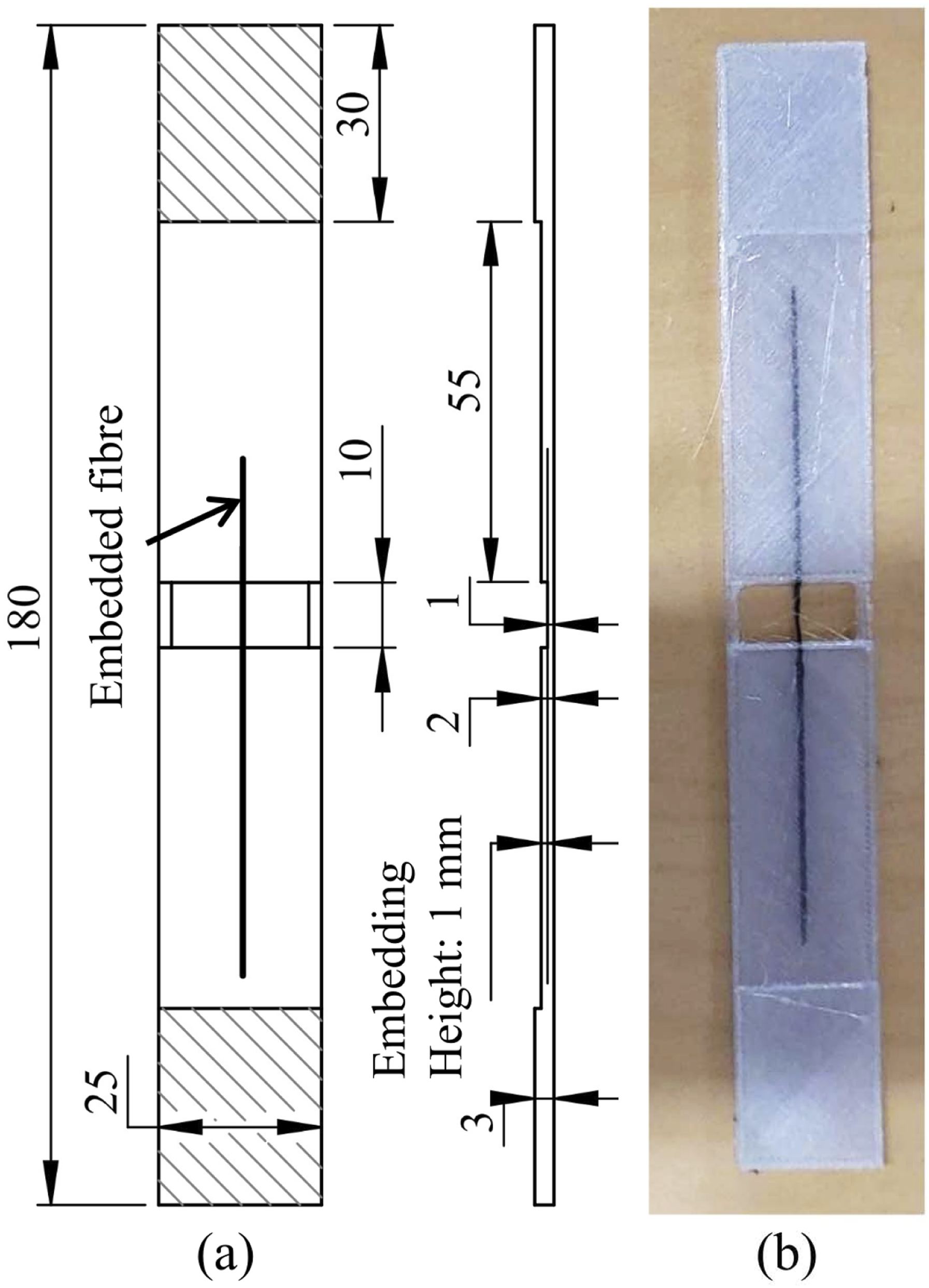
This adaptation provides a more robust and AM-tailored approach to characterising interfacial properties, bridging a critical gap in evaluating fibre-matrix interactions in 3D-printed composites. 41
The specimens were standardised to dimensions of 180 × 25 × 3 mm and incorporated a fixed embedded fibre length of 50 mm on one side. These dimensions were chosen to satisfy the gripping and loading requirements of the modified ASTM C1557 pull-out configuration while providing a sufficiently long, unsupported gauge section to minimise constraint-induced failure. The fixed embedded length, selected based on preliminary trials, ensured fracture-dominated failure at the anchored end rather than fibre slippage. The opposite side contained variable embedded lengths, enabling systematic investigation of the relationship between embedded length and interfacial adhesion (Figure 2(a)). By keeping the tow type, fibre placement, and specimen geometry constant on one side, the embedded length on the other side of the mid-plane remained the only controlled variable governing the interfacial response. Experimental setup for single-fibre pull-out testing: (a) specimen geometry and gripping configuration with variable embedded length; (b) fibre slippage failure mode; (c) fibre fracture failure mode; (d) experimental test setup.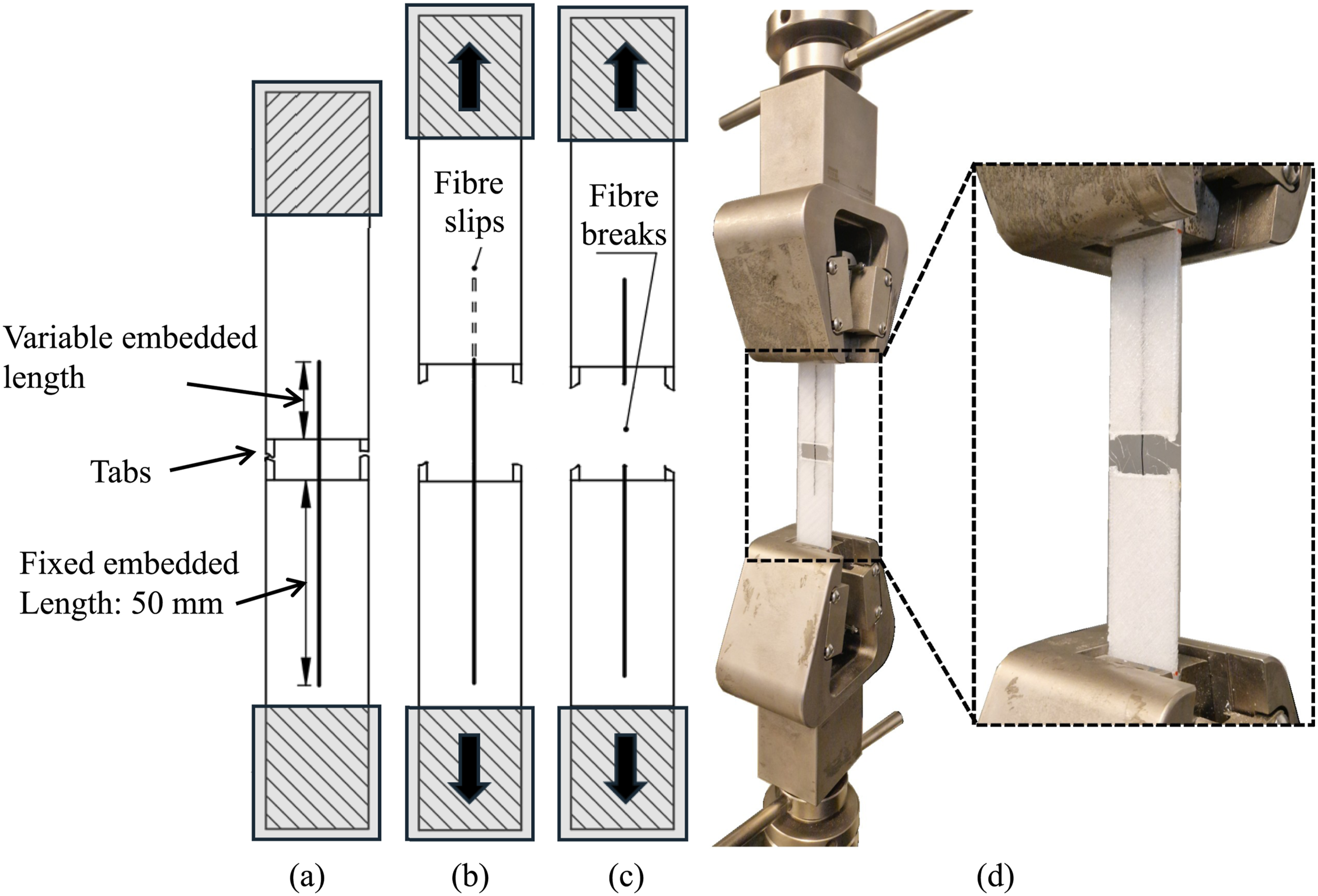
Specimen geometry was designed using CAD software and exported as. STL files, and processed in Aura slicing software (version 1.27.2) to generate the G-code for 3D printing. However, due to the lack of adequate control for fibre placement in Aura for making the single fibre specimens, manual scripting of the G-code for carbon fibre deposition was performed. The custom G-code replicated the default scripts generated by Aura in terms of movement and extrusion settings.
To achieve optimal mechanical performance, a 100% infill density was used for the PETG matrix, with key printing parameters carefully controlled. The nozzle temperature was set to 240°C to ensure proper melting and flow of the polymer, while the print bed was maintained at 80°C to minimise warping and improve interlayer adhesion. The first layer was deposited with a thickness of 0.30 mm, followed by subsequent layers printed at 0.17 mm. A total of 11 layers were printed in the gauge section, with an additional five layers added at each end to form the gripping regions. The continuous carbon fibre was embedded after the fifth layer, at an approximate height of 0.98 mm, and aligned with the longitudinal axis of the specimen. The surrounding PETG was deposited using alternating raster orientations of +45° and −45° relative to the fibre axis. The print speed was fixed at 50 mm s−1 to ensure stable material deposition while maintaining manufacturing efficiency.
The composite specimens were manufactured using an Anisoprint Composer A4 3D printer. This system incorporates an automatic fibre wetting process, which impregnates the thermoplastic matrix into the carbon fibre during deposition, enhancing fibre–matrix interfacial adhesion and overall composite integrity. Fibre and polymer deposition were carried out using the manufacturer-calibrated dual-material thermal profile, and no additional nozzle temperature tuning was performed.
Wetting between the thermoset-impregnated carbon fibre tow and the PETG matrix occur within the heated melting chamber of the printer. As the tow passes through the composite nozzle, the surrounding thermoset resin softens above its glass transition temperature (Tg), allowing it to conform and physically integrate with the PETG melt.
34
After co-extrusion, the nozzle presses and irons the fibre onto the previously printed PETG layers, facilitating impregnation of the fibre bundle (see Figure 3). However, complete impregnation may not always be achieved, as it depends on specific printing parameters and is susceptible to process-induced defects. Schematic of the continuous fibre co-extrusion 3D printer used in this work.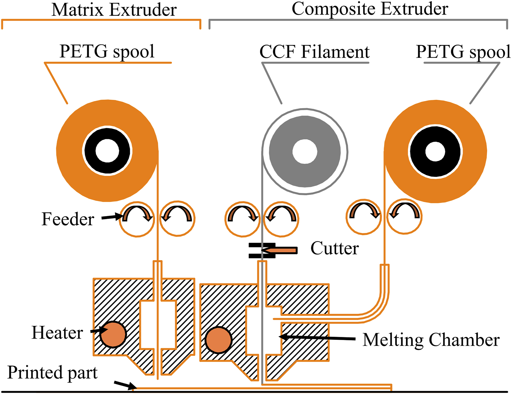
Although the thermoset resin comprises roughly 40% of the pre-impregnated tow, the PETG matrix is the dominant phase in the printed composite overall; therefore, throughout this paper, we refer to the interfacial measurements as PETG–CF adhesion.
Testing
Tensile and interfacial adhesion tests were conducted using an MTS Insight 30 kN Universal Testing Machine. The 3D-printed specimens were mounted in pneumatic grips, and specimen tabs were removed before testing (Figure 2(a)). A constant cross-head speed of 0.5 mm/min was applied to ensure uniform loading, with load and displacement data recorded incrementally until fibre failure or slippage occurred.
Initially, the embedded fibre length of 50 mm was tested, then systematically reduced in a geometric progression (24, 12, 6, and 3 mm) to determine the critical length at which fibre slippage first appeared. Post-printing measurements of the embedded length were taken with a precision of ±0.5 mm. These values are referred to as the fibre-embedded lengths (L) throughout this study. Additional specimens with L ranging from 1 to 6 mm (in 1 mm increments) were prepared and tested to provide more reliability and consistency to the results. Specimens with L below 1 mm could not be printed, as shorter fibres tended to slip out under minimal loading.
For each target embedded length L, three specimens were printed. This sample size represents a compromise between achieving sufficient data density for reliable regression and the practical constraints of fabricating and testing a wide range of embedded lengths in continuous fibre co-extruded specimens. However, post-print measurements revealed deviations between the nominal and realised values of L, resulting in a continuous distribution of embedded lengths rather than discrete nominal levels.
Post-test analysis included scanning electron microscopy (SEM) using a Zeiss Sigma VP microscope. Cross-sections of wetted specimens were gold-coated to enhance conductivity and imaged to identify interfacial defects such as voids, matrix impregnation, or fibre pullout.
Results and discussion
Critical embedded length
The tensile pull-out tests conducted on carbon fibres embedded within PETG matrix specimens revealed distinct trends in failure mechanisms and interfacial adhesion strength, both strongly influenced by the embedded length. Two principal failure modes were observed: fibre fracture and fibre slippage. A clear transition between these mechanisms was identified at an embedded length of approximately 5 mm, based on visual inspection of the fractured samples.
Figure 4 presents the load–displacement curve for a representative specimen selected from a group of three tested at each embedded length, where fibre fracture was consistently observed. For specimens with longer embedded lengths (50, 24, 12, and 6 mm), the interfacial adhesion strength exceeded the intrinsic tensile strength of the carbon fibres, leading predominantly to fibre fracture. The peak loads in these cases consistently surpassed 100 N, indicating robust interfacial bonding and efficient load transfer across the fibre–matrix interface. Representative load–displacement curves illustrating carbon fibre fracture for various embedded lengths.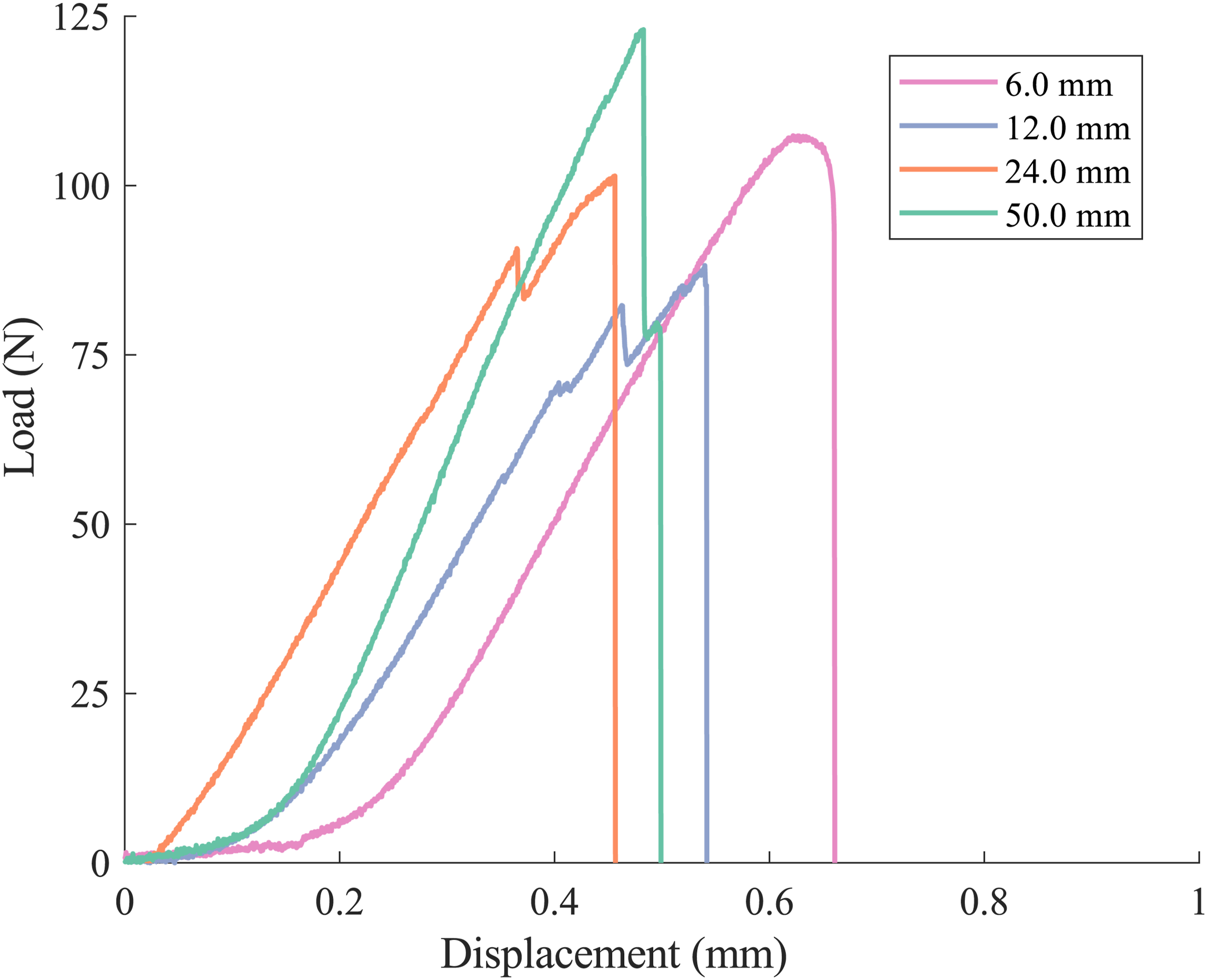
The initial exponential region of the load–displacement curve corresponds to the straightening of the fibre, while the subsequent sudden load drop marks fibre fracture. The displacement at fracture varied within ±0.1 mm, likely attributed to minor in-plane bending of the fibres introduced during the 3D printing process. Post-testing visual inspection consistently revealed that specimens with embedded lengths of 6 mm and above experienced clean fibre fracture within the unsupported gauge region. In contrast, all samples with embedded lengths of 5 mm or less predominantly exhibited slippage, often accompanied by remnants of fibre left within the matrix. This systematic failure mode distinction provides the empirical basis for assigning the 6 mm transition threshold used in this study.
As shown in Figure 4, a consistent increase in peak load with embedded length is evident, suggesting that the interfacial bonding area plays a dominant role in load transfer efficiency. For embedded lengths of 12 mm and above, the curves display a steeper slope and higher stiffness prior to fracture, indicating reduced fibre–matrix interfacial compliance. Moreover, the abruptness of the load drop at failure becomes more pronounced with increasing embedded length, characteristic of fibre-dominated failure without significant interfacial yielding or progressive debonding.
Interestingly, the curve corresponding to the 6 mm specimen shows a more gradual load drop post-peak, hinting at possible mixed-mode failure or partial debonding preceding fibre fracture. This observation may suggest that the transition point between slippage and clean fracture lies between 5 and 6 mm, reinforcing the critical length threshold previously identified. Future studies employing in-situ imaging techniques, such as micro-CT or digital image correlation, could provide valuable insight into the evolution of local damage and fibre–matrix interactions across this transition.
Figure 5 presents the load–displacement curves for representative specimens exhibiting fibre slippage, observed in all cases with embedded lengths of 5 mm or less. This failure mode consistently followed a four-stage progression: (i) initial bonding and fibre alignment, (ii) interfacial debonding initiation, (iii) catastrophic debonding, and (iv) frictional sliding. Representative load—displacement curves illustrating carbon fibre slip for several embedded lengths.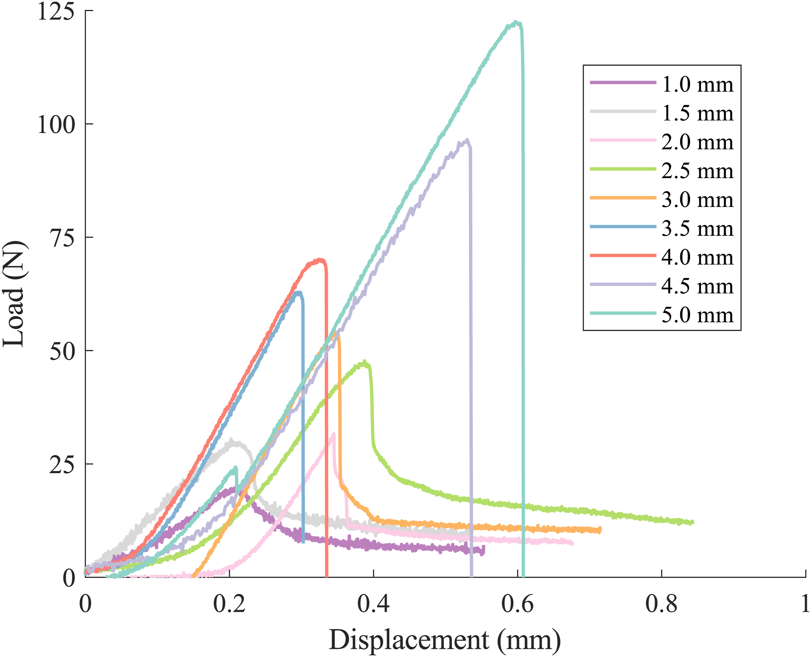
During the initial stage, the carbon fibre straightens under tensile load, often producing a non-linear or delayed exponential increase in force due to residual in-plane waviness from the printing process. This is followed by a relatively linear load increase, representing elastic load transfer through an intact fibre–matrix interface. At a critical load, a sudden deviation from linearity marks the onset of interfacial failure. The subsequent peak corresponds to the point of complete debonding, beyond which the adhesion rapidly deteriorates.
Post-peak, a second regime emerges where load is carried primarily by frictional resistance between the debonded fibre and the surrounding matrix. This is characterised by a gradual decline or plateau in load, as seen in curves corresponding to 3.0 mm and 4.0 mm embedded lengths. Notably, longer embedded lengths within this slippage regime (e.g., 4.5 mm and 5.0 mm) demonstrate higher peak loads and more pronounced plateau regions, indicating increased energy dissipation during sliding. In contrast, shorter lengths (e.g., 1.0–2.0 mm) show early debonding and lower overall load capacity, reflecting insufficient interfacial area for effective stress transfer.
The multi-stage nature of these curves highlights the complex interfacial behaviour under partial bonding conditions and underscores the critical role of embedded length in governing not only peak load but also post-debonding frictional response. These findings support the identification of a transition region between 5 mm and 6 mm embedded lengths, beyond which fibre fracture becomes dominant.
Figure 6 presents the relationship between peak load and embedded length for all tested specimens, clearly delineating two distinct interfacial failure regimes. For embedded lengths between 1 mm and 5 mm, where fibre slippage dominates, peak load increases linearly with embedded length. This linear correlation is statistically strong, with a Pearson coefficient of r = 0.9725, confirming that interfacial adhesion strength in this regime scales proportionally with bonded surface area. This behaviour is consistent with classic shear-lag models, where stress is transferred along the interface through shear, and failure occurs via progressive interfacial debonding followed by frictional sliding. Peak load versus embedded length, illustrating two distinct failure regimes: slippage (L ≤5 mm), characterized by a linear trend (blue dashed line) with 95% confidence interval (blue shaded region), and fibre fracture (L ≥6 mm), where peak loads plateau at 99.67 N (red dashed line) with corresponding 95% confidence interval (red shaded region). The inset highlights the linear correlation observed in the slippage regime. These confidence intervals were derived directly from the full scatter of peak-load measurements.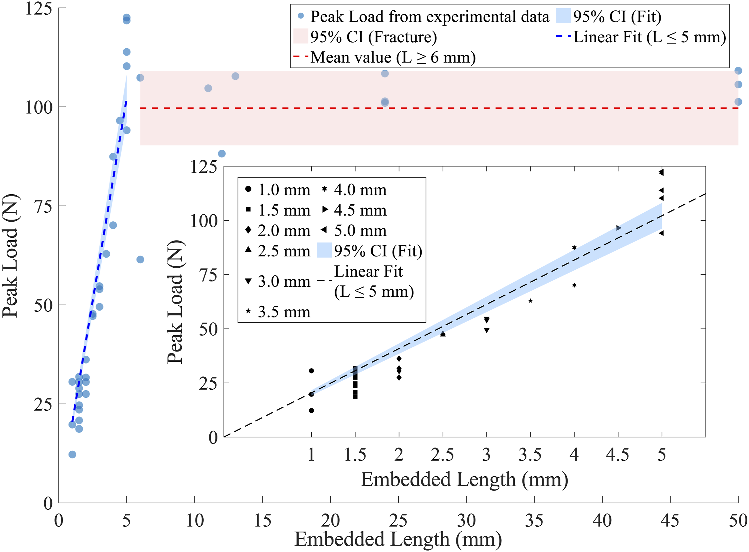
Beyond the transition point at approximately 6 mm, the failure mechanism shifts from interfacial slippage to fibre fracture, and the peak load reaches a plateau around 100 N. The reduced correlation in this region (r = 0.3965) reflects the decoupling of load-bearing capacity from embedded length, as the limiting factor becomes the tensile strength of the carbon fibre rather than interfacial shear strength. This plateau indicates that, beyond a critical length, additional embedded length does not contribute to increased load transfer, as the interface is already capable of fully mobilizing the fibre strength.
Despite the inherent process-induced defects in 3D-printed composites such as fibre waviness, local voids, or incomplete impregnation,42–44 the experimental data exhibit a robust trend, underscoring the repeatability and reliability of the observed transition. The fitted 95% confidence intervals in both regimes further reinforce the statistical significance of the underlying failure mechanisms.
The inset in Figure 6 highlights the linear trend in the slippage regime and suggests a threshold-like behaviour: once a critical embedded length is surpassed, the system transitions from a friction-governed to a strength-governed response. This distinction is critical for design applications involving embedded continuous fibres, as it provides a quantitative criterion for achieving full fibre strength utilisation without overdesigning the interfacial length.
To better capture the underlying physics of the slippage regime, the linear model was constrained to pass through the origin, reflecting the physical expectation that zero embedded length results in zero load transfer. The resulting fit yielded a slope of 20.43 N/mm, with a 95% confidence interval (CI) ranging from 19.24 to 21.62 N/mm, and a coefficient of determination R2 = 0.9244, indicating a strong correlation. In contrast, the fracture regime was modelled as a constant mean value of 99.67 N, with a 95% confidence interval between 90.29 and 109.05 N. These confidence intervals were derived directly from the full scatter of peak-load measurements.
The two regimes are described by the piecewise relationship below, as illustrated in Figure 6:

The critical embedded length, L
c
, represents the minimum fibre length required to achieve effective stress transfer from the matrix to the fibre. It was estimated by equating the peak load predicted by the slippage regime to the mean peak load associated with fibre fracture, as shown in equation (2). This intersection defines the breakpoint in the segmented regression (Figure 6), marking the transition from interface-dominated to fibre-dominated failure.


The calculated value of L c is 4.88 mm, with a 95% confidence interval ranging from 4.34 to 5.42 mm. Ensuring that fibres exceed this critical length is essential to fully mobilise their tensile strength and maximise the reinforcing efficiency in composite structures. In the context of additive manufacturing, knowledge of L c can guide the optimal placement of reinforcing elements: short fibres with lengths below 15 L c act as discontinuous reinforcements, while lengths above this threshold (L >15 L c ) can be classified as continuous fibres. This distinction provides a useful design guideline for fibre architecture in 3D-printed composites, especially when tailoring mechanical performance at the mesoscale.
In short or discontinuous fibre composites, where L < L c , fibres contribute minimally to load transfer, often debonding or pulling out before reaching their full tensile capacity. 45 For L > L c , fibres can sustain greater load fractions and are more likely to fracture before interfacial failure, although full stress transfer is not achieved at the fibre ends (within approximately L c /2 of the tips). To fully mobilise the reinforcing potential, the embedded length should significantly exceed L c , typically by at least 5L c . However, excessively long fibres (≫ 5L c ) yield diminishing mechanical returns and can introduce manufacturing complexities and costs.46,47 Therefore, accurately determining L c is essential for optimising fibre efficiency, improving stress transfer, and guiding the design of high-performance composites, particularly in additive manufacturing. 48
This concept extends directly to additively manufactured continuous fibre composites. 49 Knowledge of L c enables informed fibre path planning, ensuring that locally embedded fibre segments maintain lengths above the critical threshold even in complex geometries. Strategic fibre placement in three-dimensional space—accounting for curvature and local stress variations—can preserve effective load transfer throughout the structure. Such tailored spatial fibre orientation ultimately enhances mechanical performance, stiffness, and material efficiency in 3D-printed composites.50,51
Apparent interfacial shear strength
Fundamentally, the critical embedded length is governed by the strength of adhesion at the fibre–matrix interface, quantified by the interfacial shear strength (IFSS). The IFSS defines the maximum shear stress that the interface can withstand before debonding. A higher IFSS promotes more efficient stress transfer, thereby reducing the critical length required for effective fibre reinforcement. The IFSS can be estimated from the experimental slippage data by analysing the proportional relationship between peak load and embedded length, following the classical formulation proposed by Kelly and Tyson
52
:

The interfacial shear strength (IFSS) was estimated from the slope of the linear relationship between peak load and embedded length in the slippage regime, following equation (6):

Thus, the apparent interfacial shear strength, defined here per unit nominal tow perimeter, is τIFSS = 18.6 ± 1.2 MPa.
The measured apparent interfacial shear strength (τIFSS = 18.6 ± 1.2 MPa) falls within the expected range for carbon fibre-reinforced thermoplastic composites. However, it is important to recognise that IFSS is influenced by multiple factors intrinsic to the material system and manufacturing process.
Surface roughness and chemical compatibility between the carbon filaments, the thermoset sizing layer, and the PETG matrix play a critical role in interfacial bond formation. Because the carbon tow contains a thin thermoset impregnation layer, load transfer occurs through a multi-stage pathway, first from the PETG matrix to the thermoset interlayer, and subsequently from the thermoset to the carbon filaments, rather than across a single direct PETG–carbon interface. Accordingly, the reported IFSS should be interpreted as an apparent effective value governed by adhesion across this hybrid interface and by the degree of thermoset–PETG wetting achieved during co-extrusion. Unlike in conventionally manufactured composites, where the fibre sizing chemistry is relatively stable, the elevated thermal and shear conditions in extrusion-based AM may modify, partially degrade, or disrupt the sizing layer, thereby weakening interfacial bonding and promoting premature interfacial failure.
The estimation of IFSS in 3D-printed composites using the present pull-out model relies on several classical assumptions. The fibre is assumed to be uniformly embedded along its entire length, with continuous adhesion and complete wetting by the surrounding matrix. The interfacial shear stress is assumed to be uniformly distributed at the point of failure, and end effects near the fibre tips are neglected, following conventional simplifications in pull-out modelling. 52 It is further assumed that the effective fibre diameter after printing remains consistent with the nominal diameter of the input filament tow. Under these assumptions, analysis of specimens exhibiting fibre slippage yields an apparent IFSS of 18.6 ± 1.2 MPa (95% CI).
In the present co-extruded bi-matrix tow, impregnation is most complete near the tow perimeter, while the core contains partially wetted or dry filaments. Consequently, the nominal diameter used in equations (5) and (6) should be interpreted as an effective tow diameter, and the resulting IFSS represents a tow-scale average rather than a local shear stress acting uniformly on each filament.
Moreover, printing-induced defects such as partial impregnation, interfacial voids, and local fibre misalignment are expected to reduce the effective IFSS. These imperfections act as stress concentrators and promote premature interfacial debonding, particularly under tensile loading. Thermal history also plays an important role: residual stresses arising from thermal contraction during cooling may either enhance or degrade adhesion, depending on the mismatch in coefficients of thermal expansion between fibre and matrix. In addition, the layer-by-layer deposition strategy inherent to additive manufacturing can introduce anisotropy in interfacial properties. Therefore, given the non-ideal conditions characteristic of additively manufactured composites, both the reported IFSS and the corresponding critical embedded length (L c ) should be interpreted as effective values that reflect the combined influence of fibre morphology, matrix behaviour, and process-induced imperfections.
The measured IFSS value for the manufactured PETG/CF composites reflects a relatively strong interfacial adhesion, likely facilitated by adequate wetting during the composite co-extrusion process. The estimation of IFSS serves as a valuable benchmark for assessing interfacial quality across different material systems and processing routes.53,54 Furthermore, it provides a quantitative target for optimising printing parameters to further enhance fibre–matrix bonding in future 3D-printed composite designs. Comparison with literature data supports the validity of the adapted pull-out test method. For example, Touchard et al. 20 reported an IFSS of 19.9 ± 5.2 MPa for carbon fibre-reinforced PA6 composites fabricated via material extrusion, based on fibre fragmentation testing. Similarly, Tóth et al. 55 estimated an IFSS of 7.2 MPa for short carbon fibres (8 mm length) embedded in a PLA matrix, also produced through additive manufacturing. The close agreement between our measured IFSS and values reported for similar thermoplastic composites underscores the reliability of the experimental methodology employed and confirms its suitability for characterising interfacial strength in 3D-printed composite systems.
Further microstructural evidence supporting the mechanical observations is provided by SEM analysis of the cross-sections of tested specimens. Figure 7 presents representative images of the two primary failure modes: fibre fracture and fibre slippage. In Figure 7(a), corresponding to fibre fracture, remnants of the PETG matrix are visible adhering to the fibre surface, suggesting effective wetting during the composite co-extrusion process. However, the image also reveals incomplete impregnation towards the core of the fibre bundle, where matrix penetration appears insufficient. For imaging purposes, the fibre was intentionally sectioned to expose the fracture interface. The fractured surface exhibits a rugged morphology with fibre fragments embedded within the surrounding matrix, consistent with cohesive failure occurring within the fibre rather than purely at the fibre–matrix interface. Representative SEM images illustrating the two failure modes observed in tested specimens: (a) fibre fracture with matrix remnants and (b) fibre slippage with a clean interfacial cavity.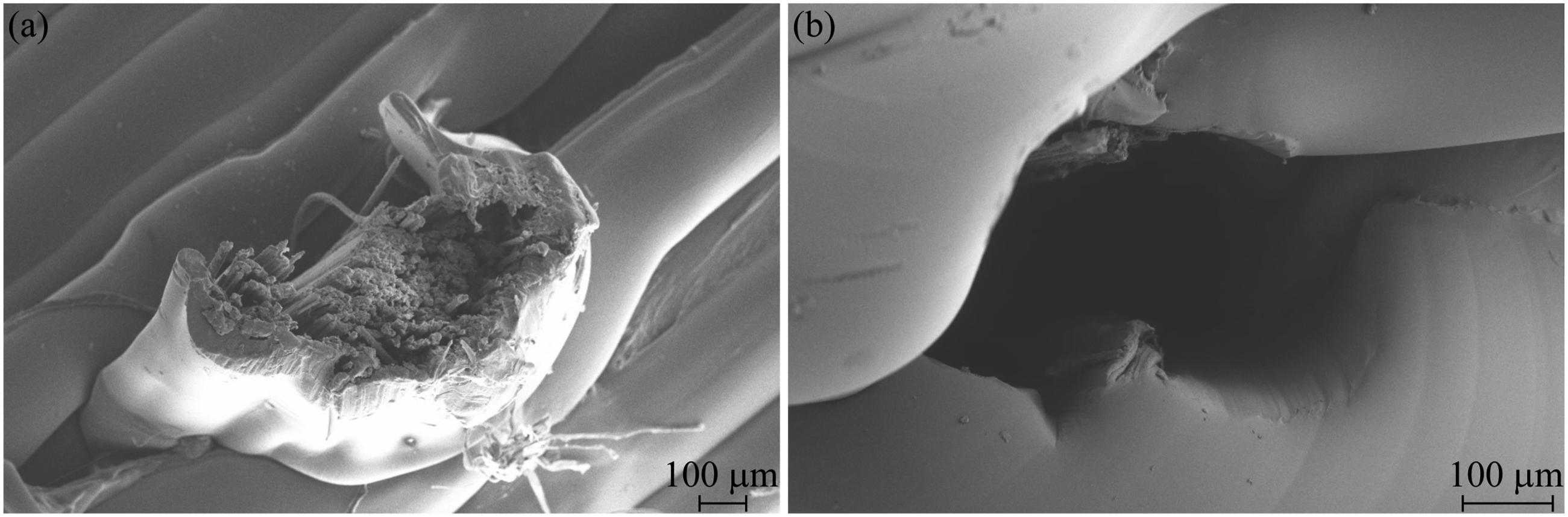
The observed incomplete impregnation toward the core of the fibre bundle is consistent with known challenges in co-extrusion 3D printing of continuous fibre composites.45,56,57 During printing, high matrix viscosity, insufficient pressure, and/or rapid printing speeds can limit the ability of the polymer to fully penetrate the fibre bundle, leading to the formation of dry regions. These unimpregnated areas reduce the effective load transfer capability and promote premature failure by acting as internal stress concentrators. Addressing these process-induced defects through optimised printing parameters or tailored matrix rheology remains an important avenue for improving interfacial performance in additively manufactured composites.
The microstructural evidence provides a compelling explanation for the lower-than-expected fracture loads recorded during mechanical testing. Although the manufacturer specifies an ultimate tensile load of approximately 212 N for the carbon fibre filament, premature failure likely originated from dry, unimpregnated regions within the core of the fibre bundle. These unsupported internal fibres act as stress concentrators, promoting localised crack initiation and subsequent propagation across the bundle. Such internal defects undermine the effective tensile capacity of the composite and precipitate early fibre fracture. This failure mechanism closely resembles the classical sword-in-sheath mode described in composite fracture literature, where external fibres are well bonded but internal fibres remain weakly supported. These observations support the earlier assumption that only the outer filaments participate fully in interfacial load transfer, validating the use of an apparent, tow-scale IFSS definition.
In contrast, Figure 7(b) depicts the failure surface of a specimen that underwent fibre slippage. The cavity left by fibre pull-out appears smooth and clean, with minimal matrix deformation or fibre residue, indicating that failure predominantly occurred at the fibre–matrix interface. The polished nature of the void suggests that, following interfacial debonding, frictional sliding became the dominant load transfer mechanism. These distinct microstructural signatures not only corroborate the mechanical test observations but also reinforce the interpretation of two distinct failure regimes based on embedded length and interfacial adhesion strength.
In addition to acting as stress concentrators, variations in local fibre support and bonding create uneven stress distributions, concentrating tensile and shear stresses in poorly impregnated zones. These heterogeneities promote the earlier onset of crack initiation and facilitate unstable crack propagation, further contributing to the premature failure of the composite. 56 As such, the observed sword-in-sheath behaviour is not solely a result of insufficient impregnation, but also of complex internal stress redistributions arising during mechanical loading.
Despite the valuable insights obtained in this study, several limitations should be acknowledged. First, the calculation of IFSS and the critical embedded length is based on simplifying assumptions,58,59 including uniform fibre embedding, complete matrix wetting, and constant fibre diameter, which may not be fully satisfied due to inherent variability in the additive manufacturing process. Second, minor deviations in fibre alignment and realised embedded length during fabrication and post-processing can introduce measurement uncertainty, particularly for specimens with shorter embedment lengths. Third, while effective for isolating interfacial behaviour, the pull-out test does not capture the complex multiaxial loading conditions or fibre–fibre interactions experienced in structural components. Additionally, although SEM analysis provided useful microstructural insight, it was performed on a limited number of specimens and may not fully reflect the variability across the printed composite population.
Finally, while the observed scatter in peak-load values and subsequent statistical analysis quantify specimen-level variability, the relationship between mechanical response and underlying defect morphology remains qualitative in this study. Volumetric defect quantification and direct defect–property correlation are therefore identified as important directions for future work, but were beyond the intended scope of the present investigation.
Future studies could address these limitations by incorporating in situ imaging during mechanical testing, larger statistical sample sets, micro-computed tomography (micro-CT) to quantify internal void content and impregnation quality (e.g., 45), and advanced numerical modelling to simulate interfacial failure under complex loading conditions. Such integrated experimental and computational approaches would further advance understanding of interfacial behaviour in additively manufactured continuous fibre composites.
Moreover, although printing parameters were held constant in this study to isolate the effect of embedded length, the results can also be interpreted within a broader process–structure–property framework for continuous fibre additive manufacturing.
Key parameters such as nozzle temperature, print speed, and layer height directly influence polymer viscosity, fibre wetting, and impregnation quality, and thus interfacial adhesion. For instance, higher extrusion temperatures generally enhance wetting by reducing matrix viscosity, 60 whereas excessive print speeds may reduce residence time within the co-extrusion chamber and promote the partially impregnated fibre regions observed in SEM Figure 7(a). 61 Previous studies have shown that nozzle temperature contributes the largest share of variability in interlaminar shear strength, followed by print speed and layer height. 9 Although these parameters were not varied here, the measured IFSS and the observed transition between slippage and fracture regimes provide a baseline for future parameter-driven optimisation of fibre–matrix bonding in composite fibre co-extrusion.
Estimation of interfacial fracture energy
Beyond peak load and IFSS characterisation, the interfacial fracture energy (G
c
) was estimated to provide an energy-based measure of fibre–matrix adhesion. The fracture energy was calculated by integrating the area under the load–displacement curve up to complete pull-out and normalising by the embedded fibre surface area, following:
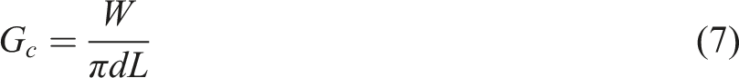
For a representative specimen with d = 0.35 mm and L = 4.0 mm, the integrated area under the load–displacement curve was measured to be approximately 120 N ⋅ μm. Converting to Joules:

The corresponding embedded fibre surface area is:

Thus, the interfacial fracture energy is calculated as:

This value reflects the energy required per unit area to fully debond the fibre from the matrix, capturing both interfacial adhesion and frictional sliding contributions.
Fitted cohesive zone law
Based on the estimated apparent IFSS (τmax = 18.6 MPa) and the calculated interfacial fracture energy (G
c
= 27.3 J/m2), a linear traction–separation cohesive law was fitted to characterise the fibre–matrix interface. Assuming a triangular cohesive law shape, the critical separation (δ
c
) corresponding to complete interfacial decohesion is obtained as:
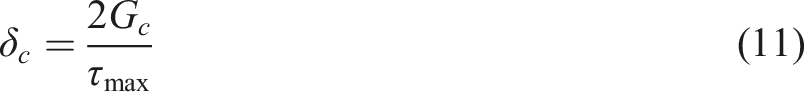
Substituting the experimental values:

Thus, the proposed cohesive law parameters are: • Maximum interfacial shear strength: τmax = 18.6 MPa • Critical separation: δ
c
= 2.94 μm
These parameters can be used to model progressive interfacial debonding in finite element simulations of 3D-printed continuous-fibre composites, providing a physics-based representation of interfacial failure mechanisms.
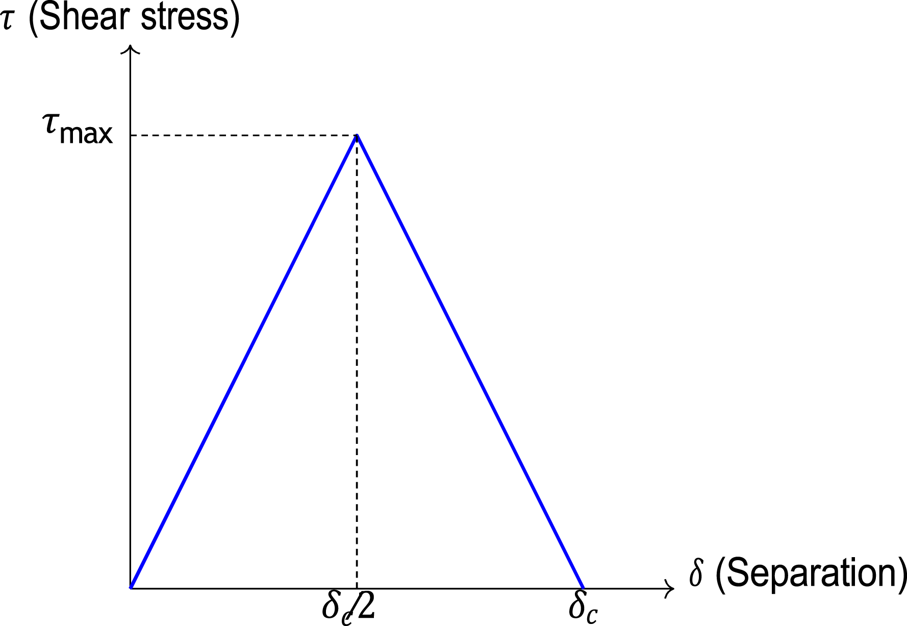
To visualise the fitted interfacial cohesive behaviour, a schematic traction–separation curve is presented in Figure 8. The model assumes a linear elastic increase in shear stress up to the maximum interfacial strength (τmax), followed by linear softening until complete decohesion at the critical separation (δ
c
). This idealised law provides a simple yet effective representation of interfacial failure based on the experimentally determined G
c
and IFSS values. Schematic representation of the fitted linear traction–separation cohesive law for the fibre–matrix interface, characterised by maximum shear stress τmax and critical separation δ
c
.
The cohesive law parameters derived here can serve as a foundation for finite element models aimed at simulating interfacial failure and fibre pull-out phenomena in additively manufactured composites.
While a linear traction–separation law was adopted in this study for simplicity and analytical tractability, it represents an idealised approximation of the interfacial debonding process. In practice, fibre–matrix interfaces in co-extruded continuous-fibre composites often exhibit progressive damage, non-linear softening, and gradual loss of load transfer due to partial impregnation, heterogeneous contact, and printing-induced defects. More advanced cohesive formulations, such as bilinear or exponential traction–separation laws, could potentially capture this gradual interfacial degradation and post-peak softening behaviour more accurately. However, implementation of such models requires additional independently measured interfacial parameters that are not currently available for this system. The linear law, therefore, provides a physically meaningful first-order description of the dominant interfacial response, while more complex cohesive representations will be explored in future work.
Statistical analysis of pull-out strength
To assess the variability in interfacial adhesion strength across specimens, a Weibull statistical analysis was conducted on the extracted peak pull-out forces. Figure 9 presents the Weibull probability plot. A strong linear correlation (R2 = 0.91) was observed, indicating that the pull-out strength distribution can be reliably described by a two-parameter Weibull model. The extracted Weibull modulus was m = 1.81, suggesting moderate scatter in interfacial performance. The characteristic peak load (σ0), corresponding to a 63.2% failure probability, was determined as 74.25 N. Weibull probability plot of the pull-out peak forces for 3D-printed continuous carbon fibre–reinforced PETG composites. The fitted Weibull modulus is m = 1.81, and the characteristic peak load is σ0 = 74.25 N (R2 = 0.91).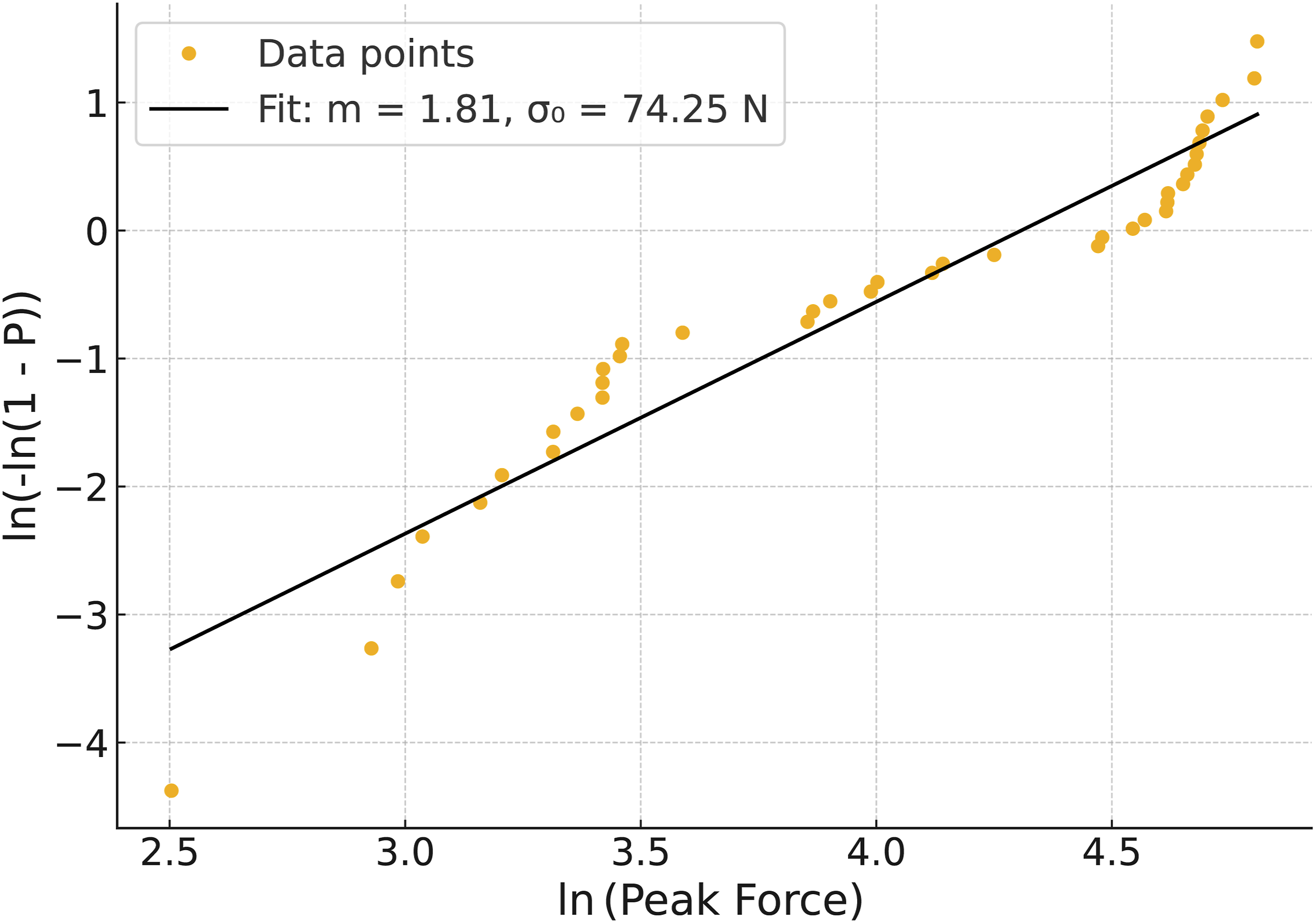
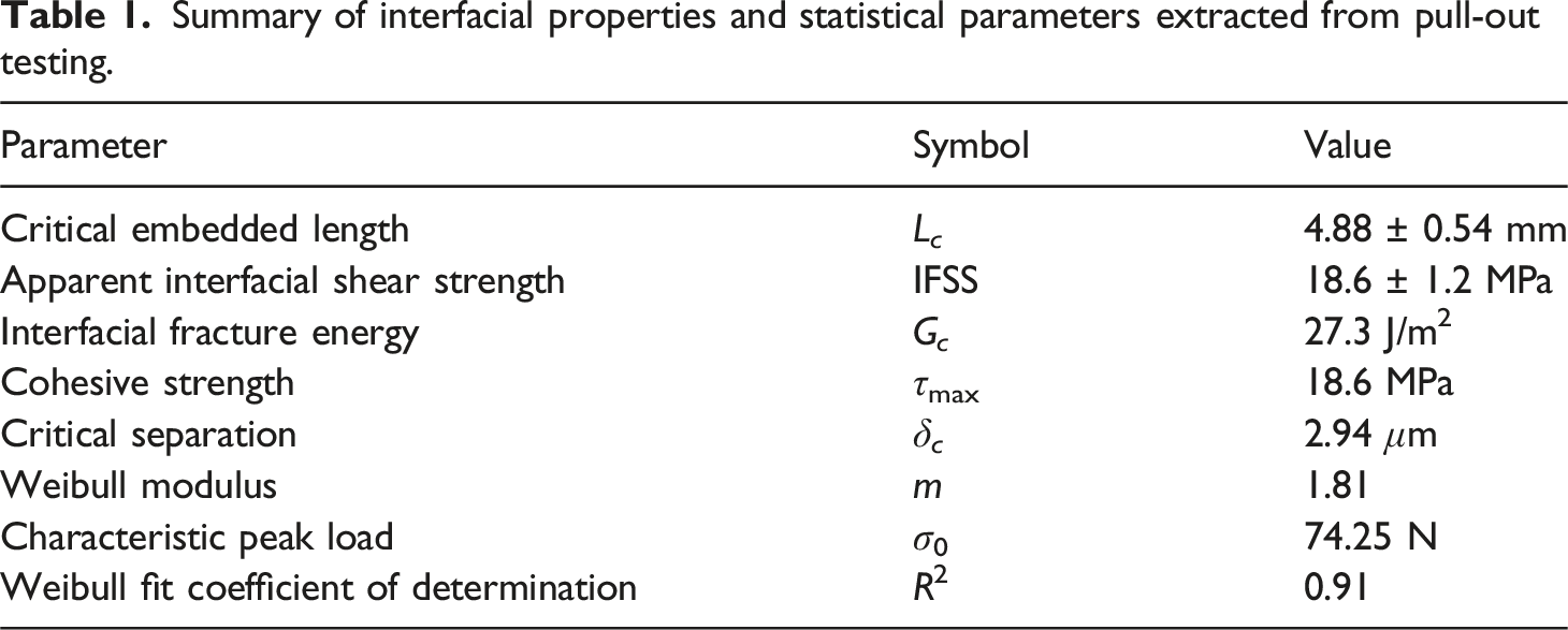
Summary of interfacial properties and statistical parameters extracted from pull-out testing.
Overall, the experimental characterisation and modelling results presented here establish a coherent understanding of interfacial behaviour in 3D-printed continuous fibre composites, forming the basis for the conclusions to be drawn in this study.
Conclusions
This study investigated the influence of fibre embedded length on the interfacial adhesion behaviour of continuous carbon fibre-reinforced PETG composites manufactured via composite fibre co-extrusion through tensile pull-out testing, fracture energy estimation, and cohesive law fitting. Based on the experimental and modelling results, the following conclusions are drawn: • Two distinct failure regimes were identified depending on embedded length: fibre slippage dominated for L ≤5 mm, while fibre fracture became predominant for L ≥6 mm, with a critical embedded length (L
c
) determined to be 4.88 ± 0.54 mm [95% CI]. • The apparent interfacial shear strength (IFSS) was measured as 18.6 ± 1.2 MPa, and the interfacial fracture energy (G
c
) was estimated to be 27.3 J/m2, providing complementary stress- and energy-based characterisations of fibre–matrix adhesion. • A linear traction–separation cohesive law was fitted based on IFSS and G
c
, establishing parameters for future finite element modelling of interfacial failure in additively manufactured composites. • The adapted pull-out methodology and combined mechanical–microstructural analysis provide a reliable framework for characterising, optimising, and modelling interfacial behaviour in 3D-printed continuous fibre composite structures.
Overall, this study provides the first experimentally validated critical embedded length and cohesive interfacial parameters for continuous fibre co-extrusion additive manufacturing, establishing a quantitative benchmark for future fibre placement strategies, interface modelling, and the development of structural design guidelines for printed continuous fibre composites.
Future research will focus on extending this methodology to explore the effects of fibre surface treatments, matrix modifications, and process-induced defects. Integration of in-situ mechanical testing, high-resolution imaging (e.g., micro-CT), and cohesive zone modelling is envisioned to advance the predictive design of lightweight structural composites.
Footnotes
Acknowledgements
We also thank Kari Kolari (VTT), Siddharth Jayaprakash, and Kirsi Kukko (Aalto University) for valuable discussions on the experimental setup concept.
Declaration of conflicting interests
The authors declared no potential conflicts of interest with respect to the research, authorship, and/or publication of this article.
Funding
The authors disclosed receipt of the following financial support for the research, authorship, and/or publication of this article: This work was supported by the Strategic Research Council as part of the ValueBioMat project (Grant No. 352429).
Data Availability Statement
The data will be made available from the corresponding author upon reasonable request.