
Abstract
Mass production of nanofibers from needleless electrospinning shows great potential in research and development of nanofibers. However, how to improve the electrospinning performance so as to achieve high quality nanofibers is still of great challenge. In this study, airflow has been applied to optimize upward needleless electrospinning from ring spinneret. Effects of airflow speed and the position of airflow on the nanofiber quality and production rate have been investigated. It has been found that thinner and more uniform nanofibers were produced when airflow was applied to needleless electrospinning system. It also improved the collected nonwoven membrane, resulting in better nanofibrous structure of the as-spun nanofibers. Application of airflow on needleless electrospinning would further benefit the development of mass production of nanofibers from needleless electrospinning.
Introduction
Nanofiber has been a research focus since 1990s due to its application potential in diverse areas [1,2]. Electrospinning is regarded as the most widely used method in producing nanofibers due to its simplicity, effectiveness, and applicability to different kinds of polymers available in today’s industry market [3]. In order to scale up the production rate of nanofibers from electrospinning, researchers have focused on needleless electrospinning [4–8]. However, the fiber quality from needleless electrospinning may not be as good as that from needle electrospinning due to insufficient evaporation of solvent or unstable whipping process. How to ensure the quality of as-spun nanofibers when the production rate has been enhanced greatly is important for further development of needleless electrospinning. Effort has already been put on modifying traditional electrospinning to achieve better fiber quality or novel fiber structure [9–14]. Among these modification methods, airflow showed evident improvement on needle electrospinning [12–14]. The gas jackets on needle were applied to stabilize the Taylor Cones and control the transition from electrospray to electrospinning resulting particle-to-fiber [12]. Gas flow modified electrospinning has been reported to produce thinner and uniform nanofibers [13]. Besides, weak tangential airflow has been applied to electrospinning to produced crimped and waved electrospun nanofibers [14].
For needleless electrospinning, a huge number of polymer jets are produced at the same time. Use of airflow may accelerate the evaporation of the solvent or attenuate the jets further, and thus the collected fiber morphology together with productivity may be different. It is of great importance to apply airflow on needleless electrospinning so as to improve the as spun fiber quality and improve the production process. Based on previous studies on needleless electrospinning [5,8], airflow has been applied to optimize upward needleless electrospinning from a ring in this study. Effects of airflow speed and the position of airflow on the nanofiber quality and production rate have been investigated thoroughly. Application of airflow on needleless electrospinning would further benefit the development of mass production of nanofibers from needleless electrospinning.
Experimental
Materials
Polyvinyl alcohol (PVA; average molecular weight 146,000–186,000, 96% hydrolyzed), obtained from Aldrich-Sigma, was used as the model polymer. PVA solutions (9 wt%, 810 cP) were prepared by dissolving the PVA powder in deionized water at 90℃, with intensive stirring for about 12 h and without adding any additives in the solution.
Airflow modified needleless electrospinning
The apparatus for the needleless electrospinning from ring comprises a high voltage power supply, a feeding system as shown in Figure 1a and a collector. A rotating ring made from copper wire was used to pick up polymer solution from the polymer reservoir; the rotating speed was set as 40 r/min. The ring shape was set as length = 16 cm; ring diameter = 8 cm, and wire diameter = 2 mm. The polymer solution was connected to a high voltage power supply (ES100P, Gamma High Voltage Research) via an inserted electrode in the reservoir; conventional applied voltage was set as 60 kV. An aluminum plate was used to collect the nanofibers with a collecting distance of 13 cm.
Airflow modified needleless electrospinning with airflow applied (a) through the center of the ring coil, (b) along the spinning way, and (c) on the collector.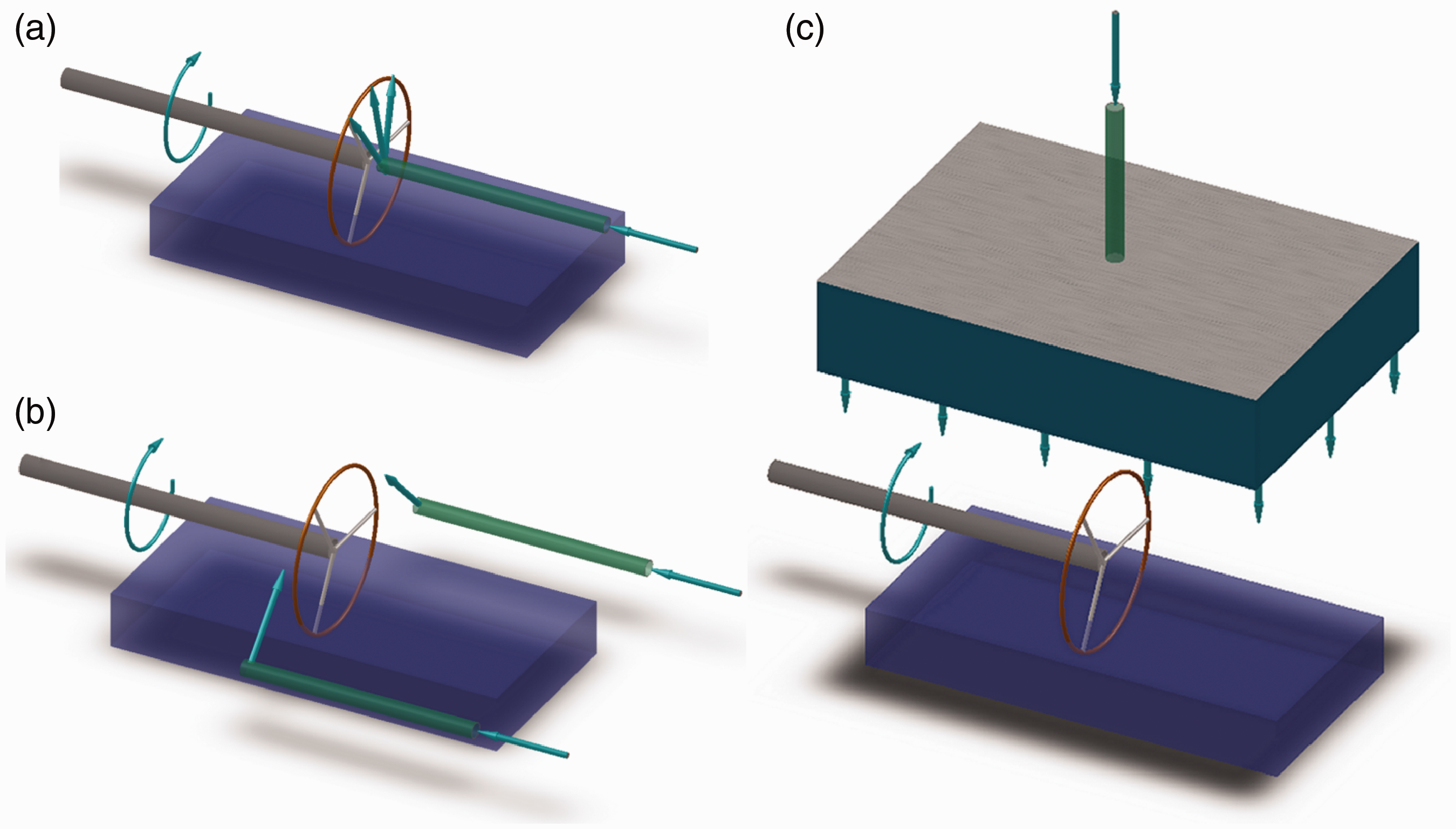
Airflow was applied to reinforce the wire coil needleless electrospinning using the ring coil as spinneret under standard conditions (21 ± 2℃, relative humidity (RH) 65 ± 5%). The airflow was applied alternatively to modify the generation, whipping process, or collection of needleless electrospinning. Firstly, the airflow was inserted in the center of the ring wire, as shown in Figure 1a. The airflow tube was sealed at the end and located exactly along the central axis of the ring with the end situated in the center of the ring circle. A small slit was made by partly cutting the tube at the cross-sectional direction, thus the airflow was distributed in a pie slice area with a central angle of 90°. The airflow was then passed through the slit to blow the top arc of the ring to modify the produced polymer jets. The flow speed of the airflow can be controlled by changing the pressure of the flow between 10 and 20 lbf/in2. Secondly, instead of locating in the center of ring, two airflow tubes were set 5 cm away from the ring with the airflow direction tangential to the ring (as shown in Figure 1b) to supply airflow on the top of the ring. The exerted airflow along the spinning way modified the whipping process of polymer jets on the top of the ring. Finally, airflow was just exerted into a purpose-built box which, with mesh covered on one facet as collector, was used as collector (as shown in Figure 1c). The exerted airflow blows the collected nanofibers so as to accelerate the evaporation of solvent.
Characterizations and measurements
The fiber morphology was observed under a scanning electron microscope (SEM, Leica S440). The average fiber diameter was calculated from the SEM photos with the aid of image analysis software (ImagePro + 4.5). More than 100 fibers were tested from at least four SEM photos that were taken from different areas of a given sample. Results were averaged and the standard deviation was calculated to show the diameter distribution range. Production rate was tested by weighing the collected fibers in every 10 min.
Results and discussion
Airflow in the center of the ring
When no airflow was added to the needleless electrospinning, the as-spun nanofibers membrane showed an uneven membrane with transparent parts located in the nonwoven membrane. Handle of the as-spun nanofibers membrane before and after airflow was exerted suggested that a dryer membrane was obtained when airflow was applied.
Figure 2 shows the SEM photos with different magnifications (×2000 and ×10,000) of the as-spun electrospun nanofibers. When no airflow was inserted into the center, nanofibers tend to stick into each other. Because the solvent of the previously collected nanofibers was unable to evaporate totally, new fibers targeted onto the same position and thus many fibers accumulated into blocks as shown in Figure 2a. A detailed view in Figure 2a' shows the fibers stick into each other at the cross points, forming an interconnected web.
SEM photos of nanofibers with different airflow (center of the ring) pressure: (a) and (a') control; (b) and (b') 10 lbf/in2; (c) and (c') 15 lbf/in2; (d) and (d') 20 lbf/in2. Bar = 2 µm (PVA 9%, applied voltage 60 kV, collecting distance 15 cm). PVA: polyvinyl alcohol; SEM: scanning electron microscopy.
When airflow was applied to the center of the coil, fewer blocks were formed on the as-spun nanofiber mats, as shown in Figure 2b'–d'. A clear fibrous structure has been obtained and the nanofibers are isolated from each other. The interconnected network is due to the insufficient evaporation of solvent during the whipping and collecting processes. Airflow blew the evaporated solvent, moisture in this case, to ambient areas and thus the air around the nanofibers was not saturated with solvent anymore so further evaporation could happen. Moreover, the forced convection by the airflow favored the evaporation process of solvent from the nanofiber in its forming stage. It is estimated that use of airflow in the center of the ring releases the collected nanofibers from sticking into each other.
Figure 3a shows the fiber diameter and its standard deviation of the as-spun nanofibers, and the inset of which shows the diameter distribution when airflow with pressure of 10 lbf/in2 is applied. Obviously a narrower distribution of fiber diameter with smaller mean diameter around 200 nm has been achieved when airflow was applied. The diameter of as-spun nanofibers concentrates around 200 nm from the inset, suggesting more uniform nanofibers have been collected. Further thinner fibers with smaller standard deviation are observed with the increase of flow speed as shown in Figure 3a. However, ANOVA analysis showed the means of data with different air pressure were not significantly different. Thus increase of airflow pressure did not bring further thinning effect to the as-spun nanofibers. When airflow was applied in the center of the ring coil, the formation of polymer jets was affected by the exerted flow and the airflow might stretch the polymer jets to some extent so that the as-spun nanofibers were thinner and more uniform. It was evident that the protrusion of polymer solution from the ring surface was affected by the exerted airflow, which might attenuate the protrusion to a sharper cone. Besides, the airflow provided further attenuating force to the polymer jets so that the jets withstood stronger force for attenuation. Finally, the accelerated evaporation process resulted in thinner fiber diameter.
Effect of airflow (center of the ring) pressure on the fiber diameter (a), diameter distribution (10 lbf/in2) (inset of (a)) and productivity (b) of as-spun nanofibers (PVA 9%, applied voltage 60 kV, collecting distance 15 cm). PVA: polyvinyl alcohol.
Figure 3b shows the productivity of nanofibers by applying airflow in the center of the ring. Evidently the productivity drops suddenly when airflow is applied. When the airflow blows the surface of the ring where polymer jets are produced, the surface of the coated solution on the top ring will be modified. Some protruded parts of the coated solution where jets may be drawn out are affected and thus the formation of jets will be diminished. It was noted that when the pressure of airflow is 20 lbf/in2, most polymer solution was thrown out because of the blowing. Polymer solution blocks were observed by eyes on the collector and thus the productivity was higher.
Airflow along the spinning way
Figure 4 shows the SEM photos of nanofibers electrospun from needleless electrospinning with airflow is applied along the spinning way. Compared to nanofiber without modification of airflow in Figure 2a, these nanofibers show better fibrous structure with fewer fibers interconnected and few blocks. Magnified photos show very even nanofibers were produced and most of the fibers are isolated from others.
SEM photos of nanofibers with different airflow pressure (along the spinning way): (a) and (a') 10 lbf/in2; (b) and (b') 15 lbf/in2; (c) and (c') 20 lbf/in2; (d') bar = 2 µm (PVA 9%, applied voltage 60 kV, collecting distance 15 cm). PVA: polyvinyl alcohol; SEM: scanning electron microscopy.
It is obvious that applying airflow along the spinning way can improve the nanofibrous structure from interconnection. It definitely accelerates the evaporation speed of the solvent of polymer jets and thus the nanofibrous structure is improved. This is the same as airflow in the center of the ring coil. However, increase of the airflow pressure shows less impact on the structure of nanofibers as seen from SEM photos in Figure 4. Airflow along the spinning way cannot affect the fiber formation process as the fiber attenuation takes place immediately after the generation of polymer jets.
Fiber diameter analysis results of the as-spun nanofibers are shown in Figure 5a, it is evident that applying the airflow along the spinning has no impact on the fiber diameter. The as-spun nanofiber diameter is a little bit coarser than that of control, and the diameter is almost the same with the increase of airflow pressure. ANOVA analysis showed the means of data with different airflow pressure were not significantly different, suggesting no evident thinning effect on as-spun nanofibers by increasing air flow pressure. As airflow applied along the spinning way, very thin nanofibers may be blew away in the process of whipping, thus the mean diameter is larger compared with control.
Effect of airflow (along the spinning way) pressure on the fiber diameter (a) and productivity (b) of as-spun nanofibers (PVA 9%, applied voltage 60 kV, collecting distance 15 cm). PVA: polyvinyl alcohol.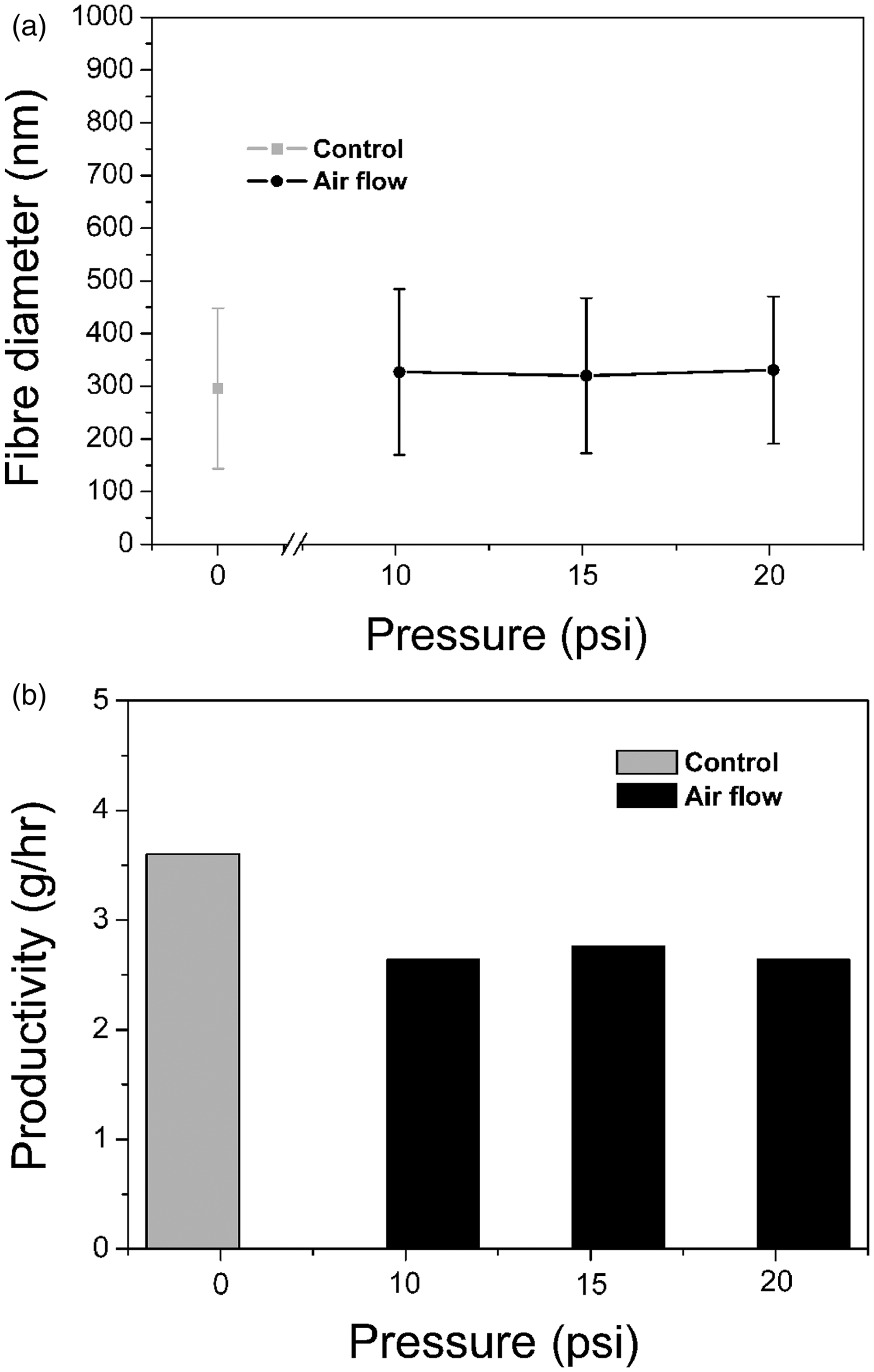
Productivity of needleless electrospinning with airflow along the spinning way is shown in Figure 5b. The productivity is lower than that of the control, and the productivity shows no much difference with the increase of airflow pressure. Airflow exerted along the spinning could not enhance the productivity as it did not affect the generation of polymer jets on the surface of spinnerets. Slight decrease in productivity is due to the evaporation of more solvent from the as-spun nanofibers and the blowing effect on the spinning way that make lighter and shorter fibers flied away rather than targeted onto the collector.
Airflow at the collector
Airflow was also applied at the collector and the SEM photos of the collected nanofibers are shown in Figure 6, the fiber diameter analysis together with fiber productivity is shown in Table 1. The structure of the collected nanofibers is improved evidently as seen from the SEM photos. This is also due to the acceleration of the evaporation of polymer solution solvent after airflow is applied.
SEM photos of nanofibers. Control (a) and (a'); collected with airflow on the collector (b) and (b'). Bar = 2 µm (airflow pressure 15 lbf/in2, PVA 9%, applied voltage 75 kV, collecting distance 18 cm). PVA: polyvinyl alcohol; SEM: scanning electron microscopy. Fiber diameter and productivity of needleless electrospinning before and after airflow was applied to the collector (applied voltage 75 kV, collecting distance 18 cm).

Since the airflow at the collector has no affection on either the ring surface or the electric field, the fiber diameter together with diameter distribution of nanofibers is almost the same as that of the control. The productivity also kept stable when airflow was employed at the collector. Since higher collecting distance (18 cm) was chosen in this case, the productivity was much less than other cases discussed before.
It has been found that positioning of airflow is crucial in improving the as-spun nanofiber quality and productivity. Comparing the three methods of applying airflow in needleless electrospinning, the most efficient way of improving the nanofiber quality is to apply airflow in the center of the spinneret. The other two methods can isolate the nanofibers to some extent, but show no evident effect on thinning of as-spun nanofibers. Unlike airflow modified needle electrospinning, airflow shows no enhancement on the productivity of needleless electrospinning.
Conclusions
Airflow can be positioned either in the center of the ring spinneret or along the spinning way and at the collector to modify the upward needleless electrospinning. It showed improvement on the nanofibrous structure of the collected nanofibers. The collected nanofibers isolated from each other while that without airflow showed interconnected fibrous structure. Thinner and more uniform nanofibers were obtained when the airflow was fixed at the center of the ring but the productivity decreased at the same time as the jets formation was affected by the airflow. Airflow showed no evident improvement on the productivity of nanofibers when it was positioned along the spinning way and at the collector.
Footnotes
Funding
Funding supports from National Natural Science Foundation of China (Grant No. 51103109), Innovative Team of Hubei Collaborative Center for Textile Key Technology, and Research Funding from Wuhan Textile University, China are greatly appreciated.