
Abstract
The paper introduces a novel clamp adapter with the goal to improve the quality of the tensile test setup for high-modulus multi-filament yarns. Common tensile test machines damage the yarns initially or prematurely due to non-uniform load introduction which causes stress concentrations. As a result, the theoretical yarn strength (perfectly clamped filaments at a unique length and no initial damage) is underestimated. With the new clamp adapter, higher strengths close to the theoretical values can be measured since the adapter largely eliminates the problems with non-uniform load introduction. A test series comparing yarns strengths tested with the clamp adapter and with commonly used test methods has been performed and the results are discussed in this paper. Furthermore, they are compared with theoretical values using the Daniels’ fibre-bundle model.
Introduction
The steadily growing application of high-modulus multi-filament yarns has evoked intensive efforts to improve the quality and reproducibility of strength characterization for this type of material [1–3]. In contrast to traditional yarn materials like cotton and polyester, high-modulus yarns made of glass, carbon or aramid are very sensitive to stress concentrations due to their brittleness when loaded in tension. At the same time, they exhibit a pronounced strength size effect due to the presence of randomly distributed flaws along the yarn. Both these properties make the use of traditional setups for yarn tensile testing difficult as discussed in Section ‘Traditional yarn tensile test setup’.
This paper introduces a new tensile test device: a clamp adapter for the tensile test machine Statimat 4U [1] (referred to as ‘Statimat 4U adapter’ further in the text), which significantly reduces the problem of stress concentration in the clamps compared to the current tensile test setups on the one hand (Section ‘New tensile test setup’). On the other hand, the test introduces a well-defined test length and can therefore be used to measure the effect of length on the yarn strength.
The basic concept of the test setup is the separation of the clamping function from the stress homogenization function at the ends of the test length. Thanks to the introduction of the homogenizing clamp into the semi-automated Statimat 4U machine, several test series with a large number of samples for varied test lengths and yarn materials could be performed. In order to assess the quality of the data, comparative tests using the traditional setups have been done in parallel. The results of the comparison are presented in Section ‘Comparison of test setups’.
The fact that the new testing device could measure generally higher values of strength compared to the current techniques raised the question, whether or not the measured strength is close to the level theoretically achievable for the measured material. Using the theoretical framework of statistical size effect, we have performed the analysis of the correspondence between the known strength of single filaments and the strength of a yarn for carbon and AR-glass. The results of the analysis are shown and discussed in Section ‘Filament and yarn strength’ and conclusions are drawn in the last section.
Traditional yarn tensile test setup
Two categories of methods that are currently being used for introducing the tensile load into a high-modulus multi-filament yarn in order to measure its tensile strength are outlined below:
Load transfer using deflection and friction
The first category uses mechanical fixing clamps and an additional deflection of the yarn which introduces the load to the yarn through friction. The deflection reduces the force which has to be taken up by the fixing clamps. An example of this method is the test with capstan grips [2,4,5], where the yarn is deflected or twisted around a spool (see Figure 1).
Uniaxial tensile test with capstan grips on a dry yarn – Zwick Roell AG (left); embedding the porters in resin (right) – specimens can be tested with any tensile test machine (ITA, RWTH university, Aachen, Germany).
In some cases, the tests are semi or even fully automatic (Statimat 4U with ‘big bollards’ [1]) which is a great advantage of this test method. However, the method also has some disadvantages. Due to the radii of the deflection elements, the minimum test length of the specimen is limited. Furthermore, the test length of the yarn is not precisely defined since the force is introduced over a certain length at the deflection elements. Since the yarn strength is length dependent (see equation 5), the test length needs to be known for the interpretation of the yarn tensile properties. The main disadvantage, however, is the non-uniform stress among the filaments which arises because filaments directly contacting the spool carry more of the introduced load.
Load transfer using resin porters
For the second category of methods, the yarn ends are embedded in resin blocks which are then used for the load introduction (Figure 1). An example of resin porters for testing AR-glass yarns can be found in earlier studies [3,6].
State of the art for tensile test methods.

New tensile test setup
To avoid stress concentrations in yarns at the clamps during the tensile test, a new device has been developed, which separates the functions of yarn fixation and of stress homogenization into two pairs of clamps (Figure 2). The device was realized as a plug-in clamp for the Statimat 4U tensile test machine [1].
Statimat 4U adapter (left) with the newly developed clamp (detail). Stress along a tested yarn 
Tensile tests performed with this newly developed clamp proceed in the following steps:
The outer ‘fixation clamps’ (FCs) clamp the yarn with a pressure p0 and introduce a fraction of the axial force F0 so that the yarn experiences the tensile stress The yarn gets compressed by the inner ‘homogenization clamps’ (HCs) with soft polyurethane contact layers with the pressure pHC and an additional axial force FHC corresponding to the yarn stress The load is increased correspondingly to a given control strain rate while keeping the force difference between the FCs and HCs constant (see Figure 2(c)).
In this way, the yarn is not damaged by the HCs defining the test length since the majority of the tensile force is introduced by the outer FCs. The HCs combine lateral pressure via a soft contact layer with a moderate axial force. The lateral force homogenizes the stress in filaments by intensifying the inter-filament friction and the axial force increases the probability of filament breaks within the test length. Note that the test length is, contrary to the deflection-friction tests, defined as the distance between the HCs. The deflection of the yarn around the bollards between the HCs and FCs has a similar function as the HCs – it takes up a part of the load due to friction and can be used in addition to the HC to diminish damage in the FCs.
In contrast to the standard clamping with bollards (Section ‘Load transfer using deflection and friction’), the control parameters (e.g. the additional axial force introduced by the HCs, lateral pressure of both the FCs and HCs) of the adapter clamps can be adjusted to achieve best results for a given material. If, for example, a yarn consists of brittle filaments with rather large cross sections, they will be more prone to rupture due to the lateral pressure of the homogenizing clamp which, in this case, should be kept low in order to best balance the trade-off between homogenization of stresses within the yarn cross section and the initial filament damage.
Comparison of test setups
Comparative tensile tests have been performed between the new Statimat 4U adapter (Section ‘New tensile test setup’) and the reference setup realized by one of the two traditional test methods (Section ‘Traditional yarn tensile test setup’). Three different materials were tested. All the tests have been loaded at the equal strain rate of 1.7%/min.
Material:AR-glass yarns 1200 tex (Saint-Gobain Vetrotex Deutschland GmbH) Reference method:resin porters (Section ‘Load transfer using resin porters’) and capstan grips (Section ‘Load transfer using deflection and friction’) Test lengths: 50, 70, 110, 160, 230, 340 and 500 mm (for both test methods) Material:E-glass yarns 1200 tex (PPG Industries, Inc.) Reference method:resin porters (Section ‘Load transfer using resin porters’) Test lengths: 50, 70, 110, 160, 230, 340 and 500 mm (Statimat 4U adapter) 50, 110, 160, 230 and 500 mm (resin porters) material: carbon 400 tex (Toho Tenax Co., Ltd.) reference method: Statimat 4U big bollard clamps (Section ‘Load transfer using deflection and friction’) test lengths: 35, 70, 130, 250 and 500 mm (for both test methods)
The test lengths were chosen, if possible, in a way that they appear equidistant in logarithmic scale. For the AR-glass tests, a randomized experiment was performed. Initial material biases caused by fluctuations in strength due to the position of the test sample within the spool were eliminated by a random specimen choice. That means, specimens taken from the spool in an ordered manner were assigned the parameters length and test method randomly. Using the design of experiments wording [8], a block randomized comparison experiment with one factor of two levels (test method) was performed. The overall sample size was 280 specimens (2 levels of the factor test method, 7 blocks – test lengths, 20 replicates per block). The measured response variable was the strength. The remaining two comparative experiments (E-glass and carbon) were not randomized, and the number of replications for each combination of test parameters was 20.
The results of the comparative experiment in terms of mean strength and COV (coefficient of variation) are summarized in Figure 3 and Table 2. Table 2 depicts the measured values and statistical significance of the hypothesis testing (H0: Test results: yarn strength measured with Statimat 4U adapter and reference methods. Results of the comparative experiments for AR-glass 1200 tex (reference: resin porters), E-glass 1200 tex (reference: resin porters) and carbon 400 tex (reference: Statimat 4U, big bollards). COV: coefficient of variation.

Discussion
Figure 3 shows that the mean tensile strengths measured with Statimat 4U adapter were for all three materials and all test lengths higher than the reference values. A lower level of significance for the
It seems that the differences in mean strengths for E-glass and carbon become smaller for longer test lengths in general. This effect is probably due to the increased influence of the statistical size effect which predicts lower strengths for yarns at longer test lengths because of the higher probability of severe flaws [7]. The reduction of yarn strength due to stress concentrations in the clamps is constant and independent of the test length. With larger test lengths, however, the probability of a cluster of severe flaws in the yarn structure grows. The strength of a long yarn is thus likely to be rather determined by the weakest spot along the test length than by the stress concentration in the clamps.
Filament and yarn strength
Based on the results obtained using the new test setup exhibiting a lower reduction of strength compared to the traditional methods, an interesting question can be raised concerning the theoretical correspondence between the strength of filaments and the strength of the yarn. Indeed, if the measured yarn strength approaches the theoretically achievable strength, then it might be possible to reproduce the predictions given by the statistical fibre-bundle models.
In this section, we address the yarn strength reduction due to statistical scatter in filament breaking strain which is due to the random nature of flaws within the material structure and relate it to the obtained test results.
Theoretical yarn strength
Since a filament is only as strong as its weakest cross section, the weakest link model can be applied to evaluate its breaking strain. This model idealizes the filament as a chain of links with varying strength, which have to withstand the applied load for the whole chain to survive. Weibull [9] established a robust theory on the probability distribution of strength of such a structure which describes the minimum extreme of a left bounded distribution, i.e. the strength of the weakest of a set of links. This distribution is known as Weibull distribution and its application to fibre-breaking strain ξ, i.e. the probability of failure of a filament of length L subjected to strain ɛ reads

Given that the filaments have a unique (deterministic) modulus of elasticity Ef and their constitutive law is linear elastic up to the brittle rupture at the strain ξ, the filament strength can be written as
Theoretical filament and mean bundle equation (4) stress–strain diagrams (a); theoretical mean filament strength equation (3) and mean bundle strength equation (5) as a function of gauge length (b).

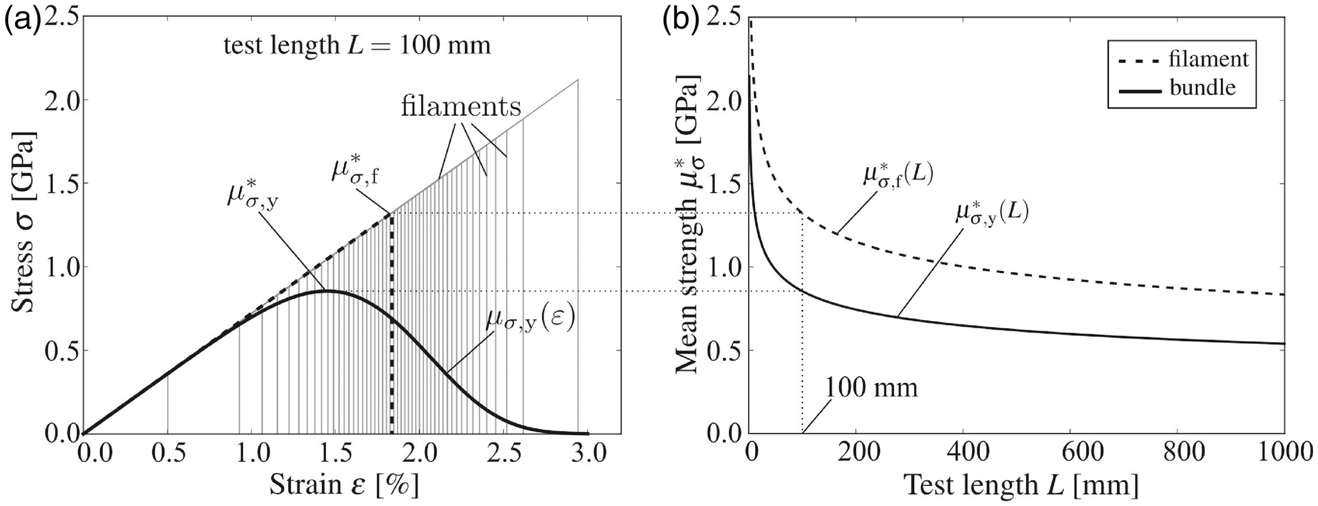
The analysis of the strength of a yarn which consists of parallel brittle filaments with random strength is based on the work of Daniels [10]. This work has been reviewed and extended with further effects relevant to a multi-filament yarn many times since earlier works [7,11–16]. One of the important conclusions of Daniels’ derivations is that for asymptotic bundles (i.e. consisting of an infinite number of filaments – applicable for bundles with several hundred filaments), the mean value of the bundle stress as a function of bundle strain is


This reduction of strength is generally inherent to fibre bundles with scatter in breaking strain of individual filaments due to micro-scale flaws and cannot be influenced by enhancing the testing equipment. The only way to diminish this source of strength reduction is to produce filaments with more homogeneous material structure.
Comparison with theoretical bundle strength
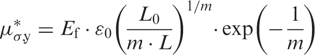
Equations derived in Section ‘Theoretical yarn strength’ can be utilized to evaluate the theoretical bundle strength at any test length when the filament strength distribution at the given test length is known. Equivalently, the bundle strength can be evaluated when the mean filament strengths at different test lengths are known [7] (Figure 5). This computation can also be performed inversely, so that the filament strength distribution at any test length can be evaluated when the mean bundle strengths at different test lengths are given (Figure 5).
Scaling of filament strength (solid line) and bundle strength (dashed line) based on filament tests (triangles) compared with measured bundle strengths (Statimat 4U adapter and reference method).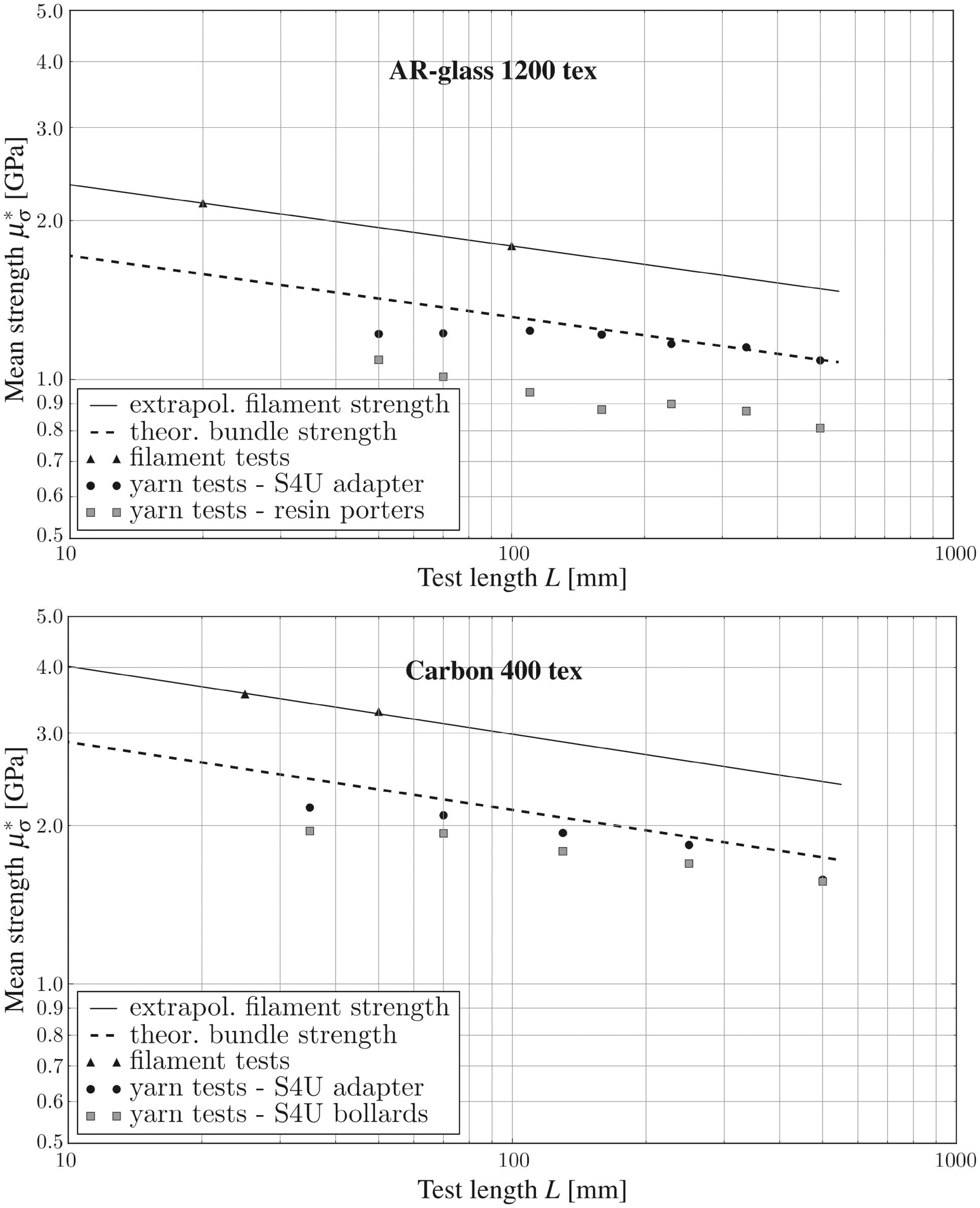
Let us remark that the reduction of strength for bundles compared to single filaments is in this model caused only by the scatter in filament strength, so that the difference between model prediction for bundle strength and measured values (in the range of test lengths corresponding to the bundle behaviour [15]) can be related to imperfections of the test method. A prediction of the theoretical bundle strength (Figure 5, dashed lines) based on the mean filament strength (Figure 5 triangles, measured with FAVIMAT testing device [1]) was evaluated and compared with bundle measurements described in Section ‘New tensile test setup’ (Figure 5 filled circles) for AR-glass and carbon. Filament tests for E-glass were not available at the time this article was written. If the filament tests can be assumed to be unbiased, the predicted bundle strength (Figure 5 dashed line) fits the measured values of the yarn strength (Figure 5 filled circles) fairly well for larger lengths. Compared to the same yarn tested with the reference method (Figure 5 grey squares), it is obvious that the Statimat 4U adapter delivers strengths much closer to the theoretical bundle strength, which assumes a perfect clamping and thus the damage due to clamping of the Statimat 4U adapter can be considered very low.
The discrepancy between model and experiments for shorter test length (≤ 100 mm) is due to filament waviness and differences in filament lengths. At short yarn lengths, these minor geometrical inaccuracies become more pronounced and cause non-uniform strain distribution across the yarn. More detailed explanations are given by Vořechovský and Chudoba [7].
Conclusions
The newly developed tensile test device Statimat 4U adapter largely diminishes stress concentrations in high-modulus yarns with brittle filaments and thus measures higher strengths than other tensile test methods. Both a comparative experiment and theoretical models based on single filament tests confirm the better performance of the new device with a high statistical significance. A combination of the improved testing method for bundles, tests on single filaments, and the fibre-bundle model describing the statistical size effect provides an efficient means for thorough strength characterization of high-modulus multi-filament yarns.
Concerning other materials, the positive effect of the adapter clamp could not be observed for aramid, Ultra high molecular polyethylene (UHMPE) and basalt yarns, which have been tested in smaller sample sizes. However, significant differences compared to reference methods were measured for a small sample size of coated carbon yarns (9% polymer matrix). The positive effect of the Statimat 4U adapter on the yarn strength can thus be expected mostly for yarns with very brittle fibres, or generally, fibrous structures prone to local stress concentrations.
Footnotes
Funding
This work has been supported by the German Science Foundation under project number SFB 532 T05 ‘Development of an experimental and numerical methodology for the characterization of high-modulus multi-filament yarns’. This support is gratefully acknowledged.