
Abstract
In this research, loop-formed fiber is introduced as a novel reinforcement method of soil composites instead of using ordinary fibers. In order to investigate the materials' mechanical properties, the shear behavior of both fiber and looped-fiber-reinforced soil composites was analyzed by micromechanical method (finite element method) and a set of direct shear tests. The results indicate that the looped-fiber soil composite exhibits greater failure strain energy compared with fiber-reinforced soil composite at the same fiber orientation in the substrate. Furthermore, the proposed model demonstrated two major reinforcing components: “the fiber effect” and “the loop effect.” The latter effect is the key benefit and the main advantage of using looped fibers over ordinary fibers in soil reinforcement. Altogether, there is a close agreement between finite element method outputs and experimental results, suggestive of a novel technical textile material that could potentially be used in geotechnical engineering.
Introduction
A comprehensive literature review shows that using natural and/or synthetic fibers in geotechnical engineering is feasible in fields such as pavement layers (road construction), retaining walls, earthquake engineering, railway embankments, protection of slopes, and soil-foundation engineering [1].
Fiber-reinforced soil structures have been conventionally designed using composite approaches to characterize the contribution of fibers to stability. In these cases, the mixture is considered as a homogenous composite material. The contribution of the fibers has been typically quantified by an equivalent friction angle and cohesion of soil [2]. Therefore, composite models have been proposed by several investigators including mechanistic models [3–5], a statistical model [6], and an energy-based limit analysis model [7].
Models based on a volumetric homogenization technique but limited to the description of non-linear elastic behavior have been presented by Ding and Hargrove [8] for monotonic loading and by Li and Ding [9] in cyclic loading conditions. A complete constitutive law for soils reinforced with continuous filament (Texsol) has been presented by Villard et al. [10] and Prisco and Nova [11], employing the superposition of sand and fiber effects. Villard’s model is the only one that recognizes the importance of fiber orientation as a parameter governing the effectiveness of fiber inclusion. In another work, a two-dimensional distinct element method has been developed for the micromechanical analysis of mixtures of granular materials and flexible fibers [12]. Numerical analysis with finite difference code has been performed by Babu et al. [13]. Some researchers extended the shear lag theory proposed by Cox [14] to explain the role of fiber length and fiber diameter in short fiber soil composites. Thus, it was found that the compressive strength of the composite soil improves by increasing the fiber length and deceasing fiber diameter [15]. In another work, Diambra et al. [16] presented a model based on the rule of mixtures of composite materials at conventional triaxial soil tests. The model considers that the fibers behave linear elastically and the soil, when unreinforced, obeys the simple linear elastic perfectly plastic Mohr–Coulomb model. In addition, Abtahi et al. [17] have reported using artificial neural network to predict the role of fiber parameters on shear strength of short fiber soil composites.
It is important to know that lack of scientific standards, clumping (local aggregation) and balling (folding of fibers) of fibers, and adhesion of fiber to soil are the three major executive problems involved with short-fiber soil composite production. In this manner, fiber lengths beyond 2 in. (51 mm) did not improve soil properties significantly and proved more difficult to work with both in laboratory and field experiments [1,18].
On the other hand, since composite structures with soft-material matrix do not have adequate pullout resistance with flat-type reinforcements such as fibers, there are increasing cases where reinforcements with passive resistance are used in conjunction [5,19]. Therefore, in this research, loop-formed fiber is introduced as a novel reinforcement method for soil composites instead of ordinary fibers. On the whole, this article introduces a new technical textile material that can be potentially commercially attractive in geotechnical engineering. Mainly, soils mixed with randomly distributed fibers can be used as patches in the localized repair of failed slopes, soil protection, and/or wall stabilization, and hence the shear strength of fiber-reinforced soil would be considered an important concept [20].
Materials and methods
Preparation of treatments
Physical and mechanical properties of the soil used in this study.

Physical and mechanical properties of PE-reinforcing elements.

Fiber length.
PE: polyethylene.
Primary evaluations demonstrated that the prepared welded geogrids include the same longitudinal and transverse properties, i.e. they are square technical fabrics.
The percentage of open area (POA%), an important property to describe geogrids, was calculated using equation (1)
(a) Schematic of a geogrid element and (b) looped (left) and ordinary (right) PE fibers used in this study.

Determination of input parameters for micromechanical analysis
Fiber diameter df is an important input parameter to predict shear improvement of fiber and/or looped fiber-reinforced soil composite. Therefore, microscopic method with zoom of 40 was used to measure df and rib widths of geogrid samples accurately. The results are shown in Table 2.
The elastic modulus of geogrid samples was measured according to ASTM D 6637 using an Instron Tensile Tester (Zwick universal testing machine 1446 60, 1994, Germany). The test was carried out in accordance with the constant rate of elongation (CRE) method using gage length of 300 mm and the strain rate of 30 mm/min.
The important input parameter for micromechanical analysis is coefficient of friction between PE fiber and soil µ, which is generated by the contact of two surfaces. A novel single fiber pull-out test method was used to assess this property. The Instron Tensile Tester was modified to provide fiber pull-out test through the soil matrix. Initially, soil was poured into a cylindrical mold made from PVC with diameter of 15 mm and height of 40 mm. A hole (D = 4 mm) was entrenched on the mold, 15 mm above the horizon. More details can be found in the study of Hejazi et al. [5]. On the base of optimum moisture content (OMC) (13.82%), the soil should be statically compacted in the mold to fill 30 mm of the mold. Second, to prevent evaporation of moisture, the specimens should be wrapped immediately with plastic membrane, prior to testing. Consequently, a single PE strand (30 mm length) was placed within the soil matrix through the hole and compacted using a small hammer. The embedded fiber length within the soil matrix was 10 mm in all specimens. The PE strand had been disparted from the original geogrid. Five parallel specimens were prepared for each treatment. The apparatus for single fiber pull-out test is shown in Figure 2. The vertical stress on all samples was 25 kPa, and the speed of the pull-out test was 20 mm/min. It was determined according to the fiber length and duration of the test performed (30–60 s). The index of interfacial shear stress between PE strand and soil matrix is called mean value and was 0.35.
Sketch drawing of the pull-out test (not to scale).
Direct shear test
The shear tests were conducted using a standard, laboratory-direct shear apparatus, following the ASTM D 3080 test method. The specimens were shaped in a cylindrical mold with 20 mm height and 63 mm inner diameter by static compaction at the respective OMC of the soil. The testing was performed at 13.82% OMC, according to ASTM 698.
Three vertical normal stresses (σv) of 49, 98 and 196 kPa were used in order to determine the shear behavior of the soft-matrix composite at different compressive loads. The shear tests were strain controlled at the rate of 1 mm/min. A set of three experimental tests was conducted in order to achieve reproducibility of the selected test method. The results of three different tests for the neat soil were presented in a chart with peak stress on horizontal axis and normal (confining) stress on the vertical axis. A linear curve fitting was made on the test result points, and the intercept of this line with the vertical axis gives the cohesion c, whereas its slope gives the peak friction angle ϕ. Consequently, the corresponding friction angle of neat soil ϕ and cohesion c measured in direct shear was 35° and 19 MPa, respectively.
PE fibers and/or looped fibers were always carefully placed in a regular pattern at approximately equal spacing from each other and from the sides of the shear box. Reinforcing elements were placed in a perpendicular orientation to the shear plane, according to the proposed model in micromechanical analysis. Both shear stress and vertical deformation were recorded as a function of shear or horizontal displacement up to a total displacement of 9 mm. The experimental shear improvement of composite soil ΔSexp(σv) was calculated for each sample at each vertical stress σv using the following equation

Micromechanical analysis
In this section, the shear strength of fiber-reinforced soil composite is analyzed by finite element method (FEM). Direct shear test (ASTM D 3080) was simulated through Abaqus 6.9 software. Micromechanical analysis demonstrated the stress distributed on the soil and reinforcing element, i.e. fiber and/or looped fiber, during the shear of the composite. To identify the deformation of reinforcing element and soil in this model, fiber and soil matrix were modeled as deformable parts, whereas rigid body was used to make displacement around the soil matrix. The contact of reinforcing element with the crossing soil was assumed to be surface-to-surface, based on fiber pull-out test results (μ = 0.35). In addition, the dynamic/explicit solution with the following boundary conditions was used:
The lower half of the soil composite volume was fully fixed in the course of shear loading. The upper half of the soil composite volume was vertically loaded (vertical static stresses of 49, 98 and 196 kPa at different treatments). The upper half of the soil volume was moved with a constant speed of 0.5 mm/s in one direction onto the composite, as suggested in the test specifications.
C3D8R elements were used to mesh the reinforcing element and soil bodies. Drucker Prager property was considered for the soil to describe the failure behavior of the matrix. So friction angle (ϕ = 35°) and cohesion (c = 19 MPa) of the neat soil measured in direct shear test were used for further calculations.
At each treatment, the soil composite was enclosed within a metal mold with a height of 20 mm and a diameter of 63 mm, as described in direct shear test. The results are shown in Table 2. At each vertical stress σv, i.e. 49, 98 and/or 196 kPa, shear strength of each composite soil SFE.comp(σv) and neat soil SFE.neat(σv) were calculated. Consequently, shear strength envelopment of each composite sample ΔSFE(σv) with regard to the neat soil can be obtained through

Results and discussion
Comparison of fiber and looped-fiber performance
Figure 3(a)–(d) shows different aspects of the simulated sample PEG/7/8 (sample number 1 in Table 2) during the course of shear loading. According to the treatment description in Table 2, eight looped fibers and/or discreet grids have been vertically oriented within the soil matrix. Figure 4(a)–(d) shows the simulated sample PEF/7/0.5% (sample number 6 in Table 2) during the shear of the soil composite. In this case, 32 fibers reinforcing the soil matrix have been arranged with the same orientation similar to the grid-reinforced sample PEG/7/8. By comparing these two treatments, it is observed that the horizontal fibers in the case of fiber-reinforced sample do not withstand against shear loading of the soil composite (see Figure 4(b)–(d)). This clearly indicates that only vertical fibers deform and resist with the soil matrix against shearing of soil composite. On the other hand, in the case of fiber-reinforced soil composite, the reinforcing phenomenon is related to the performance of vertical fibers. Figure 3(b)–(d) demonstrates that both vertical and horizontal fibers forming loop elements and/or discreet grids are involved in shear resistance of loop-formed fiber-reinforced soil composite. At this stage it can be concluded that pullout resistance of loop-formed fibers has two major components: (a) the friction between soil matrix and vertical elements of looped fiber (the fiber effect) and (b) shear resistance of soil matrix within the loop (the loop effect). Therefore, the total improvement in shear strength of soil composite (ΔSt) can be written in the following format [5]
FEM results of looped fiber-reinforced soil composite under shear loading at σv = 98 kPa: (a) the sample after loading and (b–d) deformation of reinforcing elements during the shear of the composite. FEM results of fiber-reinforced soil composite under shear loading at σv = 98 kPa: (a) the sample after loading and (b, c and d) deformation of reinforcing elements during the shear of the composite. Failure strain energy (J) via time (s) of neat soil (blue line), fiber-reinforced sample (green line), and looped fiber-reinforced treatment (red line).


Shear strength envelopment of treatments
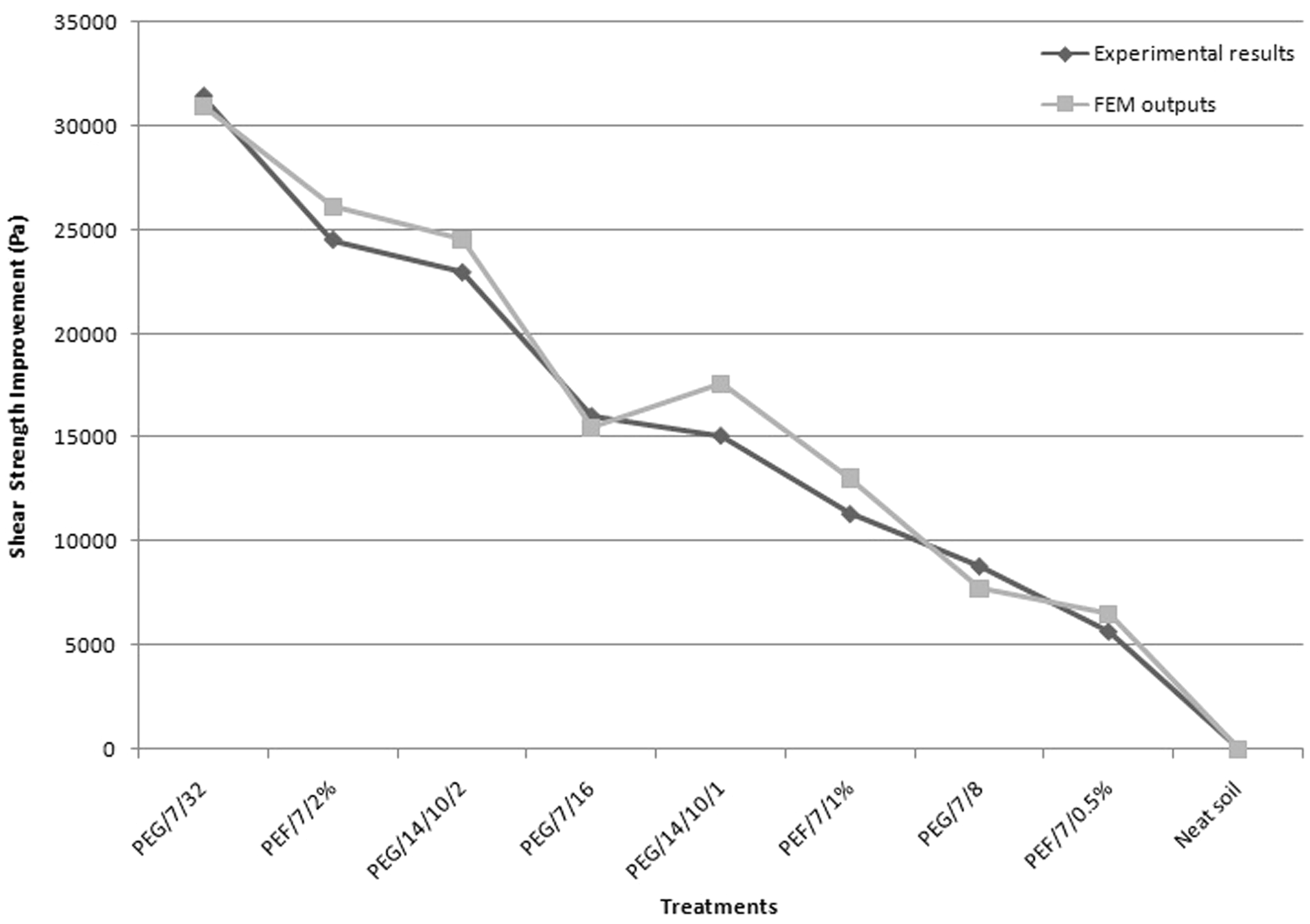
Figures 6–8 show comparison of the experimental results with the model outputs of shear improvement of different soil composite samples at vertical stresses of 50, 100 and 200 kPa, respectively. In general, both fiber and looped-fiber reinforcements increase the ultimate shear strength of composite soils. Regardless of applied vertical stress, shear envelopment of composite soil will increase as the fiber mass fraction enhances (PEF/7/0.5%, PEF/7/1% and PEF/7/2% samples). The same trend can be observed in the case of loop-formed fiber reinforcement at any vertical stress for the PEG/7/8-, PEG/7/16- and PEG/7/32-treated fibers. It is clear that the presence of more fibers extending across the shear plane creates more reinforcing effect. On the basis of the proposed model, under shearing, fiber reinforcement contributes to the increase of shear resistance by mobilizing tensile stress within fibers.
Shear strength improvement of different treatments at σv = 49 kPa (comparison of FEM outputs and experimental tests). Shear strength improvement of different treatments at σv = 98 kPa (comparison of FEM outputs and experimental tests). Shear strength improvement of different treatments at σv = 196 kPa (comparison of FEM outputs and experimental tests).

Additionally, with the increase in vertical stress σv from 50 to 200 kPa, the shear strength improves (Figures 6–8). In order to understand the results, it is necessary to give a short explanation about the stress transfer mechanism in short fiber composites. According to Shao et al. [21], the transferred stress from matrix into the fiber surface in a short-fibre composite can cause an interfacial shear stress τ between fiber and matrix and consequently induces a tensile stress σ within the fiber. It is suggested that during extension, the slippage effect occurs near both ends of the fiber and a central region along the fiber length gripped by the matrix, which is called non-slippage region. If λ is defined as the fiber slippage ratio, which is the ratio of fiber length of the slipping portion to the whole fiber length Lf, the following equation is introduced [21,22]


A set of samples in Table 2 (PEF/7/0.5%, PEG/7/8), (PEF/7/1%, PEG/7/16), and (PEF/7/2%, PEG/7/32) were compared, and it was observed that apart from applied vertical stress σv, the value of ΔS in the case of looped-fiber-reinforced samples is greater than that of fiber-reinforced treatments. As was discussed previously through the presented model, this result might be due to the “loop effect.” Therefore, at the same orientation, fiber content, fiber finesse, and fiber length, looped-form fibers lead to superior reinforcement of the soil compared with ordinary fibers. For instance, the shear improvement value of PEG/7/32 is about 44,603 Pa at σv = 200 kPa; meanwhile, under the same conditions (fiber length, vertical stress, and fiber weight fraction), ΔS is 30,782 Pa in the case of PEF/7/2%, i.e. the loop effect causes approximately 50% increase in shear strength of soil composite.
The loop samples of PEG/1.4/10/2 (number 4) and PEG/1.4/10/1 (number 5) are only different in fiber diameter (Table 2). Figures 6–8 show that sample PEG/1.4/10/2 gives more shear improvement compared with PEG/1.4/10/1 in all tested vertical stresses. This result can be explained through the model proposed by Waldron [23]. In Waldron’s method, the performance of plant roots in shear resistance of soil has been macromechanically modeled using force equilibrium approach. It is supposed that under shearing, plant roots contribute to the increase of soil shear resistance by mobilizing tensile stress σT within the roots. It is proved that σT can be obtained through
The schematic of a plant root within the soil matrix under shear loading.


It seems that the main reason for the difference between simulation and experiments is that in direct shear test, the distribution of vertical stress is not uniform through the shear plane. Therefore, different fibers and/or looped fibers do not deform uniformly. In addition, it is doubtful whether the desired fiber orientation will be retained in the mold after the compaction of the composite soil. Figure 10 shows X-ray computed tomography images of three different looped fibers within the soil matrix after shear loading. The average fiber alignment angle β is about 34o; meanwhile, according to the soil thickness (20 mm) and final shear displacement of soil sample (9 mm), β should be about 24°. One reason may be misalignment of vertical fibers during the compaction process.
X-ray computed tomography images of three different looped fibers within the soil matrix after shear loading.
In this study, vertical fiber orientation was used to reinforce the soil matrix. It does not mean that in the field and/or real conditions, these elements should be aligned vertically within the soil. The loop-formed fibers can be randomly placed within the soil just like ordinary flat-type fibers. In this study, in order to compare experimental results with FEM outputs, we had to use a certain fiber orientation, i.e. vertical orientation. It is emphasized that since fiber orientation plays an important role in shear strength of soil composites, by using randomly distributed fiber orientation, we could not compare experimental results with FEM outputs (see equation (10), the angle of fiber alignment β and its influence on shear strength of soil composite).
Conclusion
The aim of this article was to investigate a novel method to reinforce soil composites by introduction of loop-formed fibers. The looped fibers were prepared by cutting different PE geogrid samples followed by a set of direct shear tests performed on neat, fiber and looped-fiber-reinforced soil composites. Furthermore, the analytical micromechanical model was introduced in order to investigate the performance of fiber and looped-fiber soil composite. The presented model demonstrates that shear resistance of loop-formed fibers has two major components including “fiber effect” and “loop effect.” It was observed that in the case of fiber-reinforced soil composite, the reinforcing phenomenon is related to the performance of vertical fibers; meanwhile, both vertical and horizontal fibers forming loop elements and/or discreet grids are involved in shear resistance of loop-formed fiber-reinforced soil composite. Further FEM analysis showed greater failure in strain energy of looped-fiber soil composite compared with the fiber-reinforced at the same fiber orientations. This concept related to the “loop effect.” “Slippage theory” and “force equilibrium” method were used to explain the experimental and micromechanical results.
Additionally, a coefficient of friction between PE fiber and soil μ, as an important input parameter for micromechanical analysis, was successfully measured through a novel single fiber pull-out test method by modifying the Instron Tensile Tester. In general, the studies open a new window to technical materials development, which might be a potential interest for geological engineering.
In this article, it was shown that in the same fiber mass fraction and fiber orientation, looped fibers provide superior reinforcement of soil compared with ordinary fibers. Therefore, the only imposed cost of producing looped fibers is economically related to grid processing compared with ordinary fibers. For future studies, the use of randomly looped fiber orientation and/or other fiber orientations is also suggested.
Footnotes
Funding
The authors received no financial support for the research, authorship, and/or publication of this article.