
Abstract
In this study, the application of carbon filament yarn (CFY)-based conductive hybrid yarn as the heating element in a textile-reinforced concrete structure is reported. For this purpose, a hybrid yarn having a core-sheath structure (the core is made of carbon filament yarn and the sheath consists of a mixture of short glass and polypropylene fibres) is manufactured by DREF-2000 spinning technique and integrated into textile structure by tailored fibre placement method. Heat can be generated in the concrete structure by passing electric current through the conductive carbon filament yarn core of the hybrid yarn using the principle of resistive heating, where the sheath acts as the protection and isolation layer. From the initial investigations made on a small concrete specimen, important information is gathered and a large concrete slab with integrated conductive hybrid yarn is manufactured. The heat ability and the comfort level of the manufactured concrete slab are measured. The investigations have revealed the potential of using such hybrid yarn for a pointwise heating of the concrete surface for possible appliance in outdoor furniture.
Introduction
Fibre-reinforced cements and concretes (FRC) are firmly established as construction materials. Since the early 1960s, extensive research and development have been carried out with FRC materials, leading to a wide range of practical applications.1–5 With the increase of application areas due to the ease of design with textile-reinforced concrete, the demand for multifunctional concrete is increasing. Using carbon fibre reinforcements, it is possible to design freely shapable delicate and thin structures, combining the positive features of carbon fibres and concrete. Since carbon fibres do not corrode, the normal concrete coverage is not required. As a result, the element thickness drops to only 10–15% of a comparable steel-reinforced concrete structure. This widens the scope of aesthetic and robust architectural design of interior and exterior furniture like benches and chairs, using cementious materials. Due to the high heat conductivity of concrete, the bench/chair exposed to cold weather is not comfortable to be seated on. Therefore, to improve the comfort level, the benches that are exposed to cold weather need to be heated. The aim of this article is to describe the textile technological approaches to integrate heating structures into the textile-reinforced concrete.
The cement matrix is a poor electrical conductor with electrical resistivity of around

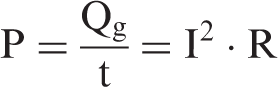
If the electrical energy input is converted into thermal energy generation Qg (J) for time t (s) in concrete, then equation (1) can be written as
Therefore, the materials of heating elements cannot be too low in electrical resistivity, as this results in the resistance of the heating element being too low and a high current capacity of the power source. The materials of heating elements cannot be too high in resistivity either as this results in the current in the heating element being too low (unless the voltage was very high). The upper limit of the resistance depends on the voltage capability of the power source. 14 Therefore, the total resistance of the heating element required to heat a specific area is a decisive factor.
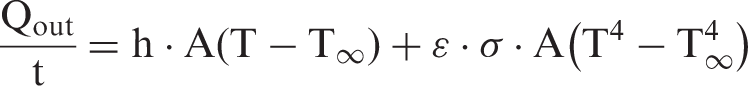
Furthermore, the electrical input power loss due to convection and radiation from concrete surface, termed as energy out Qout can be expressed by equation (3)
The rate of the change in energy store Qst due to temperature change can be expressed by equation (4)


Non-crimp fabrics made of carbon filament (i.e. endless carbon fibre) yarn (CFY) are usually used as the reinforced structure for textile-reinforced concrete, which can also be directly used as the heating element. However, a pointwise heating in a complex shape is not possible. Furthermore, due to the parallel connection of the carbon structure, the resistance is too low and a higher current capacity of the power source is required. An alternative approach of heating concrete could be the integration of heating elements such as commercially available insulated metal wire, which often reduces the handling flexibility to integrate it in a complex geometry onto the carbon-reinforced textile structures. This problem can be overcome by using a conductive and flexible CFY as the heating element separately. However, the CFY should be wrapped with isolating material to avoid short circuit with base-reinforced structure made of CFY during heating by electric current.
Considering these factors, a hybrid yarn having the characteristics of a conductive core and an isolating sheath structure seems to be a well suited option to be used as the heating element. With the DREF-2000 friction spinning technique, it is possible to manufacture the hybrid yarn required as the heating element. Dr Ernst Fehrer developed and commercialized the friction spinning system under the name DREF (DR Ernst Fehrer - DREF) in the 1970s. 16 The invention promoted a renewed interest for the research works and composite industry in core yarns. The DREF-2000 friction spinning machine is one of the latest developments in friction spinning. CFY as the core and hybrid sheath made of glass staple fibres (GF) and polypropylene (PP) fibres is used for manufacturing of the hybrid yarn in this case. The CFY core is the functional element, i.e. the heating component. Electricity will be passed through the CFY in order to generate heat. The function of the sheath is two-fold: first, it protects the core CFY during its integration by stitching with the non-crimp fabric and second, it works as the isolation of the conductive carbon filaments. GF is used mainly as the isolating element and PP is used to improve the process ability and better coverage of CFY.
For the application of the hybrid yarn on the reinforcement structure, tailored-fibre-placement (TFP) technology is used. The advantage of using TFP lies in the fact that the heating element can be placed in the desired point very precisely. Most importantly, TFP also offers damage-free integration of the hybrid yarn onto the reinforcement structure. 17
In the following discussion, the selection criteria of the CFY to be used as the core of the hybrid yarn and the manufacturing of the hybrid yarn to be used as the heating element using DREF-2000 spinning technology is described. Pre-investigations are done on a small concrete specimen with integrated hybrid yarn to gain information about the heating ability of the hybrid yarn. Based on the preliminary investigations, a larger concrete slab with the integrated hybrid yarn is manufactured and the temperature required for the comfort (if one seats on the concrete slab) indoors and outdoors is revealed.
Experimental
Selection of suitable CFY
Characteristics of different CFYs.

CFY: carbon filament yarn.
Production of friction spun hybrid yarn
The hybrid yarn is manufactured on a DREF 2000 friction spinning machine (Fehrer AG, Linz, Austria). In this system, the yarn formation takes place with the aid of frictional forces between rotating drums rotating in the same direction (cf Figure 1(a)). A major advantage of the DREF-2000 friction-spun core yarns is the accurate positioning of the filament at the centre of the yarn cross-section without filament breakage and a desired level of core coverage by the sheath made of short staple fibres.
(a) DREF-2000 friction spinning machine (Fehrer AG, Linz, Austria), (b) sketch and (c) microscopic image of the cross-section and (d) longitudinal view of the FS hybrid yarn produced to be used as the heating element.
Toho Tenax-J HTS 5631 CFY of 800 tex is used as the core component. Total fineness of the sheath is 550 tex, where PP and GF fibres are mixed in the 1:2 ratio. One PP sliver of 4 ktex (9.9 dtex fibre fineness, 64.3 mm length, 27.6 cN/tex and 124.8% breaking elongation) and two slivers of GF of 2 ktex (2.21 dtex, 150–220 mm length, 6.15 cN/tex and 3.5% breaking elongation) are used for the yarn sheath. The core sheath volume ratio of the manufactured hybrid yarns is 56:44.
The process parameters play a very important role on the yarn quality, i.e. yarn compactness, hairiness, strength, flexibility and therefore the processability of the friction spun (FS) yarns in the subsequent textile process.19,20 Therefore, the spinning parameters selected carefully from the previous experience for the production of the FS hybrid yarn include 50 m/min yarn delivery speed, 4500 rpm opening roller speed, 4000 rpm spinning drum speed and −36 mbar suction air pressure. Figure 1(b)–(d) show the sketch, the microscopic image of cross-sectional and longitudinal view of the FS yarn used as the heating element, respectively.
Specification of the cement
For the manufacturing of the small concrete specimen and concrete slabs, a fine-grained cement mixture by Pagel Spezial-Beton GmbH & Co KG 21 is used, especially developed for use with textile reinforcements as a result of research at Technische Universität Dresden. The cement used is a Portland cement of class CEM I 32.5R. To prevent hairline cracks, short alkali-resistant glass fibres are added.
Test specimen and thermal characterisation
In order to measure the heating ability of the CFY that is used for the production of FS hybrid yarn as the heating element, the test specimen of 30 cm length is held between holders and the ends of the CFY are contacted to a DC source and different levels of current (from 0.2 to 3.2 A) are applied and the corresponding voltage is recorded. The fibre surface temperature of CFYs is measured with the help of a Pyroview 380L compact infrared (IR) camera (DIAS Infrared GmbH, Germany) and a thermoelement. The data recorded by the IR camera is evaluated using ‘Pyrosoft' software.
Moreover, in order to get the basic idea of how much electrical energy is required to heat the concrete surface, two small concrete specimens of dimensions 30 × 19 × 1.2 cm and 30 × 19 × 2.0 cm with embedded hybrid yarn are prepared (Figure 2). In both cases, the heating element is embedded about 2 mm under the upper surface of the specimen, which is the minimum needed concrete coverage. The heating element consists of five hybrid yarns (each of 28 cm length), which are connected parallely electrically with a distance of 4 cm between each other, using a copper wire (diameter 0.5 mm). The total resistance of the circuit is 2 Ω. The specimen is then heated by different level of DC and the surface temperature of the concrete is simultaneously measured using the IR camera and a thermo-element.
The small concrete test specimen of 12-mm thickness embedded with the FS hybrid yarns connected in parallel as the heating element.
Manufacturing of a heatable concrete slab
For the manufacturing of a larger heatable concrete slab, three hybrid yarns of 1.5 m each (with a distance of 4 cm between each other) are placed on a non-crimp textile structure made of CFY. The ends of the hybrid yarns are connected in parallel electrically to be used as the heating element. The non-crimp fabric is manufactured from CFY of 800 tex (in warp direction and with a 0.7 cm gap between two warp yarns) and 1600 tex (in weft direction and with a 1.2 cm gap between two weft yarns) using a bi-axial warp knitting machine at the ITM, Technische Universität Dresden. Warp and weft yarns are bound with a tricot bonding using a 20 tex PP-textured sewing thread. The geometry of the placement of hybrid yarns is shown in Figure 3(a). The electrical resistance of the circuit of the heating element is 20 Ω. FS hybrid yarns are stitched onto carbon-reinforced structure using the TFP machine SGY 0200-650D (ZSK Stickmaschinen GmbH, Germany) (Figure 3(b)). The required geometry of each hybrid yarn to be stitched is determined with respective software (EPC-win) and transferred in the TFP-machine. The FS hybrid yarn is fixed with polyester stitch yarn. With this method, it is possible to position accurately the hybrid yarn as it is required in a complex geometry.
(a) Geometry of the FS hybrid yarns used as the heating element of the concrete slab and (b) integration of the heating element on the carbon-reinforced structure using TFP.
The non-crimp carbon structure used as the base material, on which the heating element is stitched is coated for better handling and stability of the structure. As a result, the mechanical stress on the stitch needle is high during stitching. For this reason, the speed of the machine needs to be reduced as it is used usually in industrial production. A needle of 0.9 mm diameter is used for this purpose.
After stitching of the hybrid yarn on the textile structure, the structure is manually embedded layerwise in cement matrix (Figure 4). The different layers and the dimension of the concrete slab are shown in Figure 5 for giving a better insight into the interstructure of hybrid yarn cement/composite. The concrete slab is kept to dry at room temperature for 28 days. Then the concrete slab is tested to investigate the heating ability using the IR camera and a thermo-element. The tensile strength of CFY-reinforced concrete is found 50 N/mm2.
22
Different steps of embedding the textile structure integrated with hybrid yarn: (a) laying of upper cement layer, (b) laying of the structure with the FS hybrid yarn, (c) laying of the second carbon structure and (d) completion of embedding. (a) Layers and (b) cross-sectional view of the concrete seat with FS hybrid yarn used as the heating element.

Results and discussion
Heating ability of the CFY
Figure 6 shows the relationship between DC resistance and surface temperature of 800 tex CFY of 30 cm length (not embedded in cement matrix) with the increase of DC. Increasing currents leads to the increase of the temperature of CFY. The maximum temperature that can be achieved before the CFY breaks due to ignition is about 550°C. The resistance of CFY decreases with the increase of voltage, showing a thermally activated conductive mechanism like semi-conductors. Similar result in case of carbon fibre has also been reported in other studies.10,23 The resulting temperature coefficient of the DC resistance of CFY is found to be higher at a temperature below 300°C compared with that above 300°C.
Relationship between DC resistance and surface temperature of 800 tex CFY with the increase of DC current (measured length = 30 cm). CFY: carbon filament yarn; DC: direct current.
Heating ability of the manufactured FS hybrid yarn in small concrete specimen
Test results of small concrete specimen (measured at indoor).

Figure 7(a) shows the average temperature of the small concrete specimen with time, obtained using different power levels. The temperature of the concrete specimen can be increased by about 12 K with the use of 0.36 A DC per hybrid yarn. Moreover, the surface temperature can be increased by about 40°C using a DC of 0.78 A per hybrid yarn. As PP is mixed in the sheath of the hybrid yarn, it will start melting at a temperature above 160°C. So, the allowable maximum DC that can be used for the proposed hybrid yarn is found 0.8 A. Furthermore, it can be seen from Figure 7(b) that with the same level of current, the temperature that can be achieved is lower for the case of thick specimen because of its higher thermal capacity. The surface temperature of the specimen with 12 mm thickness is higher than that with 20 mm thickness. Figure 8 shows the thermo-graphic image of concrete specimen surface taken by IR camera. The temperature distribution is found to be relatively even.
Heating (current on) and subsequent cooling (current off) of small concrete specimen. The current is turned off at the time corresponding to the start of the temperature drop—(a): (i) and (iv) represent two different power levels and (b): (ii) and (iii) represent different concrete thickness, as shown in Table 2. (a) Thermographic image and (b) temperature profile of a heated concrete surface heated indoors with 3.8 V.
Heating of manufactured concrete slab
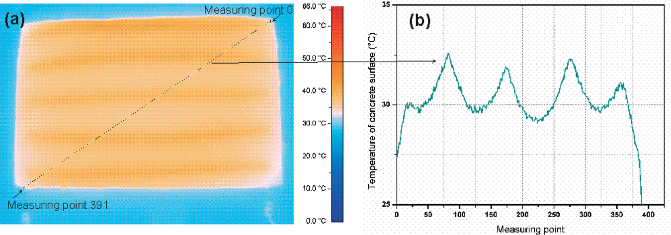
Due to the experience gained from the small specimen, the large slab is manufactured with 12 mm thickness in order to keep the heating energy at a minimum, yet to guarantee stability. The main aim of this experiment was to find the comfortable temperature if one seats on the heated concrete slab. Different measurements that are done on the large concrete slab have been detailed in Table 3. Determination of the comfortable temperature is done by sitting on the concrete slab after 100 min of passing current through the hybrid yarns. Figure 9 shows the surface temperature of concrete measured indoors and outdoors. With 25 V, it is possible to reach the comfortable temperature (which is around 29°C at room temperature). On the other hand, about 22.9°C is achieved using 30 V outdoor and it is found comfortable for that atmosphere. The concrete temperature at lower outdoor temperature is low due to the higher energy loss by convection or radiation, as explained in equation (6). From the experiment, it is found that the comfortable temperature of concrete surface when one seats on the slab is not same for indoors and outdoors. The concrete surface heated to about 22°C feels comfortable outdoors (air temperature, 14°C) compared with that heated to 29°C indoors (air temperature, 21.5°C). Although the feeling of comfort is a subjective matter, which varies from person to person, it could be assumed from our experimental results that at cold temperature of around 0–5°C, the concrete surface temperature heated to around 15–20°C would give a feeling of comfort. However, more investigations are required to make a precise statement about the energy consumption and comfort temperature depending on different climatic situations and place of application. Figure 10(a) shows the thermographic image of the concrete slab measured indoors using 25 V. The line profile of temperature shown in Figure 10(b) depicts the temperature distribution along the line in Figure 10(a).
Average surface temperature of the large concrete slab measured (a) indoors and (b) outdoors. (Heating, current on, and subsequent cooling, current off, of cement specimen. The current is turned off at the time corresponding to the start of the temperature drop). (a) Thermographic image of large concrete slab heated indoors (1.4 amp/28 V) and (b) temperature along the line. Description of tests done on large concrete slab.


Overview and conclusion
This article reports the fundamental investigations on the manufacturing of textile-reinforced heatable concrete slabs with an integrated hybrid yarn. It is usually thought that a solid ground is required to place a yarn on it using TFP technology. However, the results show that hybrid yarns can be integrated successfully into the open non-crimp carbon fabric structure by tailored hybrid yarn placement. The hybrid yarn consisting of conductive CFY as the core manufactured on a DREF-2000 spinning machine can be used as the heating element to heat the concrete slab. The advantage of using such yarn is its flexibility to be placed in a complex geometry to ensure pointwise heating. Moreover, it is also possible to customise the heating properties by using other CFYs available. From the investigations, it is found that the level of comfort is different for different atmospheres. The concrete surface heated to about 22°C feels comfortable outdoors (air temperature 14°C) compared with that heated to 29°C indoors (air temperature 21.5°C).
In order to increase the heating efficiency, a porous cement mixture of higher heat conductivity could be used. For the application of a new cement mixture, further investigations are required. Another developmental possibility could be the use of phase change material to conserve the energy.
Footnotes
Acknowledgement
The authors would like to thank Mr Thomas Bähr for his support during the testing.
Funding
This article presents a portion of the results from the research programs of the German Research Foundation (DFG) via the Collaborative Research Center (SFB 639, TP A2) for the development of the hybrid yarn at the Technische Universität Dresden. This project is also financed as part of a SAB SEED-scholarship by the European Social Fund for the development of functional concrete furniture. The authors are grateful for the above mentioned financial supports.