
Abstract
Purpose:
The primary aim of this study was to assess the 3-dimensional flare geometry of the Gore Viabahn VBX balloon-expandable covered stent (BECS) after fenestrated endovascular aortic repair (FEVAR) and to determine and visualize BECS-associated complications.
Methods:
This multicenter retrospective study included patients who underwent FEVAR between 2018 and 2022 in 3 vascular centers participating in the VBX Expand Registry. Patients with at least one visceral artery treated with the VBX and with availability of 2 post-FEVAR computed tomography angiography (CTA) scans (follow-up [FU] 1: 0–6 months; FU2: 9–24 months) were included. The flare geometry of the VBX, including flare-to-fenestration distance, flare-to-fenestration diameter ratio, flare angle, and apposition with the target artery were assessed using a vascular workstation and dedicated CTA applied software.
Results:
In total, 90 VBX BECS were analyzed in 43 FEVAR patients. The median CTA FU for FU1 and FU2 was 35 days (interquartile range [IQR], 29–51 days) and 14 months (IQR, 13–15 months), respectively. The mean flare-to-fenestration distance was 5.6±2.0 mm on FU1 and remained unchanged at 5.7±2.0 mm on FU2 (p=.417). The flare-to-fenestration diameter ratio was 1.19±0.17 on FU1 and remained unchanged at 1.21±0.19 (p=.206). The mean apposition length was 18.6±5.3 mm on FU1 and remained 18.6±5.3 mm (p=.550). The flare angle was 31°±15° on FU1 and changed to 33°±16° (p=.009). On FU1, the BECS-associated complication rate was 1%, and the BECS-associated reintervention rate was 0%. On FU2, the BECS-associated complication rate was 3%, and the BECS-associated reintervention rate was 1%.
Conclusions:
The flare geometry of the VBX bridging stent did not change significantly during 14 months follow-up in this study. Three-dimensional geometric analysis of the flare may contribute to identify the origin of endoleaks and occlusions, but this should be confirmed in a larger study including enough patients and BECS to compare complicated and uncomplicated cases.
Clinical Impact
The three-dimensional flare geometry of the Gore Viabahn VBX BECS was assessed on the first and second postoperative CTA scans, and geometrical changes during this period were identified. For BECS that were diagnosed with a type 3c endoleak or occlusion, the BECS geometry was analyzed to detect geometrical components that were related to the complication. Geometric analysis of the flare may help to better detect and identify the cause of such complications.
Keywords
Introduction
Fenestrated endovascular aortic repair (FEVAR) is considered a safe and effective treatment for pararenal aneurysms, with high technical success, low intraoperative target vessel occlusion (0.6%), and acceptable perioperative mortality (4%).1,2 Balloon-expandable covered stents (BECSs) are accommodated in the fenestrations of the target vessels by flaring the proximal end for a secure connection to the fenestrated stent graft. Sufficient flare is essential to provide a durable seal between the BECS and the fenestration, and thus prevent BECS-related complications. 3 However, BECS and target vessel complications, including type IIIc and IIId endoleaks and obstructions are still limitations of FEVAR. 4 During 3 to 5 years after the index surgery, complications have been reported in 11% to 44% of cases. Reinterventions are related to occlusion of target vessels in 5% to 15% and to BECS-associated endoleaks in 4% to 10%.2,5–8
Identifying the origin of BECS-related complications after FEVAR can be difficult. Previous research based on BECS geometry in FEVAR showed that computed tomography angiography (CTA)-derived geometric imaging of BECS is a more precise method for assessment of complications during follow-up (FU).3,9 A refined BECS-associated complication classification by van der Riet et al, 9 in which causes for obstruction, endoleak, and BECS fracture are categorized, may help to understand and predict modes of BECS failure. 9
The Gore Viabahn VBX is a relatively new type of bridging stent used in FEVAR to connect the target arteries to the fenestrated stent graft. According to preliminary studies, the VBX BECS is reported to be safe and effective to be used in fenestrated custom-made endografts.10–16 However, the geometry of the flared end of the VBX is currently unexplored.
This study had 2 aims: first, to assess the VBX flare geometry and apposition with the target artery on the 1-year post-FEVAR CTA scan and compare it with the first postoperative CTA scan; and second, to investigate BECS-associated modes of failure regarding stenosis, occlusion, and endoleak.
Materials and Methods
Study Design
This study incorporated retrospective clinical data of patients from 3 centers participating in the VBX Expand Registry, which is a postmarket safety and performance study of the GORE VIABAHN VBX Balloon-Expandable Endoprosthesis.
Inclusion criteria were patients who underwent FEVAR and who had both the procedure and FU between January 2018 and December 2022. Other inclusion criteria were (1) at least 1 visceral artery treated with the VBX as BECS, (2) 2 postoperative CTA scans available, 1 between 0 and 6 months (follow-up 1 [FU1]), and 1 between 9 and 24 months (follow-up 2 [FU2]). Exclusion criteria were treatment with a combined fenestrated and branched endograft configuration, VBX not primarily used as the bridging stent (eg, in case of relining or reintervention), and when the CTA scan was not suitable for analysis (insufficient contrast [generally below 300 HU], wrong field of view, or the absence of axial images and slice thickness <3.0 mm).
The Medical Ethical Institutional Review Board granted dispensation for Medical Research Involving Human Subjects Act (WMO) obligation (registration no. MERC 2022/00076). Local approval was obtained at each of the 3 hospitals. Patient data were processed and electronically stored in agreement with the Declaration of Helsinki—ethical principles for medical research involving human subjects. Data were extracted from the electronic patient files and were processed and analyzed anonymously.
Data Collection
Study data were collected and managed using Research Electronic Data Capture (REDCap, version 8.10.18; Vanderbilt University, Nashville, TN, USA). Clinical data were extracted from (electronic) patient records to REDCap. The database consisted of information from the preoperative CTA scan assessment for target vessel anatomy, preoperative diameter measured at the level of the orifice of the target artery, and patient records, including CTA FU imaging details for FEVAR-related complications, which were classified based on classification for complications after FEVAR by Oderich et al. 4
Technical success was defined as successful deployment of the planned fenestrated stent graft and BECS(s) with patent target vessel(s) and absence of type 1 or 3 endoleaks on completion angiography. 17 Causes of endoleak (E1-E4) and obstruction (O1-O4) were geometrically assessed using a BECS-related complications classification as reported by van der Riet et al. 9
CTA Scan Protocol
In all 3 centers, the arterial phase of the preoperative and postoperative CTA scans were analyzed. The postoperative CTA scans were imported to 3mensio (Pie Medical, Bilthoven, the Netherlands). The CTA scans were obtained on a 384-slice CT scanner in all centers (Somatom Siemens Healthinees, Erlangen, Germany). The imaging protocol from the first center included 100 mL (4 mL/s) of diluted contrast (Iomeron 350; Imaging GmbH, Konstanz, Germany) administered intravenously. Images were reconstructed to 0.75-mm slice thickness using a medium-smooth convolution kernel. The imaging protocol of the second center included 110 mL (3.5 mL/s) of diluted contrast (Ultravist 370; Bayer Pharmaceuticals, Germany) administered intravenously. Images were reconstructed to 1.0-mm slice thickness using a smooth convolution kernel. The third center imaging protocol included 100 mL (4.0 mL/s) of diluted contrast (Iomeron 400; Bracco Imaging, Italy) administered intravenously. Images were reconstructed to 0.6-mm slice thickness using a smooth convolution kernel.
Flare Geometry Analysis of BECS
Postprocedure FU CTA scans were analyzed in a 3mensio vascular workstation. Measurements were performed according to a predefined measurement protocol as previously used by van der Riet et al. 9
A manual center line was defined through the center of the main body in the aorta. Thereafter, branching center lines of the VBX, including the target vessels, were determined semiautomatically with the 3mensio fenestration tool. Center lumen points of the center lines were manually corrected and double checked by a second observer. Thereafter, 12 Cartesian coordinate markers were placed to define the BECS geometry. Four markers were placed at the distal end (D1-D4) of the BECS, 4 at the level of the fenestration (F1-F4), and 4 proximally at the flared end (P1-P4) (Figure 1A and B).
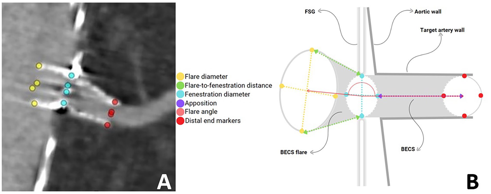
A: Schematic presentation of Cartesian coordinate markers placement of BECS flare geometry in 3mensio. The markers at the level of the flare (P1-P4) were placed at the proximal end of the BECS, markers were placed at the level of the fenestration (F1-F4), and markers were placed at the distal end of the BECS in the lumen of the target artery (D1-D4). B: Schematic presentation of the BECS flare geometry. The geometric image of the 3-dimensional flare is defined by flare diameter (D-flare), flare-to-fenestration distance (FFD), fenestration diameter (D-fenestration), the flare angle and apposition. The flare-to-fenestration diameter ratio (D-ratio) is calculated by the median flare diameter divided by the median fenestration diameter.
Apposition between the BECS and the target artery, defined as the centerline distance from circumferential apposition between the BECS and the target artery to the distal end of the circumferential apposistion of the BECS. 17
The center lines and marker coordinates from 3mensio were imported into dedicated flare geometry assessment software, created with MATLAB (MathWorks, Natick, MA, USA). The software was described and validated in a previous study. 19 Figure 1B displays the dimensions of the BECS geometry that were calculated with the software:
The mean diameter of the BECS at the flared end (D-flare).
The mean diameter of the BECS at the level of the fenestration (D-fenestration).
The minimal, maximal, and mean distance between the flared end of the BECS and the fenestration of the main body over the circumference of the BECS (flare-to-fenestration distance; FFD).
The angle between the center of the flared end of the BECS, the center of the fenestration, and the center of the distal end of the BECS (flare angle).
The flare-to-fenestration diameter ratio (D-ratio), describing the amount of flaring of the BECS relative to the diameter at the fenestration, was calculated from D-flare and D-fenestration. A ratio of <1 means that the diameter of the flared end of the BECS is smaller than the diameter of the BECS at the level of the fenestration, and a ratio of >1 means that the diameter of the flare is greater than the diameter of the fenestration.
Statistical Analysis and Data Export
Data are presented as means with standard deviation for continuous variables or median with interquartile range (IQR) in case of skewed data, and number and percentage for categorical variables. Distribution of the data was appraised by visual evaluation of histograms and quantile-quantile plots and the skewness-kurtosis test. Potential statistical differences were tested with the paired-sample t test. A p value of <.05 was considered significant. Statistical analysis was performed in SPSS 28 software (IBM Corp, Armonk, NY, USA).
Results
Patient Characteristics
This study comprised 43 patients (mean age 73±8 years, 88% men) with a total of 153 fenestrations (5-FEVAR, n=1; 4-FEVAR, n=27; 3-FEVAR, n=12; 2-FEVAR, n=1; and 1-FEVAR, n=2), of which 90 fenestrations were primarily treated with a VBX. Indication for FEVAR was a pararenal aneurysm (n=37), a thoracoabdominal aortic aneurysm (n=4), or a previous dissection with aneurysmal dilation (n=2). Thoracoabdominal aortic aneurysms were treated with thoracic endovascular aortic repair and FEVAR in a single intervention or as staged procedures. The preoperative median aneurysm diameter was 58 (IQR: 55–63) mm. At FU2, the median aneurysm diameter was 53 mm (IQR: 46–61 mm). The aneurysm diameter remained stable in 21 patients, decreased >5 mm in 21 patients and increased >5 mm in 1 patient. No endoleak was observed in the patient with aneurysm growth.
A custom-made Zenith fenestrated stent graft (Cook Medical Europe, Inc.) was used in all cases (median diameter, 34 mm; IQR, 32-36 mm), with one scallop in 42%. The preoperative dimensions of the 90 arteries that were treated with a VBX were as follows: left renal artery (LRA; n=29) 5.4±1.2 mm, right renal artery (RRA; n=27) 5.6±0.7 mm, superior mesenteric artery (SMA; n=15) 8.1±1.2 mm, and celiac trunk (CTR; n=19) 7.8±1.3 mm. The balloons used for flaring were 8×20 mm (n=11), 10×20 mm (n=59), and 12×20 (n=20). The VBX sizes used were 7×29 mm (n=29), 6×29 mm (n=18), 8×29 mm (n=11), 7×39 mm (n=10), 8×39 mm (n=5), 6×19 mm (n=4), 9×39 mm (n=4), 6×39 mm (n=3), 5×29 mm (n=2), 8×19 mm (n=1), 9×29 mm (n=1), 8×59 mm (n=1), and 5×15 mm (n=1).
Fenestrated endovascular aortic repair procedural technical success was 93%. Technical failure in 3 patients (7%) was caused by unsuccessful stenting of the CTR, 2 cases due to misalignment of the VBX and the fenestrated stent graft with the target artery and 1 due to a sharp angulation of the CTR relative to the aortic center lumen line. The fenestrations in these 3 patients were left open due to long seal zone. The median CTA FU time was 35 (IQR: 29–51) days on FU1 and 14 (IQR: 13–15) months on FU2. The 30-day mortality rate was 0%.
VBX BECS 3-Dimensional Flare Geometry
Flare geometry on FU1 and FU2 is reported in Table 1. The median FFD was between 4.5±2.0 and 6.8±2.2 mm and FFD did not change significantly during 14 months of FU. The mean diameter of the D-flare was 8.5±1.4 on FU1 and 8.5±1.4 on FU2. The mean diameter of the D-fenestration was 7.2±1.1 mm on FU1 and 7.1±1.1 mm on FU2. The flare-to-fenestration D-ratio was 1.19±0.17 and did not change during FU. Three BECS (3%) on FU1 and 7 BECS (8%) on FU2 had a D-ratio of <1. The mean apposition length was 18.6±5.3 mm and also did not change during FU. The mean flare angle was 31°±15° on FU1 and changed significantly to 33°±16° on FU2 (p=.009).
Geometrical Variables of the VBX BECS Flare.
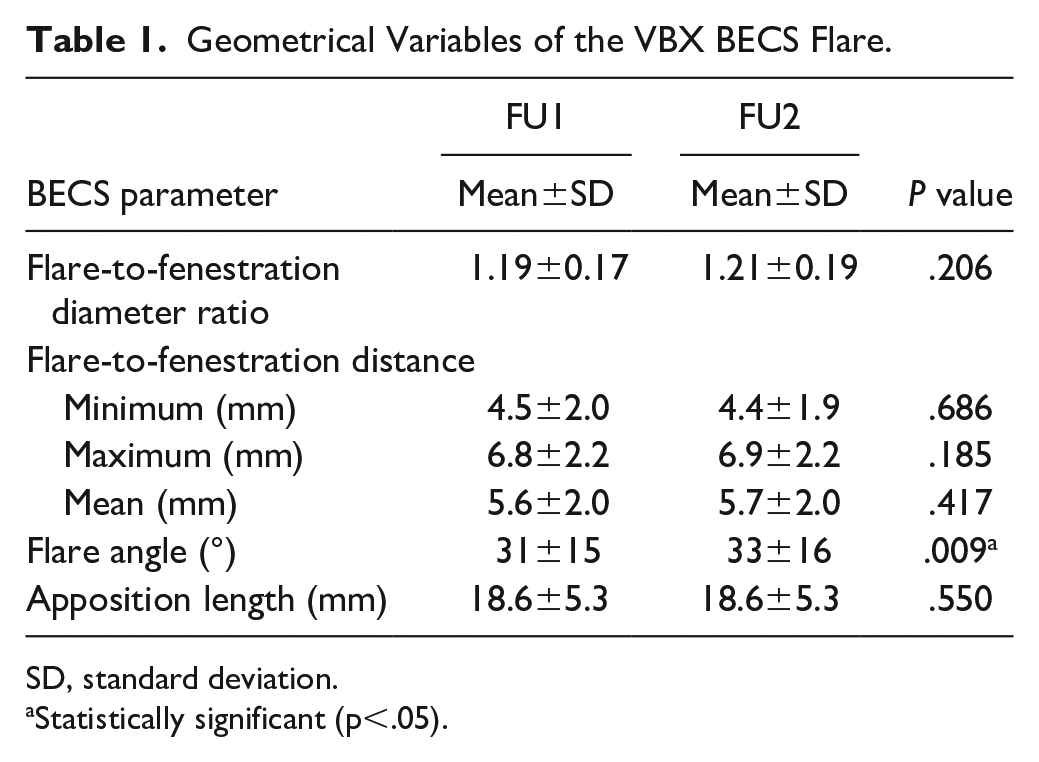
SD, standard deviation.
Statistically significant (p<.05).
Case Example of a Noncomplicated BECS
An example displayed in Figure 2 shows the geometric analysis of a VBX placed in the LRA with a BECS geometry close to the average values reported for the study population in Table 1. Follow-up 1 was at 20 days and FU2 was at 17 months. The VBX D-ratio, FFD, and apposition remained constant, and the flare angle changed 17°.
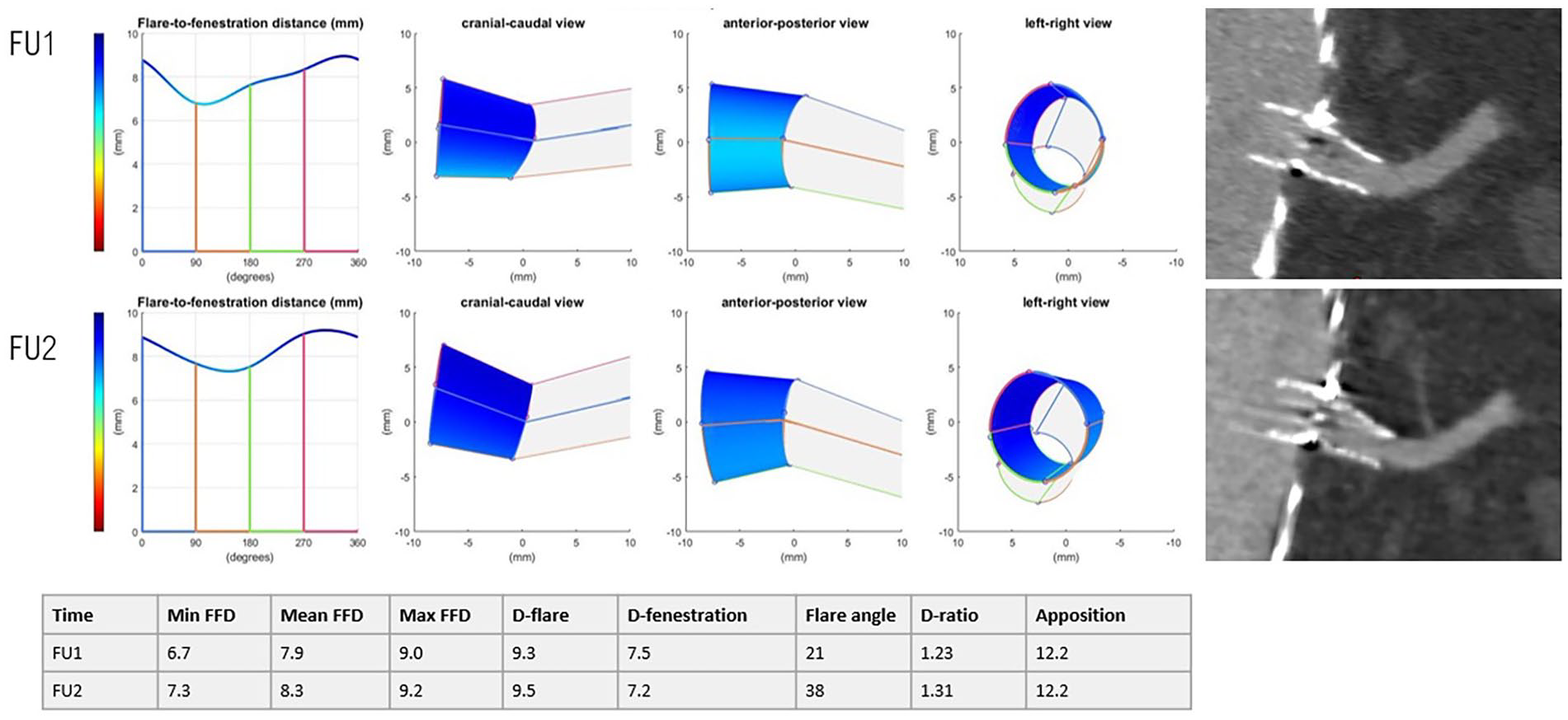
Representation of the 3-dimensional flare geometry (cranial-caudal, anterior-posterior, and left-right view) and 3mensio snake view of a VBX in the left renal artery, without complications.
BECS Complications
An uncomplicated course was observed in 87 BECS (97%). Balloon-expandable covered stent-related complications were reported in 3 VBX stents (2 left renal arteries and 1 celiac trunk) during a median FU of 14 (IQR: 13–15) months. There were no BECS complications related to main body migration. In none of the 3 complicated BECS, neither severe calcification/stenosis was determined on the pre-EVAR CTA nor misalignment was detected of the fenestrations to the target arteries.
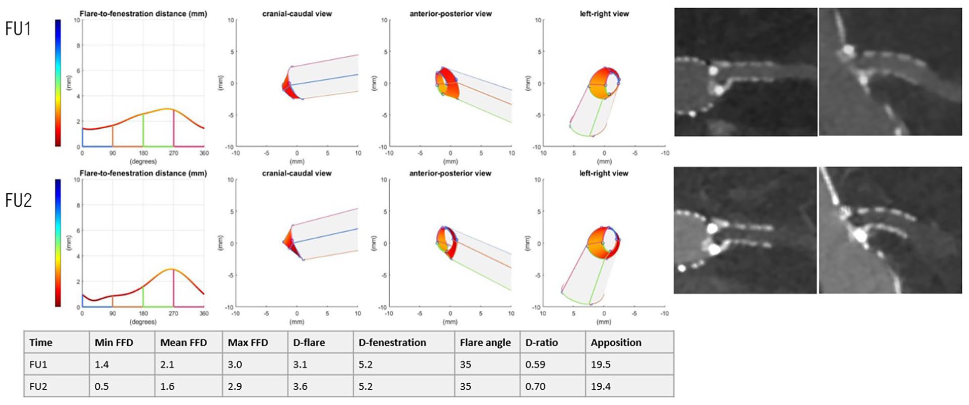
One VBX in the LRA showed a type 3c endoleak after 14 months (FU2), which was classified as E1 (insufficient flare) using Van der Riet’s classification (Figure 3). 9 On the first postoperative CTA scan, the FFD was already insufficient (0.2 mm). Through a common femoral artery access the LRA was cannulated after which a VBX stent graft was deployed and flared. This relining was performed 15 months after the index procedure. At 5 years FU, the BECS remained patent.
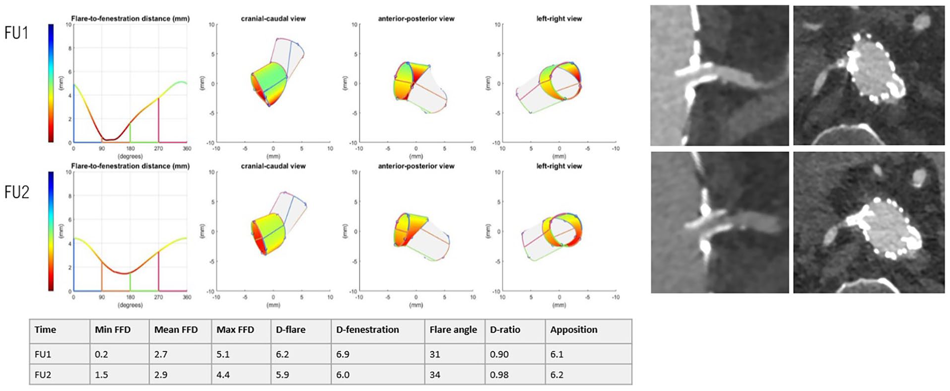
Representation of the 3-dimensional flare geometry (cranial-caudal, anterior-posterior and left-right view) and CTA scan shown in the snake view of 3mensio of an LRA with a type 3c endoleak.
Two VBX stents occluded. One occluded VBX in the CTR, reported after 36 days on FU1, was classified as O1, O3, or O4 (flare compression/misalignment with the target artery and/or nongeometric cause) (Figure 4). The complication was asymptomatic, so no reintervention was performed. Three-dimensional geometry showed a low D-ratio of 0.86 and a long FFD of maximal 18.1 mm. Also, the distal outflow may have been obstructed due to severe curvature of the native vessel. The patient had no history of coagulation disorder, and there was no plausible cause from medication use, but the exact cause of the occlusion could not be verified and may have been multifactorial.
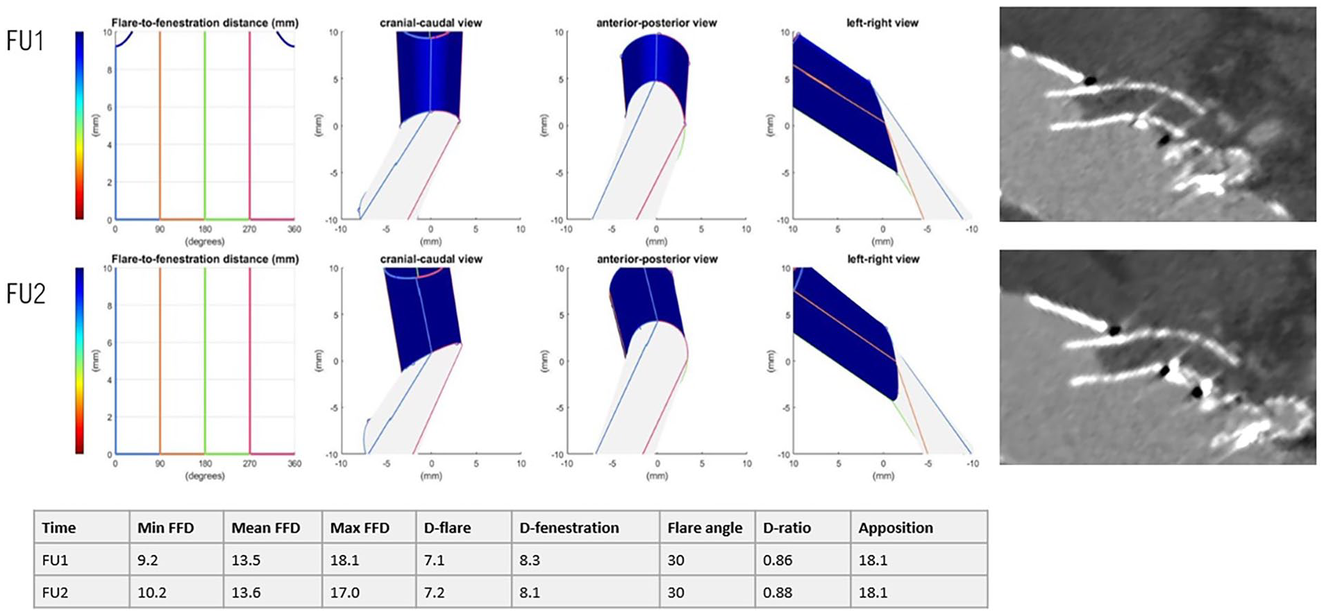
Representation of the 3-dimensional flare geometry (cranial-caudal, anterior-posterior, and left-right view) and CTA scan shown in the snake view of 3mensio of a CTR occlusion.
Another occlusion in the LRA was reported after 14 months (FU2) and classified as O1 and F2 (fractured and compressed flare) (Figure 5). The stent fracture with a D-ratio of 0.59 was in retrospect already visible on FU1. There was no planned reintervention because of old age, so consequently, there was atrophy of the left kidney, but a functional right kidney remained. Furthermore, the 3-dimensional geometry showed a short minimal FFD of 0.5 mm on FU2, but this had not yet led to a type 3c endoleak.
Representation of the 3-dimensional flare geometry (cranial-caudal, anterior-posterior, and left-right view) and CTA scan shown in the snake view of 3mensio of the LRA with a crushed flare.
Discussion
This study showed that 93% of the VBX BECS used had an uneventful FU with stable flare geometry and apposition with the target artery. Short-term data from published studies show similar results, with 92% to 100% freedom from complications.10–12,14 Furthermore, this study showed that most of the 3-dimensional flare geometry of the VBX did not change significantly during 1-year of FU. A small but significant change was found for the flare angle that may be the result from continued adaptation to target vessel anatomy. Another study showed that the preoperative angle of the target vessel changes postoperatively, a process that may continue during short-term FU. 20
The 3 VBX BECS with complications were classified according to the previously proposed classification system for post-FEVAR BECS-associated complications based on the BECS geometry. 9 Although the aim of this study was not to compare flare geometry of the 3 complicated BECS with noncomplicated BECS, deviations from normal geometry were clearly observed for the 3 complicated BECS. One patient experienced a type 3c endoleak that was most likely caused by a short FFD. Another patient with a BECS occlusion had a very long FFD, which could be a risk factor for in-stent occlusion. In the third patient, a crushed flare was retrospectively detected on the first postoperative CTA scan with the help of geometric analysis, whereas the actual occlusion was observed only on the 1-year FU CT, and consequently, the kidney could no longer be saved. Hence, assessment of flare geometry may assist in detecting failure at an early stage and may contribute to detecting the cause of a complication.3,9 Owing to the low number of uncomplicated cases in this study, we could not perform a statistical analysis, nor other specific correlation regarding BECS-associated modes of failure.
The VBX is a relatively flexible and conformable stent, so it could be susceptible to angular changes due to main body migration or hemodynamic forces.11,12 Clinical implications of change in the angle were not observed in this study and may be the subject of future studies with longer FU and a larger number of patients. Tran et al have described the features of hostile target vessel anatomy, which depends on the take-off angle, end-stent angle, and curvature. 21 There is the suggestion that the VBX is more able to adapt to target vessel anatomy, but we could not demonstrate that in this study because the geometry of the target vessels was not assessed on the preoperative CT scans, and no comparison was made with other bridging stents. As a consequence, whether the VBX is a (more) suitable stent for challenging anatomies due to its conformability could not be determined from this study. This may be a subject for further research.
An adequate D-ratio, sufficient circumferential length of the flared part (FFD) of the BECS, and sufficient apposition with the target artery are assumed essential to provide long-term stent patency. In this study, the D-ratio was 1.19±0.17 at 1 month, which is similar to observations of Overeem et al, 18 who measured a mean D-ratio of 1.14±0.19 for the BeGrafts (Bentley Innomed, Hechingen, Germany) and Advanta V12. 18 Squizzato et al measured a slightly larger mean D-ratio of 1.27±0.27 for the VBX and measured a D-ratio of 1.13±0.26 for other types of stents. According to Squizzato et al, 3 the VBX had better flaring features compared with other BECS, and the VBX had a significantly higher flare ratio (p=.011). 3 This corresponds to observations of Torsello et al, 12 who tested the biomechanical characteristics of the VBX and concluded that the VBX had good flaring properties. 12
In this study, the D-ratio was similar to findings in other studies with other stents. How the D-ratio is affected by balloon size and the flaring protocol is unclear, but this may play an important role. Also, whether a higher D-ratio is associated with better clinical outcomes is not yet clear, and besides that, it may be advantageous in increasing the seal to the fenestrated stent graft. It has been hypothesized that the conformable design of the VBX, with independent stent rings and low metal content, may be susceptible to crushing. 22 Future research should study the effect of type 3c endoleak and stent crushing on the D-ratio.
Advantages of detailed visualization of BECS geometry post-FEVAR include a helpful tool to the endovascular specialist to have a quality check on the different parts of each BECS which is difficult to determine on conventional post-FEVAR CTAs. The described method can be used for all types of BECS and is not exclusively for the VBX stent graft. Drawback of the method is the fact that it is not DUS applicable, but a CTA is needed.
One of the limitations of this study was that only the 1-month and 1-year CT scans were assessed. Complications that were not observed during this period and may have become evident during later FU may have been missed. Also, stent fractures without clinical consequences are hard to detect and may have been missed during radiologic review. By inclusion of only a few participating centers a selection bias could have been introduced. In addition, due to the fact that patients who did not undergo one of the CTA’s were excluded from the study another selection bias could have been introduced.
A second limitation was that the geometric analysis was based on manually placed marker points and was therefore prone to some degree of measurement error. The accuracy has previously been estimated at a mean difference with repeatability coefficient (RC) of 0.8 (2.1) mm and 0.4 (1.0) mm, mean (RC) interobserver measurement variability at 0.7 (2.6) mm and 0.1 (0.7) mm and the interclass correlation coefficient was 0.77 and 0.92, for the FFD, and diameters, respectively. 19
A third limitation is that the software is not approved by the Conformité Européene or the U.S. Food and Drug Administration and is therefore not qualified to use in a clinical setting.
Finally, the small number of 90 VBX BECS, the lack of a control group, and the limited number of complicated VBX BECS are limitations of this study. Therefore, statistical comparison of complicated BECS geometry with noncomplicated BECS geometry was not possible. Consequently, no thresholds for high-risk geometric conditions could be established. Also, it is not possible to investigate long-term patency and geometric changes, considering the short FU period and limited quantity of current VBX data. Measurement variability or a type I error may have contributed to the small, but significant change of angle that was found in this study. In future studies should verify this finding.
Conclusion
The flare geometry of the VBX bridging stent did not change significantly during 14 months FU in this study. Three-dimensional geometric analysis of the flare may contribute to identify the origin of endoleaks and occlusions, but this should be confirmed in a larger study including enough patients and BECS to compare complicated and uncomplicated cases.
Footnotes
Acknowledgements
Everyone who contributed to this manuscript is listed as an author.
Author Contributions
Concept and Design: FF, JV, RS; Data collection: FF, BS, IT, MP, DE, AF, CZ; Writing the Manuscript: FF, BS, IT, JV, CZ, RS; Critical Revision: all.
Declaration of Conflicting Interests
The author(s) declared the following potential conflicts of interest with respect to the research, authorship, and/or publication of this article: CZ has consulting, research support, honoraria, and travel support from: W.L. Gore & Associates.
Funding
The author(s) disclosed receipt of the following financial support for the research, authorship, and/or publication of this article: An unrestricted research grant was provided by W.L. Gore & Associates for this study.
Ethical Statement
The Medical Ethical Institutional Review Board granted dispensation for Medical Research Involving Human Subjects Act (WMO) obligation (registration no. MERC 2022/00076). Local approval was obtained at each of the 3 hospitals. Patient data were processed and electronically stored in agreement with the Declaration of Helsinki—ethical principles for medical research involving human subjects. Data were extracted from the electronic patient files and were processed and analyzed anonymously.