
Abstract
Established cost-effective remediation solutions for unstable masonry wall systems exist. However, non-invasive procedures do not exist for detecting the extent of stability loss due to corrosion of wall ties within mortar joints, thus identifying which walls are prone to imminent collapse. A working method for estimating remaining stability and resilience of aging brick veneer and cavity brick masonry walls is proposed. Grounded by in-situ field inspection and condition assessments for various aged brick veneer and cavity brick walls, the proposed non-destructive in-situ assessment method and associated numerical structural analysis model have been validated and calibrated against detailed experimental corrosion science testing of metal wall ties. While still restricted to ground walls or where access can be safely gained by either scaffolding or abseiling, the proposed method can qualitatively detect vulnerability of masonry veneer and cavity brick wall collapse.
Introduction
Throughout the world, masonry veneer and cavity brick wall stability relies on metal fitments (wall ties) cast into the mortar bedding joints of external brick walls. Traditionally, wall ties are galvanised steel, but since the late 1990s stainless-steel wall ties are often the choice for resisting corrosion in more aggressive exposure conditions. 1 The wall ties allow the stabilised internal masonry leaf or framing structure to support the outer brick leaf against horizontal forces, for example wind and earthquake actions.
There is a stock of buildings in Australia and indeed throughout the world that contain a hidden danger. This danger includes corrosion of concealed metal wall ties, weakened mortar and inherent design defects, that can cause bricks, or entire brick wall panels, to dislodge and fall under much lower loads than predicted by design standards, such as moderate winds.2–4 With several relatively recent wall collapses attributing causality to corrosion often of significant socio-economic impact,5–7 and even death, 8 the danger of collapse for external masonry walls due to deterioration of concealed wall ties is considered of high importance.
Masonry panel stability should and can be designed to meet modern construction standards and their associated service life expectations.1,9,10 Such standards have carefully considered durability requirements and construction techniques. Alas, the reality is that many buildings approaching or exceeding their design life will have concealed deteriorated wall ties and reduced capacity to resist brick dislodgement.2,11 Cost-effective solutions for timely remediation exist, 12 however current invasive mortar-embedded corroded wall tie location methods are onerous. 13 So, the challenge remains: to cost-effectively and timely determine which walls, or sections of walls, have suffered sufficient loss of stability and are prone to sudden collapse.
A cost-effective method is proposed herein for timely inspection of large metropolitan areas based on ongoing research led by The University of Newcastle Critical Infrastructure Performance and Reliability Group and supported by the Western Australia Government Department of Local Government Industry Regulation and Safety, Curtin University, Structural Health Monitoring Consultancy EngAnalysis and key asset stakeholders under the financial support of the Australian Research Council.
Non-destructive vibration-based method for loss of masonry wall stability
The main premise of the method is that physical properties, such as mass and stiffness of a structure, are affected when damage incurs. The damage, be it by corrosion or other concealed construction errors, in turn causes a change in natural frequency, vibration mode shape and damping ratios. 14 A novel and reasonable modelling idealisation is then achieved by adapting established modal parameter-based mechanics15–17 to stiff masonry wall panel structures.2,14
Various techniques exist for obtaining modal data. Laser Doppler vibrometery 18 or microwave radar interferometry 19 are techniques currently being trialled for their unique advantage of being able to achieve data at range. Alas, an impact hammer,14,20 paired with two strategically selected affixed accelerometers, was the technique selected due to its convenience and portability. Albeit limited to surfaces where the operator must make direct contact with, an impact hammer does provide a higher signal-to-noise ratio compared to other forms of ambient vibration. 21 Moreover, a high signal-to-noise ratio provides the benefit of the data being less influenced by noise, such as other potential forms of vibration. This is important when considering its application in real-world conditions where masonry wall facades will be subject to traffic and other forms of ambient vibration during inspection.
Once the modal data was obtained via an impact hammer method, the effort of translating the damage index for structural analysis was successful. This was achieved by completing a comprehensively bespoke systematic statistical characterisation of corroded wall tie brick and mortar-embedded couplet mechanical testing. With considerations made for mortar type, wall tie material type as well as amounts of corrosion both in compression and in tension,22,23 a reference state model was then achieved from the modal analysis. The model was then calibrated via the systematic corroded wall tie material characterisation and finally validated against a comprehensive corrosion field testing of cavity environmental data. 24
The field testing of masonry wall cavity wall tie corrosion24,25 has so far confirmed that variability exists between the air cavity micro-environment and the internal and external environments of brick veneer and cavity brick house modules. Furthermore, if left unprotected the steel wall ties will show measurable section losses even after 12 months of exposure, with greater corrosion losses observed if located in more shaded elevations, potentially being worse for masonry brick veneer systems where cavity annual temperature fluctuations were measured to be higher on average compared to cavity brick.
The aforementioned efforts culminated in a corrosion-based stochastic material model were then used to optimise Young's moduli of corroding stability wall tie with time. The optimised Young's moduli can then be translated into a suitably real-world validated stiffness loss parameter, which now can be used in a complex non-linear finite-element structural analysis of brick veneer and cavity brick wall panels. Such structural analysis can be used for design of new masonry brick veneer and cavity brick wall panels, or indeed remediation planning endeavours of existing masonry wall panels.
Required equipment and application details
This section details the equipment utilised in an example application of the working prototype non-destructive method for replication in practice. For this example, a PCB Piezotronics large sledge impact hammer with the model number 086D50 was used in the test. As shown in Figure 1, impacts are to be applied in the out-of-plane direction of the wall. While high skill level of impact hammer expertise is not necessary, care must be taken to ensure consistent impact direction and locations. Additional considerations must be given on selecting the appropriate force level to not damage the wall being inspected. Taking into account of the equipment requirements of selected data acquisition systems and the frequency range of interest. If the user would value a higher reliability of readings, then a structural eigenvalue analysis or prior information of the test subject may inform the required impact intensity, and the suitability of the test setup can be gauged by the data quality.
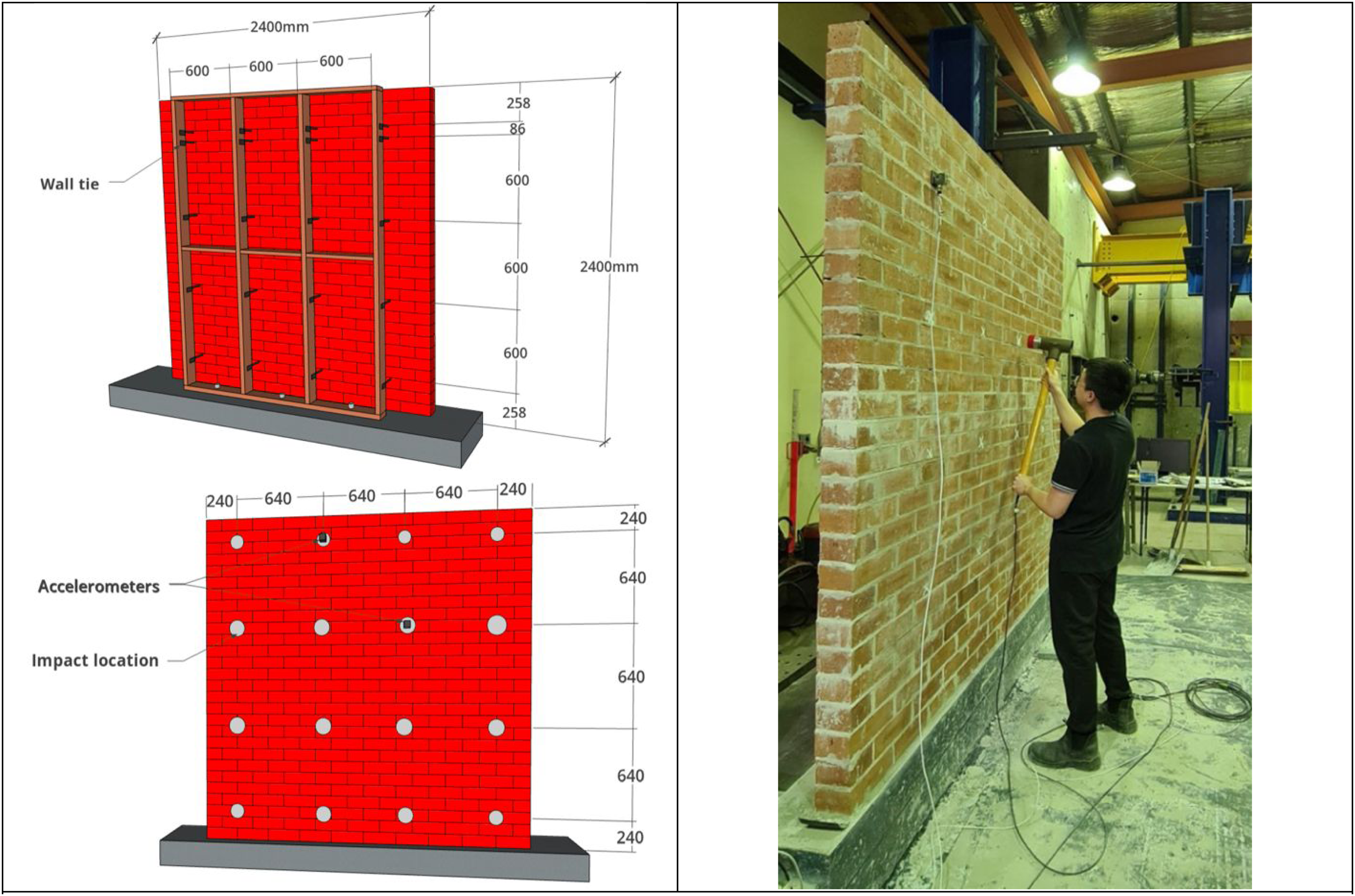
Schematic location of wall tie, impact and accelerometer locations (left), and process of out-of-plane impact hammer testing (right). 14
Based on standardised wall tie construction spacing location standards, as well as the previously completed comprehensive modal analysis, 14 a 4 × 4 impact grid was deemed sufficient for a typical 2.4 m wide by 2.4 m tall masonry panel. Impact locations can be close, but not necessarily exact, to actual wall tie location. There is no need for extra impact statistical treatment. Instead, careful impact, regardless of location, was exercised until a suitable measurement was achieved. In practice, this meant for a trained operator, approximately 1–2 hits per data acquisition repetition. Care should be taken to avoid panel edges and avoid unintentional damage.
The method was also optimised so that only 2× relatively inexpensive accelerometers are required for capturing the impact vibration data. 14 In this example, approximately 25 mm wide, 65 mm tall and 40 mm deep HS-173 accelerometers with 100 mV g−1 sensitivity, a frequency range of 2 Hz to 10 kHz and a dynamic range equal to ±80 g were used. Accelerometer attachment is also inexpensive via commonly available adhesive options (e.g. double-sided tape, or warm glue gun with small smooth metal plates). As illustrated in Figure 1, for best results it is recommended that the accelerometers are placed at locations where we expect large vibration responses as a rule of thumb. It is also recommended to avoid node points (i.e. points that do not vibrate at certain natural frequency), while ensuring good coverage of the whole wall.
Any generic or commercially available software and data logging system and output software can be used. In this example, National Instruments cDAQ-9178 data logger and simple LabVIEW built user interface were used to capture and display the readings. In this example, a sampling rate of 1000 Hz and a pre-trigger of 20 ms were sufficient to capture the complete signal of the impact, which in this case being between 700 and 900 N. As exemplified in Figure 2, each impact was recorded until the vibrating motion decayed back to its natural state. Importantly, considering real-world vibration noise level interference conditions of walls being inspected while the building is utilised (e.g. pedestrian and vehicular traffic), filtering and signal processing techniques should be used to mitigate noise and improve the signal-to-noise ratio. Various techniques exist, 26 however in this example, a fifth-order Butterworth low-pass filter with a cutoff frequency of 350 Hz was applied to the raw measurement signals, attenuating noise at higher frequencies, followed by application of additional exponential window functions for more accurate frequency response and thus modal parameter estimation. 14 Due to an inherent limitation of the impact hammer itself when applied to critical modes for general structures, including masonry veneer structure. Higher frequencies would require a denser measurement and impact location array for complex mode shapes where pertinent, which in turn would take away the method's practicality. Hence, the decision was made to limit the measured frequency to 350 Hz since only the first few modes of masonry excitation are of interest; there was no need to go beyond 350 Hz since this would not affect the method’s accuracy. The force and acceleration data was cleaned and then Fourier-transformed to the frequency domain for further processing, where the built-in MATLAB least square rational function (LSRF) algorithm was used with the specific commands ‘modalsd’ and ‘modalfit’ to ultimately obtain the results of the natural frequencies and their corresponding mode shapes. The stabilisation diagram resulted from the described algorithmic steps is shown in Figure 2, indicating peaks that correspond to the natural frequencies. 14 Finally, damage or loss of stability can be qualitatively measured by quantifying the change in modal frequencies between data sets taken between different time periods; for example, between 1 year and 2 years of service, or indeed yearly after reaching end of design service life.
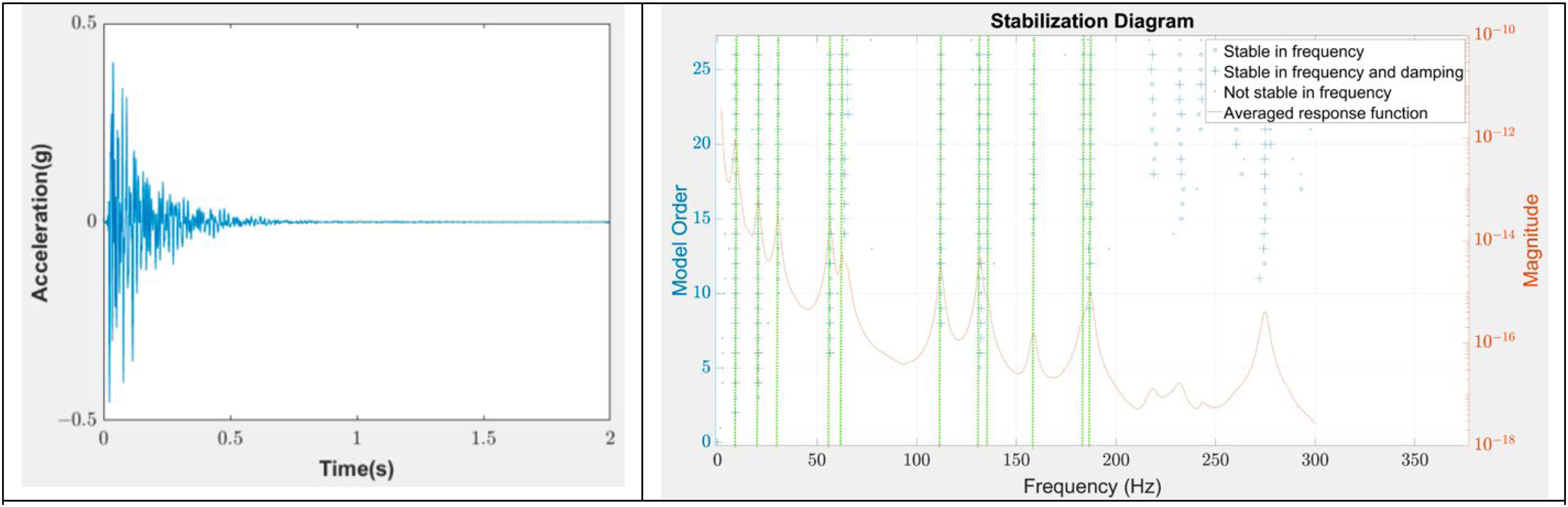
Example data captured by the accelerometer (left). Example stabilisation diagram generated using the LSRF algorithm for the captured accelerometer data (right). Green dotted lines represent the estimated natural frequencies after cross-checking with the finite-element model. 14 LSRF: least square rational function.
Prototype results and discussion
Figure 3 shows an example output result of the method. In this prototype example, it was possible to have access and manually detach and reattach the metal ties of the tested walls. The results show that the predicted damage locations, based on natural frequency change and the absolute differences in mode shape displacements, align with the manually removed ties, where higher ΔΦ value (shown in yellow) matches locations of actual wall tie failure or disconnection.
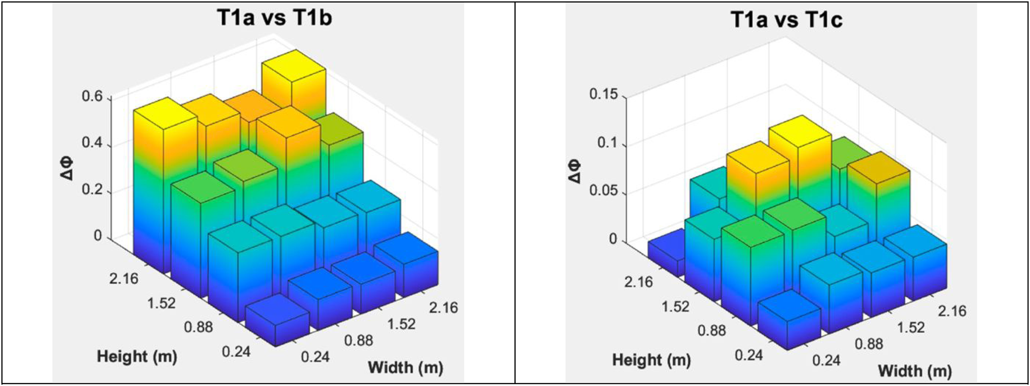
Example of non-destructive damage localisation method results. In this example, two wall tie full deterioration/disconnect cases are shown: (left) top two rows of wall ties compromised; (right) two middle rows of wall ties compromised. Higher ΔΦ indicate locations of actual wall tie failure or disconnection.
In practice, various unknown factors such as replacement bricks, remediation works and mortar repair are expected to influence accuracy of results. Moreover, errors in mode shape curvature forward and backward difference approximation, environmental noises are also expected to affect accuracy. In other words, after data is collected, the peak of the damage index may not be at the exact actual tie location, but rather one column or row away. A combination of formulations and/or algorithms was considered but based on detailed analysis 14 this was deemed not recommended as different vibration-based methods are unable to be normalised to the same scale, resulting in inconsistent results.
Refinements to the method are continuously being made to eliminate the potential for misleading results during application. For example, if the method is applied on existing buildings, then lack of prior knowledge on the undamaged state will also likely lead to erroneous results. It is proposed that short interval periodic inspections are performed on critical assets as to for a reliable reference state for observing changes in modal frequencies. Alternatively, a robust long-term structural health monitoring system that can capture information on significant structural movements could also increase accuracy of model outputs. Field prototyping and validation of the method under real-world conditions are underway.
Regarding influence of corrosion, wall tie failure due to corrosion damage has been shown to prevail over traditional timbre connection tension pullout failure or wall tie compression buckling only when there's at least 40 and 39% section loss, respectively.22,23 Thus, at its present state, the model is unable to provide quantitative estimation of individual wall tie corrosion losses. Ultimately, however, from a regulatory perspective, knowledge of wall instability is, after all, sufficient to action remediation. This endorses the application of the proposed method and the following conclusions.
Conclusions
The proposed method can non-destructively detect vulnerability of masonry veneer and cavity brick wall collapse due to corrosion of stability wall ties.
The method can also numerically provide qualitative and quantitative estimation of remaining wall stability, which in turn can be used for timely remediation strategies or further numerical structural analysis
Application of the contact method is still restricted to ground walls or where access can be safely gained by either scaffolding of abseiling.
The method is still unable to provide quantitative estimation of individual wall tie corrosion section losses.
Footnotes
Author contributions
Conceptualisation: I.C. and M.M.; methodology: I.C., M.M., L.T., C.L. and A.H.; validation: I.C. and M.M.; investigation: I.C. and M.M.; resources: I.C.; original draft preparation: I.C.; review and editing: I.C., M. M, C.L., L.T., A.H. and P.daC.; visualisation: I.C., L.T. and C.L.; project administration: I.C., M.M. and P.daC.
Funding
The authors disclosed receipt of the following financial support for the research, authorship and/or publication of this article: The authors would like to acknowledge the pivotal financial support from the Australian Research Council and the Western Australia Government Department of Local Government Industry Regulation and Safety via Linkage Project LP220100028. The authors also would like to take this opportunity to appreciate all the in-kind contributions from the various industry partners who have formally committed their involvement for the duration of the project.
Declaration of conflicting interests
The authors declared no potential conflicts of interest with respect to the research, authorship and/or publication of this article.