
Abstract
Reinforced concrete is an option for pontoons for offshore wind and other energy-related facilities. It has the potential for lower maintenance in situ and ease of construction but despite its long successful applications history, concern persists about the risk of reinforcement corrosion. Recent investigations have concluded that chloride-induced corrosion is unlikely, short-term or long-term, for well-made, well-compacted and low permeability concretes. This experience is briefly reviewed. Initiation of corrosion occurs as pitting corrosion, irrespective of chloride concentration, and for reinforced concrete only within wet air-voids in the concrete at the steel–concrete interface. Experimental evidence shows that in parallel to this, a gradual loss of concrete alkalis to the external environment occurs, thereby eventually lowering the pH of the porewater solution sufficient for general corrosion of the steel to become thermodynamically feasible, irrespective of chloride concentration. A model for the development of corrosion loss as a function of period of exposure and of concrete permeability is described. It is concluded that reinforcement corrosion in marine environments is not a significant risk for high-quality, well-compacted, low permeability concretes made with non-reactive aggregates. This has direct implications for the construction and inspection of new reinforced concrete structures in seawater and ocean waters.
Introduction
The trend towards offshore wind and other energy facilities has raised the potential for reinforced concrete structures to play a role,1–4 one that for the offshore oil and gas industry largely has been taken by steel ‘FPSOs’ (floating production, storage and offloading) platforms. Floating platforms (‘floaters’) typically are either specially constructed or converted from oil tankers. They are tethered in place using multiple mooring lines extending from a turret on the flatform (often at the bow, but also mid-ships) to the ocean floor. 5 ‘Floaters’ have the advantage over fixed platforms such as those in shallower waters (e.g. the North Sea) of being able to be used in deep as well as shallower waters and the possibility, with some advanced dis-connection arrangements for risers and other umbilicals, to be moved to avoid extreme weather or to be relocated to other oil and/or gas fields in other geographical locations. Preliminary concepts for reinforced concrete ‘floaters’ have them as thin-walled boxes, essentially closed at the top and of triangular, square plan or circular plan form, with or without outstands or extra buoyancy tanks.3,4 In terms of long-term durability, for reinforced concrete floaters resistance to the possibility of corrosion of the reinforcement steel is a key issue. Some information about this can be ascertained from observations of the durability of structural forms in parallel ocean or seawater environments. These forms include reinforced concrete ship hulls, barges and caissons. These are broadly similar to the floaters being considered for energy platforms that typically have relatively thin walls. Experiences with other reinforced concrete structures, such as reinforced concrete bridge piles in marine environments including in immersion zone, ‘tidal’ or wave zone, splash zone and marine atmospheric zones may be relevant, provided the concrete cover to the reinforcement bars is not excessive. In all cases, long-term durability (e.g. over decades) is of interest.
The next section provides a brief overview of long-term corrosion observations of reinforced concrete structures. This is followed by a review of relatively recent results and observations from a long-term experimental program that used model reinforced concrete specimens, mostly made with seawater and in one set made with additional sodium chloride. The results over several years of exposure showed a distinct difference between corrosion initiation and the onset of long-term reinforcement corrosion. They also showed the effect of concrete permeability on the rate of progression of long-term corrosion and, for corrosion initiation to occur, the necessity of air-voids (of whatever size or shape) in the concrete at the steel–concrete interface. Air-voids have long been suspected as important for initiation and subsequent corrosion, but the corrosion processes involved have only recently been clarified. The role of chlorides and the validity of the term ‘chloride-induced’ corrosion are discussed with reference to the thermodynamics involved. Attention is then turned to the principal mechanism that governs long-term corrosion of reinforcement, especially for reinforcement encased in poorer-quality, more permeable concretes. It involves the (slow) dissolution of calcium hydroxide from the concrete and its diffusion (leaching-out) to the external environment, rate-controlled by the permeability of the concrete and concrete cover thickness. It is noted that classical research has shown that the rate of dissolution of calcium hydroxide increases proportionally with the concentration of chloride in the concrete pore water. These mechanisms then permit further refinement of the model previously proposed for the development of corrosion loss with time. Supporting evidence is presented. Comments are made about the practical implications and inspection of existing marine-reinforced concrete structures.
Reinforcement corrosion in experiments and some field observations
The notion that corrosion of steel reinforcement in concrete can occur within a few years of first exposure in seawater or related marine exposures is based, in part, on experimental results reported in 1959 by Shalon and Raphael. 6 These results and others at the time led to Code requirements in some jurisdictions limiting the permitted concrete chloride concentration, ostensibly to reduce the risk of reinforcement corrosion, based on the then current notion that chlorides ‘attack’ the passive film supplied by the concrete alkalis. 7 However, an attempt to replicate those experimental results failed to reveal any significant reinforcement corrosion within the short time originally reported. Instead, it took many years for there to be any reinforcement corrosion and that which did occur occurred mainly in relatively open, high aggregate-cement ratio concretes. 8 Those results were obtained in an extensive experiment, on-going, and commenced in 2004 (noted in the sequel as the ‘2004 experimental program’). It used the same-sized specimens (40 × 40 × 160 mm) and a centrally steel bar (6 mm diam.) similar to the Shalon and Raphael 6 experiments. It is much more comprehensive than the Shalon and Raphael experiments in that it comprises some 56 sets of different concrete mixes, each of 20 identical specimens cast at the same time. It covers a range of water-cement ratios (0.5, 0.65, 0.8, 0.95) and aggregate-cement ratios (2, 4, 6) combinations. 8 Most specimen sets were made with local Pacific Ocean seawater as mixing water and used local blended cement and aggregates and sand from the same sources throughout. One set (20 specimens) was made with low-heat cement and another with local soft fresh (tap-)water. One set had a 50% increase in salinity. The steel bars were ‘as delivered’ but free from grease and mill-scale. Observations of the interior state of the concrete and the steel bar for all specimens were made at yearly intervals during the first few years of exposure. For these, corrosion largely was absent but eventually evidence of corrosion was observed for some of the specimens, mainly only for relatively open, high aggregate-cement ratio concretes. 8 Concretes made with limestone as aggregate as well as those made with fresh water as mixing water showed relative fewer instances of lesser corrosion, even after 12 years exposure. At the time of writing (2025), there is very little external evidence of reinforcement corrosion for any of the concrete specimens remaining in the fog-room.
The results for the 2004 experimental program appeared difficult to explain in the light of the Shalon and Raphael 6 experiences but eventually this was clarified through a re-examination of their experimental procedure as reported. This indicated poor (or no) compaction of their model concretes. In contrast, the specimens in the 2004 experimental program were all compacted using the laboratory shaking table under consistent conditions and under expert technical supervision. 8 As will become clear, compaction of the concrete is a major factor both in short-term and long-term corrosion of steel reinforcement.
There are very few other laboratory-based experiments for reinforcement corrosion. One is an experiment conducted over 28 years for 36 3-metre long reinforced concrete beams 280 mm × 150 mm cross-section with 10 mm cover and exposed to wet artificial chloride atmospheres. 9 The beams showed vertical cracks due to bending under the applied vertical load. This loading and the crack width, and thus the likely crack depth, is greater than normally permitted by design codes for concrete structures. 10 Forensic examinations showed early corrosion losses of the steel reinforcement irregularly along the steel bars. Whether this was associated with the distribution of deep cracking is an open question.9,11 A significant reduction in the overall rate of corrosion occurred after some 4–5 years. This was attributed to a build-up of rust products and calcium carbonate. 11 Corrosion occurred mainly along the bottom of the bars (cf. the later laboratory experiments reported by Melchers and Chaves). 8 However, after a decade or more, the rate of corrosion was observed to have increased markedly. That corrosion was still highly variable along the reinforcement bars and sufficient to cause concrete cracking and spalling, despite the corrosion being categorised by the investigators as ‘mild’. 12
In terms of experiences of reinforcement corrosion in field exposures, there is a long history of observations and some forensic investigations for reinforced concrete structures in coastal and ocean conditions. These largely support the experimental findings reviewed above. For example, Friedland, 13 Wakeman et al. 14 and Beaton et al. 15 observed little or negligible evidence of reinforcement corrosion over decades-long exposure periods in seawater conditions. Other more recent cases with similar findings have been summarised.16–20 For example, Figure 1 shows an example of reinforcement within a piece of reinforced concrete slab extracted from an exposed wharf deck after some 70 years exposure as a harbourside loading wharf. The observation of little or no corrosion of the steel in sound concrete in marine atmosphere conditions is similar to that for other examples. 20
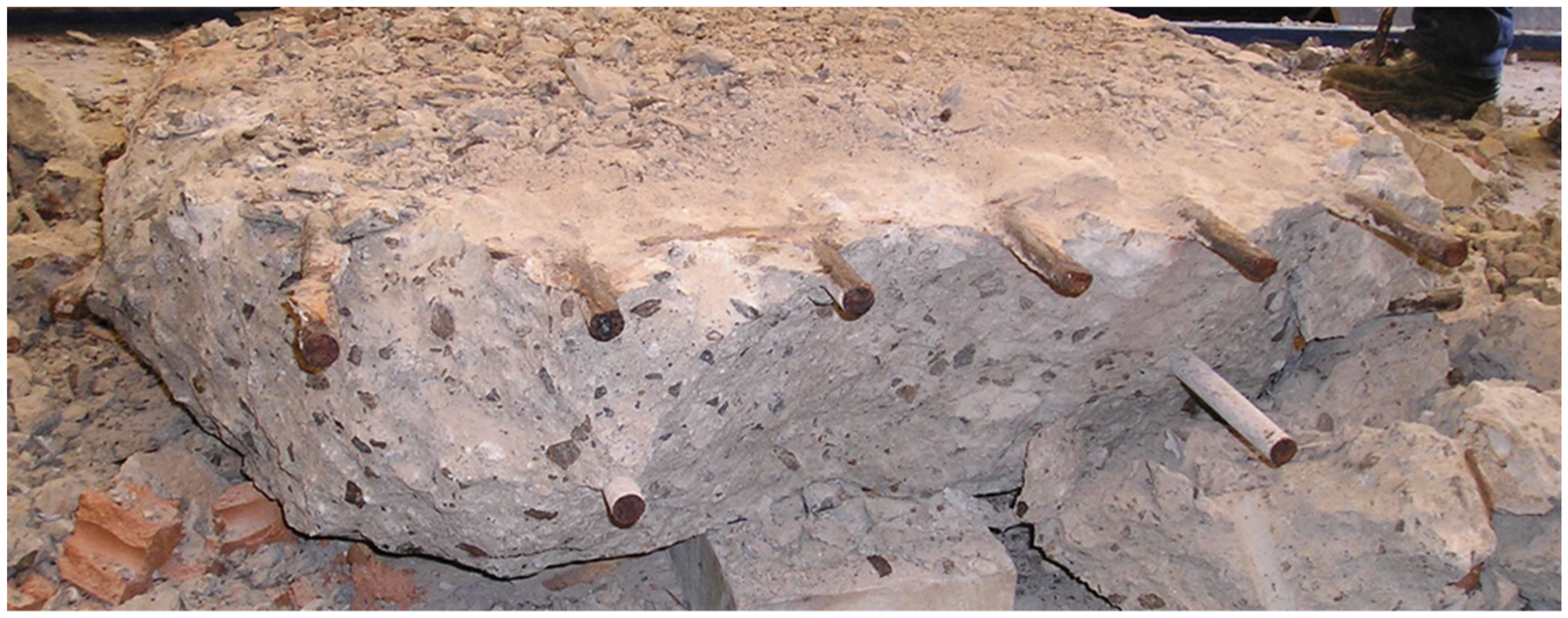
Example of reinforcement bars (25 mm) in a concrete slab after about 70 years exposure to harbourside marine atmosphere conditions (Newcastle, Australia harbour), showing negligible (upper bars) and no (lower bars) corrosion of the steel.
For thin-walled reinforced concrete structures, a major example demonstrating long-term durability is the suite of Phoenix caissons built during 1943–4 and placed in the North Sea off the Normandy (F) coast. Some 200 reinforced concrete caissons were constructed in a period of about 6 months, mostly in the Thames area and the southern part of England, in what has been described as one of the world's major construction projects. 21 Immediately after construction and launching they were stored under water off the coast of England, awaiting refloating and deployment just after the D-day landings. They were towed by a flotilla of mainly British and American tugboats, across the English Channel to the Normandy coast, France. There they were placed on the seafloor to become the major parts of a breakwater system intended to protect two artificial harbours (Mulberry A and B). The caissons were major structures, of various sizes up to 61 m long, 10 m wide, 18 m high, exterior wall thickness 340 mm–600 mm, divided into compartments with vertical walls and originally open-topped. Intended for just 3 months of deployment, they were of very simple design to aid speed of construction and the use of the available labour. Several different consultants were employed to design and supervise the construction, using whatever aggregates and steel were available local to the (12 different) construction sites. A nominal similar concrete mix was used for all caissons. 22 No records appear to be available regarding the techniques used for concrete compaction. Although designed to be resistant to expected wave forces, no consideration was given to long-term durability. 22 Soon after the caissons were placed in position an unexpectedly large major storm event caused many of the caissons to be overtopped with seawater, flooding the compartments and causing them to burst. 23 Owing to extensive damage, Mulberry A was abandoned. The somewhat lesser damage to the caissons of Mulberry B is still evident in photos and videos on multiple websites. These also show that, more than 80 years later, remarkably little visual evidence of reinforcement corrosion. Independent evidence for this became available in 2015.
A forensic investigation in 2015 by a French engineering consultant reported, as expected, very high-chloride concentrations at the steel reinforcement bars (2.6–5.9% wt cement). 24 Concrete cores taken through the caisson walls revealed little or no corrosion of any of the reinforcing bars, irrespective of immersion, tidal or atmospheric splash zone exposure. At the time of the investigation, this was after some 70 years of continuous exposure. Drone aerial images at that time also show little visible damage from reinforcement corrosion. In some cases, yield-line folds in the concrete elements as caused by storm damage reveal reinforcement bars but with little obvious corrosion of the bars themselves. 25 For the few caissons that have ‘broken their backs’, presumably as a result of eventual foundation failure, the exposed reinforcing bars also showed only moderate corrosion. 25 However, there are some isolated locations with evidence of more serious corrosion.
Some of the caissons show rust stains at the horizontal ‘cold joints’ between concrete casts. Examination of the construction drawings showed that at these joints the (vertical) reinforcement is continuous through the joint. This geometry shows that a pathway existed for the entry of seawater into the cold joint and thus for the (long-term) loss of concrete alkalis, thereby lowering, after long exposures, the pH of the concrete including at the steel reinforcement. In turn this permitted highly localised corrosion under low pH and low oxygen conditions, resulting in the production of ferrous chloride. 26 Because ferrous chloride is highly soluble in water, it can readily leach out of the joints in seawater conditions. When it reaches an aerated exterior environment ferrous chloride will oxidise to FeOOH type insoluble rusts, leaving the watery-looking rust stains visible on the exterior concrete adjacent to the cold joints. There are other examples that show that even relatively minor localised rust staining can be the result of serious but very localised corrosion.10,26
Similar warning signs of highly localised corrosion were observed by the author on the inside of one of the reinforced concrete panels forming the hull of a reinforced concrete barge (Figure 2). This barge was one of six inspected in 2009 after 40 years (est.) continuous operation for naval ammunition transport in Sydney Harbour. The rusts shown in Figure 2 occurred at cracks right through the concrete hull panel, just above the waterline when the vessel is fully loaded. No visual evidence of rust stains or concrete cracking was observed anywhere else on the barges. No information appears to be available regarding concrete mix design or workmanship matters. Similar observed were made by the author for a number of reinforced concrete barges beached along the banks of the Severn Estuary at Purton, UK, where they are still subject to tidal seawater exposure. These barges date from WW2 were in continuous use for many years in the Bristol region as grain carriers but ultimately taken out of service because of a degree of moisture permeation through their concrete hulls. However, when inspected in 2008, there was very little evidence of rust staining or concrete damage from reinforcement corrosion. 27 Information about concrete mix design, etc., could not be ascertained.
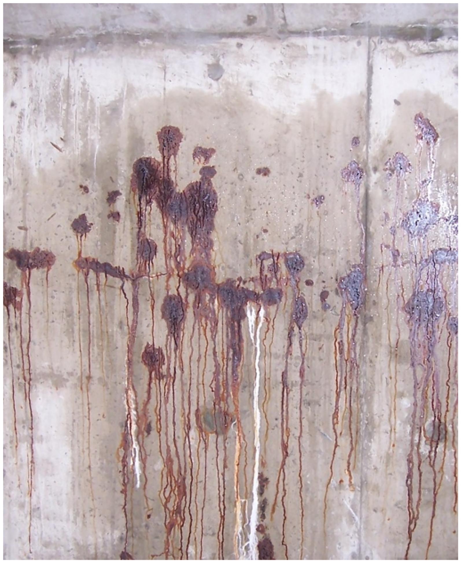
View of inside of the hull of a reinforced concrete barge after about 40 years deployment in Sydney harbour. Note the horizontal cracking and the pattern of watery-looking rust stains.
Observations for the corrosion of reinforcement in concrete members such as piles or beams in marine exposures also may be relevant, more so when the concrete cover can be considered equivalent to that for ship hulls. In both cases, the physical shape of the structure itself is irrelevant. In this context, the corrosion behaviour of steel reinforcement for more than 800 reinforced concrete piles, each cast horizontally onshore and driven partway into ocean beach sands to form the substructure of a 1930s road-bridge is of interest. 20 When inspected in 2011 after some 80 years of continued exposure to immersion, tidal, splash and atmospheric marine conditions, there was almost no evidence of reinforcement corrosion or corrosion damage. The only significant corrosion that was detected was highly localised, at a crack deep enough to extend through the 62.5 mm concrete cover and past two steel 32 mm (diam.) reinforcement bars on one side of the one pile. There, both steel bars had completely corroded away at the crack, leaving conical ends to the bar remaining inside the concrete on both sides of the crack. The corrosion mechanism has been described as similar to that responsible for the rust staining shown in Figure 2.28,29
Feasibility of marine corrosion of steel in concrete
The precursor to long-term corrosion of steel in concrete is corrosion initiation. That process and also the process of propagation of corrosion must be considered in terms of the laws of chemical thermodynamics. This is irrespective of the overall physical conditions – only the chemistry of the environment immediately around the steel and the properties of the steel itself are relevant. This extends to steel wholly or partly in concrete. In corrosion theory, thermodynamic feasibility usually is referenced to the relevant Pourbaix diagram. This is more convenient than applying the Gibbs free energy criterion for the relevant chemical reactions. Pourbaix diagrams have the added imprimatur that they are based on extensive experiments directly involving the metal and environment of interest.
For the general corrosion of steel in waters of various chloride concentrations, it is conventional to apply the Pourbaix diagram for iron. 30 Figure 3 shows that diagram for two extreme conditions: (a) low concentration of chlorides (10−3M) (light grey region, centre top) and (b) high-chloride concentration typical of seawater (0.6 M) (darker grey region at top right). Added to Figure 3 are the regions in which pitting corrosion is feasible, and (at right) the region of passivity and the region of ‘imperfect passivity’. The latter denotes that any pre-existing pitting permits further pitting. The passive region denotes that corrosion products render corrosion not feasible almost as soon as it commences. 31 On Figure 3, the potential ESHE = −0.44 V is that corresponding to the electrochemical potential for iron, while the ‘grey balloon’ denotes the same potential at pH 13, the latter taken as corresponding to the pH of concrete prior to the loss of any alkalis. The grey circled ‘balloon’ is used to indicate that there is a degree of uncertainty about both the pH level and the potential ESHE = −0.44 V. This does not affect the overall analysis given here.
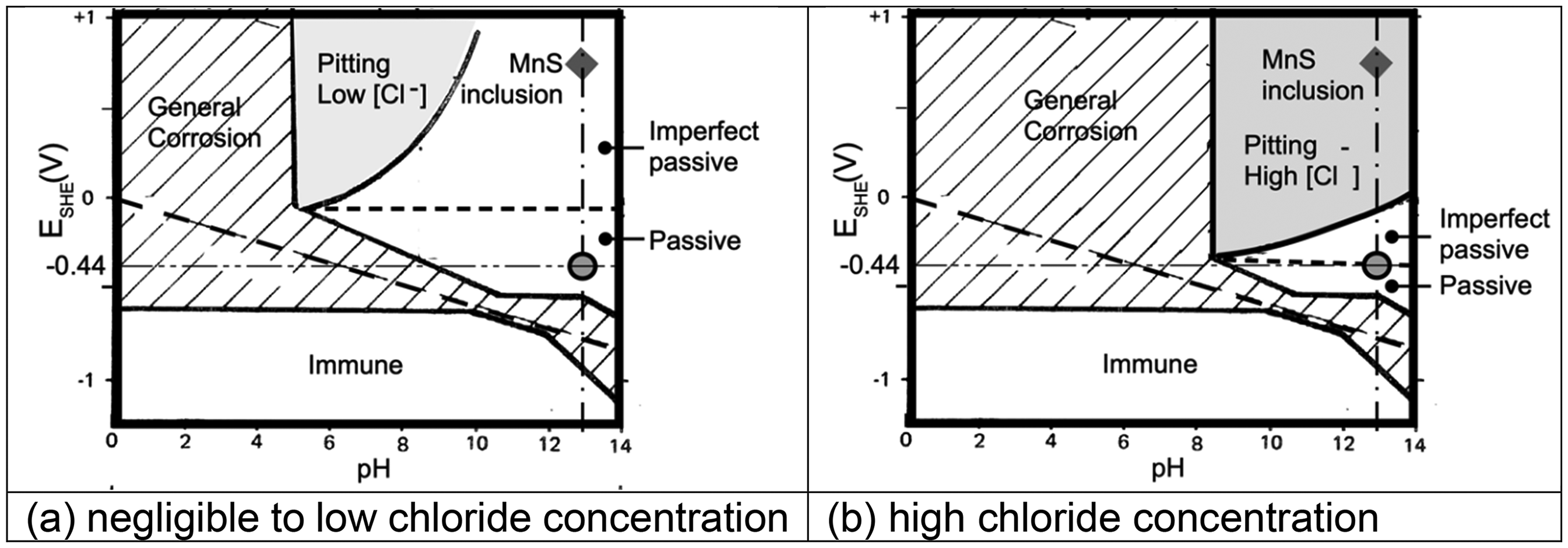
Potential (ESHE) - pH diagram (Pourbaix diagram) for iron in seawater showing region in which pitting is feasible, and the grey circled (‘balloon’) region, representing the conditions at the steel–concrete interface at an air-void in the concrete. The diamond indicates the likely E-pH conditions of the MnS inclusion at initiation (see text). The boundaries are shown as clear dividers between regions – in practice a small degree of uncertainty is associated with them. 30 However, this does not affect the above analysis. (a) Negligible to low-chloride concentration. (b) High-chloride concentration.
In Figure 3(a), the (light grey) region for which pitting corrosion is feasible moves to the right and slightly downwards with increasing chloride concentration, shown as the darker grey region in Figure 3(b). This trending movement also applies to the imperfect passivity region while the passive region shrinks. It is evident that irrespective of such changes with increased chloride concentration, the grey balloon for E-pH of iron does not enter any region feasible for corrosion of iron, whether pitting or general corrosion. This remains the case for pH lower than 13 and thus also in pure water (typically pH around 7). Yet pitting has been observed to occur almost immediately on first exposure, including in unchlorinated fresh water 32 – the crucial factor is that those observations were for steel, not iron. The difference is that steel contains non-Fe inclusions. These play a critical role in corrosion initiation, as well established. For example, in ultra-high purity iron, essentially without inclusions, corrosion is extremely low, including pitting corrosion, even in low pH environments such as hydrochloric acid and with wide differences in grain size.33,34 For steels, however, inclusions are numerous throughout, possibly with some grain orientation along the rolling direction. 35 Importantly, there is much classical evidence that localised and pitting corrosion initiates principally at MnS inclusions.36,37 Contrary to some interpretations (e.g. 38 ), there is no need for the presence of chlorides, theoretically 36 or practically. 32
The diamond-shaped symbol in Figure 3 has been added to shows the potential associated with MnS inclusions. Figure 3(a) shows that for low-chloride concentrations pitting initiation via MnS inclusions is feasible only in the region shown as ‘imperfect passive’. For high-chloride concentrations (Figure 3(b)) such pitting is feasible in the ‘pitting’ region. In both cases (and for all chloride concentrations in between), pitting via MnS inclusions continues to remain feasible as pH is reduced to circum-neutral. General corrosion becomes feasible, via the Fe component of the steel, once pH falls below about 9.
As in the original Pourbaix experiments, the above assumes the presence of water and of oxygen, the latter including that of dissolved oxygen in water. For steel in ideal, well-made concrete with intimate contact between the steel and the concrete idealised as a homogeneous medium, both are likely almost completely excluded, or be available through inward diffusion at very low rates. This indicates that corrosion is not feasible, even as pitting corrosion. However, this scenario must be compared with the situation inside practical concretes, even those of low permeability.
In practice, it is more likely that there will not be perfect interfacial contact between the steel and concrete. It has been suspected for some time that corrosion initiates mainly in air-voids at the steel–concrete interface 39 although the mechanism involved has remained in doubt. 40 On the other hand, numerous and extensive observations as part of the 2004 experimental program (see above) have revealed that the critical mechanism for the feasibility of corrosion is localised pitting and crevice corrosion of the steel and that this occurs almost exclusively within air-voids in the concrete at the steel–concrete interface. 8 A further example of this is shown in Figure 4. At left is shown the essentially uncorroded condition of the side of the steel bar that was upward facing in the concrete at the time of casting and, at right, the downward facing side of the bar. As noted earlier, the experimental studies showed that air-voids in the concrete occurred principally along the lower side of horizontal (or near-horizontal and sloping) bars. The occurrence of these voids was attributed to compaction and workability of the concrete. It also was where initiation of corrosion (as pitting and crevice corrosion was observed, with correspondence between pitting and voids shown in cross-sectional views). 8
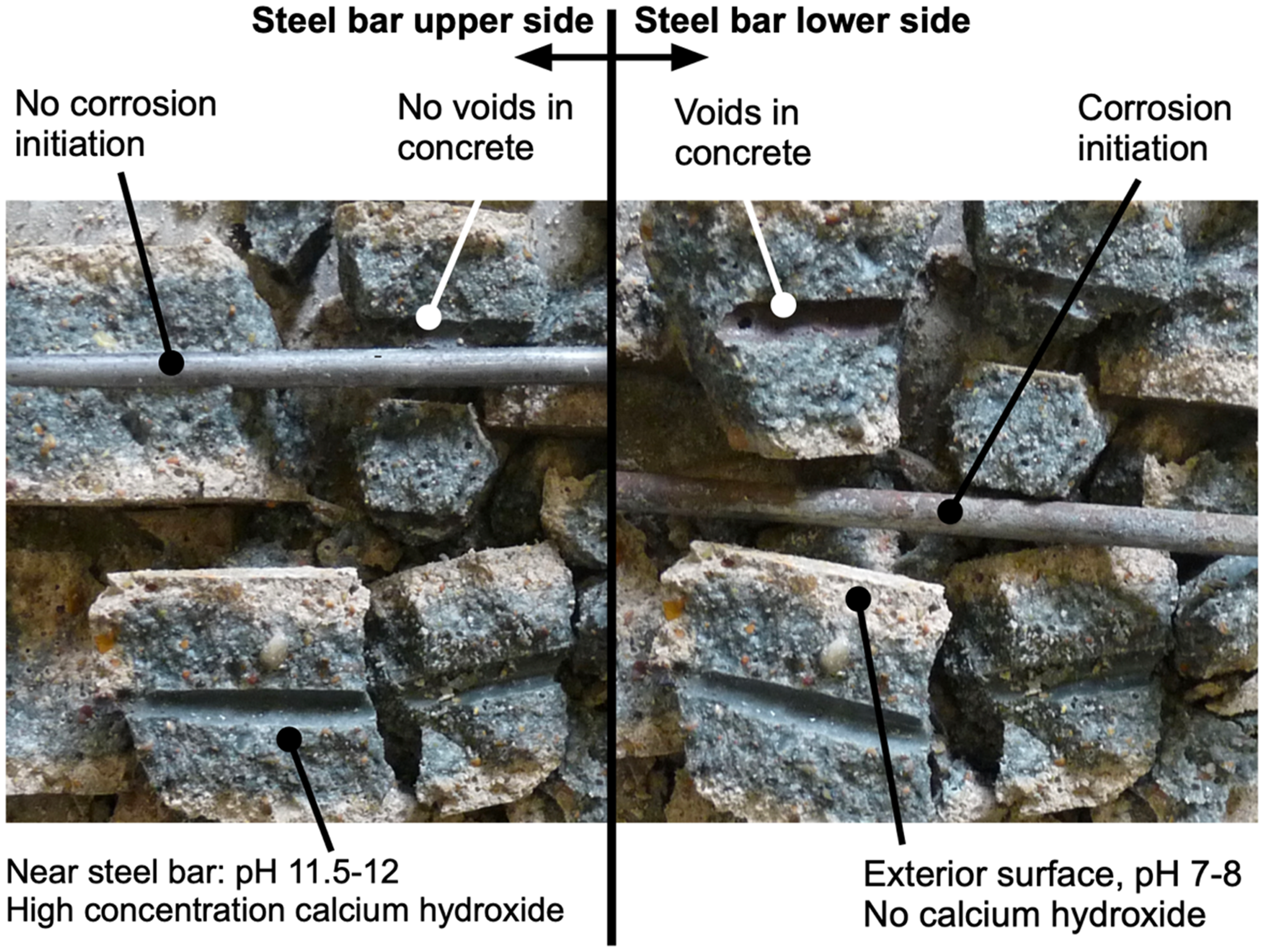
Concrete specimen 40 × 40 mm in cross-section, 160 mm long, split lengthwise along the 6 mm diam. steel bar after 12 years exposure in the laboratory fog-room, showing limited evidence of corrosion of the steel inside a well-compacted, low permeability concrete. Note the differences in concrete pH and the presence of calcium hydroxide and its loss indicated by the lighter coloured concrete along the outer surfaces of the specimen (see text). The steel bar on the right has been rotated through 180˚ about its axis (and moved) from its orientation at left.
It follows from the above that contrary to the conventional wisdom, chlorides are not an essential requirement for pitting or crevice corrosion of steel to be feasible, and that this is the case irrespective of the concrete pH. The latter is illustrated in the Pourbaix diagram (Figure 3) with the variation of chloride concentration and the corrosion potentials of Fe and of MnS inclusions. This situation changes for older concretes, with already some loss of concrete alkalis and thus loss of pH. For these, the grey E-pH ‘balloon’ for iron will have moved to the left. This shows that initiation of general corrosion and immediately subsequent corrosion of Fe becomes feasible as general corrosion once the porewater pH falls below about 9.
Loss of concrete alkalis
In addition to showing the presence of localised corrosion (pitting, crevice) of the steel opposite air-voids in the concrete at the steel–concrete interface in the first few years of exposure, 8 the 2004 experimental program also showed a change of colour of the concrete. Another example of this can be seen in Figure 4. The lighter concrete effect was observed to extend further into the concrete from the outside surfaces for longer periods of exposure. Following detailed investigations, 41 this phenomenon was eventually attributed to the slow loss of calcium hydroxide by outward diffusion and leaching. This alkali has the slowest rate of dissolution of concrete alkalis 42 and thus governs porewater pH. Its loss from the concrete governs a corresponding loss of concrete pH as also confirmed in classical experiments. 42 Once the pH at the steel becomes reduced to about pH 9 general corrosion is feasible, as noted above (cf. Figure 3). Again, the presence of general corrosion in addition to pitting was confirmed in the 2004 experimental program. 8 The specimen in Figure 4 is one example.
Once sufficient loss of calcium hydroxide has occurred at the steel–concrete interface and thus at the surface of the steel, theory indicates that general corrosion can proceed (Figure 3). This is, again, irrespective of chloride concentration, provided the solution (water) is stagnant. This is a classical result, first reported by Heyn and Bauer 43 and independently confirmed for various chloride solutions by Mercer and Lumbard. 32 Importantly, this applies to steel in concrete since the pore waters in concrete are essentially stagnant. This is not always the case in laboratory tests.
The interpretation from experimental observations such as in Figure 4 leads to the hypothesis that the rate of corrosion under the state of loss of calcium hydroxide depends in the first instance on its rate of loss from the zone around the embedded steel. In turn, this depends on the permeability of the surrounding concrete and its extent (depth of cover). The rate of loss of calcium hydroxide may depend also on the rate of its dissolution in water and on the availability of water in the concrete, noting that this rate increases somewhat with, and proportionally with, increased chloride concentration. 42 As described further below, it is the latter effect that relates to the classical notion of ‘chloride-induced’ corrosion.
Development of reinforcement corrosion in marine concretes
Turning now to the time-dependent development of corrosion of steel in concrete, it is essential that cognizance be taken of the fundamentals of steel corrosion and the thermodynamic feasibility of initiation and further corrosion, as governed by its environment. For steel encased in concrete, the initial environment is the high pH imparted by the porewater of the concrete, noting, again, that the encasement effect of the concrete may not be perfect and that this will have a direct effect on concrete permeability as well as on the presence or otherwise of air-voids in the concrete at the steel–concrete interface.
Consider first the case of a highly impermeable concrete. For this case air-voids at the steel–concrete interface can be expected to be negligible and thus, in accordance with the propositions above, initiation of corrosion and thus any subsequent corrosion is unlikely. With time a slow rate of inward-moving loss of calcium hydroxide can be expected, with associated reduction of pH, eventually (at point A in Figure 5) permitting general corrosion of the steel to become feasible (cf. Figure 3). The trend A-B shown is schematic, indicating that corrosion of steel occurs when un-protected or poorly protected by the remaining surrounding concrete, including through the build-up of corrosion products in this phase.
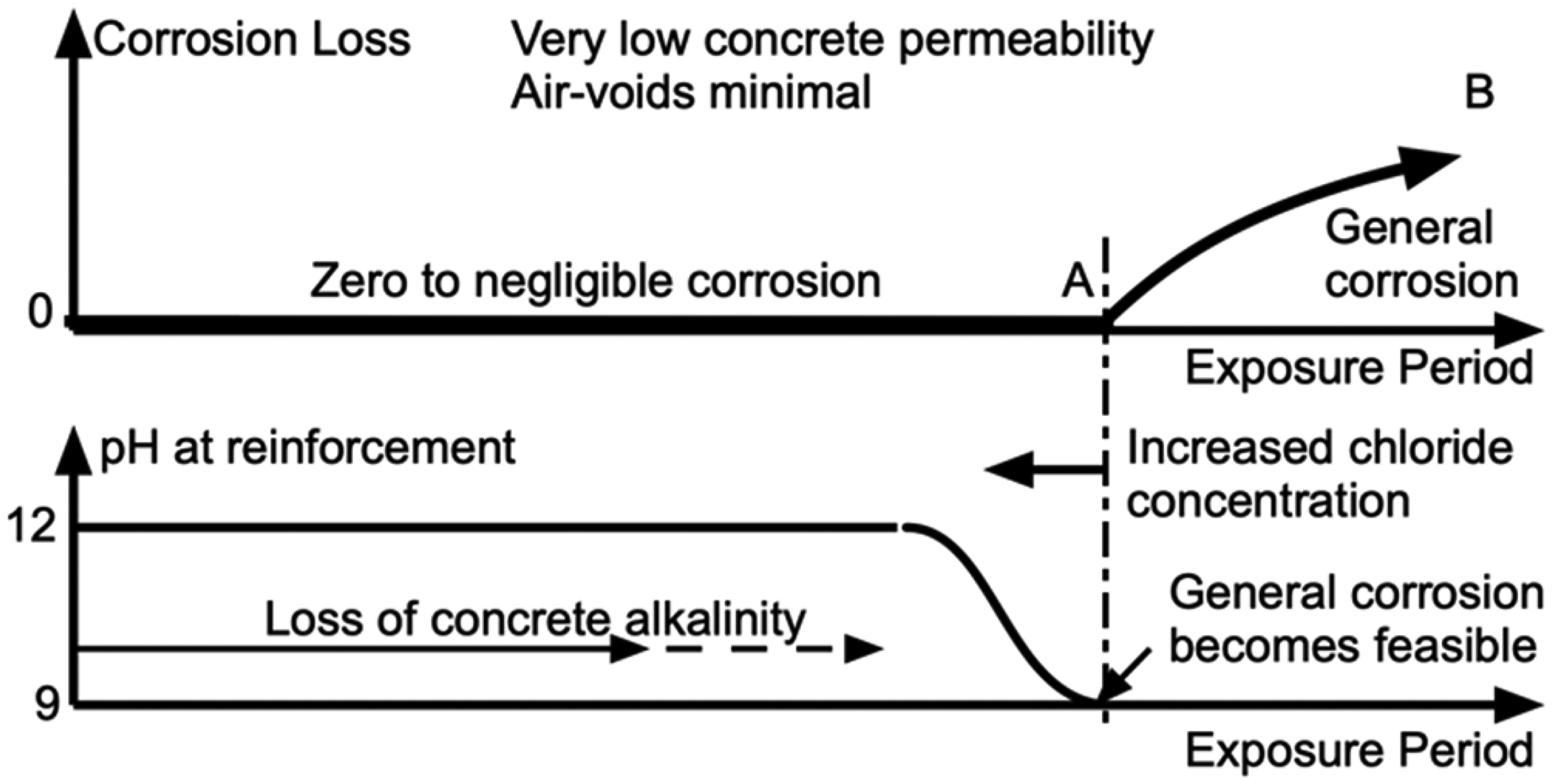
Model for corrosion loss as a function of time for concretes of very low permeability (top) and (lower) schematic development of pH at the steel bar as a function of loss of calcium hydroxide and thus porewater pH.
The effect of greater permeability of the concrete on the progression of reinforcement corrosion loss is shown in schematic form in Figure 6. There is now the likelihood of air-voids existing at the steel–concrete interface. With the presence of water in the air-voids localised (pitting and crevice) corrosion of the steel in the voids becomes feasible. This occurs primarily in phase 0-D (Figure 6), with possibly a short phase 0-C necessary for inward diffusion of water to the air-voids. Phase D-E has corrosion rate-controlled by the rate of inward diffusion of water and oxygen (likely as dissolved oxygen) through the surrounding concrete. Localised corrosion of the steel within air-voids can thus continue, at the nominal rate rpitting. Greater concrete permeability permits a higher rate of inward diffusion and thus a higher rate of corrosion, but it also permits a degree of migration of corrosion products into the concrete matrix surrounding the steel. This latter mechanism has long been identified for permeable concretes and associated with inhibition of the rate of corrosion in phase D-E. 44 As noted above, such behaviour has been observed, for example, in long-term experimental programs and attributed in part to rust build-up.11,12 This behavioural pattern is implicit in observations for some concrete structures in practice. 7
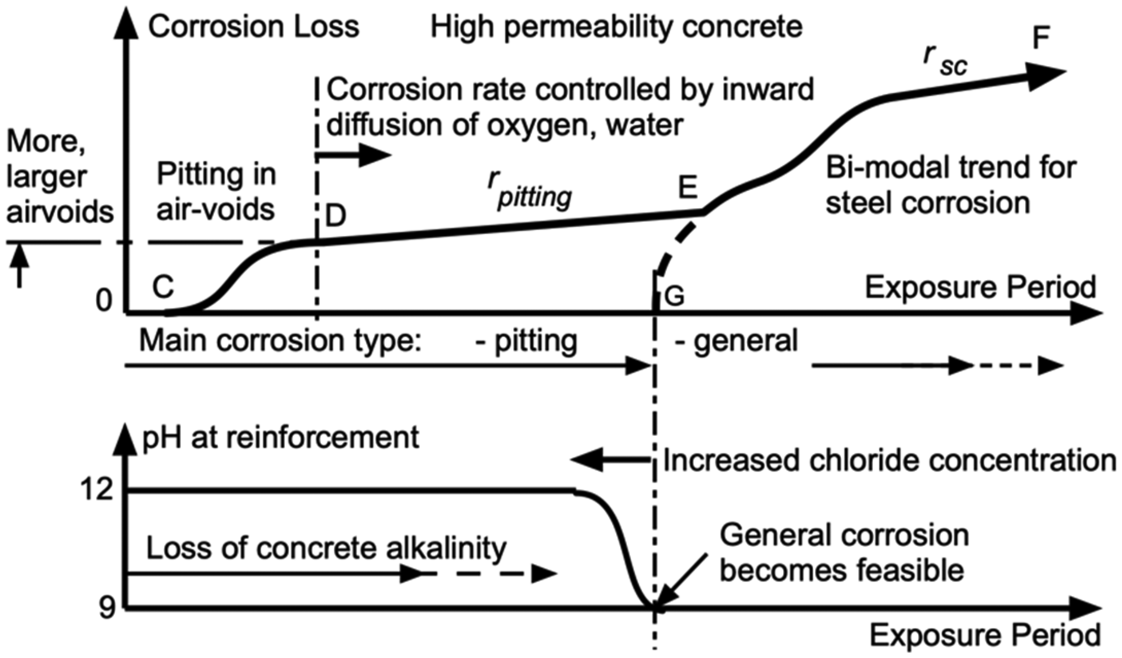
Schematic model for corrosion loss as a function of time for concretes of high permeability.
As the (perhaps slow) build-up of corrosion products continues there likely will be further physical damage of the surrounding concrete including cover, with loss of the protective effect of the surrounding concrete commencing, schematically, at point E in Figure 6. It is similar to point A in Figure 5. In both cases, the loss of protection and the circum-neutral pH means that general corrosion has become feasible. The developing corrosion loss is shown as phase E-F. In that phase, the corrosion of the (now poorly protected) steel can be expected increasingly to follow the corrosion behaviour of bare steel in water. This has been shown to be bi-modal in character, irrespective of whether the water is chlorinated or fresh. 45 That bi-modal behaviour is shown schematically in phase E-F of Figure 6. Consistent with that model, the long-term rate is shown as rsc. 29
Discussion
The models in Figures 5 and 6 and the comments about the mechanisms and theory involved for each of the phases indicate that the initiation and the development of reinforcement corrosion is more complex than ‘chloride-induced corrosion’ for initiation and the Tuutti model 46 (Figure 7) for corrosion development. However, there are some superficial parallels.
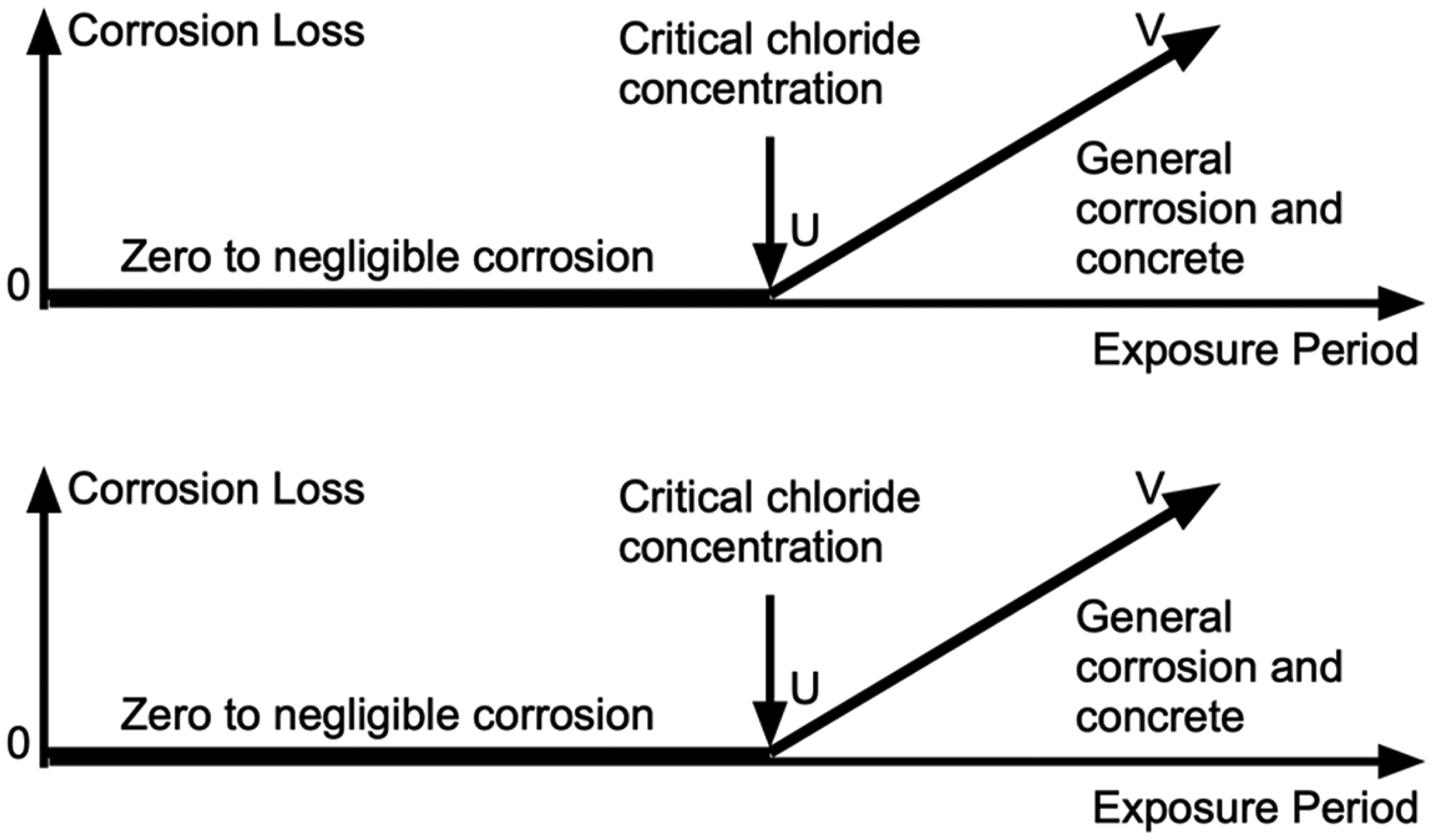
The classic Tuutti model showing a period (0-U) during which chlorides are assumed to build-up at the steel to reach a (‘critical chloride’) concentration (at U) sufficient for commencement of general corrosion in phase U-V.
With some leeway and interpretation, both Figures 5 and 6 can be simplified to the classical model in Figure 7. The first part 0-U (Figure 7) can be considered a first approximation for the development of corrosion loss, phase 0-A in Figure 5 and, with a somewhat greater degree of approximation, that of phases 0-C-D-E in Figure 6. In both cases, this is followed by a much greater average rate of corrosion, after A and E, respectively. The linear phase U-V in the classical Tuutti model Figure 7 can be considered a first approximation for phase A-B in Figure 5 and for phase E-F in Figure 6, even though the corrosion mechanisms involved are considerably different.
For the Tuutti model, the sharp increase in corrosion rate at point U has been assumed the result of ‘chloride-induced’ corrosion of the steel. Conventionally this is associated with the notion of a ‘critical chloride concentration’ having been reached at the steel, with subsequent corrosion under chloride-induced conditions (e.g. 7 ). However, in the light of the above analysis based on the corrosion feasibility conditions as defined by the Pourbaix diagram, it can now be seen that the logic long accepted for explaining the characteristic Tuutti model is implausible. At best, the Tuutti model can be viewed as a simplification of the more complete models in Figures 5 and 6.
As indicated in the comments leading to Figures 5 and 6, chlorides influence the reinforcement corrosion process only through their effect on the concrete and specifically by increasing the rate of dissolution of calcium hydroxide and thus the rate at which it can leach out of the concrete. Higher concentrations of chlorides cause faster dissolution 42 and thus earlier loss of calcium hydroxide to maintain the concrete pH at the steel bars.
The accelerated loss of loss calcium hydroxide and associated pH at the steel bars also advances the onset of general corrosion in time (cf. A in Figure 5 and E in Figure 6). Superficially, this can be considered to be responsible for the notion that chlorides are directly responsible for the earlier onset of corrosion, as in the notion of ‘chloride-induced corrosion’. However, this can now be seen to be an erroneous interpretation – the chlorides ‘merely’ cause a faster loss of pH, that then, when the pH drops below about 9, permits general corrosion of the steel. Further, it should now be clear that there is no link between ‘initiation’, subsequent inhibition (phase D-E in Figure 6), and long-term corrosion (phases A-B and E-F) resulting from loss of concrete alkalis.
In summary, the above analysis shows that the role of chlorides in marine corrosion of steel reinforcement in concrete largely is limited to increasing the rate of dissolution and hence loss by diffusion of calcium hydroxide, thereby bring forward to time to the changeover at points A and E in Figures 5 and 6. This effect likely is responsible for the earlier hypothesis that the mechanism governing period of time for phase 0-A in Figure 7 (the Tuutti model) is the diffusion of chlorides from the exterior environment into the concrete and that corrosion becomes feasible (‘initiates’) when a ‘critical chloride concentration’ is reached (e.g. 7 ).
It is apparent from the literature that the earlier work did not reference thermodynamic requirements along the lines given above and did not consider the role of MnS inclusions for practical steels. In part this may explain the wide variability in experimental results for attempts to determine the ‘critical chloride concentration’. It can now be seen to be irrelevant.
The practical implications of the above are that corrosion of reinforcement should not be a critical issue for well-compacted, low permeability concretes with adequate cover thickness, irrespective of chloride content, even over extended periods of exposure. In this context, it is noted that guidelines for what constitutes adequate compaction largely are aimed at ensuring adequate concrete strength.47,48 They do not focus on concrete permeability or reduction of air-voids at the steel–concrete interface. Lower permeability can be achieved by the use of waterproofing agents or similar, or self-compacting concretes. However, their effectiveness regarding permeability for leaching calcium hydroxide and for air-void reduction warrants investigation. Similarly, research attention might now be given to evaluation of optimal permeability for control of alkali loss, and for desirable limits on air-voids, matters not previously seen as central to reinforcement corrosion in marine conditions. Such efforts should include the potential effects of uncertainty due to cement content, aggregate type and size, aggregate-cement ratio, water-cement ratio, etc., noting that some of these factors can be seen in the published experimental results.8,41 In turn, the outcomes from such investigations will aid establishment of appropriate risk assessment procedures.
In summary, the practical outcome of the above analysis is that rather than focussing on keeping the chloride content to less than some empirical value, attention should be given to achieving concretes with low permeability, low content of voids particularly at the concrete–steel interface and on retaining concrete alkalis. Achieving these aims has implications for adequate placement and compaction of concrete around reinforcement bars, for bar spacing and placement and for adequate cover, with, for the latter, measures to control the severity and, in particular, the depth of concrete cracking. On the other hand, for assessment of existing reinforced concrete structures, less emphasis should be placed on chloride concentrations at and around steel reinforcement bars and more emphasis placed assessing the reserves of remaining concrete alkali, and in particular calcium hydroxide and associated concrete pH. Assessments also should consider observation of evidence of rust staining and localised physical damage of concrete. Finally, in both design and assessment, attention should be given to other potential adverse effects, in particular mechanical damage such as through the loss of concrete protectiveness by alkali-aggregate reactivity. 29
Conclusion
The effect of chlorides on corrosion of reinforcement in reinforced concrete was re-evaluated herein, with the following outcomes.
Initiation of corrosion of steel in the high pH environment of new concretes is feasible through localised (pitting) at MnS inclusions within wet air-voids in the concrete at the steel–concrete interface and this is irrespective of the precise chloride concentration. It follows that the notion of a ‘critical chloride concentration’ is not consistent with thermodynamics of corrosion and therefore has no fundamental meaning and is responsible for the wide variability in experimental efforts to determine such a concentration. Wide-ranging field and experimental evidence shows that any initiation of reinforcement corrosion continues at a negligible or low rate for low permeability, well-compacted concretes with adequate cover thickness that govern the rate of inward diffusion of oxygen (and water) to the air-voids while general corrosion of the steel remains inhibited by the pH of the concrete. Long-term corrosion of the steel commences one the loss of calcium hydroxide and associated concrete pH has become sufficient at the steel surface to permit general corrosion to occur. For new structures, attention should be given to achieving concretes with low permeability and adequate cover while investigation of existing structures should focus on remaining alkalis in the concrete at the steel and observation of evidence of rust damage.
Footnotes
Acknowledgements
The continued support from the University of Newcastle, Australia is appreciated, as are the discussions and support of Prof. Igor Chaves, Goran Simundic, Ian Jeanes and other Civil Engineering laboratory staff who contributed to the experimental work summarised herein, the support of Prof Chun Qin Li (now at RMIT University, Melbourne), Joost Gulikers (Netherlands Ministry of Works) and the staff at Auchmuty Library at the University of Newcastle, Australia.
Funding
The author received no financial support for the research, authorship, and/or publication of this article.
Declaration of conflicting interests
The author declared no potential conflicts of interest with respect to the research, authorship, and/or publication of this article.