
Abstract
The corrosion in the aqueous environment of CO2–H2S–O2–SO2 is extremely severe, causing frequent failures of pipeline and posing a challenging issue for material selection. This paper drew on excellent standards and past experiences to provide a suitable method for selecting materials. The method consisted of four components: standard primary selection, corrosion evaluation selection, mechanical property selection, and economic final selection. A case study demonstrated that the applicable materials for the environment (total pressure of 1.5 MPa, temperature of 30–120 °C, H2S content of 0.1–1.5%, CO2 content of 8–55%, SO2 content of 0–0.00015% and O2 content of 1–3%) were composed of 2Cr13 or 316L. Additionally, the main control factors for corrosion rate were ranked as follows: O2 > H2S > temperature > CO2 > SO2. And a reduction in mechanical properties was observed for 2Cr13, 316L, and 825 after corrosion.
Introduction
The matter of energy security has always been a great concern, with the safety of pipelines being an issue directly intertwined with it. 1 The safety of pipelines is often closely related to their inherent properties and environment.2,3 At present, the excellent quality and cost-effectiveness of carbon steel have made it often used in various process treatment systems in oil and gas fields. However, in harsh corrosive environments, certain types of carbon steel are highly inapplicable and can undergo rapid corrosion perforation failure in the short term.4–6 The corrosion failure of pipeline materials is a very inevitable and difficult issue, which significantly impacts the secure transportation of oil and gas products. 7 The RL block of an oilfield, for instance, encountered severe corrosion issues and limited applicability of carbon steel materials due to the presence of H2S, CO2, SO2, and O2 in the pipeline medium. 8 Therefore, selecting and designing superior pipeline materials to effectively mitigate corrosion failure has emerged as a crucial and significant research concern.
The selection of materials for oil and gas pipelines involves numerous standards. ISO 15156 9 defines the general principles, requirements, and recommended methods for evaluating and choosing metal materials applicable for pipelines exposed to H2S environments in oil and gas production and desulfurisation units. API Spec 5L 10 and ISO 3183 11 both define the design, manufacturing, and inspection requirements for pipelines. However, ISO 3183 also includes the installation and operation requirements for pipelines, including provisions for construction, commissioning, operation, maintenance, and repair. Additional standards for material selection include European EN 10208, 12 Chinese GB/T 9711, 13 Japanese JIS G 3466, 14 Canadian CAS Z245, 15 German DIN 17172, 16 Australian AS 2885, 17 etc. The aforementioned standards primarily include the manufacturing process, chemical composition, mechanical properties, corrosion resistance, dimensions, weight, anti-corrosion measures, and other requirements for various pipeline materials. These standards exhibit significant applicability to sour gas CO2/H2S environments as well as O2 environments. However, there is a lack of recommended material applicability specifically in CO2–H2S–O2–SO2 aqueous environments. Further determination is necessary to establish a solid foundation for selecting pipeline materials during the design stage.
The corrosion rate is commonly utilised as an evaluation criterion for analysing the resistance of specific materials to corrosion in various harsh environments. A significant number of advancements have been achieved through corrosion experimental methods for the evaluation of pipeline materials in on-site service, specifically in CO2 environments18–20 and CO2–H2S environments.21–24 A consensus has been reached regarding the corrosion mechanism in a CO2 environment. The formation of FeCO3 on the material’s surface exhibits certain protective properties. However, the deposition and density of this film are closely influenced by variables such as temperature, 25 partial pressure, 26 and flow rate. 27 In CO2–H2S environments, the most influential factor is the partial pressure ratio of CO2/H2S. 28 The generated FeS and FeCO3 product films exhibit significant differences at different ratios, directly impacting material corrosion rates. The addition of O2 in CO2–H2S–O2 and CO2–H2S–O2–SO2 environments further complicates the corrosion mechanism. Firstly, as a depolarising agent, O2 promotes the cathodic reaction and acts as an oxidant to degrade the dense films of FeCO3 and FeS, thereby facilitating corrosion. Secondly, the synergistic effect between O2–H2S and O2–SO2 significantly accelerates corrosion rates and enhances pitting corrosion formation.29,30 Therefore, studying these two environments is highly valuable and provides essential insights for pipeline material selection.8,31–34 It can also be inferred that selecting materials for CO2–H2S–O2–SO2 environments poses significant challenges.
In addition to considering the corrosion rate index, the process for materials also takes into account their mechanical properties, as there is a certain degree of reduction in these properties after corrosion.35,36 Currently, pipeline material selection is primarily based on comparing the mechanical properties evaluation results of pipes upon leaving the factory with established standards, ensuring they meet requirements before being put into service. However, few studies incorporate the mechanical properties results from corroded service environments as a basis for pipeline material selection, that is, evaluating whether the mechanical properties before and after corrosion meet requirements.
To summarise, the primary purpose of this paper is to fill in the existing gaps in standards and literature pertaining to material selection methods and applications in CO2–H2S–O2–SO2 aqueous environments. By integrating numerous exemplary standards and leveraging past experiences in material selection, a novel method for selecting materials applicable for gathering and transportation pipelines in CO2–H2S–O2–SO2 aqueous environments has been developed. It includes four components: standard primary selection, corrosion evaluation selection, mechanical property selection, and economic final selection. The material selection method presented in this paper provides certain assistance and a theoretical basis for the material selection and design of pipelines in corrosive environments similar to RL blocks such as multi-component thermal fluids, fire-driven exhaust gas, and flue gas displacement.
Material selection method
Standard primary selection
The commonly associated gases in oil fields are primarily CO2 and H2S, which adhere to internationally recognised ISO 15156 material selection standards and methodologies within this corrosive environment.37,38 In the severe corrosion environments of the RL block, apart from significant quantities of CO2 and H2S, O2 and SO2 are present as small amounts of impurities, while a universally recognised method for material selection has yet to be established. If the simultaneous influence of CO2, H2S, SO2, and O2 is taken into consideration, the corrosion rate of different materials and conditions varies. Consequently, conducting experiments to select materials that meet the requirements would entail a substantial workload. Meanwhile, the sulphide stress cracking (SSC) caused by H2S needs to be further determined through experiments, which will result in an increased workload. Therefore, in order to efficiently select materials that meet the requirements, this paper proposes the idea of initially selecting recommended materials based on ISO 15156 for CO2 and H2S resistance, ensuring they also comply with ISO 15156 standards for SSC. Subsequently, the influence of SO2 and O2 on the corrosion resistance of these recommended materials is further evaluated using weight loss and mechanical properties experiments. This method enables a quick screening process to select materials that meet corrosion requirements in four gas environments.
Therefore, the selection of pipeline materials in CO2–H2S–O2–SO2 aqueous environments is primarily based on ISO 15156. According to ISO, the range of material types for carbon steel and low-alloy steel is mainly determined by considering in-situ pH value and SSC cracking severity. Firstly, the pH value of the fluid under production conditions can be determined by calculating the sum of partial pressures of CO2 and H2S (PH2S + PCO2), as shown in Figure 1. Secondly, corrosive environments with harsh conditions may cause damage that differs from SSC mechanisms. ISO classifies the severity of carbon steel and low alloy steel cracking in H2S environments into four zones based on in-situ pH and H2S partial pressure values: zone 0 does not require consideration for cracking in acidic environments, zone 1 is slightly acidic, zone 2 is moderately acidic, and zone 3 is severely acidic, as depicted in Figure 2. The selection of the zone in this paper needs to be conservative due to the influence of trace amounts of SO2. In cases where the SO2 content is high, it is necessary to consider adding the partial pressure of SO2. The appropriate materials are selected based on different acidic environmental conditions to create primary pipe specimens, as shown in Table 1. (For the sake of subsequent method elaboration, four types of primary materials are presented here, but not limited to these four. They are referred to as Steel No. 1, No. 2, No. 3, and No. 4.)
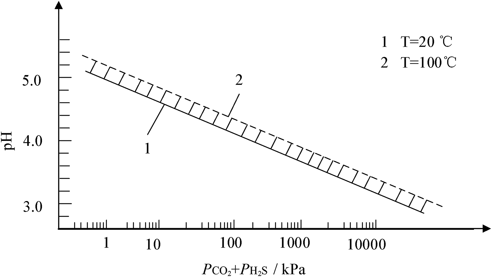
Determination of in-situ pH value under production conditions.
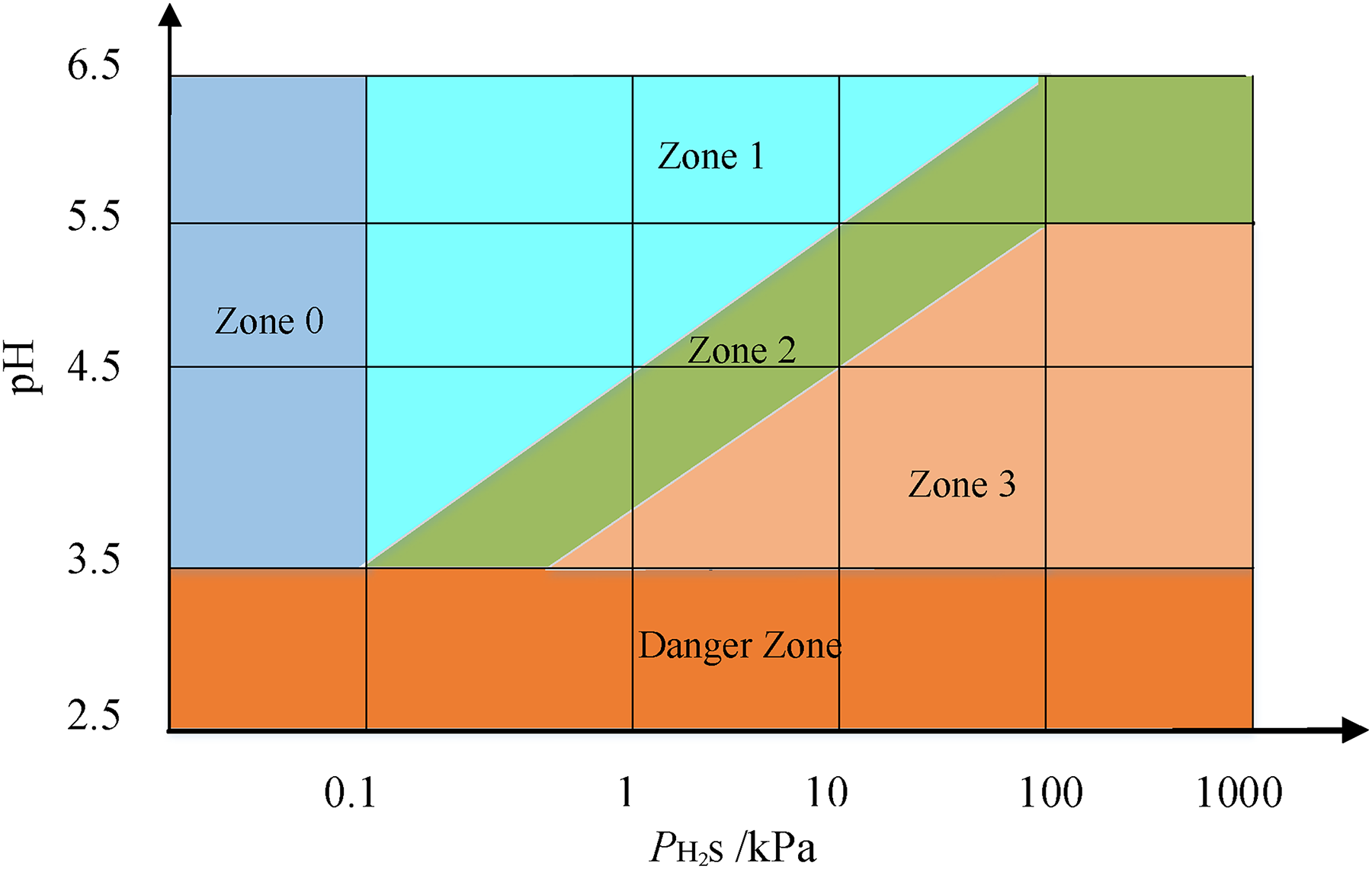
Zones of environmental severity of carbon steel and low alloy steel sulphide stress cracking (SSC).
Materials used in acidic environments.
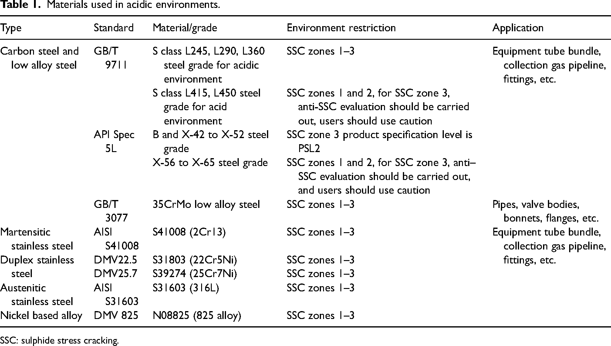
SSC: sulphide stress cracking.
Corrosion evaluation selection
Corrosion experiment testing
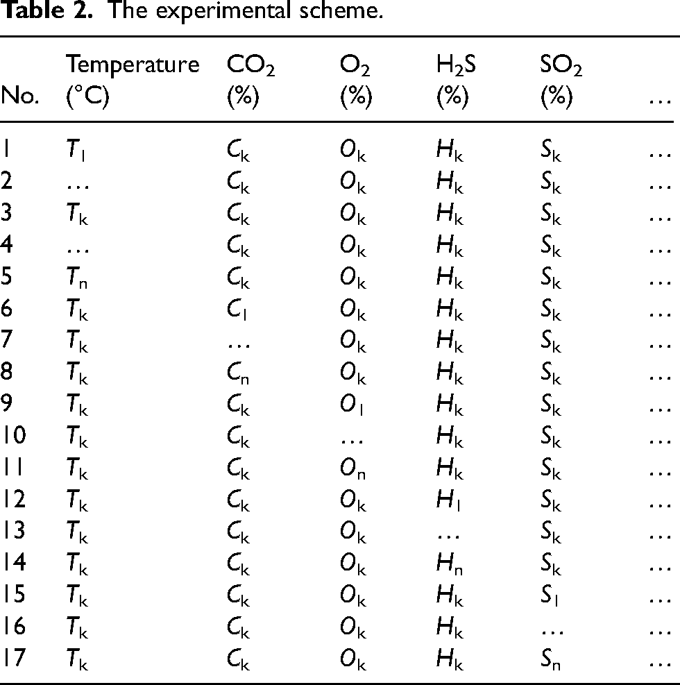
The second step involves conducting additional corrosion evaluation experiments on the four materials selected during the standard primary selection process. Because the first step only considers CO2–H2S corrosion and SSC, it is necessary to further evaluate the effects of other impurities (such as O2 and SO2). The corrosion experiment scheme was developed based on the in-site conditions of the RL block, ensuring inclusion of extreme working conditions specific to the site. The floating range of H2S content, for example, falls between H1 and Hn. Therefore, the extreme working conditions regarding H2S content primarily pertain to values of H1 and Hn, both of which must be taken into consideration when constructing the experimental scheme. The influence of various factors was studied through the control variable method because the corrosion severity was closely related to these factors (as shown in Table 2), where k denotes a set of significant or universal parameters for each factor.
The experimental scheme.
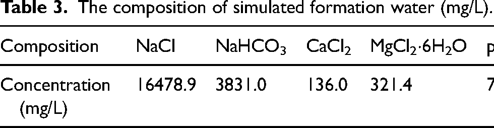
The experimental setup utilised a high-temperature and high-pressure autoclave, and the schematic diagram is shown in Figure 3. The dimensions of the specimen were 50 mm × 10 mm × 3 mm with a 6 mm aperture. Prior to the experiment, the specimen underwent step-by-step sandpaper grounding (400#, 600#, 800#, 100#, and 1200#) to ensure uniform surface roughness. The specimen was immersed in petroleum ether and anhydrous ethanol for dehydration and degreasing, each for 10 min. After drying the specimen with cold air for 10 min, it was placed in a vacuum desiccator for 24 h. Following the drying process, an electronic balance with an accuracy of 0.1 mg was utilised to measure the mass m1. The size of the specimen was measured using a vernier calliper with an accuracy of 0.01 mm, allowing for the calculation of its surface area S. Subsequently, the specimen was suspended on a support and inserted into the autoclave. Two-thirds of the autoclave volume solution (see Table 3) was poured into it, immersing the specimen completely and sealing the autoclave. Then, N2 gas was introduced into the autoclave for 2 h in order to exclude air. Temperature parameters were set and corrosive gases (CO2, O2, H2S, and SO2) were sequentially injected into the system. Finally, using N2 gas to maintain total pressure. After a 5-day corrosion test, the specimens were removed and descaled using ultrasound in a solution of hexamethylenetetramine (5 g), hydrochloric acid (100 mL, density 1.19 g/mL), and deionised water (900 mL) for 10 min.
6
Subsequently, the specimens were followed by ultrasonic cleaning with anhydrous ethanol. They were then dried at room temperature for 24 h and weighed their mass m2. The corrosion rate value was calculated according to equation (1):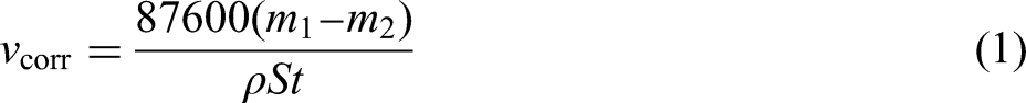
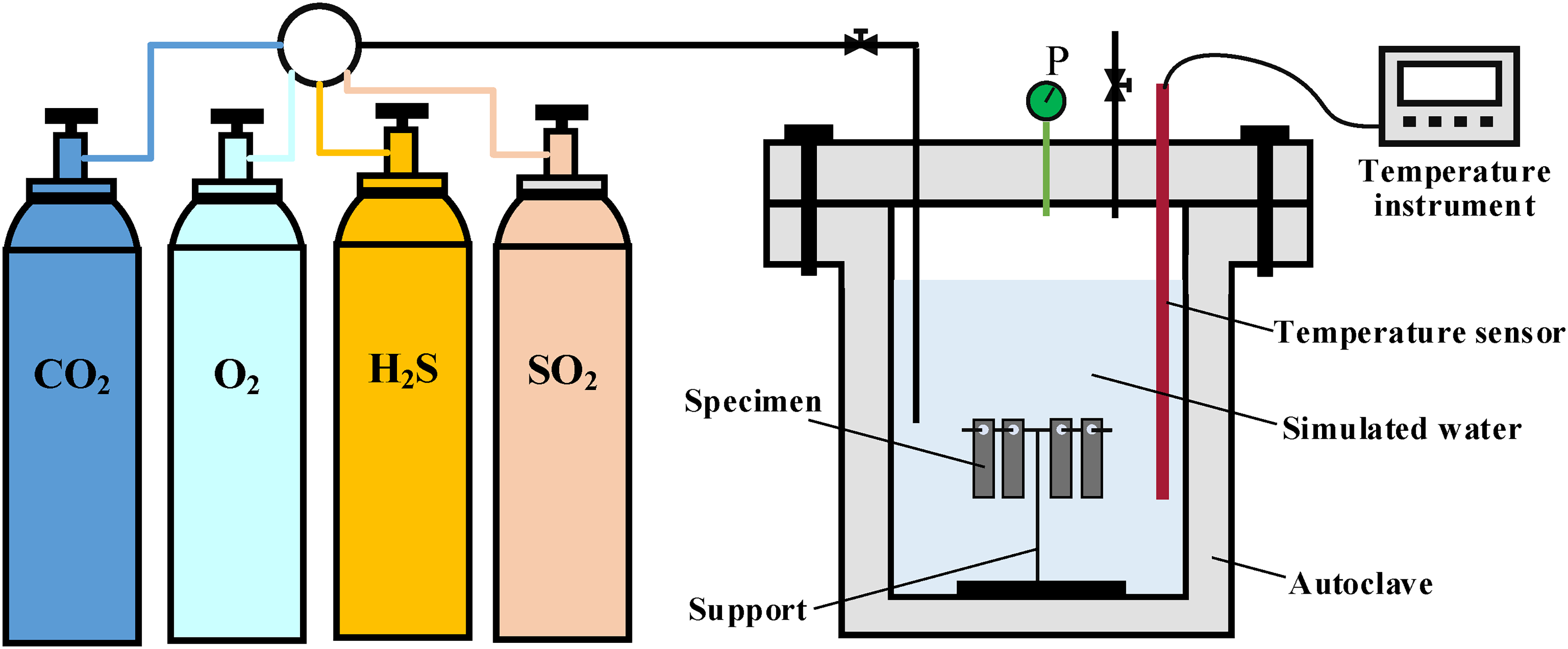
The schematic diagram of the autoclave.
The composition of simulated formation water (mg/L).
Material selection based on corrosion rate
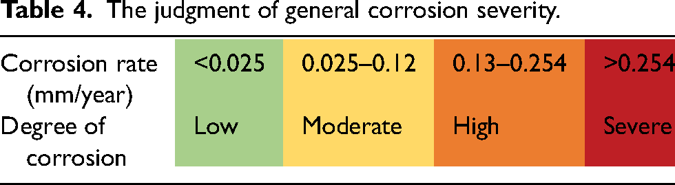
The corrosion rates are obtained by conducting experiments on four primary selected pipes under various influencing factors. After obtaining the corrosion rates of four different materials, the recommended range of materials is determined based on the corrosion rate value as a judgment index. The severity of corrosion is evaluated according to NACE RP0775–200 in Table 4. 39 The darker the colour, the more severe the corrosion. When categorising the corrosion rate as moderate (corrosion rate < 0.12 mm/year), it indicates that the material meets the selection requirements.
The judgment of general corrosion severity.
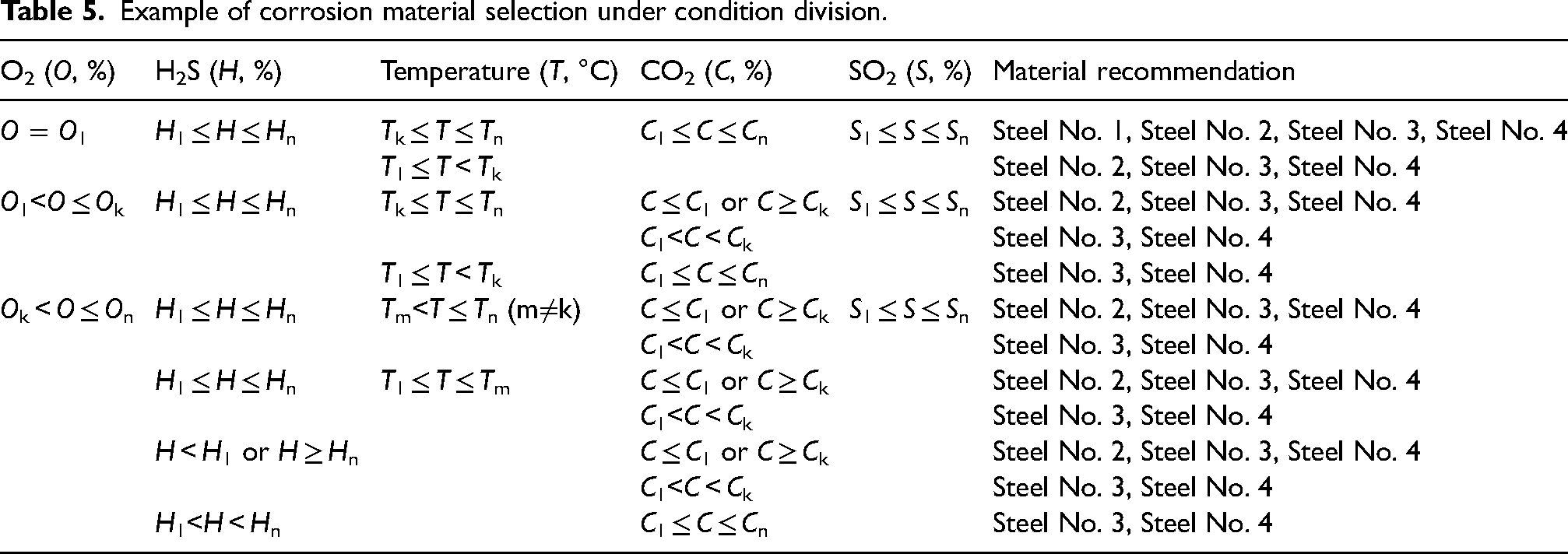
The in-site conditions corresponding to different process locations, however, exhibit inconsistency, including variations in temperature, gas content, and corrosion rate. Therefore, it is necessary to determine the material range within the corresponding division range based on the corrosion rate according to the division of different conditions. The main control factors for corrosion rate need to be determined because the division of conditions and the magnitude of corrosion rate are closely related to the values of each factor. The applied method is the mature grey correlation method,40,41 commonly employed for analysing the main control factors of multiple variable factors on a certain key factor. For instance, in this paper, it is used to discuss the main control factors of the influence of temperature/CO2/H2S/O2/SO2 on the corrosion rate, to facilitate the next analysis or the decision of condition division, corrosion prevention and control measures. Among them, the corrosion rate is taken as the reference sequence and each factor is taken as the comparison sequence to calculate the correlation degree between each factor and the corrosion rate. Then all the correlation degrees of each factor are averaged and then sorted to get the ranking of the main control factors. The sequence of main control factors is used to determine the basis of condition division. Next, the corrosion rate judgment index and the range of materials meeting this index are combined to divide the condition range for each factor, forming a corrosion material selection table in a CO2–H2S–O2–SO2 aqueous environment. Table 5 shows an illustrative example of corrosion material selection with O2 > H2S > temperature > CO2 >SO2 being the sequence of main control factors. Recommended materials can be searched based on specific process location conditions.
Example of corrosion material selection under condition division.
Mechanical property selection
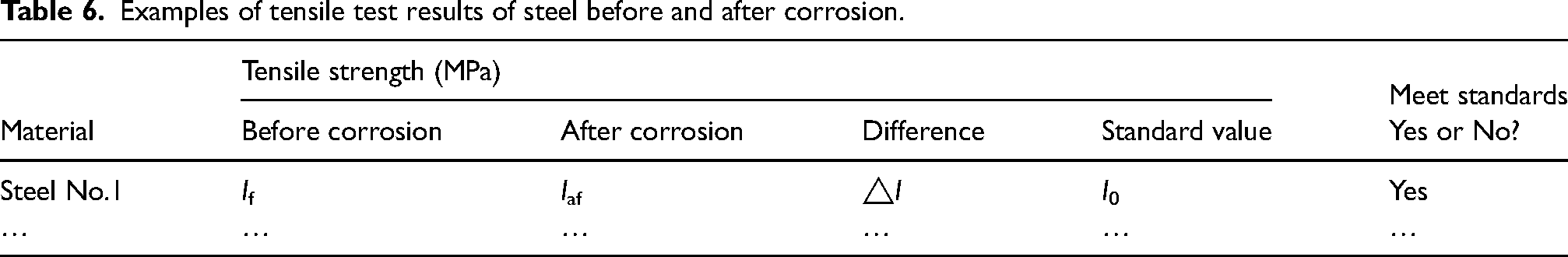
After locating the recommended materials based on the process position, the next step involves conducting tests to evaluate the mechanical properties before and after corrosion. Materials that meet the standard requirements in terms of their mechanical properties are then further selected. The evaluation of a material’s mechanical properties primarily includes tensile, impact, and hardness testing. The dimensions of the specimens are presented in Figure 4. The mechanical properties of optional materials are subjected to 5-day corrosion tests, and the experimental conditions are determined according to the conditions of specific process locations (see Table 2). Following the 5-day period, they are extracted and subjected to tensile, impact, and hardness testing alongside the uncorroded specimens. The results of the material's tensile test before and after corrosion can be recorded in Table 6, and the impact and hardness test results are similar.
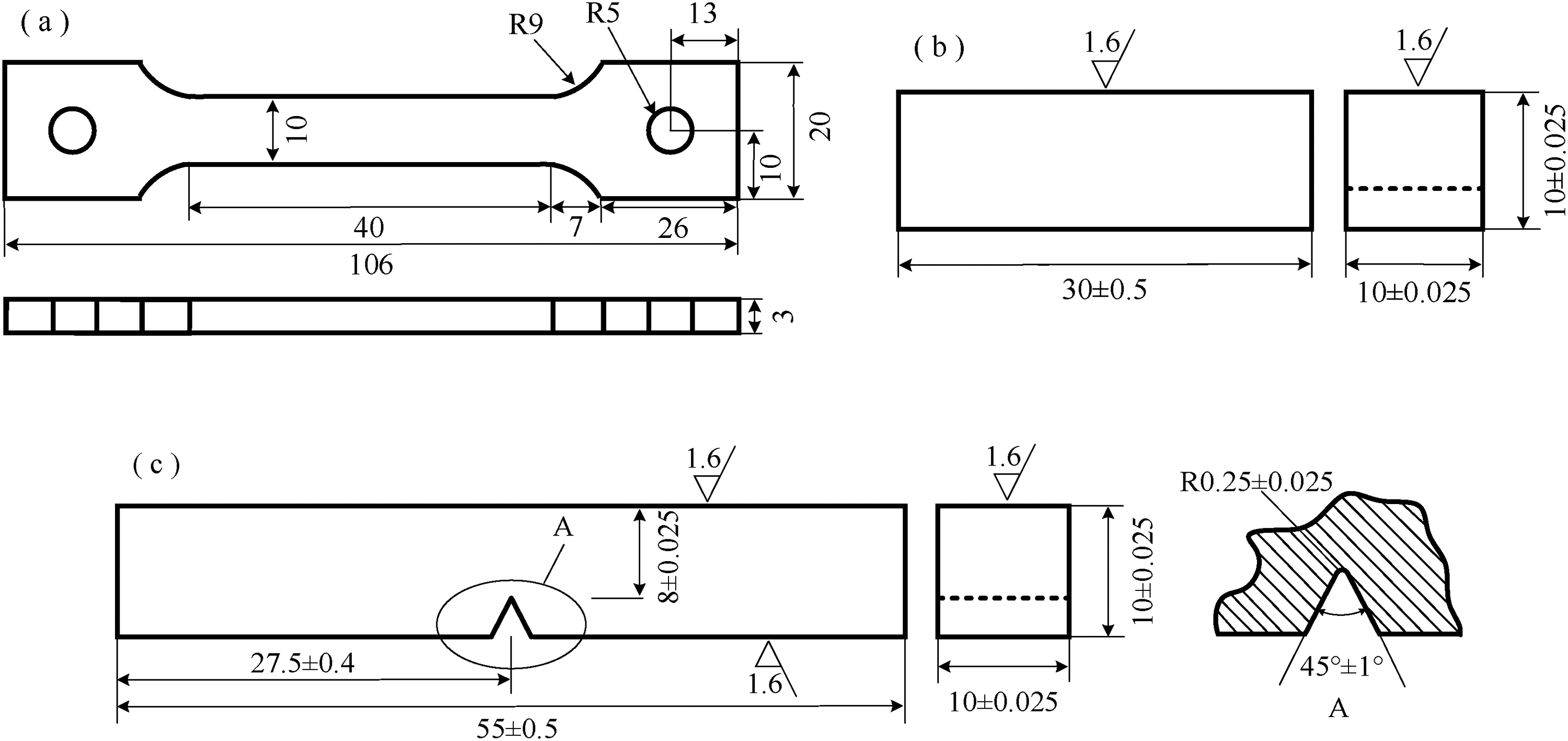
Dimensions of mechanical property size (a, tensile specimen; b, impact specimen; c, hardness specimen).
Examples of tensile test results of steel before and after corrosion.
Economic final selection
After completing the aforementioned three steps, the chosen material will be able to meet the process conditions on-site. In case there are materials available, an economic evaluation will be conducted based on their usage in the process, primarily considering factors such as material purchasing cost, installation cost, and other associated expenses. The objective is to select the material that offers optimal economic benefits. Finally, the materials selected should meet standard requirements, and undergo corrosion evaluation and mechanical properties evaluation, while also providing good economic benefits. If there are additional cost-effective options available, this section can be combined with the collected data for a detailed economic analysis.
Case application analysis
Standard primary selection analysis
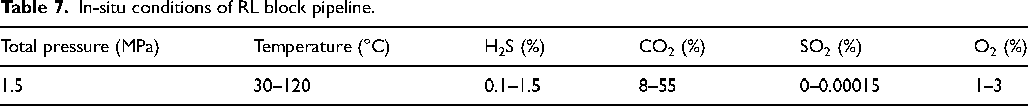
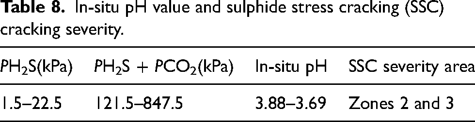
The pipeline of RL block primarily contained CO2/H2S/O2, along with a small amount of SO2, as indicated in Table 7. Among these gases, the content and temperature varied due to fluctuations in test values across different periods and process locations. The partial pressure was calculated according to the content of H2S/CO2 and equation (2). As shown in Table 8, the calculated PH2S partial pressure ranged from 0.15 to 1.5 kPa, and the PH2S + PCO2 partial pressure ranged from 121.5 to 847.5 kPa. According to Figures 1 and 2, the in-situ pH ranged from 3.88 to 3.69, with the severity of SSC falling within zones 2 and 3.
In-situ conditions of RL block pipeline.
In-situ pH value and sulphide stress cracking (SSC) cracking severity.
According to the severity of zones 2 and 3 and the integrated material selection table (Table 2), a primary selection was made for four types of carbon steel, low alloy steel, and high alloy steel as presented in Table 9.
Primary selection results of pipeline materials.
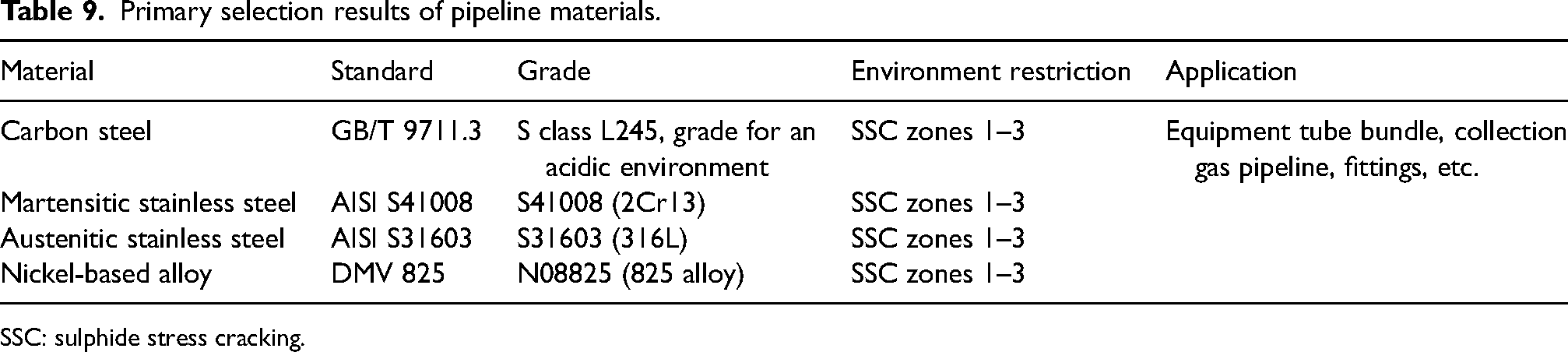
SSC: sulphide stress cracking.
Corrosion evaluation selection analysis
Corrosion rate and ranking of main control factors
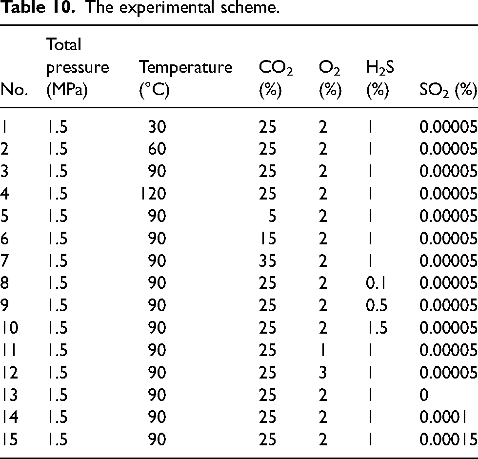
The corrosion experiment scheme (Table 10) was determined using the control variable method, considering the in-situ conditions of the RL block pipeline (Table 7), and evaluating the influence of each factor on the corrosion behaviour of four materials.
The experimental scheme.
According to the corrosion experiment testing presented in the ‘Corrosion evaluation selection’ section, Table 11 presents the corrosion rate and severity distribution of four materials. The darker the colour, the more severe the corrosion. It is evident that L245NS exhibited a high and severe degree of corrosion, while 2Cr13 primarily demonstrated moderate to high levels with a few cases being serious. Both 316L and 825 display mainly low degrees of corrosion, with one group showing moderate levels.
The corrosion rate and degree under different conditions.
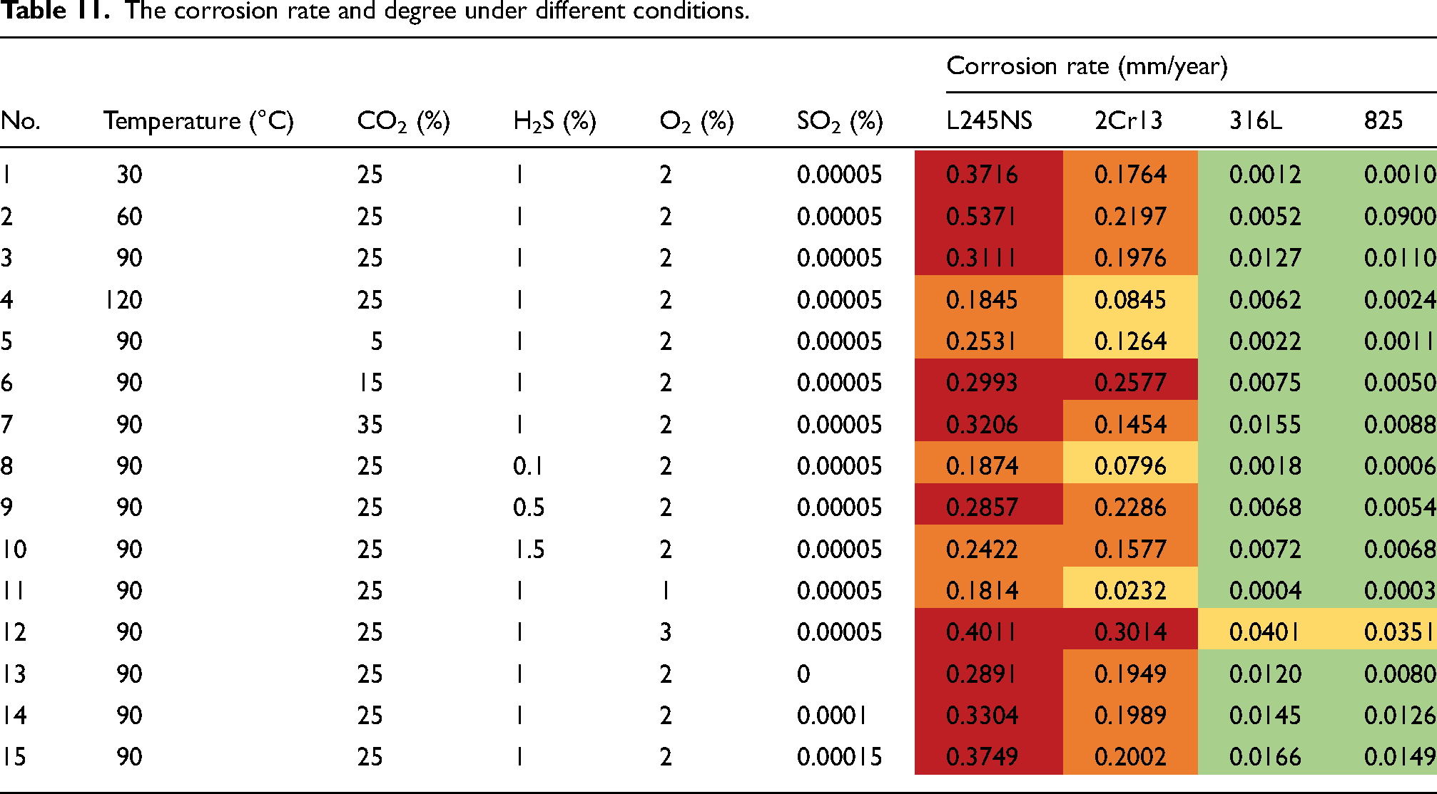
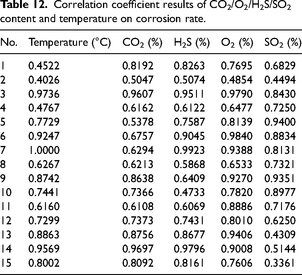
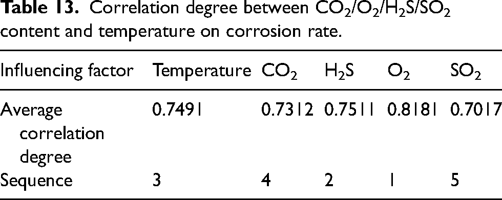
The corrosion rate of L245NS, which represents the material with the most severe corrosion, was initially chosen for grey correlation analysis in order to determine the ranking of the main control factors. Table 12 presents the correlation degree between temperature and CO2/H2S/O2/SO2 with respect to the corrosion rate, while Table 13 provides the average sub-correlation degree for each factor (each column). The correlation sequence was observed as follows: O2 > H2S > temperature > CO2 > SO2, with the highest correlation coefficient of 0.8181 found for O2, indicating its significant impact on corrosion rate. H2S and temperature exhibited similar correlation degrees, both higher than that of CO2, with coefficients of 0.7511, 0.7491 and 0.7312, respectively. SO2 had the smallest impact on corrosion rate with a coefficient of 0.7017.
Correlation coefficient results of CO2/O2/H2S/SO2 content and temperature on corrosion rate.
Correlation degree between CO2/O2/H2S/SO2 content and temperature on corrosion rate.
Material selection based on corrosion rate
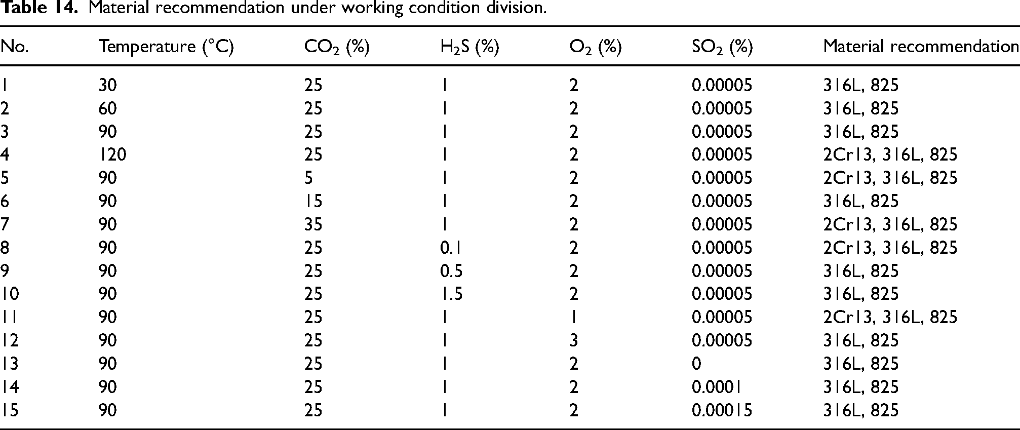
The corrosion rate judgment index of 0.12 mm/year was utilised to determine the recommended range of materials for each experimental condition in the CO2–H2S–O2–SO2 aqueous environment, forming a corrosion material selection table as presented in Table 14.
Material recommendation under working condition division.
According to the sequence of main control factors and the influence law of the corrosion rate of each factor, the working conditions were divided, and the corrosion material selection was further determined in Table 15. For instance, the O2 content ranged from 1% to 3% under working conditions (Nos. 3, 11, and 12 experiments). For an O2 content of 1%, 2Cr13, 316L and 825 materials were recommended. When O2 content was 2% and 3%, only 316L and 825 materials were recommended. Therefore, O2 content was divided into three ranges [0, 1], (1, 2) and [2, 3] according to the recommended materials. The higher the O2 content was, the more serious the corrosion would be. It was inferred that the corrosion degree of O2 content [0, 1] was lighter than that of 1%, and the available materials were 2Cr13, 316L and 825. The prerequisite conditions for experiments Nos. 3, 12, and 13 were as follows: H2S, CO2, and SO2 contents of 1%, 25%, and 0.0005%, respectively, along with a temperature of 90°C. Subsequently, the influence of H2S content (0.1–1.5%, test Nos. 3, 8, 9, and 10) was studied according to the main control sequence. The corrosion rate reached its maximum when the H2S content was 1%, while the O2 content was 2%. Therefore, it was inferred that the corrosion degree at O2 content [0, 1] and H2S content [0.5, 1.5] was lower than that at O2 content 1% and H2S content 1%. This indicates that the corrosion rate was below a corrosive index of 0.12 mm/year and the recommended materials could choose 2Cr13, 316L and 825, but the recommended results were all based on the temperature of 90 °C. Further analysis was made on the recommended materials within the temperature range under O2 content [0, 1] and H2S content [0.5, 1.5]. The influence of temperature was shown in the experimental results of Nos. 1, 2, 3, and 4. The corrosion rate was found to the ranking of 60 °C > 90°C > 30°C > 120°C when the O2 content was at 2% and H2S content was at 1%. It can be inferred that three kinds of material can be selected within the range of temperature [0, 30]∪[90, 120], with O2 content [0, 1] and H2S content [0.5, 1.5]. The corrosion rate within the range of (30, 90) may be higher than 90 °C, which was divided into the recommended ranges of 316L and 825 steels. However, the temperature division was based on the conditions of CO2 and SO2 content of 25% and 0.00005%. According to the experimental results from Nos. 3, 5, 6, and 7, it was found that the corrosion rate followed the sequence of 35% > 25% > 15% > 5% at an O2 content of 2%, H2S content of 1%, and a temperature of 90 °C. Three kinds of material could be selected within the range of O2 content [0, 1], H2S content [0.5, 1.5], temperature [0, 30]∪[90, 120] and CO2 content [0, 25]. Within the range of CO2 content (25, 35), there was a high probability that the corrosion rate of 2Cr13 was greater than the corrosion index, which was divided into the recommended range of 316L and 825 materials, and the SO2 content was 0.00005%. Finally, based on group Nos. 3, 13, 14, and 15, it was found that low SO2 content had little influence on the corrosion rate, which was uniformly divided into [0, 0.00015].
Corrosion evaluation selection results under the working conditions division.
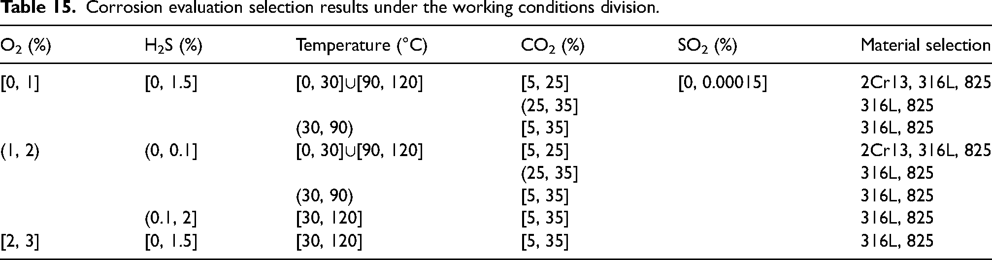
In addition, the recommended materials with O2 content in the range (1, 2) and [2, 3] were determined by the same working condition division method, as shown in Table 15. Corrosion material selection in Table 15 is only applicable to material selection in the in-situ condition range in Table 7. However, it also holds certain application value for other similar conditions.
Mechanical property selection analysis
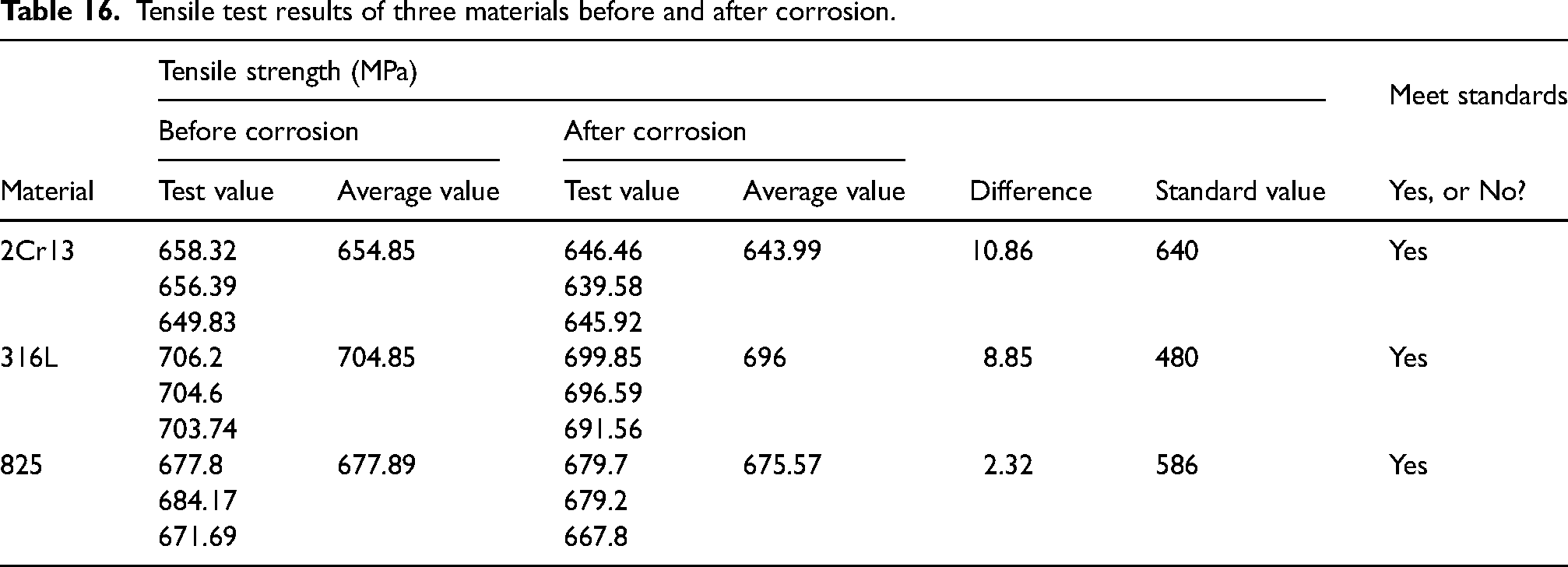
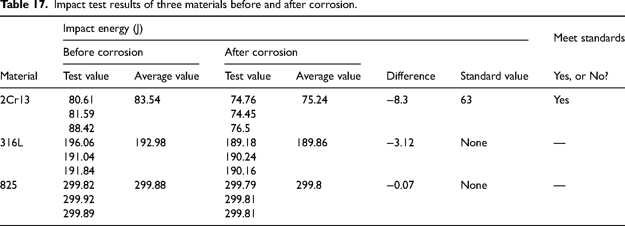
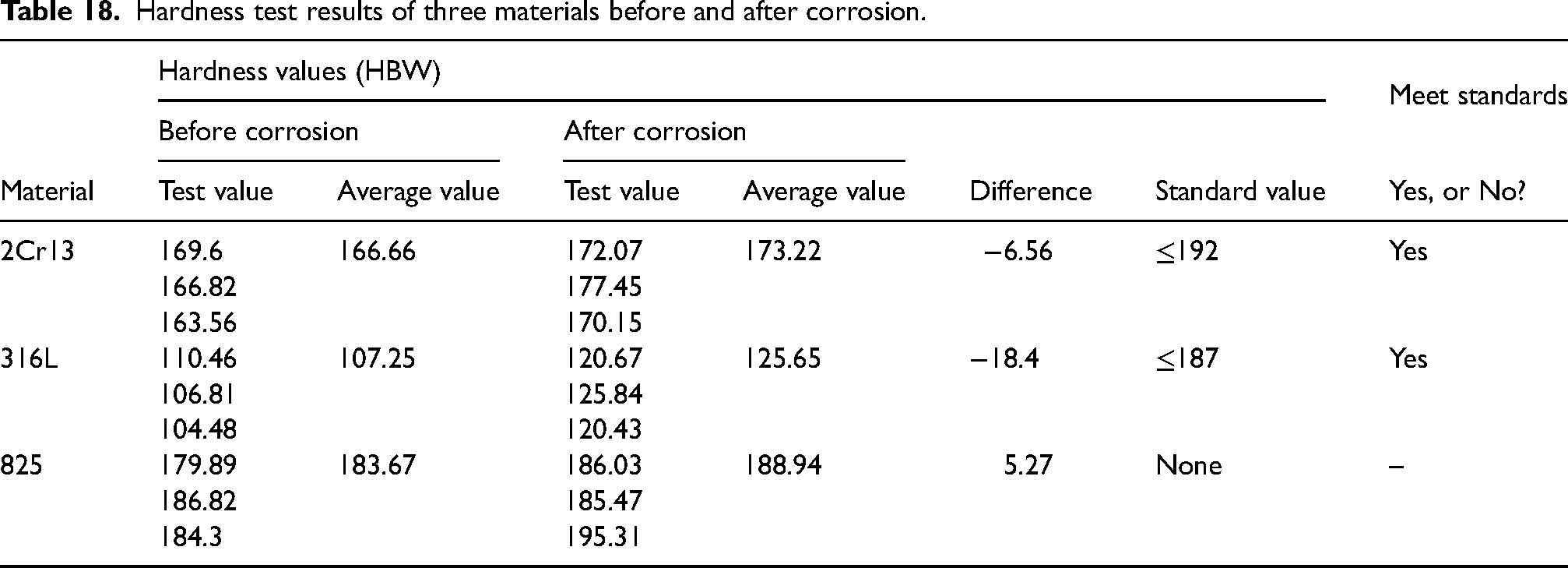
The results presented in Table 18 indicate the applicability of three recommended materials: 2Cr13, 316L, and 825. However, it should be noted that while these materials are deemed applicable based on corrosion evaluation, their mechanical properties may not fully meet the specified requirements. Therefore, it is essential to evaluate whether the mechanical properties (tensile strength, impact energy, and hardness) meet the standards before and after corrosion. Tables 16–18 present the values of tensile strength, impact energy, and hardness for the three materials before and after corrosion. Among them, the most severe corrosion condition was selected for conducting the corrosion experiment (Table 11, No. 12), as it fulfilled all requirements in both this condition and other conditions. The results indicated that the mechanical properties of all three materials exhibited a slight decrease following corrosion, albeit within acceptable limits. The mechanical properties before and after corrosion all met the requirements, and all of them could be used as recommended materials. The ‘None’ in the table means that the material execution standard does not give specific requirements for the mechanical property index. In practical applications, the purchaser has the option to specify their desired mechanical property index from the manufacturer.
Tensile test results of three materials before and after corrosion.
Impact test results of three materials before and after corrosion.
Hardness test results of three materials before and after corrosion.
Economic Brief Analysis
In the economic calculation of this case, the costs associated with maintenance and replacement due to corrosion or defect damage of pipelines were not considered, as well as the expenses related to purchasing and operating corrosion inhibitors and filling equipment (including equipment maintenance and electricity charges). One-time input costs of materials were mainly taken into account, including acquisition costs and installation costs, among which acquisition costs include material costs, pipeline processing and manufacturing costs. According to the design document for the pilot project on pipeline material selection (designed for a 10-year period) in the RL block, the one-time cost of 2Cr13 was lower than that of 316L and 825, amounting to 4.42 million RMB, 11.45 million RMB, and 13.22 million RMB, respectively.
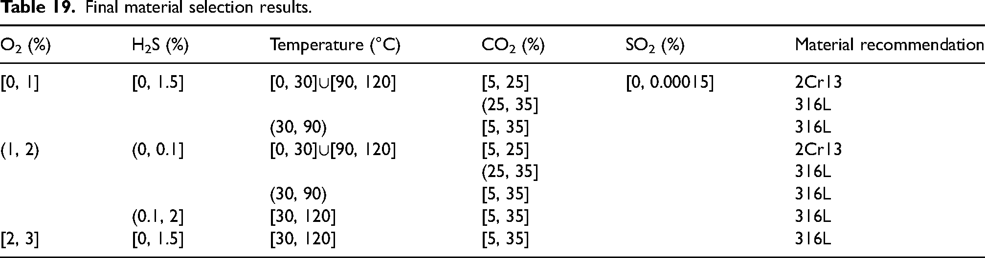
Therefore, considering the economic benefits of the three recommended materials, Table 19 shows the material selection guide for pipelines CO2–H2S–O2–SO2 aqueous environments, with 2Cr13 and 316L being the preferred choices. The selection and application of 2Cr13 and 316L need to be determined based on the specific process conditions in the environment. It is important to reiterate that the recommended material listed in Table 19 is only the applicable-situ condition range mentioned in Table 7. The method presented in this paper can assist in determining the most applicable recommended material for similar oilfield conditions.
Final material selection results.
Conclusions
This paper presented a novel method for material selection applicable for pipelines in CO2–H2S–O2–SO2 aqueous environments, including four components: standard primary selection, corrosion evaluation selection, mechanical property selection, and economic final selection.
The final materials utilised in the aqueous environment of CO2–H2S–O2–SO2 (with a total pressure of 1.5 MPa, temperature of 30–120 °C, H2S content of 0.1–1.5%, CO2 content of 8–55%, SO2 content of 0–0.00015% and O2 content of 1–3%) were determined as being composed of 2Cr13 and 316L. The selection and application of 2Cr13 and 316L should be determined based on the specific process conditions in the pipeline location to achieve both economic efficiency and safety goals.
The main control factors for corrosion rate in the aqueous CO2–H2S–O2–SO2 aqueous environment were ranked as follows: O2 > H2S > temperature > CO2 > SO2.
The mechanical properties of 2Cr13, 316L, and 825 exhibited a reduction trend after corrosion.
Footnotes
Data availability statement
The data that support the findings of this study are available on request from the corresponding author. The data are not publicly available due to privacy or ethical restrictions.
Author contributions
Kexi Liao: Review & editing, funding acquisition, and supervision. Jihui Leng: Methodology, investigation, and writing – original draft. Yongbo Yan, Tengjiao He, Xidi Lv, Xin Liu. Min Qin, Shuai Zhao, and Y. Frank Cheng: Investigation and visualisation.
Declaration of conflicting interests
The authors declared no potential conflicts of interest with respect to the research, authorship, and/or publication of this article.
Funding
The authors disclosed receipt of the following financial support for the research, authorship, and/or publication of this article: This work was funded by the National Natural Science Foundation of China (52174062), the Natural Science Foundation of Sichuan Province (2023NSFSC0420), and the Research and Innovation Fund for Graduate Students of Southwest Petroleum University (2022KYCX010).