
Abstract
Ensuring consistency between Mechanical, Electrical, and Plumbing (MEP) schema drawings and Building Information Models (BIM) is essential for design accuracy and minimizing data discrepancies in construction projects. While BIM provides detailed 3D visualizations of building components, schematic drawings remain crucial for capturing the logical and functional relationships within early-stage designs. However, discrepancies between these two representations often arise, necessitating extensive manual verification. This study introduces a conceptual framework for automated cross-validation between MEP schema drawings and BIM models by leveraging semantic representations. The framework utilizes AI-driven technologies, particularly Large Language Models (LLMs), to extract structured knowledge from both schematics and BIM data, translating this information into machine-readable formats based on the Brick ontology. By integrating semantic web technologies and multimodal processing, the proposed framework effectively identifies inconsistencies in airflow distribution, system connectivity, and performance parameters. This approach significantly enhances the efficiency and accuracy of design validation, minimizes data discrepancies, and fosters interoperability among heterogeneous data sources. Initial findings demonstrate the scalability and effectiveness of semantic-based validation, suggesting substantial benefits for MEP-BIM integration. Future research will extend the framework to additional MEP domains, including electrical and plumbing systems, and further refine AI-based recognition methods.
Keywords
Introduction
Over the years, the construction industry has been characterized by its complexity and the need for integrating multiple actors, who must be coordinated to ensure efficient project execution and the successful realization of physical structures. 1 Data generated during design and construction phases is used for facility management, which can span from a few years to several decades. Various technological transformations were therefore implemented to make the whole process more efficient and feasible to manage. A major shift was the replacement of manual drawing boards with computer-aided design (CAD). 2 This transition not only accelerated daily tasks but also enabled more efficient revisions and project modifications. After the successful implementation of computers into AECO workflow, the next significant digitalization step was made by the International Alliance for Interoperability (IAI) in 1994, nowadays known as buildingSMART. 1 In 1997, IAI released the Industry Foundation Classes (IFC), promoting industry-wide interoperability, standardisation, and productivity improvements. IFC became an integral component of modern BIM methodology, supported by the ISO 19650 standard on information management across the entire lifecycle of construction projects. 3
Despite advanced modelling tools and the rapid development of new IFC versions, this format still does not cover the full span of documentation required during the construction process.1,3 Mechanical, Electrical, and Plumbing (MEP) systems require detailed 3D modelling to represent equipment sizes, ducts, air terminals, and fire dampers as the final outcome of the design process. This domain is characterized by engineers starting projects with the planning and calculation phase, which is reflected in schema-based drawings. 4 These schematic representations are developed during the early-stage design (RIBA Stage 2) as the first part of MEP documentation, capturing the logical and functional relationships within the building systems. 5 Serving as a structured repository of domain-specific knowledge, they play a crucial role in both design development and future facility management [4–6]. They represent a simplified version of the BIM model providing a foundational reference for subsequent detailed technical designsClick or tap here to enter text.6,7
Indeed, schema drawings go beyond simple “line-and-symbol” representations. They encode a variety of rules and constraints—such as pressure gradients in HVAC ductwork, voltage drops in electrical circuits, and water temperature requirements in plumbing risers—that must align with the broader architectural context depending upon a room type of a zone to which they deliver payload.8,9 Assumptions created during schematic drawings phase are being a foundation for further modelling and finally construction. Therefore, it is necessary to ensure that both BIM model and its schematic representation are coherent. This requirement poses a substantial coordination challenge, as any misalignment discovered late in the construction phase can translate into costly rework, 10 unexpected downtimes, 11 or even safety risks. 12 Consequently, MEP engineers spend significant time manually cross-referencing information from multiple sources—IFC-based BIM files, vendor specifications, and local building codes—while striving to maintain an accurate, up-to-date view of system interactions. Even with robust BIM-based workflows, the validation and coordination of MEP elements demand a high level of consistency and accuracy that can be difficult to sustain through manual or rule-based processes alone. 13
Therefore, this paper aims to propose a conceptual framework to validate the consistency between schematic drawings of MEP and their BIM representation. The study is structured around three main research questions (RQ): 1. How to represent the MEP schematic data using semantics? 2. How to integrate MEP schema with BIM model? 3. What are the advantages of using a cross-validation tool to compare and integrate MEP schematic drawings with BIM models?
The paper begins with an Introduction, which presents the motivation, and research problem related to validating MEP schematic drawings with BIM models. Background section reviews relevant literature, including existing validation methodologies, semantic data representations, and AI-based approaches for automated consistency checks. In Framework section, the proposed methodology is described, detailing the extraction of structured knowledge from schemas and BIM models, the semantic transformation process using the Brick ontology, 14 and the methodology for cross-validation. Discussion section presents findings, analysing the framework’s limitations, including reliance on proprietary BIM formats, challenges in image processing for schema extraction, and the variability of drafting standards. Finally, the conclusion summarises the study’s contributions, highlights its practical implications, and outlines future research directions.
Background
MEP schema
MEP schemas are fundamental to the design process, serving as the initial basis for engineering calculations and the planning of distribution systems within a building. 15 They encapsulate essential information on airflow distribution, electrical wiring, water supply, and drainage networks, providing a structured representation of how various building services function and interact. 4 Their primary purpose is to define the logical connections between system components, establishing dependencies such as airflow volume, electrical load, and hydraulic capacity. By capturing these relationships, MEP schemas support engineers in designing efficient and well-integrated building systems6,16 while ensuring compliance with technical and regulatory requirements.
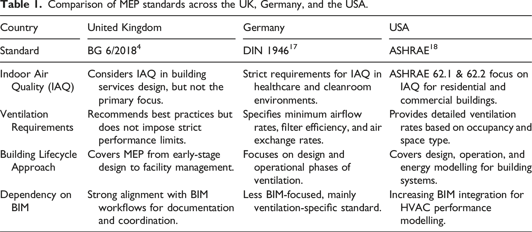
Although the fundamental principles of MEP schemas remain consistent—focusing on system logic, interconnectivity, and dependency modelling—their structure and content are shaped by national and international guidelines rather than a single global standard. In the United Kingdom, BG 6/2018: A Design Framework for Building Services, developed by BSRIA, 4 provides structured guidance on the organization of MEP documentation, defining deliverables and workflows throughout different project phases. Meanwhile, in Germany, DIN 1946 17 governs ventilation and indoor air quality, detailing requirements for system performance, hygiene, and thermal comfort. These frameworks, alongside others such as ASHRAE (USA), 18 BS EN (UK), 19 and PA 5601 20 (Norway), establish conventions for symbology, notation, and representation methods.17–20 However, their requirements differ, reflecting local construction practices, regulatory frameworks, and industry conventions. As a result, MEP schemas are not universally standardized, requiring adjustments when documentation is transferred between regions. 21
The knowledge represented by MEP schemas encapsulates a lot of information for various components. For example, an air handling unit (AHU) is not merely linked to a duct system - it carries assigned airflow parameters, pressure drop values, and dependencies on external conditions such as temperature and humidity levels. The explicit representation of these relationships ensures that designers can evaluate system efficiency, predict operational challenges, and resolve conflicts between disciplines.
Despite efforts to maintain consistency in the logical framework of MEP schemas, the absence of a unified global standard poses significant challenges, particularly for international projects. Differences in notation, calculation methodologies, and compliance requirements force engineers to modify, reinterpret, and adapt MEP documentation when transitioning between frameworks such as BG 6/2018 and DIN 1946. This inconsistency increases the effort required for coordination and verification, leading to inefficiencies and a higher risk of design errors. 22
Comparison of MEP standards across the UK, Germany, and the USA.
Interpretation of MEP schemas
The initial step in addressing issues related to the validation of MEP schema drawings is to comprehend and interpret their content. In recent years, several research studies have showcased different methods to tackle this issue. In the studies examined, a substantial majority depend on machine learning models, which have become essential for identifying MEP schematic components through deep learning symbol classification. Object detection frameworks such as Faster R-CNN, 24 YOLO, 25 and SSD 26 have demonstrated high accuracy in recognizing elements like pumps, valves, and electrical nodes. Faster R-CNN has been particularly effective in densely packed schematics, while YOLO offers real-time processing advantages, though it struggles with smaller symbols and overlapping components.27,28 Despite these advances, training models across different datasets remains a challenge due to variations in regional standards and company-specific symbology, limiting generalizability. 29 Furthermore, another challenge in obtaining a comprehensive understanding of data depicted by MEP schemas is the dependency and interconnection among them. This not only allows for the interpretation of the types of symbols present in a MEP schema but also clarifies how these symbols are interrelated. Understanding the functional relationships between system components is crucial, as these are primarily conveyed through connecting lines. Traditional edge detection methods such as Canny and the Hough transform have been used for extracting line structures, but they struggle with intersecting, curved, or broken lines common in complex schematics. 30 Recent deep learning models such as Holistically Nested Edge Detection (HED) and Line Segment Detection Networks (LSDNet) offer improved robustness, but challenges persist in distinguishing functional lines from non-essential graphical elements. 31
Semantics
The diversity of standards used for representing data in schematic drawings necessitates an efficient and flexible data structure capable of addressing this challenge. Moreover, the required data structure should not only accommodate schema representations but also integrate information from BIM models. In response to this need, recent research initiatives have focused on developing a wide range of ontologies32–39 that standardize current data exchange process, while ensuring knowledge interpretability for computer systems.40–43
Semantic web technology facilitates systematic associations between heterogeneous data sources by utilizing Uniform Resource Identifiers (URIs) as unique identifiers and ontologies as structured frameworks to describe information and its relationships. This technology is implemented using the Resource Description Framework (RDF). While no dedicated ontology currently exists for MEP schemas, several well-established ontologies have been developed to model both IFC-based data structures (e.g., ifcOWL) and the connectivity logic of MEP systems.32,33
One of the fundamental ontologies in AEC domain is the Building Topology Ontology (BOT), which provides a simplified representation of building structures. 37 Expanding upon this foundation, more specialized ontologies have been introduced to model MEP system connectivity in a more structured and interpretable manner. The Flow System Ontology (FSO) offers a coherent and extensible framework applicable to various building systems. 44 However, FSO ontology does not directly control or capture the dynamic state of fluid mass within a system. To address this limitation, the Tubes System Ontology (TSO) was introduced, enhancing FSO by explicitly modelling system states and fluid properties. 45
For a comprehensive and detailed representation of MEP systems, the Brick ontology provides an explicit classification of essential components, including equipment, sensors, data points, and their interrelations within buildings. 14 Additionally, the Smart Applications REFerence ontology (SAREF) has been developed to bridge the gap between BIM and IoT. 36 SAREF facilitates semantic interoperability by defining standardized models for energy, lighting, heating, and other building-related domains, making it particularly relevant for MEP applications that involve smart monitoring and automation.
This set of ontologies contributes to a more structured, interpretable, and machine-readable representation of MEP systems, enhancing data interoperability and facilitating advanced analysis across various applications. Moreover, it provides an efficient means to represent complex relationships in schematic drawings and BIM models, serving as a robust middleware for framework development. Importantly, the graph-based structure inherent in these semantic models supports SPARQL queries, enabling precise retrieval and integration of data by navigating the interconnected RDF triples that detail the relationships among building components, system states, and operational metrics.46,47
Framework
This section introduces a conceptual framework for cross-validating MEP schematic drawings against their corresponding BIM. The proposed approach utilizes Large Language Models and multimodal techniques to extract information from both schematics and BIM models, structuring this data within a semantic framework based on the Brick ontology. The methodology is designed to compare these semantic representations, enabling the identification of discrepancies and ensuring alignment between the schematic design and the detailed BIM model. Figure 1 provides an overview of the framework, with distinct colours used to highlight its sections and individual steps. Framework workflow overview.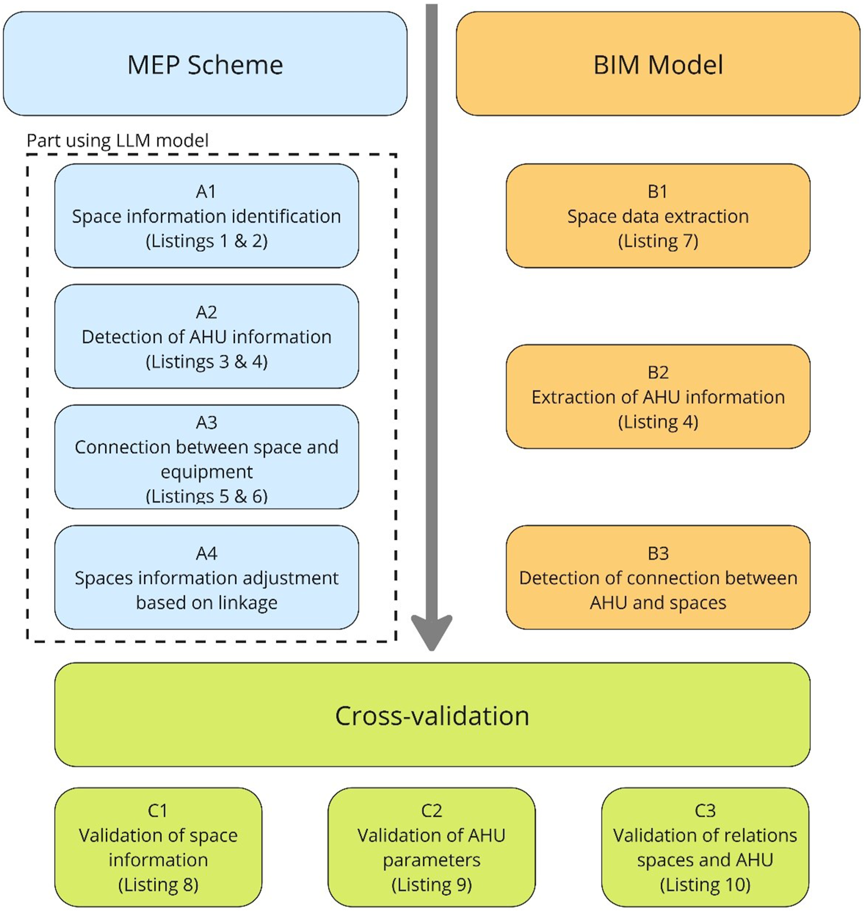
MEP schema processing
The first crucial step in this process is converting the knowledge embedded in MEP schematic drawings into a machine-interpretable format. This stage addresses key challenges such as visual symbol recognition, text extraction using OCR, and the interpretation of relationships. To achieve this, the study proposes a multimodal approach leveraging Large Language Models, such as GPT.
48
A key advantage of this solution is its ability to process both text and images, allowing for a more comprehensive interpretation of MEP schematics. Unlike traditional text-based models, this approach enables the processing of visual symbols, connections, and spatial relationships within the MEP schema. The process begins with inputting an MEP schematic as an image, typically in PNG, JPEG, or JPG format. An example of such a schematic, specifically from the ventilation domain, is shown in Figure 2. Example of MEP schema based on ventilation domain.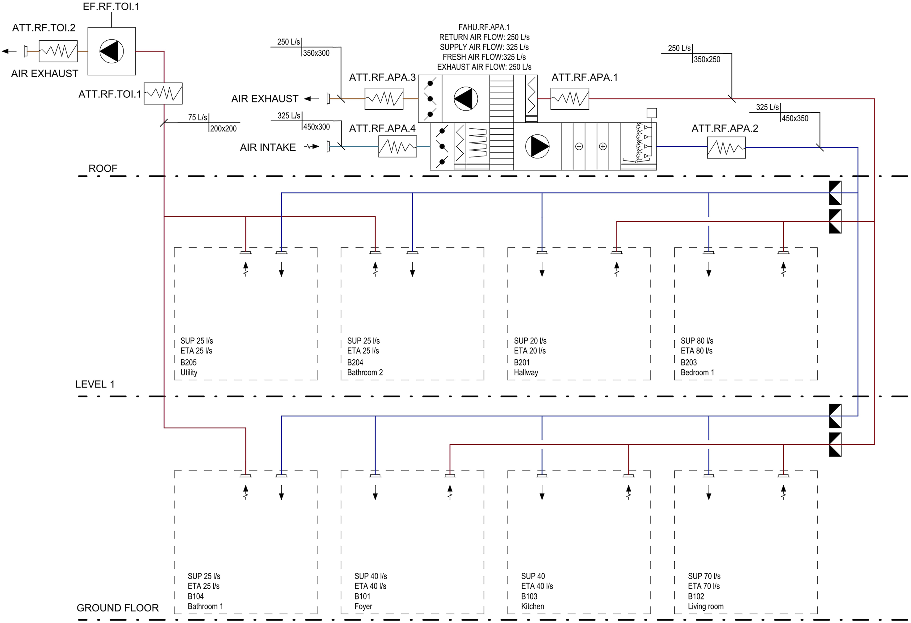
Step A1: Space information identification
The process begins by uploading the MEP schema, in the form of a figure, to the LLM model space for data extraction. Once uploaded, the first elements identified are the rooms associated with the system shown in the figure. The properties assigned to these rooms depend on the MEP system type and its domain. In heating and cooling systems, rooms are linked to parameters such as temperature setpoints or heat load requirements. In piping systems, relevant properties include pressure levels, fluid type, or flow rate constraints. For ventilation systems, the focus is on supply and return airflows, ensuring proper air distribution within each room.
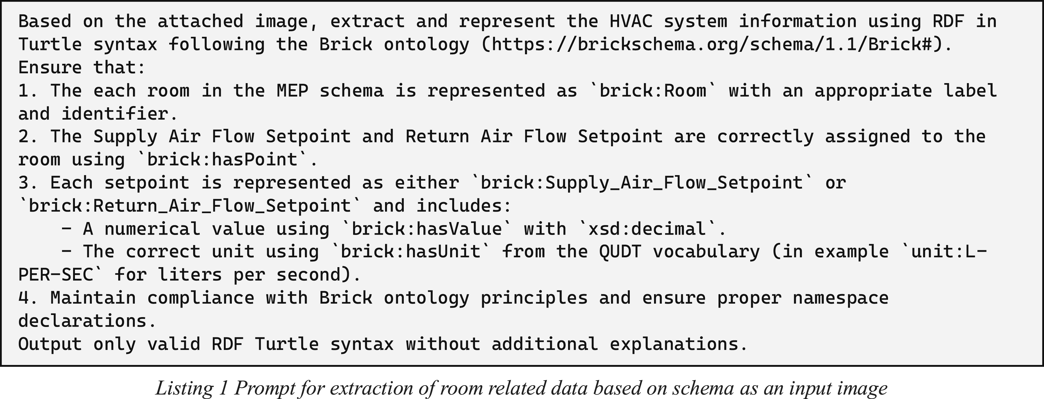
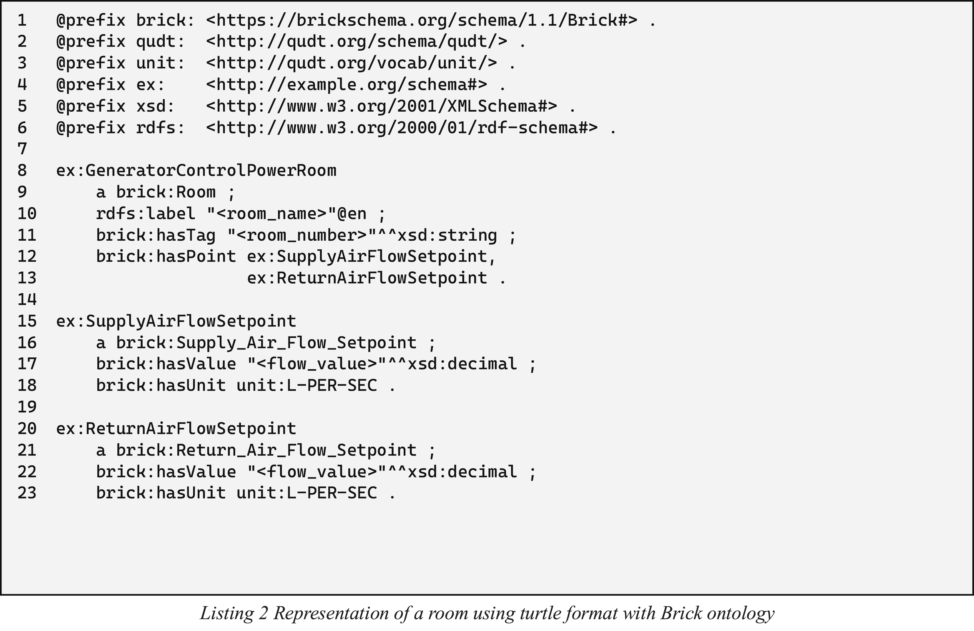
To standardize this representation, the BRICK ontology is applied. Each detected room is classified as a brick:Room, while expected supply and return airflow values are represented as designated setpoints following BRICK ontology principles. This structured approach ensures that the extracted information is both standardized and efficiently queryable.
Listing 2 provides an example prompt designed to extract structured RDF data from a schematic. This method can be used for querying a model through both chat-based interactions and API requests. The execution of this query produces results shown in Listing 2, which describes a room with a designated identifier representing its number. Additionally, it correctly assigns the supply and return airflow setpoints, including their corresponding units.
Step A2: Detection of AHU information
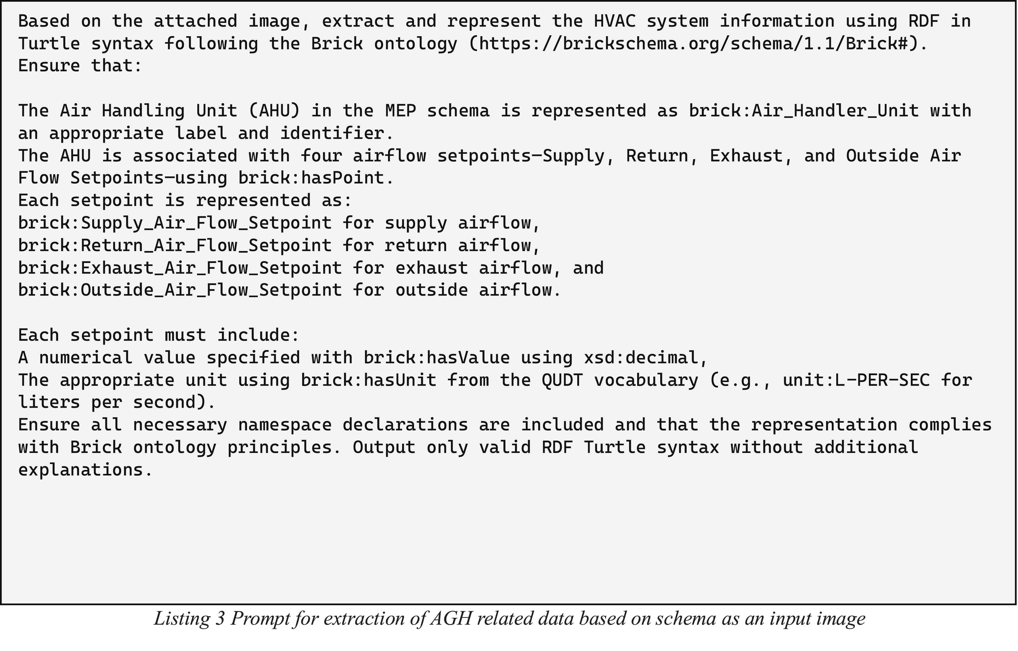
After identifying the rooms and their required airflow setpoints, the next step is to detect the components responsible for delivering these flows. Air Handling Units serve as central elements of the ventilation system, ensuring the necessary airflow by processing and distributing air across different zones. Their role extends beyond simple air movement—they regulate four interconnected airflow streams: outside air intake, supply air delivery, return air recirculation, and exhaust air expulsion. AHUs function by drawing in outside air, filtering and conditioning it before supplying it to designated rooms. Simultaneously, they manage return air, either recirculating it back into the system or expelling it as exhaust air. The information related to AHU are captures using Listing 3. By capturing these airflow relationships, the structured representation in RDF ensures interoperability, enabling effective querying, reasoning, and integration with building information models.
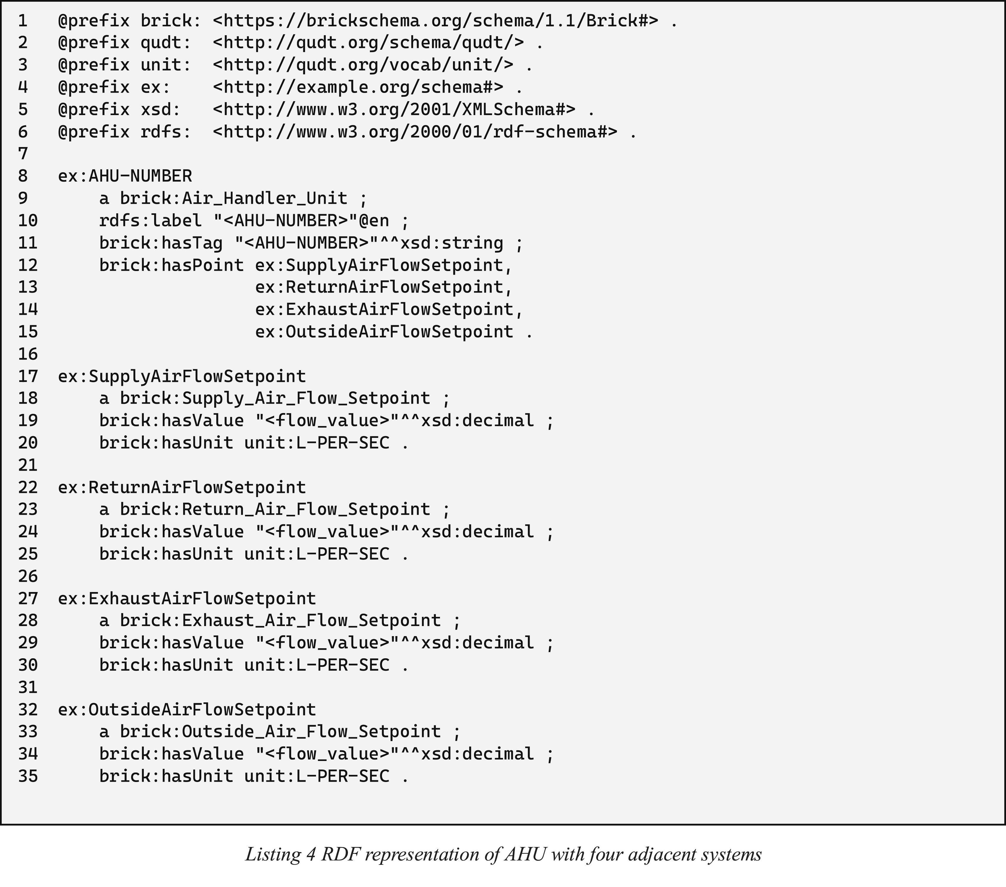
Given that AHUs integrate these four airflow systems, their operational parameters can be represented in RDF, as shown in Listing 4. This listing encodes an AHU instance (AHU-NUMBER) with its respective setpoints for supply, return, exhaust, and outside airflow. The representation adheres to Brick Schema principles, ensuring a standardized and machine-readable format that facilitates data-driven ventilation system management.
Step A3: Connection between space and equipment
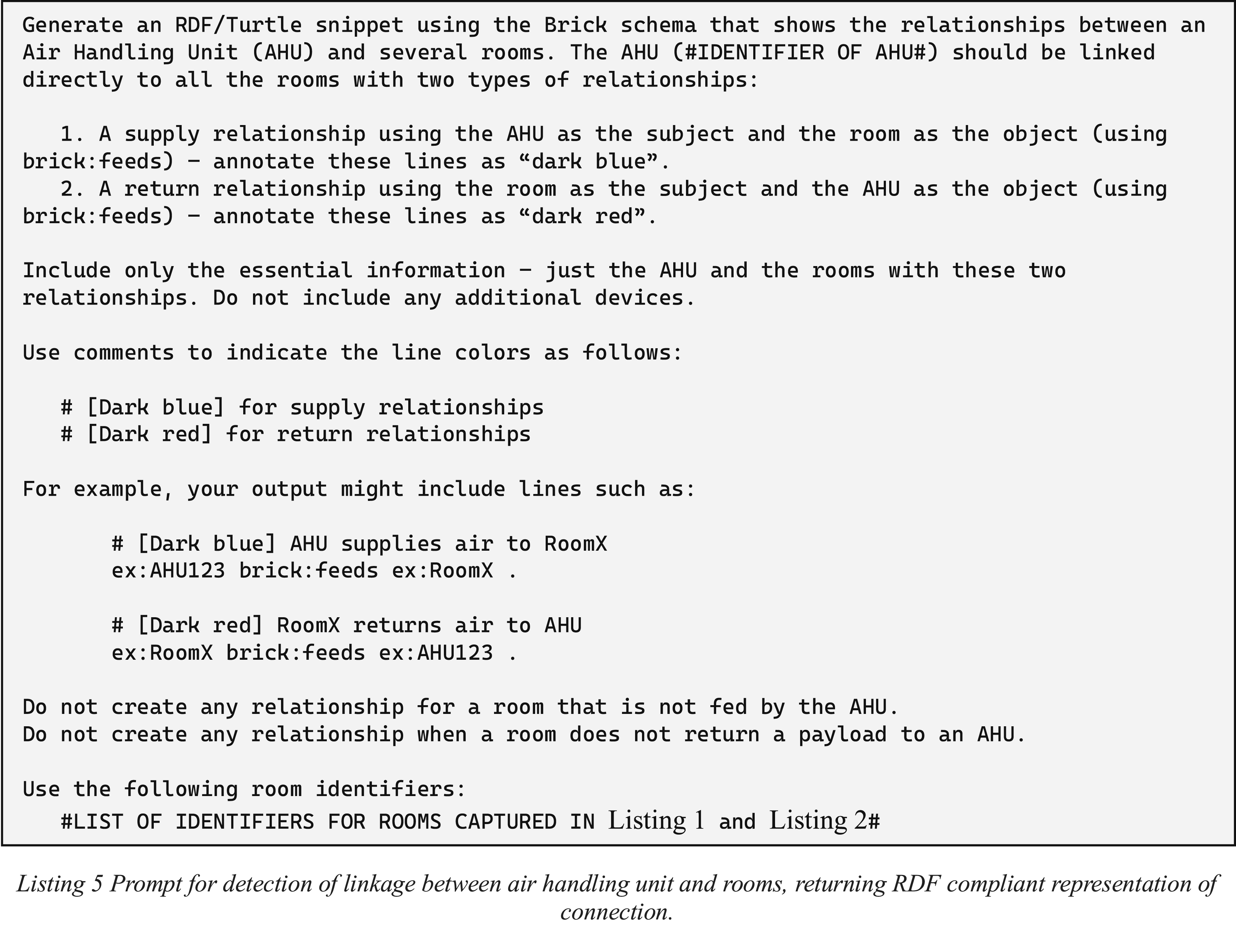
After identifying rooms and assigning their respective supply and return requirements, the next step involves investigating the connections between previously identified room elements (step A1) and the AHU (step A2). In the MEP schemas, these connections are represented by lines symbolizing logical relationships between system components. The primary objective at this stage is to extract and represent these logical interdependencies according to brick ontology principles. Specifically, it requires identifying and capturing the connectivity details shown in the schematic, clearly indicating which rooms are linked to the AHU.
Listing 5 presents the LLM prompt designed to capture these relationships, utilizing information previously gathered in steps A1 and A2. It builds upon already recognized system components and emphasizes detecting their linkages. In this prompt, supply air lines are highlighted in dark blue, while return air lines are indicated in dark red.
Step A4: Spaces information adjustment based on linkage
As presented in Step A1, the workflow assumes that rooms receive air from an AHU and return the air to the same AHU, using a SupplyAirFlowSetpoint and a ReturnAirFlowSetpoint. However, HVAC systems in certain spaces, such as toilets, kitchens, and other specialized areas, do not follow this standard model. In these spaces, air is typically exhausted directly outside due to contamination or specialized treatment requirements. Figure 2 provides an example of this scenario for bathrooms.
After applying Step A3 and identifying the ontology-based relationships between the AHU and the rooms, it becomes necessary to modify the original room representation proposed in Listing 2. This adjustment involves changing the class for ex:ReturnAirFlowSetpoint from brick:ReturnAirFlowSetpoint to brick:ExhaustAirFlowSetpoint in rooms where air is exhausted externally. Similarly, for rooms that do not receive air directly from the AHU but from outside sources, the class for ex:SupplyAirFlowSetpoint must be modified from brick:SupplyAirFlowSetpoint to brick:Outside_Air_Flow_Setpoint.
BIM model data extraction
After successfully extracting relational data from MEP schema, the next phase focuses on converting the BIM model into an RDF-compatible Turtle format. 49 This transformation is essential for linking visual design data with semantic representations, thereby facilitating advanced reasoning, enhanced querying, and robust cross-validation of system interconnectivity. The current methodology employs Autodesk Revit—a leading BIM modelling software among AEC professionals. 50 The initial task is to establish a reliable method for extracting component data and storing it in RDF format. However, the literature review reveals a lack of any existing Revit-to-RDF exporter that supports BRICK ontologies. Instead of developing a custom plugin using the Revit API, the framework currently relies on Dynamo, Revit’s visual programming interface, to perform the extraction. 51
Step B1: Space data extraction
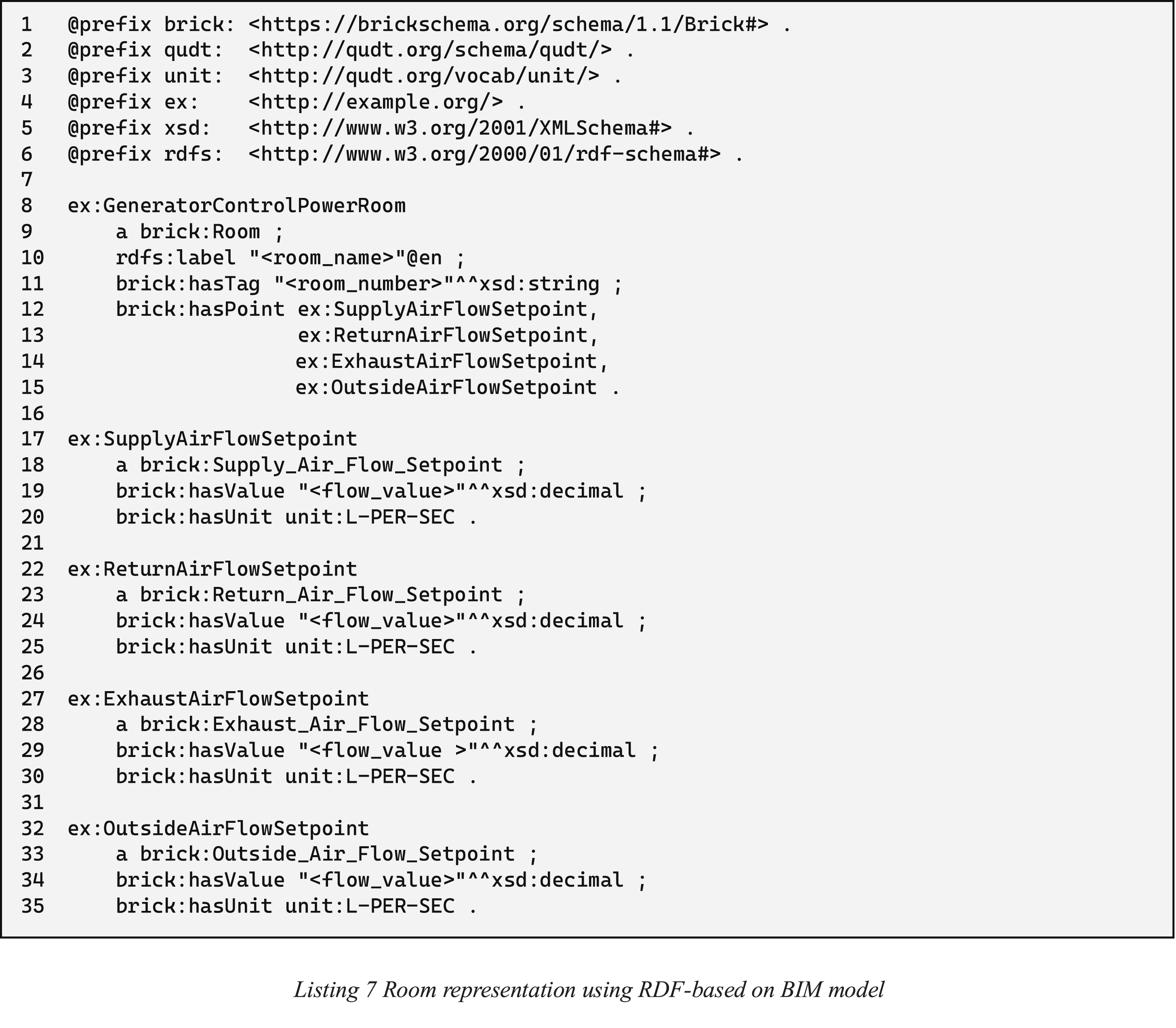
Following a similar approach to that used for MEP schema drawings, the first step in BIM model extraction is to identify and capture data associated with individual rooms. In the BIM environment, each space is defined by physical elements—such as air terminals, sensors, and controllers—that manage the delivery of air, water, or heat, as well as their return to the corresponding equipment. A key advantage of using BIM data is that room attributes are directly available without the need for additional inferential reasoning, unlike the process required for MEP schemas. Information concerning supply, return, exhaust, and outdoor air is inherently assigned to each space through these physical elements. Based on the flow values specified by BIM modelers or designers, each room aggregates this information into a comprehensive set of parameters that reflect its overall performance requirements. This direct extraction not only simplifies the process but also minimizes errors that could arise from more complex connectivity analyses between rooms and AHUs, as exemplified in Listing 7.
Step B2: Extraction of AHU information
The next step involves extracting detailed information related to AHUs. In contrast to room data extraction, capturing AHU details requires a different strategy for associating flow parameters. Relying on a single global flow parameter for ducts or fittings is correct. But in case of AHUs it might lead to the erroneous assumption that supply and return airflows are always identical.
52
To address this challenge, the methodology avoids a monolithic “Flow” parameter and instead uses individual connectors, similar to IfcPorts, to capture distinct airflow streams. As illustrated in, a typical AHU component is equipped with four connectors, each of which is assigned parameters that define its specific role—whether it is handling supply, return, exhaust, or outside air. Additionally, when an AHU is integrated into a project, each connector is allocated a calculated flow corresponding to its connection with end components in the rooms. This refined, connector-level approach allows for a more accurate and detailed representation of the AHU’s performance. The extracted data is then structured into RDF/Turtle format in a way that mirrors the representation shown in Listing 4, ensuring that the nuances of AHU operation are preserved for subsequent analysis and validation (Figure 3). Sample AHU component in Revit software.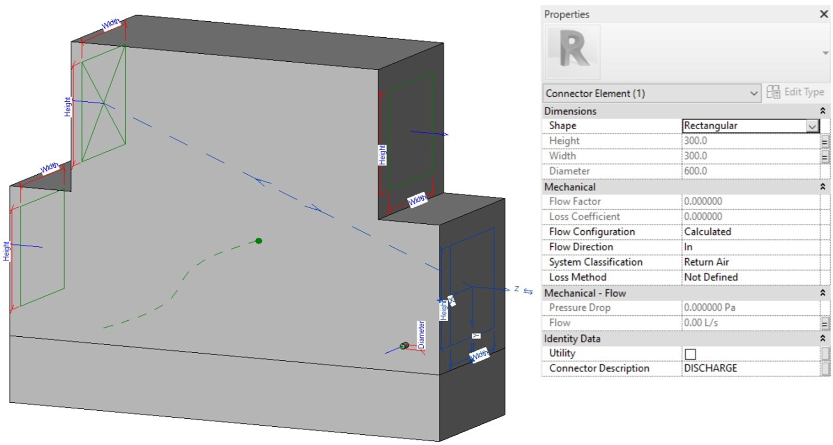
Step B3: Detection of connection between AHU and spaces
The final stage of data extraction for a BIM model involves detecting the connectivity between components. Unlike Step A3, where links between an Air Handling Unit (AHU) and spaces are represented by abstract logical connections, this stage focuses on physical entities such as ducts, pipes, and their respective fittings. These elements are interconnected through connectors, each providing essential information, including flow direction (in/out), associated connectors, and the hosting element. Figure 4 illustrates an example of a fitting element used to connect two segments within the system. The geometry of this component is defined by its adjacent connected elements, specifically in terms of width and height. Additionally, it features two visible connectors, each linked to a segment, facilitating the propagation of flow information to the next element in the system. Example of intermediate component connecting AHU and Space, based on example of fitting element.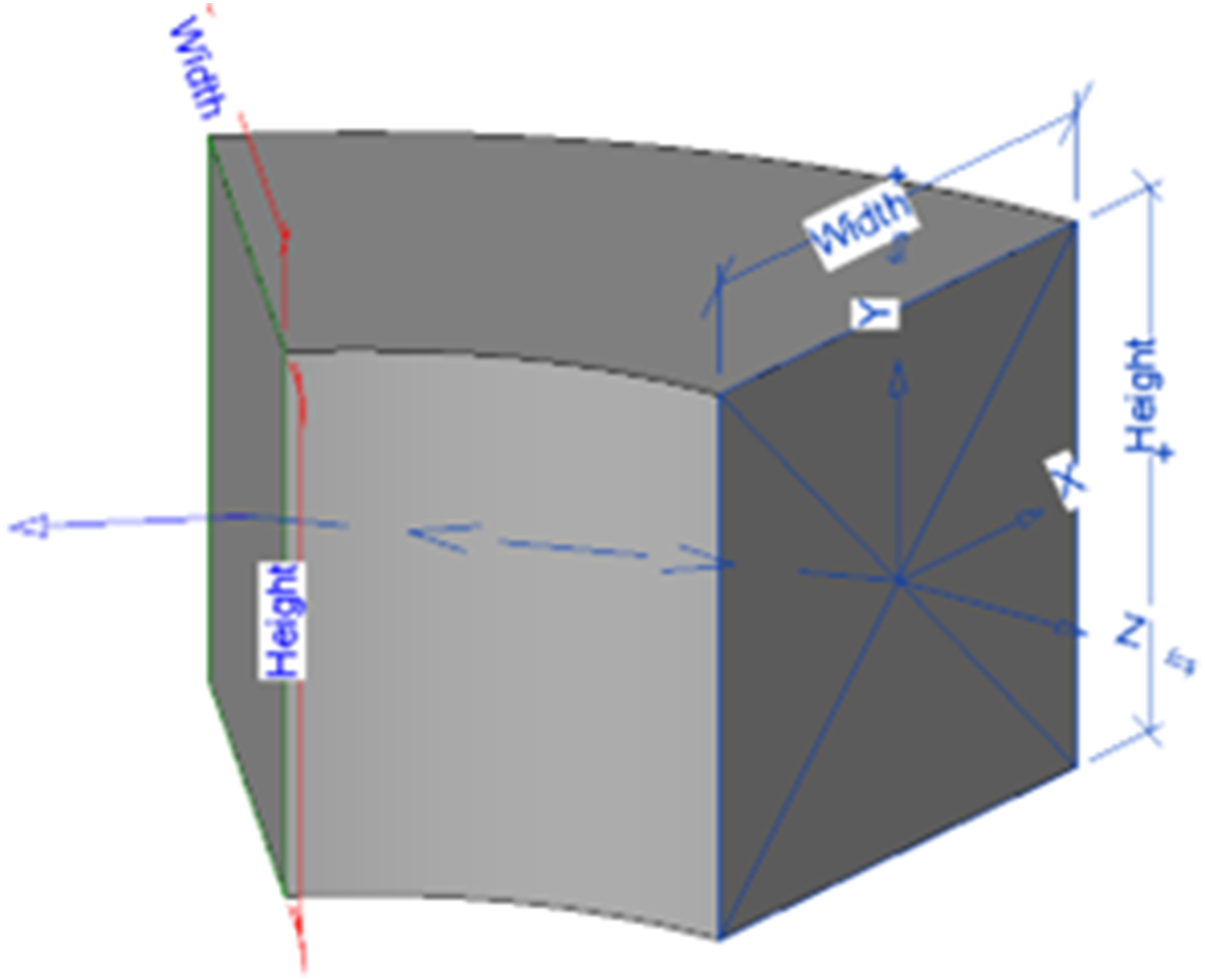
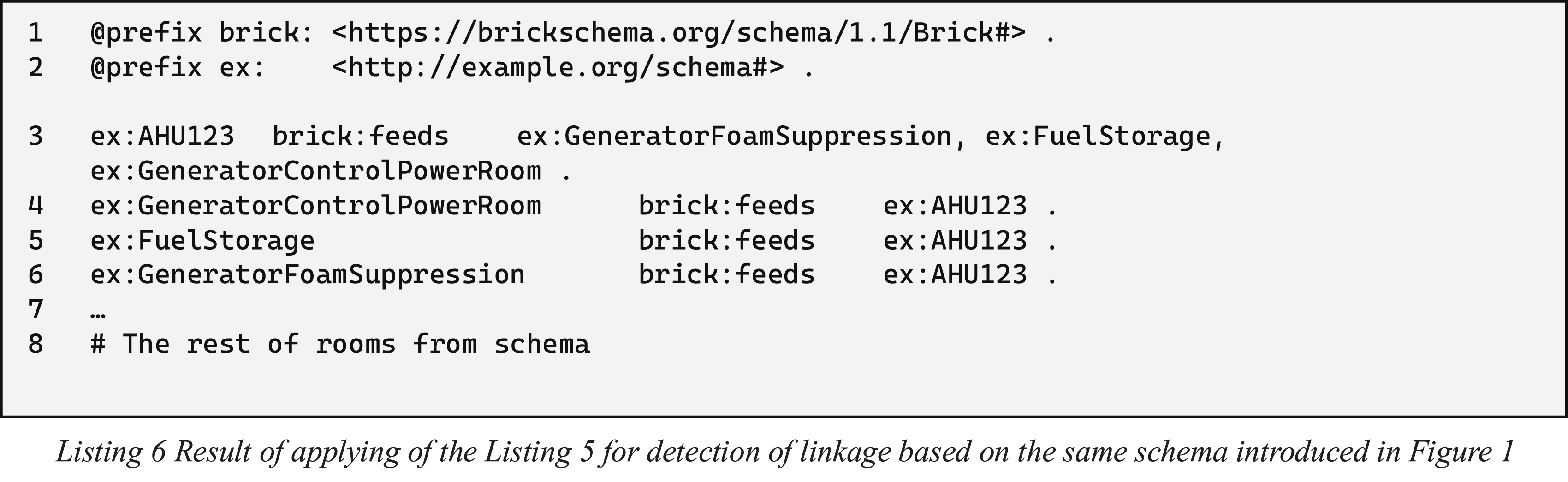
This structured representation significantly simplifies the process of identifying logical chains of connections compared to the interpretation of physical drawings. However, depending on the design stage and model complexity, such connection paths may comprise hundreds of individual components. To mitigate this complexity, the proposed methodology introduces a simplified representation that preserves the essential data required for reasoning. This approach ensures consistency with the information conveyed in MEP schematic drawings while maintaining the same RDF structure as presented in Listing 6.
Cross-validation
At the final stage, the framework ensures that the MEP schematic drawings and the corresponding BIM model are coherent through cross-validation process. This process is carried out in three interrelated parts, focusing sequentially on validating room details, AHU details, and the connections between them. By systematically comparing the semantic representations derived from the schema with the physical data extracted from the BIM model, discrepancies can be identified early, thus preventing rework during later project phases.
Step C1: Validation of space information
The first part of the cross-validation process involves a detailed examination of room details. In both the MEP schema and the BIM model, rooms are the fundamental units where airflow parameters and spatial configurations are defined. In the schematic, room information is abstractly represented using semantic annotations such as labels, identifiers, and associated airflow setpoints (for example, supply and return air flow). The BIM model, on the other hand, captures room data as physical spaces with precise measurements information. A SPARQL query can be constructed to extract room attributes from the RDF representations, allowing for a direct comparison of labels, numerical values, and unit specifications. Listing 8 presents a SPARQL query used for the extraction of data from a graph form to a single data row representing the room URL, the room label and all supply and return values.
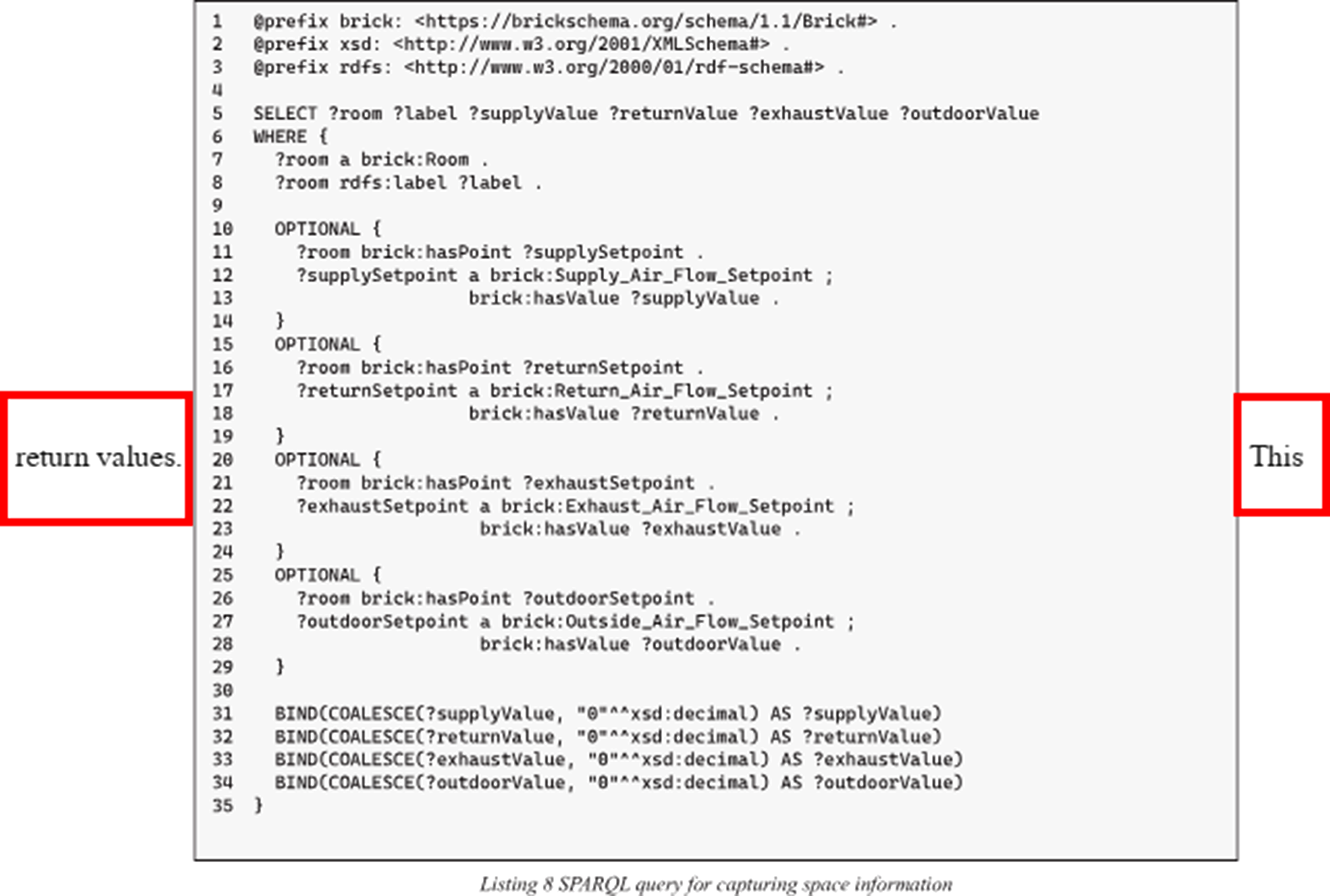
This query extracts essential room information from RDF datasets that use the Brick ontology. It selects each room’s unique identifier, its human-readable label, and the airflow values for the supply and return setpoints. The query uses the COALESCE function to ensure that if any airflow value is missing, it returns a default value of 0. This feature guarantees that for every room the output structure is the same, even if some data points are missing.
By using the room identifier or label as a key, the two datasets can be directly compared. The supply and return airflow values from the schematic should match the values in the BIM model. Minor differences might occur because of rounding or measurement tolerances, but any significant discrepancies could indicate errors in data extraction or integration.
Step C2: Validation of AHU parameters
The second part of the validation focuses on the Air Handling Unit (AHU) details. AHUs serve as the central node in HVAC systems, and any deviation in their representation can have significant implications on the entire system’s operational efficiency. In the MEP schema, AHUs are depicted through multiple setpoints corresponding to various airflow types, including supply, return, exhaust, and outside air. In contrast, the BIM model captures AHU details by representing the physical connectors and operational parameters in a detailed manner. To cross-validate these components, a dedicated SPARQL query can be employed to extract and compare the airflow parameters associated with each AHU using a similar query as one presented in Listing 8. The query has to be slightly modified to ensure that extracted object information is related to AHU component, not for room, resulting in modifications of the query in lines 7 and 8 in contract to space-oriented query as presented in Listing 9.
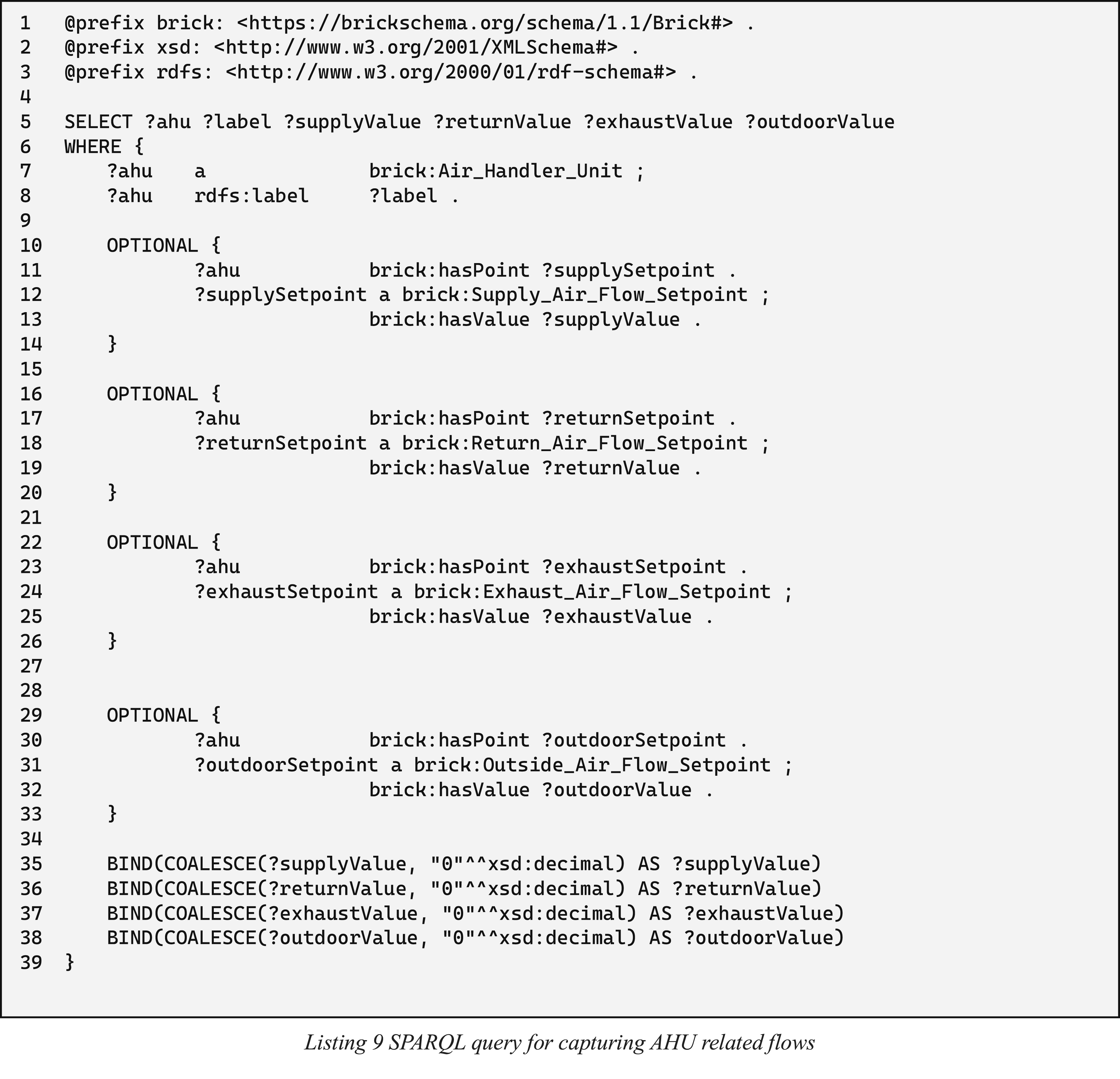
This query is designed to extract the comprehensive set of airflow values for each AHU. By comparing these values across the two representations, it becomes efficient to validate that the schematic assumptions regarding air distribution and processing are accurately implemented in the BIM model. Differences in setpoint values or missing airflow components may indicate that either the MEP schema has oversimplified certain aspects or the BIM extraction process has failed to capture all relevant details or BIM model is not coherent with initial assumptions during a design.
Step C3: Validation of relations spaces and AHU
The final part of the cross-validation process examines the connections between spaces and AHU. In the schematic representation, connections are typically illustrated as abstract lines denoting logical relationships between components, whereas in the BIM model, these connections contain physical elements such as ducts, pipes, and fittings. Validating these interconnections is essential to confirm that the designed pathways are maintained in the BIM model. Presented in Listing 10 SPARQL query is formulated to capture the relations between AHU and relevant spaces.
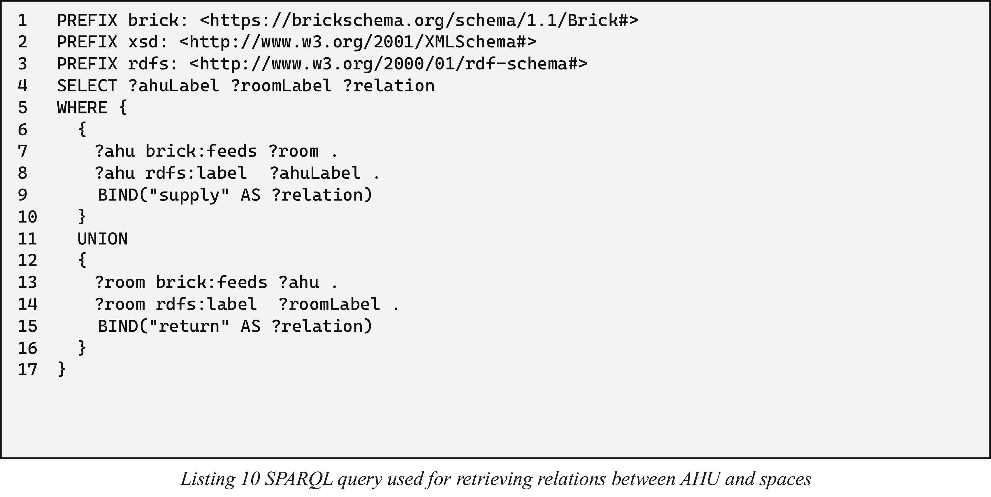
By running this query on both graphs, representing MEP schema and BIM model, the results all relations between spaces fed by AHU and all spaces which return payload to AHU. This validation process identifies which whether every logical connection is appropriately represented in the physical model. For example, if a space that is supposed to receive supply air from a specific AHU in the schematic does not have a corresponding connection in the BIM model, this discrepancy is highlighted. Such mismatches reveal issues in the data extraction process or indicate that the schematic did not fully capture the complexity of the physical system. This stage is crucial for confirming that the designed flow paths are maintained, and it supports further analysis related to energy efficiency and safety compliance.
Through the comprehensive cross-validation of room details, AHU parameters, and the interconnecting relationships, this section of the framework ensures that any inconsistencies between the MEP schematic and the BIM model are quick and efficient for being identifies and highlighted for a user which can easily address such discrepancy, by updating initial schema of adjusting a BIM model for initial assumptions. This process enhances the overall reliability and performance of the building system design, reducing required workload among stakeholders and reducing the risk of costly errors during construction and operation.
Discussion
This study presents a conceptual framework designed to cross-validate MEP schematic drawings with their corresponding BIM models. By leveraging semantic representations and employing advanced AI-driven tools, the framework establishes a robust method for comparing abstract design assumptions with detailed physical models. The integration of large language models with semantic web technologies allows for the extraction, transformation, and validation of complex relational data from both schematics and BIM environments. In doing so, the framework not only facilitates early detection of discrepancies—such as mismatches in airflow values, connectivity errors, or incomplete component representations—but also significantly reduces the risk of costly rework during later construction stages. The methodology underscores the critical role of semantic interoperability in modern AEC projects, where diverse data formats and varying levels of detail often impede efficient integration and validation processes.
Data structure
Data structure plays a critical role in the framework. To enable flexibility and provide machine interpretability, semantic graph databases were leveraged. They were selected because of several arguments.
The first reason for using a semantic structure is that it provides an efficient data format that is both machine-readable and machine-interpretable. This contrasts with a traditional Structured Query Language (SQL) approach, where all relationships between tables must be predefined, which make it flexible and easily adaptable for any scenario. Despite the existence of several ontologies - such as FSO, TSO, ifcOWL, or BOT - the Brick ontology appears to be the best choice for this assignment.14,33,37,44,45 Its wide range of classes allows for a clear classification of components and a precise description of their roles in the system. As discussed in Sections 3.1 and 3.2, the flow representation goes beyond a simple value and includes detailed information about the system function to which it is related. In contrast, the FSO ontology does not include information about assignable setpoints and component related information is limited to fso:Component class. Better alternative is TSO, which has tso:State class, which can be used as an equivalent to brick:Setpoint, but it does not provide as sufficient amount of subclasses to support a detailed and reliable system description to which it related to.
A second argument for choosing the Brick ontology over other systems is its potential for future extension. The current framework focuses on main components such as AHUs and spaces, but there are several other components crucial to system operation. An example is the inclusion of dampers, actuators, and pressure regulators. It is important that when the data is translated into a graph structure, this information is accurately represented and can be easily adjusted based on national requirements or organizational preferences. This flexibility makes the Brick ontology the best choice for MEP schema representation and addresses RQ1.
The structure and flexibility of the selected ontology support the extension and integration of various types of information. Brick ontology offers a modular design that simplifies the incorporation of additional elements and relationships. It allows for a dynamic approach to data modelling, removing the need for rigid pre-definition of table relationships. This adaptability ensures that future enhancements - such as integrating energy analysis, sensor data, and real-time monitoring can be efficiently integrated. Its clear classification system simplifies maintenance and supports scalability, while also promoting interoperability between different platforms. These factors make Brick ontology a robust solution for storing both MEP schemas and BIM models, effectively addressing RQ2.
Benefits using a cross-validation tool
The early-stage conceptual framework introduced in this study is designed specifically with the requirements of the ventilation domain in mind, yet it also offers advantages for a broader range of users throughout the design process. Primarily, the framework supports the close collaboration between BIM modelers and designers. While designers are responsible for establishing system performance criteria, ensuring design compliance, and setting initial assumptions, BIM modelers must translate these requirements into a detailed BIM model. In practice, discrepancies often arise between the initial schematic assumptions and the final BIM representation, mainly due to the lack of an efficient tool for rapid and reliable cross-validation. The proposed framework directly addresses this gap by providing a structured method for comparing schematic and BIM data, thereby reducing potential inconsistencies.
In addition to benefiting the primary design teams, the framework is also valuable for facility managers and quality assurance professionals who are involved during the post-design validation and handover phases. For projects with extensive documentation, where dozens or even hundreds of schemas and system components require verification, this approach streamlines the process and minimizes the risk of errors. By automating significant parts of the cross-validation process, the framework not only cuts down on manual workload but also enhances the overall reliability and accuracy of the building’s design and operational data. This, in turn, can lead to improved project outcomes, reduced rework, and increased confidence in the final construction addressing the RQ3.
Limitations
IFC
Despite the promising observations, several significant limitations emerged during initial testing. The first issue concerns the reliance on native software rather than an open format such as IFC. While IFC files can be converted using existing tools—for example, the IFCtoRDF by Pauwels et al. 53 for conversion of IFC to ifcOWL or the or the approach by Oraskari et al. 54 that employs a suite of Linked Building Data ontologies -the main challenge lies in the way IFC represents components. Although IfcSpaces are modelled with sufficient detail, the information associated with IfcAirToAirHeatRecovery components remains problematic.55,56 Specifically, an AHU may have several IfcDistributionPorts with different flow values, yet the current IFC schema does not mandate a flow property for each port, resulting in only one flow parameter for the entire unit rather than individual values for each port. 57 This limitation is a key reason for basing the framework on native software rather than an open standard.
Image resolution in LLM processing
Another group of limitations relates to the image processing capabilities of the GPT engine. The maximum allowed resolution for images processed by the OpenAI engine is 768 × 2000 pixels. 58 While this is adequate for analysing text samples or information pertaining to a single space, it falls short for complex MEP schemas. As a result, although the framework can correctly detect the connections between spaces and the AHU, it may confuse detailed data—such as flow values—due to the visual similarity between digits like 0, 8, and 6. Additionally, the tokenization of large images incurs a cost of a few cents per request. Although this cost is manageable on a small scale, repeated processing for multiple systems in a complex building can accumulate to a significant expense. For instance, in our tests with the sample MEP schema from Figure 2, processing the image 88 times using the GPT-4 model resulted in a cost of $1.97; this cost can vary depending on the model and image size, potentially leading to higher expenses per input and output token.
Schema standardization
The final framework limitation is lack of MEP schema standardization among AEC professionals. The diverse array of national and regional standards related to MEP schemas introduces substantial complexity into the extraction, validation, and integration processes. The necessity of adapting the extraction prompts to address differences between standards such as BG 6/2018 (UK), DIN 1946 (Germany), ASHRAE (USA), and other international guidelines adds complexity and increases the time required for developing reliable, fully automated extraction method.4,17,18 Furthermore, the variability in representation styles—including the usage of different symbols, flow annotations, and line conventions—can lead to inaccuracies or incomplete data extraction, thereby reducing the overall reliability of automated validation outcomes.
Conclusion
Summary
This study introduced a conceptual framework for validating the consistency between MEP schematic drawings and their corresponding BIM models using semantic representations. The framework leverages AI-driven tools, specifically LLMs, to extract structured knowledge from MEP schematics and BIM models. By translating this information into a semantic format based on the Brick ontology, the approach enables automated cross-validation, improving coordination, accuracy, and efficiency in the design and construction workflow.
Through a systematic methodology, the framework facilitates the detection of inconsistencies between schematic assumptions and BIM representations at an early stage, reducing the risk of costly design errors and rework. The structured data representation enables flexible querying and reasoning, making it easier to verify system connectivity, airflow parameters, and compliance with engineering constraints. This not only enhances collaboration between design teams and BIM modelers but also supports facility management by ensuring that documented assumptions remain consistent throughout a building’s lifecycle.
Despite its advantages, the framework faces certain limitations, such as the reliance on proprietary BIM software for data extraction and the constraints imposed by current image processing techniques. Additionally, the diversity of drafting standards and regulatory differences presents challenges in achieving full automation.
Finally, the study contributes to the ongoing digital transformation in the AEC industry by providing an efficient, automated approach for validating MEP schematics against BIM models. By integrating semantic web technologies with AI-based analysis, it paves the way for more reliable, interoperable, and data-driven design processes, ultimately improving project coordination and decision-making.
Future work
Future work will focus on the development of a dedicated plugin that automates the proposed workflow, ensuring its practical applicability while addressing current limitations related to data extraction and validation. Expanding the framework to cover additional MEP domains such as electrical and plumbing systems will enhance its versatility and allow for a more comprehensive validation process across various building services. Further improvements should refine AI-driven recognition methods by optimizing prompt engineering for schema interpretation and exploring alternative large language models to assess their effectiveness in handling diverse schematic representations. Efforts should also be directed toward enhancing the interoperability of the framework with open standards such as IFC, reducing reliance on proprietary BIM software and facilitating broader industry adoption. Given the constraints imposed by current image processing capabilities, future studies should investigate alternative approaches to improve symbol detection and text extraction accuracy in complex schematics, particularly when dealing with diverse drafting conventions. Additionally, the integration of real-world case studies and industry feedback will be essential in assessing the robustness of the framework and identifying potential enhancements. Addressing the challenges posed by national and organizational drafting standards will be crucial in ensuring that the methodology remains adaptable across different regulatory environments. Lastly, further exploration of semantic data structuring will be necessary to support more advanced reasoning capabilities, including the validation of system performance criteria and compliance with engineering constraints. These advancements will contribute to the refinement of automated cross-validation techniques, ultimately improving the efficiency and reliability of MEP-BIM coordination in practice.
Footnotes
Author contributions
Wojciech Teclaw: conceptualisation, investigation, methodology, writing original draft and writing review & editing. Marcin Luczkowski: conceptualisation, methodology, writing review & editing. Nathalie Labonnote: project administration, supervision and writing review & editing. Eilif Hjelseth: project administration, supervision.
Declaration of conflicting interests
The author(s) declared no potential conflicts of interest with respect to the research, authorship, and/or publication of this article.
Funding
The author(s) received no financial support for the research, authorship, and/or publication of this article.
Declaration of Generative AI and AI-assisted technologies in the writing process
In developing this manuscript, ChatGPT, a generative AI language model, was utilised to improve the readability and grammar syntax.