
Abstract
Robotic Clay Printing (RCP) offers opportunities in sustainable architectural applications. This paper presents a framework to integrate locally sourced earth-based materials with robotic fabrication techniques while enhancing designer's control over the process. The methodology involves two key steps: first, refining critical 3DP (3DP) control parameters to develop an informed toolpath algorithm. This algorithm grants designers’ direct control over factors like layer height and extrusion speed, enabling customization and ensuring structural integrity. Second, the framework is applied to design and RCP of an interlocking modular wall component system. Evaluation encompasses the impact of 3DP control parameters, informed toolpath planning, RCP performance, and assembly possibilities.
Keywords
Introduction
3DP is an innovative additive manufacturing technique known for its layer-by-layer material deposition process, which has revolutionized manufacturing and expanded material utilization possibilities in various industries. 1 In construction, substantial research efforts are dedicated to exploring and refining 3DP materials and processes, offering benefits such as reduced waste, elimination of the need for molds or formwork, and enhanced design flexibility. 2 It also reduces construction time for non-standard structures and reevaluates labor safety in challenging environments.3,4 Research in 3DP for architectural applications can be categorized by technique, material, scale of application, and form studies.
Early architectural applications of 3DP predominantly focused on cement-based materials, with three notable large-scale Additive Manufacturing (AM) processes—Contour Crafting, 5 D-Shape (Monolite), 6 and Concrete Printing 7 —successfully producing large-scale components suitable for construction and architecture.2,8 Contour Crafting automates full-scale wall construction using cement-based paste deposition. However, it has limitations regarding design freedom due to material properties and overhang constraints. Similarly, Concrete Printing faces design constraints without support material or framework. In contrast, D-Shape employs a powder deposition technique with binder hardening, offering more design freedom but with scalability limitations due to required formwork. Current 3DP applications in architecture range from on-site house construction to building component production with diverse material compositions.2,9–11
Despite extensive research on cement-based materials in AM, earth-based materials have received relatively less attention. Earth-based materials have a rich history in vernacular construction, driven by their accessibility, adaptability, thermal properties, and structural capacity. 12 This study explores the potential of locally sourced earth-based materials as sustainable alternatives to cement-based materials when combined with modern fabrication techniques. Current 3DP research involving clay as a building material primarily focuses on on-site applications of locally sourced materials,13–17 various extrusion systems,18–21 and material mixtures.22,23 For instance, TerraPerfoma utilizes an industrial robot to 3D print prefabricated modular terracotta components. 24 The Pylos project employed crane WASP technology, soil, rice straw, rice husk, and hydraulic lime to construct an on-site house.25,26 On another scale, the University of Hong Kong (HKU) researchers presented a 3DP method for coral restoration using 3D-printed artificial “reef tiles” to support coral growth in Hong Kong waters. 27
3DP offers design freedom, enabling the creation of intricate and complex shapes that were previously challenging or unattainable through traditional manufacturing methods. This technology, while not without limitations, enhances designers control over a design's form, curves, and details, eliminating the need for complex molds or tooling. The key parameters governing 3DP, primarily influenced by material and extruder properties, play a crucial role in shaping the design process. However, the comprehensive exploration of these parameters, their interplay with complex geometries and material-tool interactions, remains a relatively underexplored area in existing research.28–31
Advanced parametric design software, in combination with extruder and material constraints, offers designers newfound freedom and precise control over their creations. This flexibility allows for the customization of structures to meet specific environmental and structural demands, such as adjusting material deposition speed to enhance durability or performance. Furthermore, the careful consideration of 3DP parameters, including infill properties, overhang limits, layer thickness, and material deposition, provides valuable insights for production optimization.
This study focuses on understanding the holistic nature of 3DP, where each input directly impacts the outcome. It specifically concentrates on variable parameters as design inputs, encompassing aspects such as the behavior of viscous materials, the interaction between the designed tool, selected material, and geometric constraints. To accomplish this, material testing and tool-building processes were conducted concurrently, leading to the development of an informed toolpath algorithm that governs essential 3DP parameters.
The developed informed toolpath algorithm offers interactivity and adaptability, allowing users to control and visualize 3DP parameters and generate machine codes based on not only predefined optimization criteria but also design-specific considerations. The primary goal of employing this algorithm is to integrate tool and material properties as design parameters during the early design phase. The primary aim for employing the developed algorithm is to incorporate tool and material properties as design factors, together with other form-finding studies, in the initial design stage.
The feasibility of this framework and the informed toolpath algorithm is assessed through the RCP of a modular, interlocking component system. Evaluation criteria cover surface quality, overhang limits, a comparison between the provided design and the printed component, overall shrinkage post-firing, and printing time. While clay-based materials and mixtures are employed in the final application, it is important to note that the proposed framework and algorithm for informed toolpaths can be adapted for use with other paste-like materials and open-source extruders.
Methodological framework
The methodology for this study was conducted in two distinct phases, as illustrated in Figure 1. The first phase involved rigorous material and tool tests to establish crucial 3DP control parameters, including shell thickness, layer height, deposition speed, and infill design properties for various geometric inputs. These findings informed the development of an adaptive toolpath algorithm, specifically tailored to the identified 3DP parameters, creating a robust framework for architectural-scale, off-site units using RCP technology. Diagram of the methodological framework for the 3D Clay Printing process.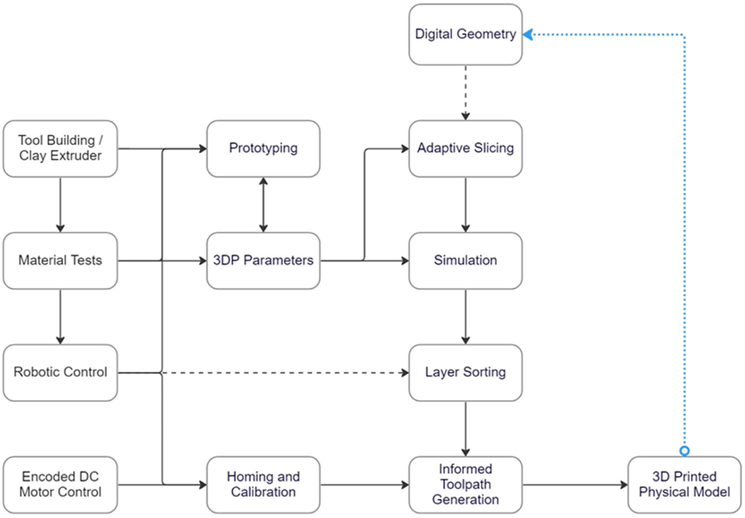
In the material testing stage, different locally sourced clay mixtures were examined, including red ceramic clay, white ceramic clay, granulated ceramic clay, and a granulated ceramic clay/sodium alginate mixture. Five specific material mixtures (C1 to C5) were tested, each with varying compositions and water content. C1: Material mixture consisting of red ceramic clay body from Bilecik, Türkiye with an unknown composition, fired clay particle mixture, and water content of %15 - %20 C2: Material mixture consisting of white ceramic clay body from Bilecik, Türkiye with an unknown composition, sodium alginate,
22
and water content of %20 - %25. C3: Material mixture consisting of granulated ceramic clay (SİO2 = %50.4, Al2O3 = %20.6, Fe2O3 = %1, TiO2 = 0.7, CaO = 10.7, MgO = %0.4, Na2O = %0.5, K2O = %1.1, A.Z. = %14.4), water content of %25 - %30. C4: Material mixture consisting of granulated ceramic clay (SİO2 = %50.4, Al2O3 = %20.6, Fe2O3 = %1, TiO2 = 0.7, CaO = 10.7, MgO = %0.4, Na2O = %0.5, K2O = %1.1, A.Z. = %14.4), sodium alginate, and water content of %25 - %35. C5: Material mixture consisting of white ceramic clay body from Bilecik, Türkiye with an unknown composition and water content of %8 - %15.
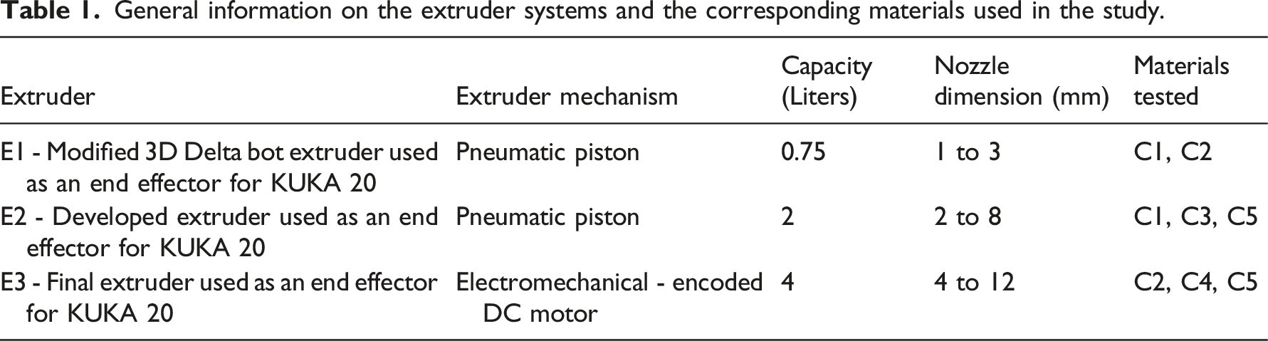
General information on the extruder systems and the corresponding materials used in the study.
The informed toolpath algorithm was developed using Rhinoceros 3D and Grasshopper as parametric environments. This algorithm facilitated adaptability to different extruder and material inputs, optimizing robotic controls such as travel speed, approach angle, and motion. It comprised geometric analysis of the designed form, analysis of required infill properties, adaptive slicing, simulation, toolpath preview, and program generation for robotic 3DP. BMADE Robots plugin was utilized for creating programs for the KUKA 20 industrial robot arm, and Daniel Piker's Kangaroo plugin was employed for material behavior simulation to prevent collapsing due to self-weight and overhang limits.
In the second phase, the proposed framework and the informed toolpath algorithm were tested by designing and RCP of an interlocking, modular wall component system. The design considerations included testing overhang limits, infill properties, changing shell thickness, and layer height. The evaluation was conducted based on surface quality, overhang limits, a comparison between the given design and the printed component, overall shrinkage after firing, and printing time.
System set-up and calibration
Design and installation of 3D clay extruder
The extruder design approach aimed to create a new setup within specified constraints. Initially, a clay extruder from a DIY Delta Printer (referred to as E1) was adapted to interface with a KUKA robotic arm as a prototype (E1) to gather preliminary results for digital design feedback. E1 employed a pneumatic piston and had limited storage with a 2 mm maximum nozzle diameter, resulting in a 1/3 scale production for testing purposes. Nevertheless, it served to establish key parameters such as speed, form height to shell thickness ratio, and initial material mixture calibrations (E1).
Figure 2 illustrates the initial setup with the pneumatic extruder and various prototypes conducting material viscosity tests. E2, an extension of E1, featured a larger container, nozzle, and more potent air compressor while still utilizing a pneumatic system (E2). Although these extruders assisted in problem-solving regarding form and material properties, the pneumatic system presented challenges. Air bubbles could form inside the material, leading to unstable air pressure and inconsistent layer thickness and density. Additionally, bursts of air towards the end of printing disrupted the process and occasionally caused collapse due to wet clay. Hence, a pneumatic system within our resources was deemed suitable only for small-scale fabrication. Initial set up with the pneumatic extruder and different prototypes with various material mixture tests for viscosity.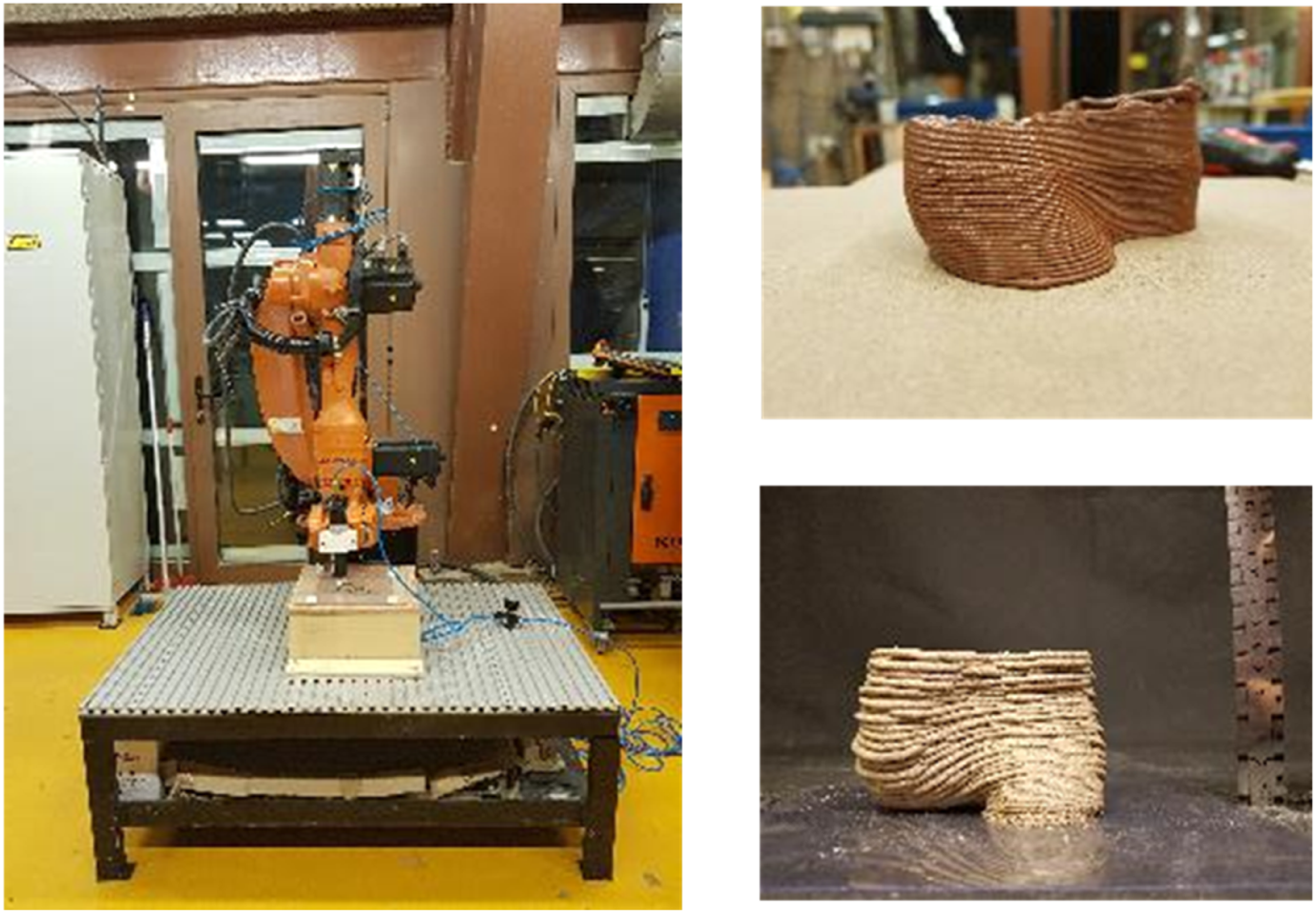
Learning from these setbacks, a new mechanical clay extruder (E3) was devised, incorporating insights from other clay extruders and previous experiments.32–35 The design considered budget constraints and lab facilities. E3 featured a larger container for 1:1 scale production, a straightforward refill mechanism, adjustable nozzle size for material deposition at varying thicknesses, and a speed control system for precise deposition on the toolpath. It also included a retractable piston and mechanism for clay compression and a clean finish at the end of the print (E3).
Figure 3 illustrates the diagram of the clay extruder, highlighting the DC motor, gear system, rod connection, and dismountable container system. An encoded DC motor-controlled speed and rotation direction within budget constraints, using a double-gear mechanism to convert rotational motion into linear motion for more consistent deposition. This setup reduced motor load. The aluminum container allowed easy refilling and cleaning from both ends, and interchangeable nozzles with valve control covered diameters from 4 mm to 10 mm (Figure 4). Diagram of the clay extruder. DC motor, gear system, and rod connection. Dismountable system for the container. Final setup for RCP.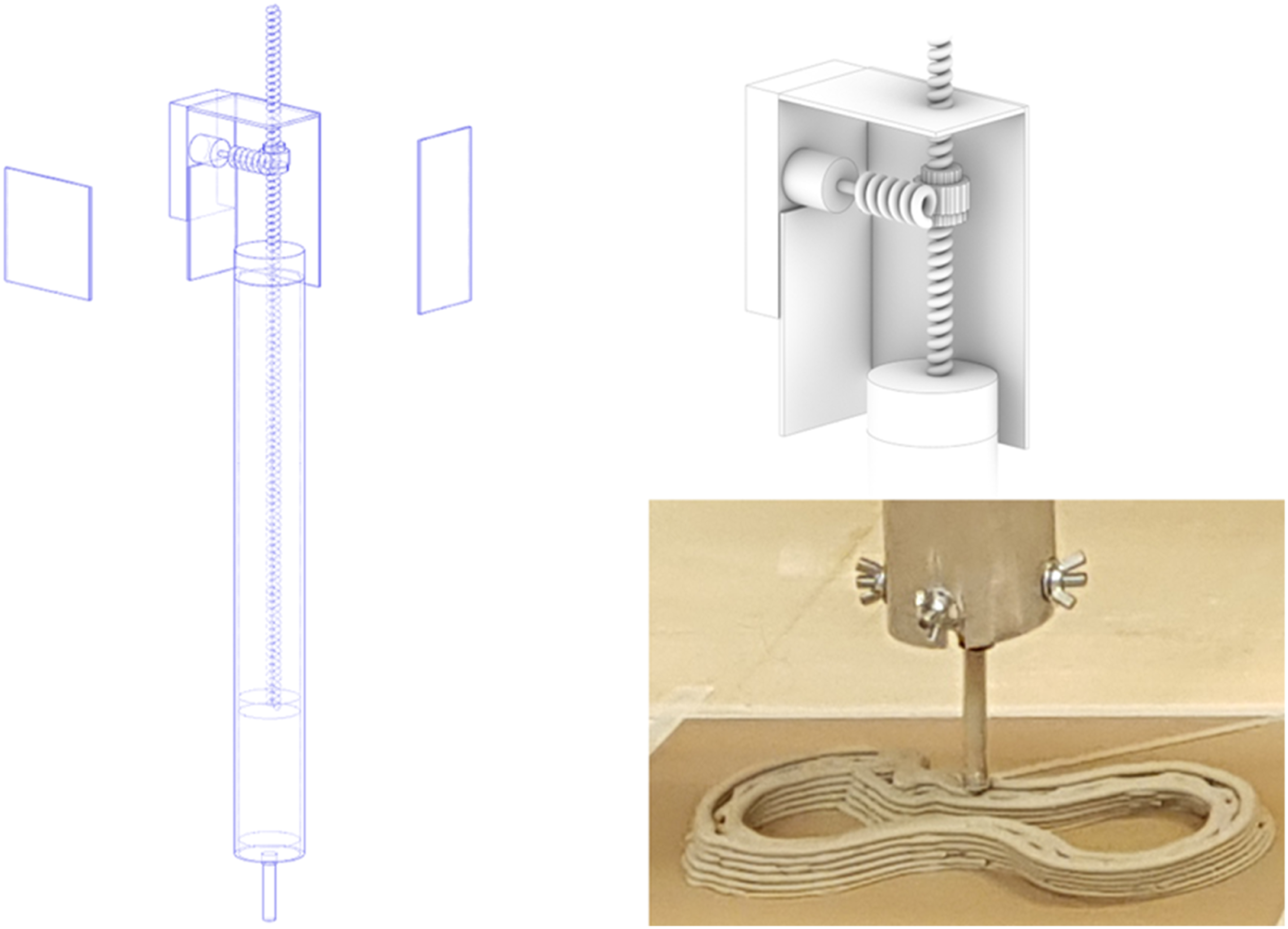
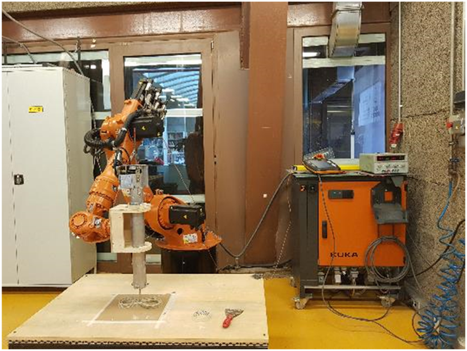
Lastly, the extruder was mounted on a KUKA 20 using a wooden frame. The encoded DC motor was linked to the DO (Digital Output) on the KUKA control panel to enable motor control through generated code. An external power supply facilitated manual control of rotation speed.
Material preparation and initial tests
Material experiments were conducted alongside the tool-making process, focusing on terracotta (C1), slip clay (C3), and locally sourced white clay (C5). Additionally, mixtures of alginate, white clay, slip clay, and water (C2, C4) were investigated. Upon the observations of tests with the mentioned mixtures, fired clay particles within the C1 improved durability in their green state but caused more cracks during drying. Additionally, the need for higher water content for C1 affects the viscosity and required power for extrusion. C2 and C4 were prepared with the alginate addition which serves as a stabilizer and could eliminate the components' firing. 22 But the alginate addition caused drastic shape change and shrinking compared to other mixtures and needed more time to optimize for RCP. Finally, C2 and C5 proved to be more ideal than other mixtures due to durability in green state, minimal shrinkage and crack formations, and stable viscosity. Between the two, C5 was selected for the final application since it required less water content and showed more consistent results with E3. Without an industrial clay mixer, mixtures were made by attaching a mixer to a hand drill. Despite the laborious nature, 16 h of preparation before printing produced usable and a uniformly hydrated mixture.
Initial tests aimed to determine the optimal viscosity for 3DP (3DP), controlled by varying water content. Higher water content eased printing but introduced complications such as increased weight per layer, susceptibility to collapsing, and reduced overhanging limits. High water content also led to imprecise form due to low viscosity and elongated drying times, causing fragility and increased crack formation. Gradual adjustments in mixture percentages and preparation methods yielded a consistent configuration for the process.
To enhance efficiency, a laminating machine was utilized to create large plastic bags from recycled materials, similar to bakery bags, improving storage, minimizing air bubble entrapment, and streamlined the filling of the extrusion container.
Prototyping and defining 3DP parameters for RCP
Consistency tests with different layer heights and printing speeds.
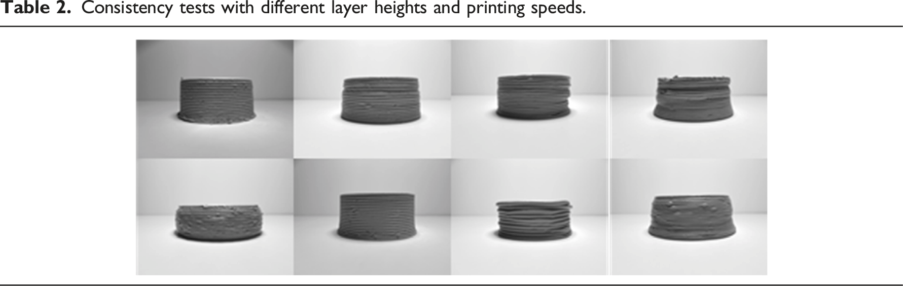
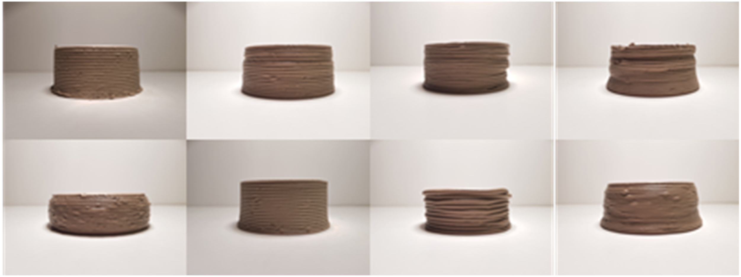
The green-state clay prints were initially weighed and measured against the digital geometry input. After air-drying for 2 days, further measurements were taken to assess shrinkage effects and identify consistent control settings. These settings yielded ranges rather than fixed values, allowing for customization and greater creative freedom in form exploration.
Designing an informed toolpath algorithm for RCP
The prototyping phase yielded crucial insights into control parameters for various clay mixtures and extruder types. These findings informed the development of a parametric algorithm within Grasshopper for RCP. This algorithm, distinct from traditional machine code generation, serves as a design medium during early digital form-finding studies. Hence, by integrating the tool and material behavior into the design process and harnessing their distinctive impact on design, rather than attempting to standardize the outcomes.
The algorithm encompasses key control parameters, including layer height, layer width, extrusion speed, travel speed, nozzle diameter, printing planes, and infill options. Users can specify the layer height, which ranges from 2 mm to 6 mm for extruder E3. Layer width, influenced by nozzle diameter and travel speed, dictates shell thickness, and allows for customization. Extrusion speed ensures deposition consistency, while travel speed is adaptable based on material behavior, setting time, initial layer stability, and sequential layer overlap, significantly influencing surface quality.
Printing planes are user-adjustable to manipulate surface resolution and enable non-linear printing. Infill options can be user-defined or determined algorithmically through a geometric analysis considering the center of gravity and overhang limits. The optimization criteria for the algorithm prioritize minimizing material usage and reducing travel time, thus preventing extended printing durations.
Homing—calibration before and after the printing process
The calibration protocol is a standard procedure in for each 3DP operation. The protocol which was specifically designed as part of the informed toolpath algorithm, is an integral part of the generated g-code and involves specific steps. Initially, the robotic arm assumes a designated home position perpendicular to the printing surface to facilitate material loading. Subsequently, the encoded DC motor initiates forward motion under the control of the robotic arm controller, allowing the clay to flow through the nozzle. To ensure a clean start, a secondary button triggers material retraction. The default calibration printing process follows, involving the printing of a consistent line parallel to the +Y axis to calibrate layer height and thickness. During this calibration line printing, the travel speed gradually increases from 30 mm/s to 60 mm/s to assess deposition uniformity and print surface evenness. Throughout the actual printing, travel speed varies between 30 mm/s and 60 mm/s, adapting to geometric, material, layer thickness, and depth requirements. After calibration, the system enters a hold state for troubleshooting and requires a secondary start to initiate printing, changing the approach angle for the first layer of the intended geometry. Upon completing the printing, the encoded DC motor retracts material, while the extruder returns to the initial material loading position, reducing travel speed to 30 mm/s to prevent collisions.
Infill properties and overhang limits
RCP offers significant advantages, mainly in the realm of form generation. The robotic arm's precision control of clay material deposition facilitates the creation of intricate geometries with precision. However, the use of clay in layer-by-layer deposition is hindered by challenges like viscosity control and fragility during drying, limiting the printable geometric forms without support material. Subsequent experimentation focused on overhang studies and infill properties to ascertain the boundaries of printable geometries. These test results informed the development of a simulation integrated into the algorithm governing the toolpath. The simulation was constructed using the Kangaroo physics engine, originally devised by David Piker to avert collapse during the RCP process.
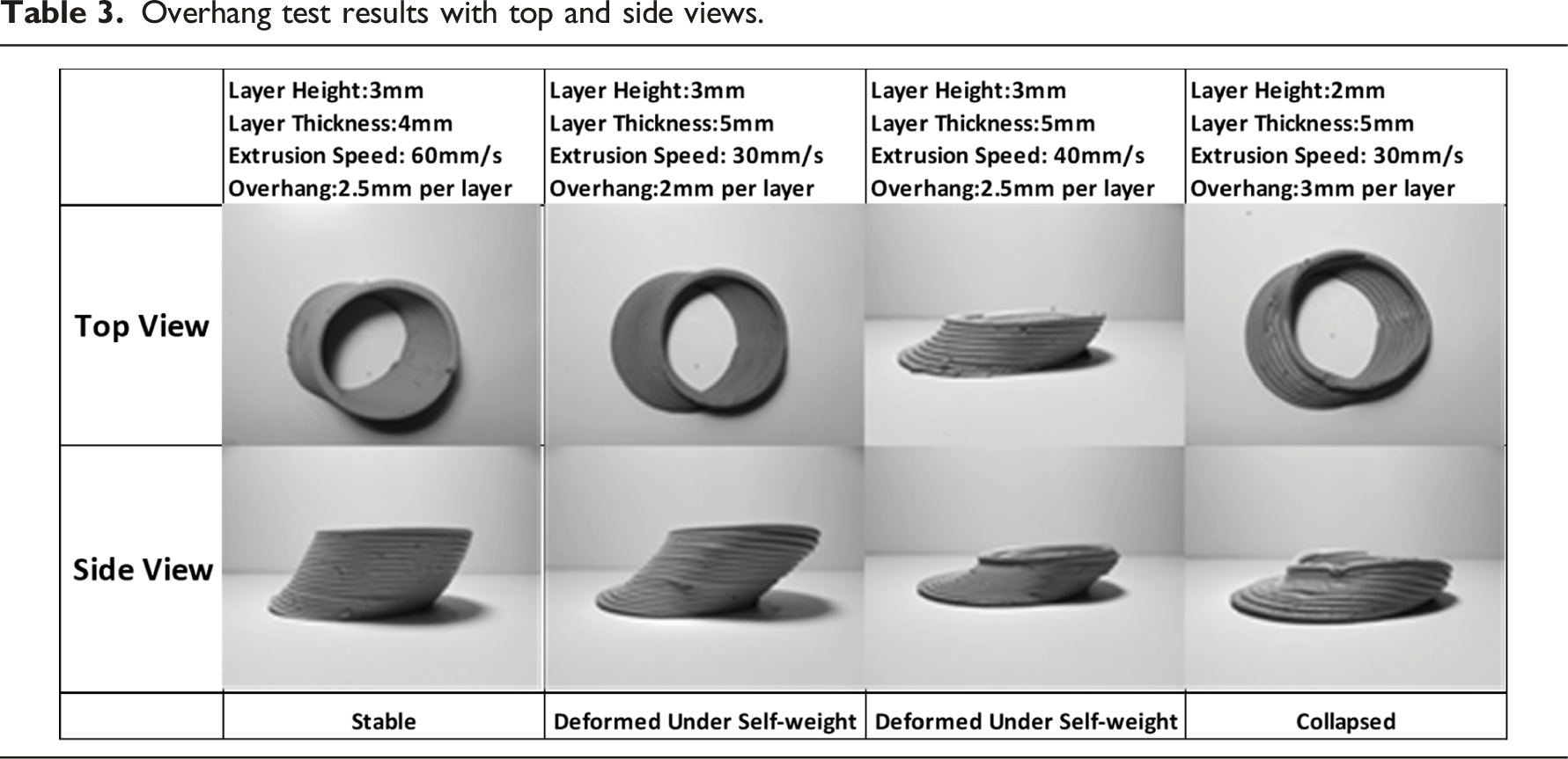
Overhang test results with top and side views.
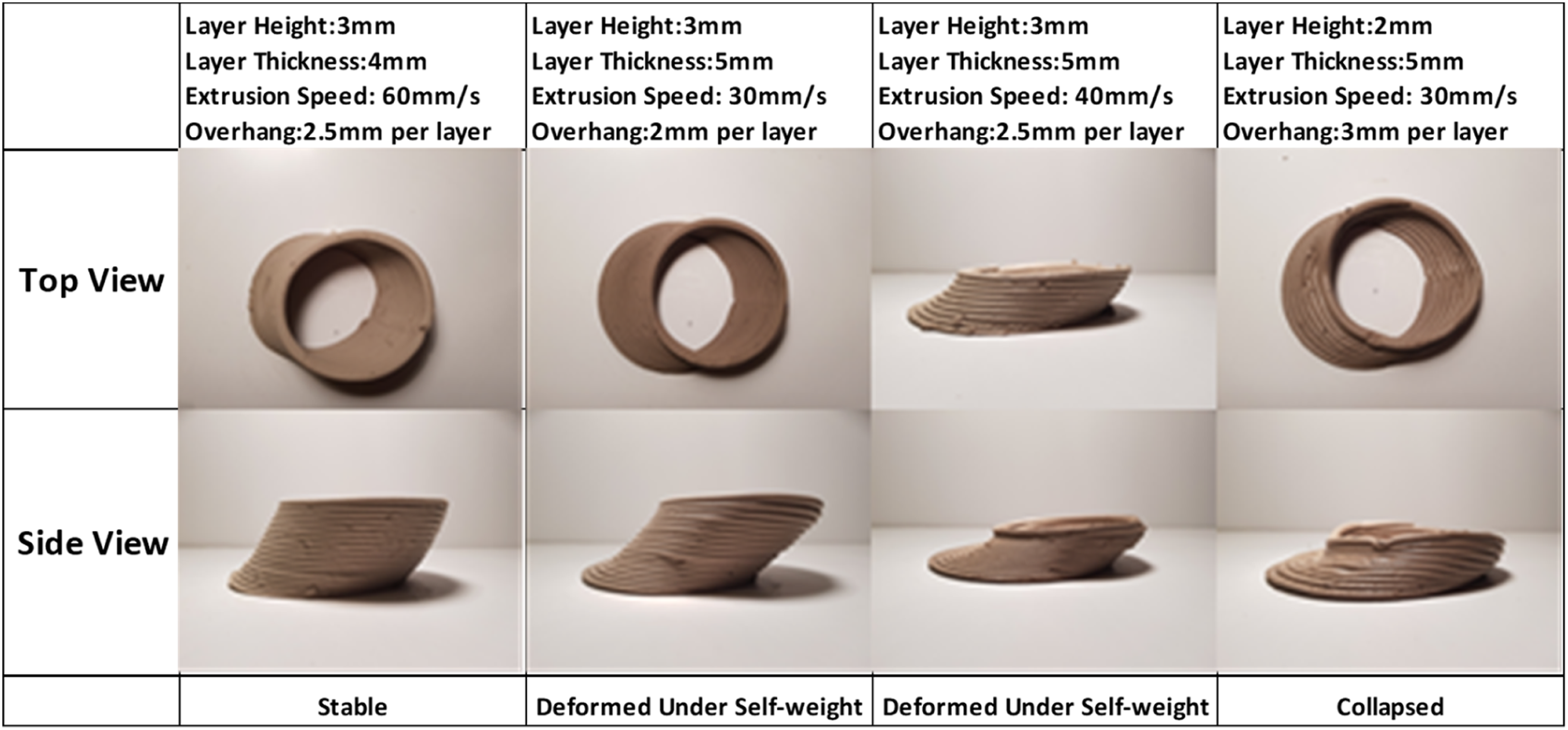
During these tests, an adaptive slicing system was integrated, deviating from uniform layer distances in favor of shorter initial layers gradually transitioning to taller ones. This approach enhanced print durability and enabled non-linear geometries by using isocurves rather than contours along the surface.
The adherence of clay to itself made it advantageous for infill design, where a method involving an inner curve touching the surface in acute angle areas and converging toward the layer center proved time- and material-efficient. By altering travel speed, the shell thickness of the infill geometry could vary from that of the surface shell, reducing printing time.
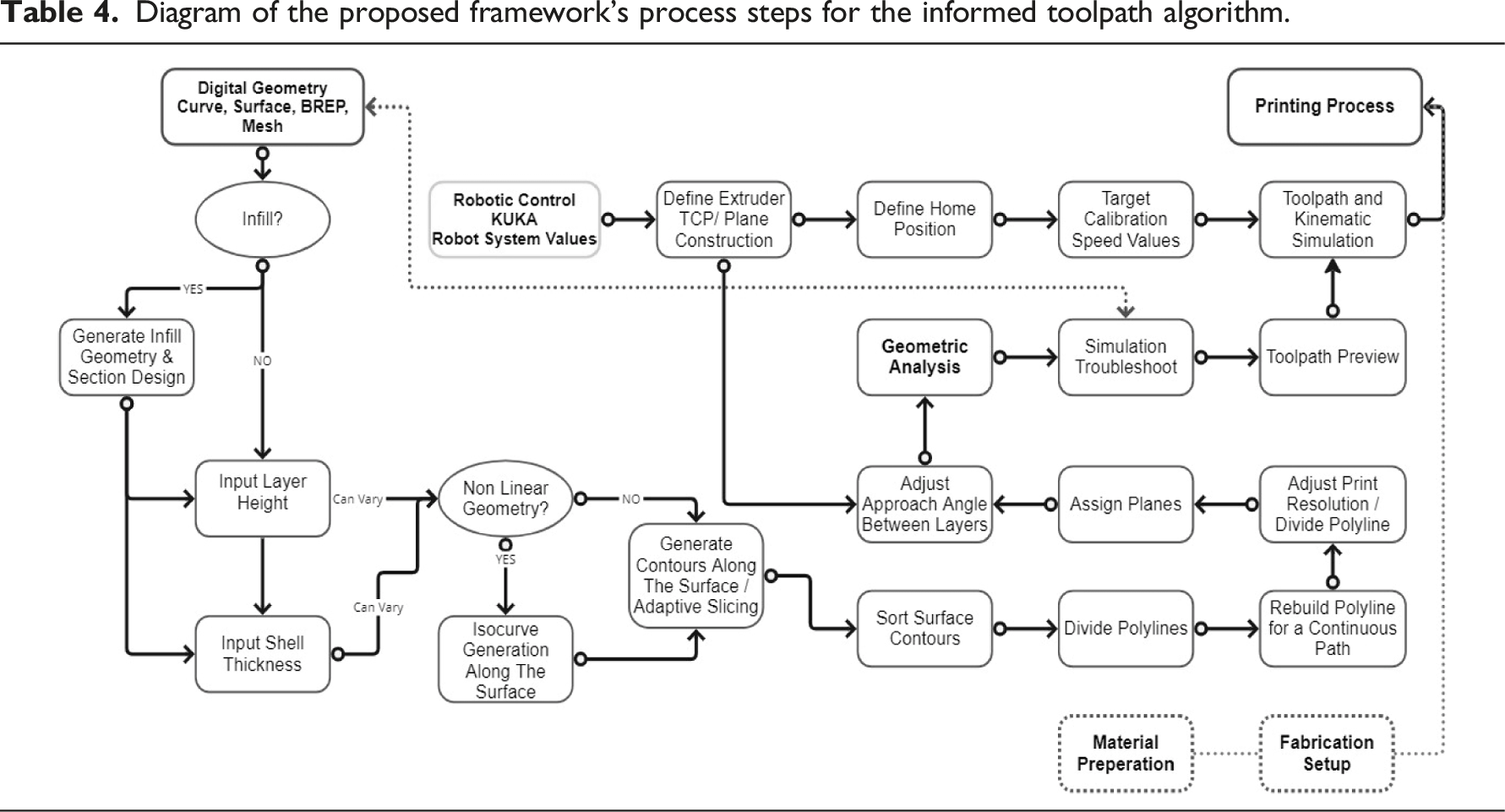
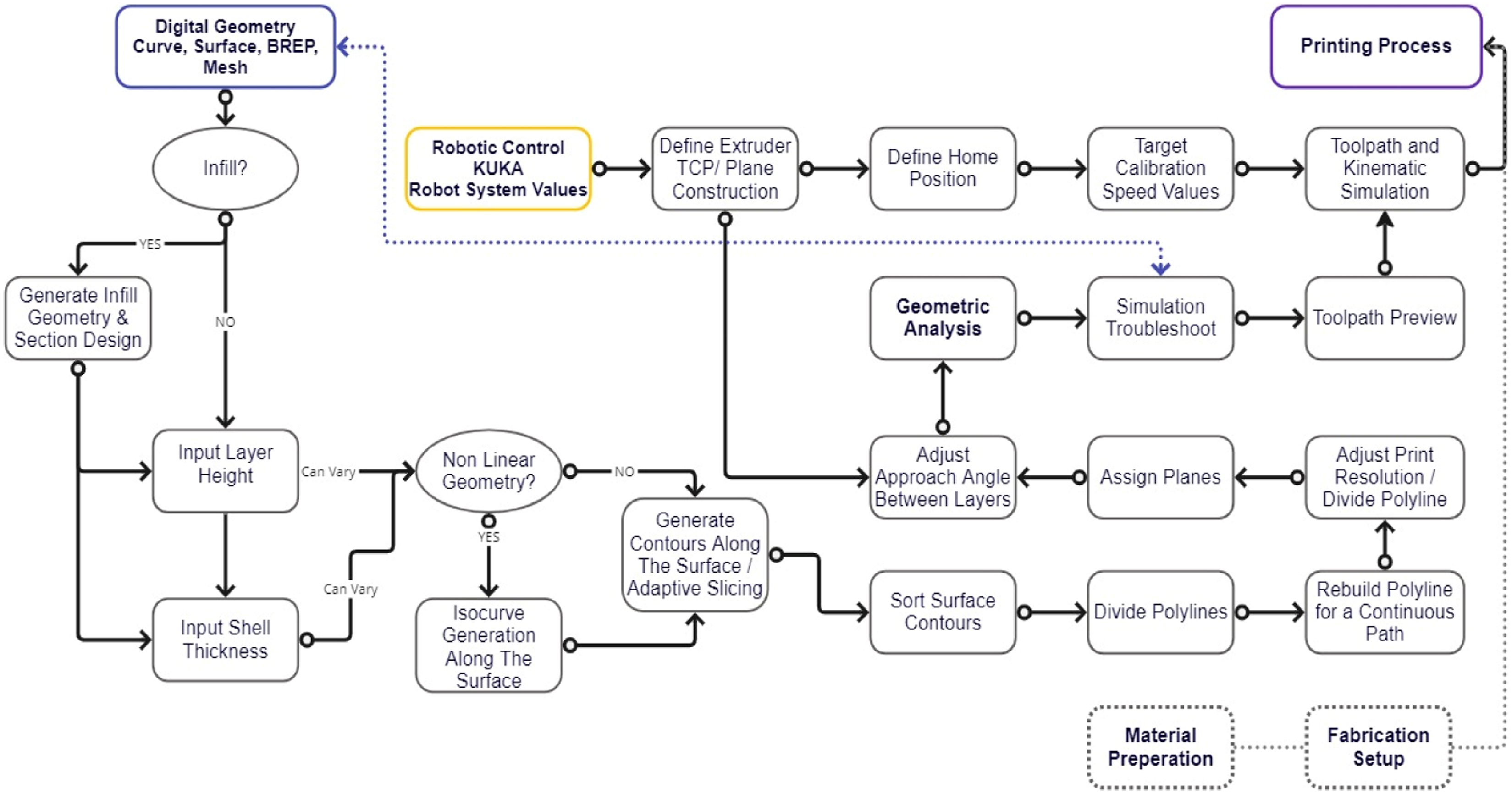
Diagram of the proposed framework's process steps for the informed toolpath algorithm.
RCP of interlocking wall components
The initial step of digital design explorations for developing a component-based wall system was to establish suitable criteria for evaluating the proposed framework. These criteria consist of an interlocking system for measuring surface quality and precision, the production of assembly-friendly details, and the creation of controlled void forms with varying insulation properties. Another objective was to create an adaptable component that could accommodate different assembly organizations for various design requirements.
Digital design parameters for a self-interlocking modular system
The design process aimed to create a modular system that self-interlocks in the XY-plane during assembly, facilitating ease of assembly and strengthening the structure through increased component contact. Controlled voids were also a priority, providing future study potentials for heat and sound isolation and thermal enhancements via fibrous materials.35–38 The exploration of tiling systems, specifically modifying Truchet's tiles, resulted in a single tile with two circular arcs of radius half the tile edge length at opposing corners. 39
This tile, with two possible orientations, created systematic gaps between closed forms. An algorithm was developed to test different combinations, leading to the selection of three closed geometries as the foundation of an adaptive brick system (Figure 5). Further investigations optimized base dimensions and 2D organization logic (Figure 6). Truchet tile and the selected emergent geometries. Plan view and dimensions of two versions of corner wall organization with two different tiles.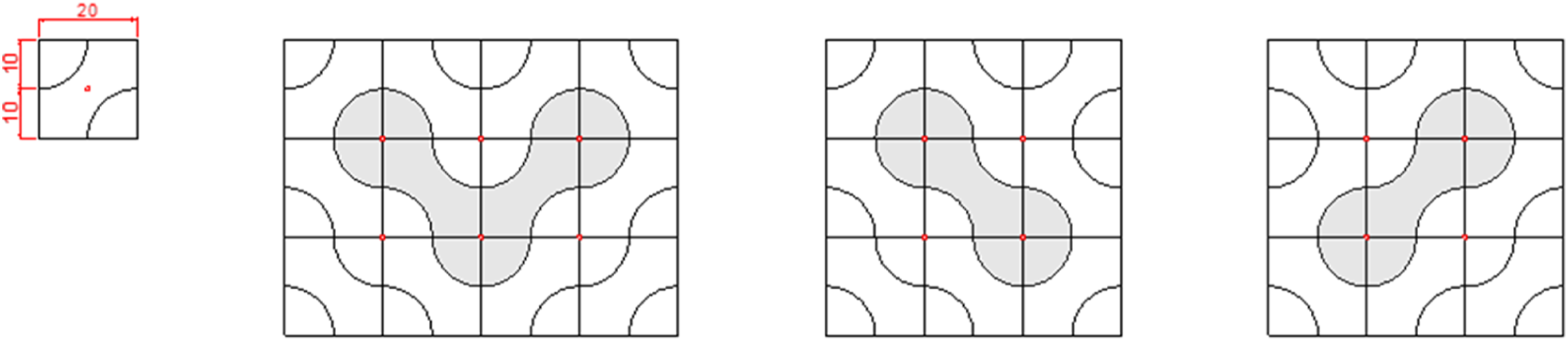
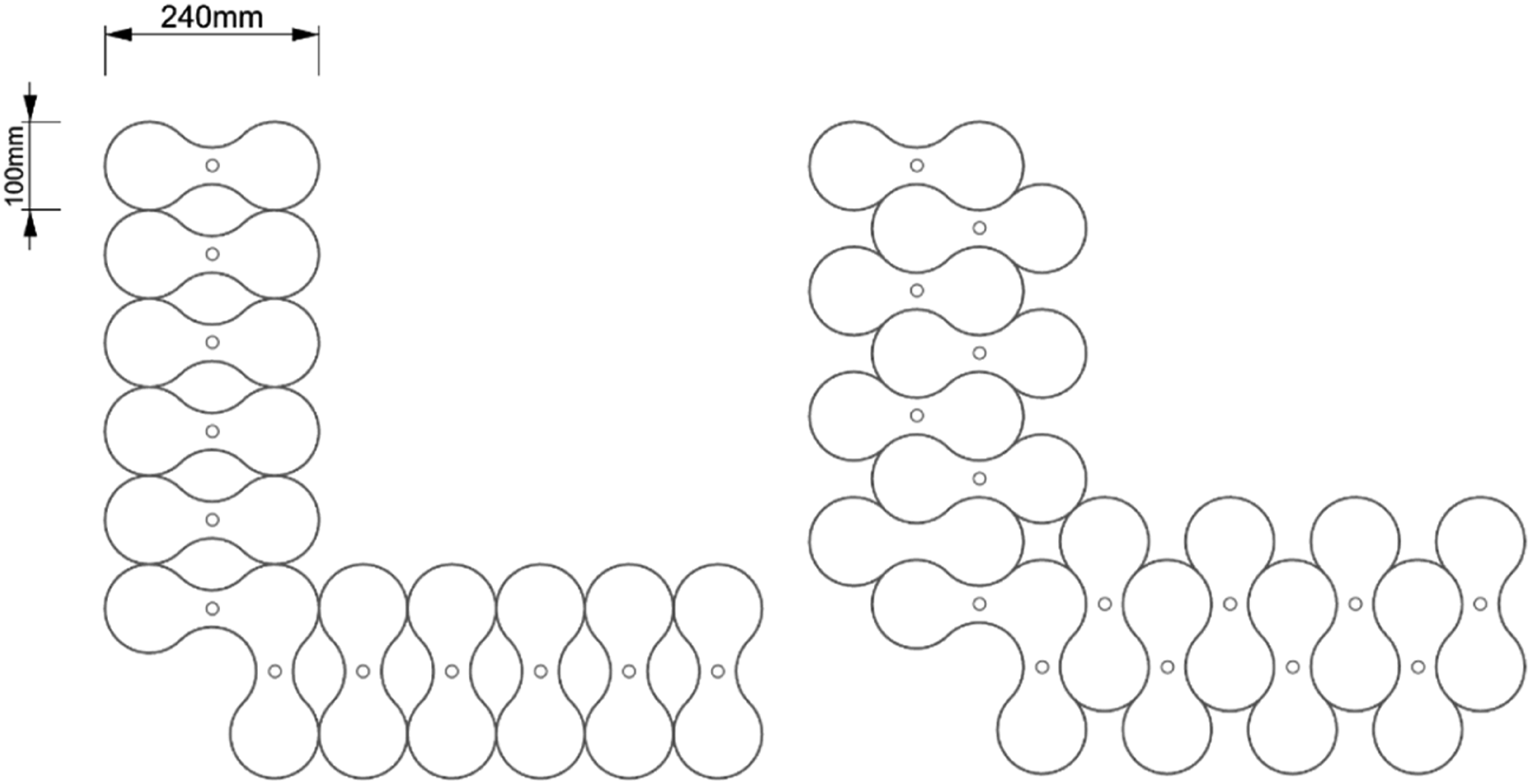
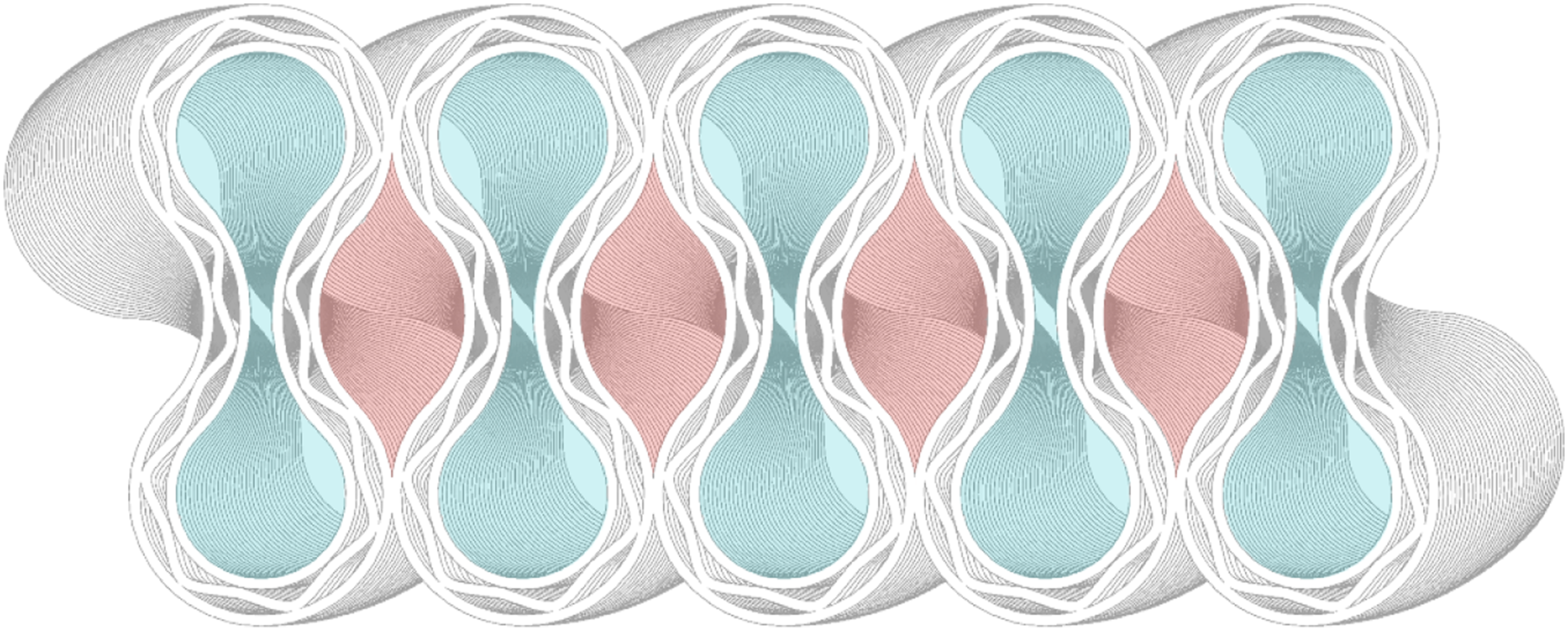
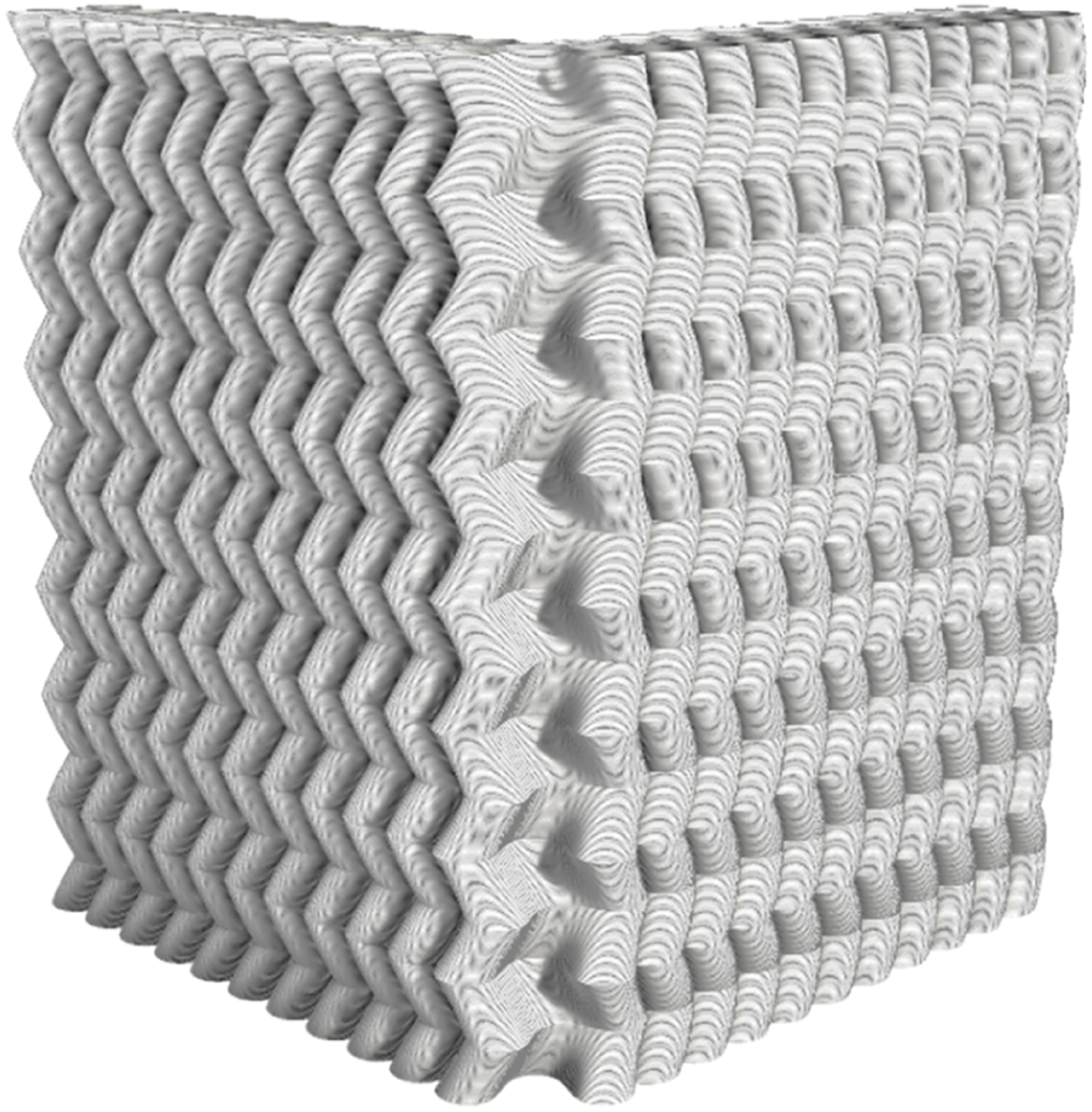
The transition from 2D to 3D geometry involved several key criteria, namely, achieving interlocking between adjacent components, optimizing infill geometry for printability, integrating stacking joint details, and considering total printing time. Component interlocking was achieved by rotating the base geometry along the Z-axis, maintaining void-forming capabilities due to Truchet tiling. The rotation angle was fine-tuned to balance joint surface area and printability, guided by material and extruder properties from prototyping. The final value for the rotation angle of a component measuring 120 mm in height was 45° creating a total overhang value of 55 mm. Simultaneously, infill geometry was adjusted to extend overhang limits while minimizing printing time. Despite the extra material required for infill, its design enhanced layer durability, bolstering clay properties, and establishing a monolithic layer system to support overhangs, reducing the risk of collapsing, and increasing print speed (Figures 7 and 8). Figure 9 showcases a possible corner wall design using the adaptable RCP modules. Modular assembly logic of the components in XY-Plane and the interlocking detail in the Z-axis. Plan of adjacent components. Red marked areas indicate enclosed voids between components, while cyan indicates continuous hollow parts of the components that can be filled with insulation materials. Corner wall visualization.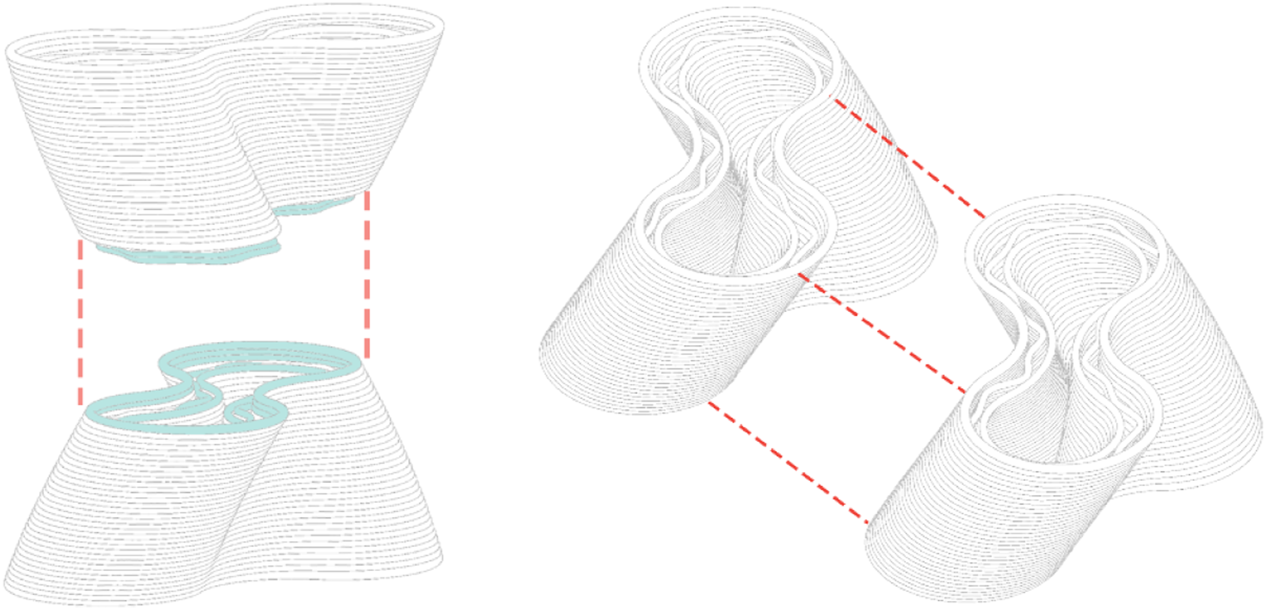
3DP control parameters and informed toolpath planning
The study aimed to assess the influence of control parameters on parametrically produced components using a developed toolpath algorithm. These components' buildability is affected by factors like geometric properties, material behavior, and fabrication parameters. Challenges in RCP include collapsing, crack formation during drying, and uncontrolled deformation. The goal of 3DP tests was to enhance buildability, support overhang layers, and decrease printing time. Key control parameters include base area to height ratio, center of mass, overhang values, shell thickness to height ratio, travel speed, printing speed, accuracy, consistency, and clay mixture properties.
Table 4 illustrates the steps of the algorithm. First, a center of mass calculation determines if infill geometry is needed. Adaptive slicing can be used for shorter layer height in the initial and end layers. For E3 with a 4 mm nozzle, optimal slicing values ranged from 2.8 to 3.5 mm. Shell thickness depends on nozzle diameter, travel speed, and printing speed, with an optimal outer wall thickness of 5 mm and 3 mm for infill. Speed control reduced printing time. Adaptive slices are sorted and divided based on curve degrees to generate printing planes, with extrusion direction changing in each subsequent layer to improve surface finish. The transition between layers also considers approach angles for the robotic arm's 6-axis movement.
Geometric analysis, focusing on center of mass changes and overlap to overhang ratios, helped troubleshoot issues. Toolpath preview and simulation were used to visualize robot actions.
Discussion of results
The two-phased methodology for RCP aimed to establish control parameters and enhance designers' control over the fabrication process through an adaptable toolpath algorithm. Material and tool tests were conducted to determine parameters like shell thickness, layer height, deposition speed, and infill design characteristics. Various locally sourced clay mixes, including red ceramic clay, white ceramic clay, granulated ceramic clay, and a mixture with sodium alginate, were explored in this phase. The evolution of extruders E1, E2, and E3, with E3 proving more consistent and suitable for architectural-scale fabrication. C5 and E3 (Table 1) were used for the final application.
Using prototyping outcomes, control parameters for RCP were determined, encompassing layer height, layer width, extrusion speed, travel speed, nozzle diameter, printing planes, and infill options. The informed toolpath algorithm incorporated an adaptive slicing system, enabling non-linear geometries and varying layer heights.
RCP offered increased freedom in form generation, allowing precise clay material deposition. The study examined overhang limits in relation to infill properties to establish printable geometries. Adaptive slicing, overhang limits, and infill design were integrated into the toolpath algorithm to streamline the process.
The final phase involved designing and 3DP an interlocking modular wall component system to evaluate the framework and toolpath algorithm. The design parameters aimed to achieve surface quality, precision, optimized printing time, and assembly-friendly characteristics. The components featured self-interlocking capabilities and controlled voids which can later be used and tested for heat and sound isolation. Evaluation criteria included the impact of 3DP control parameters, toolpath planning, RCP performance, and assembly possibilities.
3DP control parameters
The success of RCP was closely tied to 3DP control parameters and toolpath planning. The aim was to identify optimal values for key parameters, including layer height, width, extrusion and travel speed, nozzle diameter, printing planes, and infill options.
To ensure buildability and structural integrity, the study utilized an algorithm with adaptive slicing. This allowed for shorter layer heights at the initial and final layers, improving print durability. The ideal layer height fell within the 2.8 to 3.5 mm range. Layer width, influenced by nozzle diameter, travel speed, and printing speed, played a crucial role in controlling shell thickness and establishing a cohesive layer system supporting subsequent layers and overhangs.
Consistent deposition required precise extrusion speed control. Gradual adjustments in travel speed, tailored to geometric and material factors, and desired layer specifications, contributed to surface quality and overhang support. Extrusion and travel speed values were meticulously optimized, considering material properties and extruder capabilities, to prevent collapsing and ensure uniformity.
The study aimed to improve infill geometry to extend overhang limits and reduce printing time. The natural adhesion properties of clay allowed for controlled void forms, increasing surface area for interlocking components. Optimized infill geometry stabilized layers, preventing collapse due to their weight. Adaptive slicing and alteration of extrusion direction between consecutive layers improved surface finish and reduced the risk of overhang collapse.
An informed toolpath algorithm, incorporating geometric analysis, infill design, and adaptive slicing, was used to generate printing planes for RCP. The adaptability of the algorithm to various extruders and materials allowed for customization and design flexibility. Beyond generating machine codes, it served as a design tool in early digital form-finding studies, providing direct feedback between digital design and 3DP parameter control, enabling direct control over the printing process.
RCP performance
The study assessed the performance of RCP through the fabrication of an interlocking modular wall system. Evaluation criteria encompassed surface quality, precision, assembly ease, controlled void forms, insulation properties, post-firing shrinkage, and printing time.
Surface quality and overhang limits
Enhanced surface quality resulted from adjusted 3DP control parameters and an informed toolpath algorithm. Utilizing adaptive slicing and altering extrusion directions between layers improved surface finish. By manipulating layer offset, shell thickness, layer height, extrusion speed, and travel speed, we determined maximal overhangs without hindering printability (Table 3). In the case of module, the infill geometry highly affected overhang value of 55 mm in 120 mm height.
Buildability, printing time, and material efficiency
Optimized 3DP control parameters, including layer height and extrusion speed, prevented collapses, cracks, and deformations. Integration of Kangaroo's physics engine ensured stable printing. The informed toolpath algorithm optimized printing planes, infill geometry, and travel speed, enhancing efficiency. Adaptive slicing and varied layer heights reduced printing time. Each module took 40 min, from material loading to object removal, with a two-day drying period before firing. Batch firing of 18 components was feasible.
Interlocking modular system and assembly
The modular wall components achieved XY-plane self-interlocking during assembly, enhancing structural stability. Controlled voids within components and the modular assembly enabled tailored heat and sound insulation. Design characteristics allowed various assembly configurations for diverse applications (Figure 9 and 10). Some possibilities of assembly: wall, perforated walls, and column.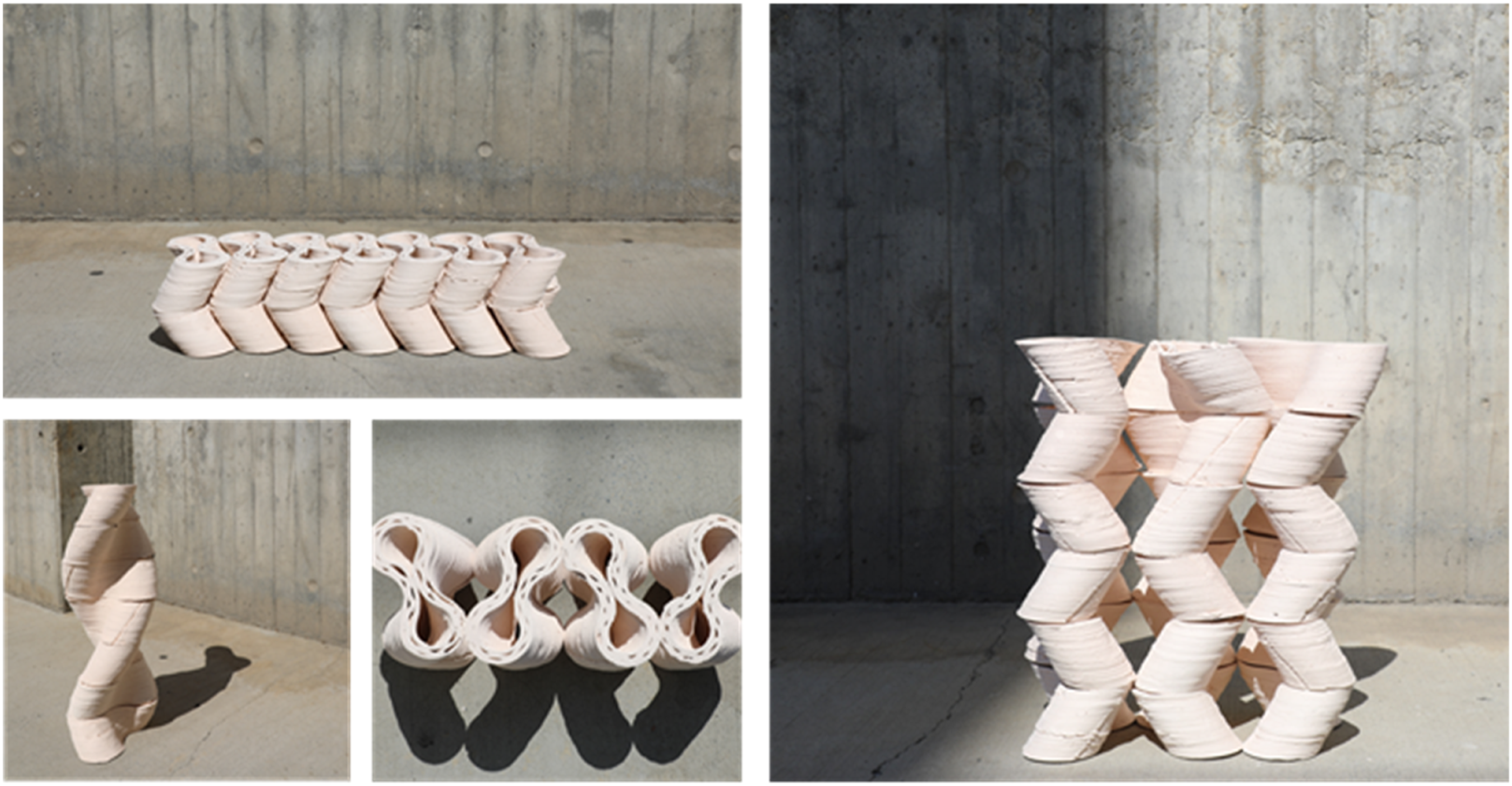
Conclusion
This study presents a methodological framework for RCP technology, focusing on locally sourced earth-based materials and architectural-scale applications. The objective is to enhance the designer's control over digital manufacturing processes and explore the integration of sustainable, traditional materials with contemporary fabrication techniques. Key contributions include the determination and optimization of critical 3DP control parameters, the development of an informed toolpath algorithm, and the application of these findings in the design and 3DP of an interlocking, modular wall component system.
The study investigates and utilizes parameters such as layer height, extrusion speed, travel speed, nozzle diameter, printing planes, and infill design. The informed toolpath algorithm, based on these findings, allows for precise control over these parameters, enhancing customization and flexibility in the printing process. It also integrates adaptive slicing, overhang studies, and infill design to improve buildability, structural integrity, surface quality, and printing efficiency.
The modular design of the wall component system offers advantages in manufacturing, reducing printing times and facilitating stacking and transportation compared to large-scale fabrication. This approach aligns with traditional earth-based material practices and promotes knowledge transfer and the widespread adoption of local materials and technologies.
The study underscores the significance of parameter control and toolpath planning in robotic clay 3DP, positioning the informed toolpath algorithm as a design medium for form-finding studies, emphasizing material properties and their influence on design. The framework and toolpath algorithm provide a systematic approach to design and construction, allowing for the manipulation of various parameters and the incorporation of traditional and locally sourced materials into contemporary design processes.
Further research may explore different clay mixtures, extruder mechanisms, and parameter optimization for specific architectural applications. Additionally, investigating the integration of reinforcement elements such as fibers or armature to enhance the structural performance of printed components may be beneficial in real-world construction scenarios.
Footnotes
Acknowledgments
We would like to express our sincere gratitude to Istanbul Bilgi University, Department of Architecture, for their invaluable support throughout this study. We also extend our heartfelt thanks to Rahman Çelebi for his expertise and meticulous attention to detail, which have greatly enhanced the quality of our work.
Declaration of conflicting interests
The author(s) declared no potential conflicts of interest with respect to the research, authorship, and/or publication of this article.
Funding
The author(s) disclosed receipt of the following financial support for the research, authorship, and/or publication of this article: This work was supported by the Bilimsel Araştırma Projeleri Birimi, İstanbul Teknik Üniversitesi 39486.