
Abstract
Electric light sources, including displays and luminaires, often exhibit rapid light fluctuations called temporal light modulation (TLM). TLM can be seen as their electrical footprint. This work demonstrates that TLM can be remotely detected and used to perform in situ photometric and spectroradiometric measurements of very low light levels superimposed to intense backgrounds. Illuminance levels about 500 000 times smaller than the background were reliably measured by lock-in detection, allowing photometric measurements to be performed during daytime, even with sunny conditions. Using a new type of optical lock-in spectrometer, it becomes possible to retrieve spectral quantities through the TLM of the light source. The spectral distribution of an LED lamp was measured against a daylit background more than 1500 times brighter. Lock-in detection is an excellent technique to perform in situ measurements of electric light, even at very low level, in the presence of daylight and other background lights, opening interesting opportunities to characterize anthropogenic light pollution.
1. Context and objectives
The luminous urban environment is a mixture of lights emitted by a variety of sources, including electric light sources such as streetlights, and natural light sources in the sky. Most electrical lights are used for well-defined purposes: visibility of pedestrians, safety of drivers, signalling, advertisement, etc. The photons emitted by these common light sources follow complex paths through the built environment, undergoing multiple reflections and transmissions. As a result, light is often found in unexpected locations raising the issue of night-time light pollution associated with undesirable environmental and human impacts. 1 The most emblematic manifestation of the phenomenon is the urban sky glow, made of photons emitted by electric light sources, ending up propagating though higher atmospheric layers where they are scattered by natural and artificial aerosols, veiling the night sky. 2
The urban sky glow reflects the mix of electric lights at the scale of the whole city. 3 At a smaller scale, the luminous environment is dominated not only by nearby luminaires, 4 displays and signs, 5 but also by obtrusive light coming from light sources located farther away, 6 or coming from the sky glow itself. 7 Consequently, the night-time urban luminous environment is ‘noisy’: it is an ever-changing mix of many light sources of different categories operating with different schedules.
This complexity makes it difficult for local and national governments to enforce and improve the existing regulations on lighting and other luminous installations because in situ measurements are sensitive to the total light falling on the sensor of measuring devices. The sensor cannot differentiate photons emitted by different categories of light sources. As a result, when measuring the horizontal illuminance given by a road lighting installation, nearby luminous signs and billboards should be switched off, which is not easy to do because they are not managed by the city authorities. Similarly, the vertical illuminance created by a digital display at the façade of a residential building cannot be measured if street lighting luminaires also send light on the façade. Low light measurements are further complicated by the influence of the moon, the sun and the natural luminosity of the sky. 6
The objective of this work is to introduce a new method to sort out light in complex luminous environments. It takes advantage of the footprint of electrical lights: the temporal light modulation (TLM) induced by their power supply. 8 An implementation of lock-in detection has been recently developed to allow an optical measurement device, such as a photometer or a spectroradiometer, to be locked to the TLM of a given light source and reject background and parasitic lights that are not modulated or modulated at other frequencies.
2. Principle of lock-in detection
Lock-in detection is a well-established technique to measure the amplitude and phase of a modulated signal in the presence of noise, background and parasitic signals. Lock-in amplifiers are commonly used in many types of physical measurements to extract small, modulated signals buried in noise. 9
The principle of lock-in detection is to multiply the noisy signal by a reference signal defined as a pure sine wave locked to the frequency and phase of the modulated component to measure. The resulting product includes alternating components at various frequencies (sum and difference of each frequency in the signal with the reference frequency). The only continuous component remaining after the multiplication is the component of the signal at the exact reference frequency. A low-pass filter is used to keep this continuous component and filter out the others.
In practice, a dual-phase approach is often used in lock-in detection. The lock-in operations (multiplication followed by low-pass filtering) are applied using the reference sine wave in a first channel, the in-phase channel. In a second channel, the quadrature channel, the reference sine wave is shifted by 90°. The output of the two channels are respectively the real part X and imaginary part Y of the Fourier component of the signal at the frequency of the reference signal. They can be combined to generate the amplitude A and phase φ of the modulated signal using Equations (1) and (2):


Figure 1 illustrates the principle of lock-in detection. When the signal to measure is generated by a sensor having an electrical output, such as a photometer, the use of a commercially available lock-in amplifier is the most common approach to perform lock-in detection.
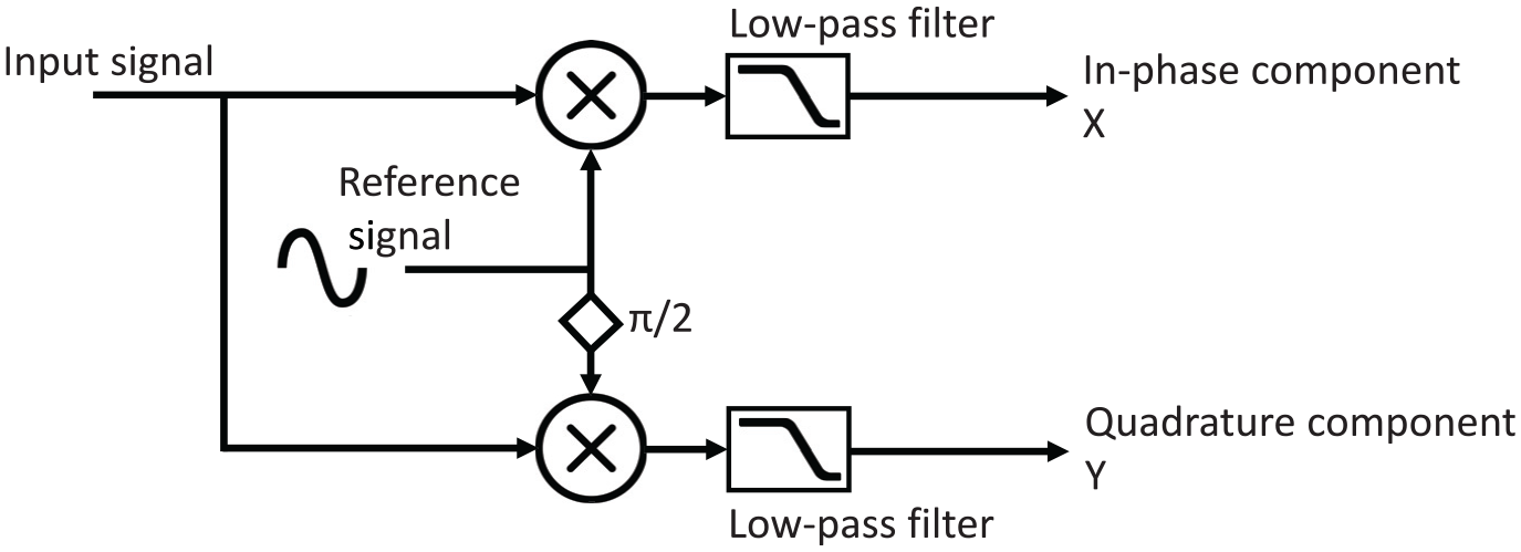
General principle of lock-in detection
The dynamic reserve of a lock-in amplifier defines its ability to recover the signal from a determined noise level. It is the ratio of the largest tolerable noise signal to the amplitude of the full-scale modulated signal to measure. Lock-in amplifiers have a dynamic reserve of about 120 dB, meaning that they can measure modulated signals about a million times smaller than the background level. For instance, when measuring light at a luminance level of 1 cd m−2, lock-in detection should be able to extract a modulated luminance signal of an amplitude of about 1 µcd m−2. This luminance level is about 200 times less than a typical night sky background without any ground-based light pollution. 10 When measuring illuminances at a typical level of 10 lx, lock-in detection should be able to detect modulated signals of about 10 µlx in amplitude, which corresponds to the vertical illuminance given by a street lighting luminaire located at 10 km from the photometer and emitting with a typical intensity of 1000 cd.
3. Principle of optical lock-in spectroscopy
In the field of optical spectroscopy, lock-in detection is not straightforward to implement. There is no commercially available spectroradiometer that comes equipped with lock-in detection. Compact array spectrometers used in photometry and colorimetry have a high number of output spectral channels, typically a few hundreds or thousands, far above the maximum number of available inputs of lock-in amplifiers.
3.1 Dual-phase approach
A dual-phase optical lock-in spectroscopy instrument was initially developed to provide lock-in detection in a parallel and multichannel fashion for all the spectral output channels. 11 This optical lock-in spectrometer applied the concept of lock-in detection depicted in Figure 1 but transposed to the optical domain. Two identical compact array spectrometers were used in parallel and synchronized in-phase quadrature thanks to optical modulators. This concept is illustrated in Figure 2. The dual-phase optical lock-in spectrometer was first used to study the spectral features of TLM. 12 The spectral power distribution of the temporally modulated radiant flux of different lamp technologies was measured in an integration sphere, providing useful insights about the physical processes involved in the production of light. It was shown that the lock-in method could be applied to perform spectral and colour measurements of LED lamps and luminaires exhibiting TLM.
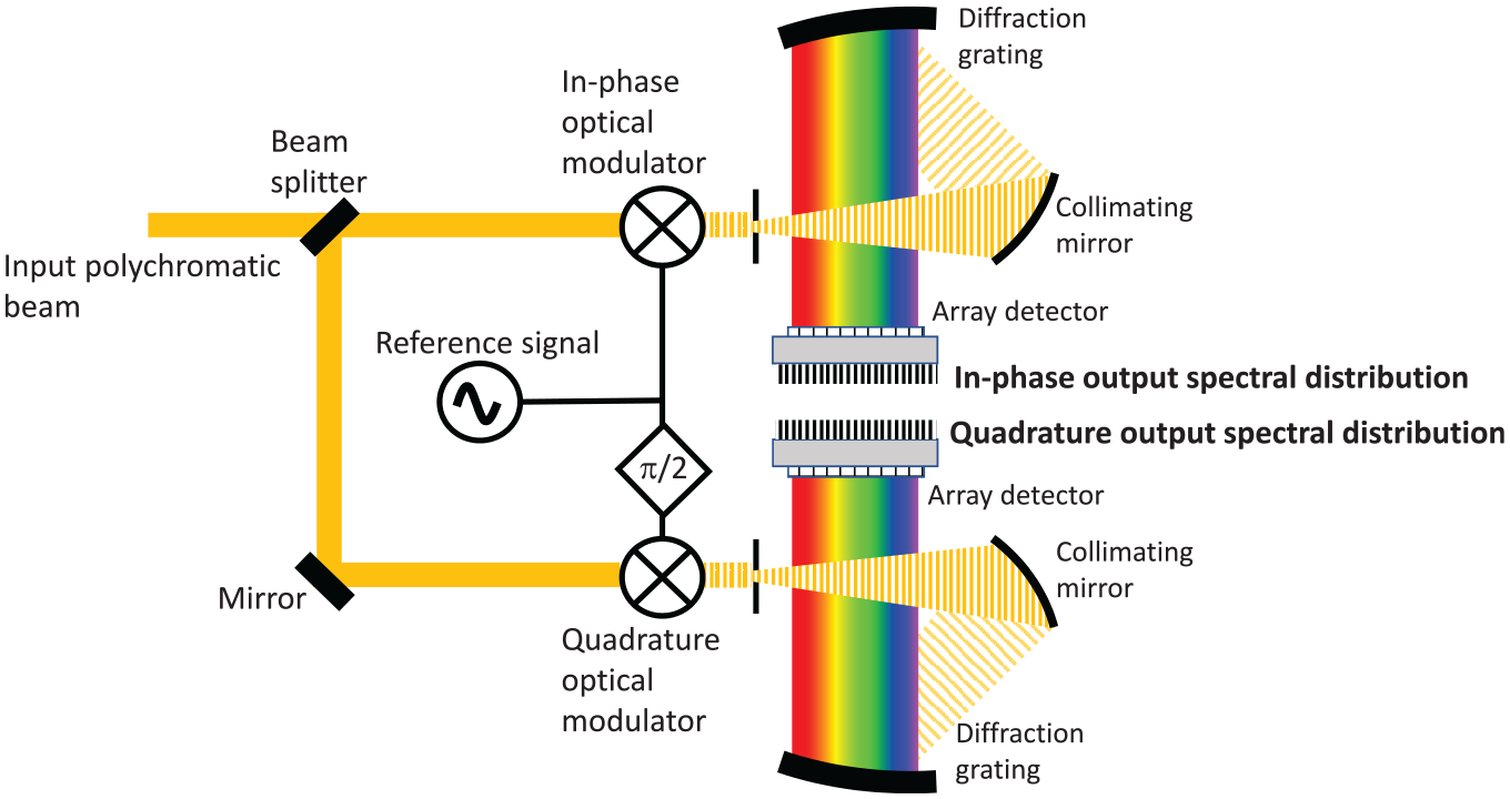
Principle of the dual-phase optical lock-in spectrometer
The dual-phase optical lock-in spectrometer required measuring the dc spectral distribution in real time to provide correct readings of the in-phase and quadrature spectral distributions. 12
3.2 Four-phase approach
A faster implementation of optical lock-in spectroscopy can be achieved by using an instrument based on a four-phase approach, in which all four quadrature components are measured at each modulation cycle, avoiding the dc compensation required by the dual-phase lock-in spectrometer. A straightforward design would consist in extending the scheme of Figure 2 to four compact array spectrometers working in parallel with external optical modulators. However, it is possible to design a simpler four-phase lock-in instrument without any external modulator by using a single compact array spectrometer fitted with an array detector having an electronic global shutter associated with an external trigger. Using a clock signal synchronized at four times the modulation frequency, the compact array spectrometer acquires continuous sequences of quadrature spectral distributions in real time which are buffered and transferred to low-pass filter units. Figure 3 shows the principle of the four-phase optical lock-in spectrometer used in this study.
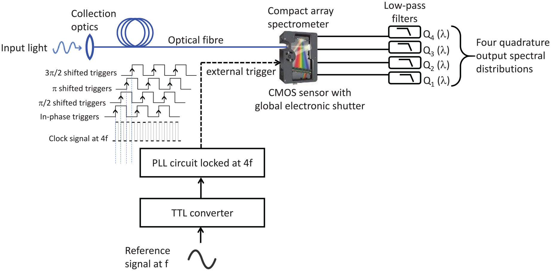
Principle of the four-phase optical lock-in spectrometer
3.3 Theory
A polychromatic optical input beam is supposed to include temporally modulated spectral components. The corresponding optical signal
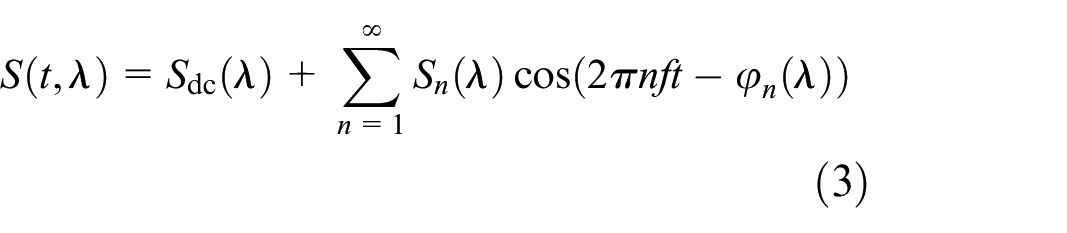
where f is the fundamental modulation frequency, n is the harmonic order,
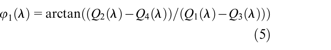
Using Equation (6), the sum of the four quadrature spectral distributions provides the dc spectral distribution:
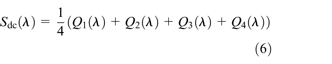
Equations (4) to (6) are the only calculations involved in the four-phase optical lock-in spectrometer. Neither storage of time-domain data nor signal processing is necessary for its operation in real time.
3.4 Experimental setup
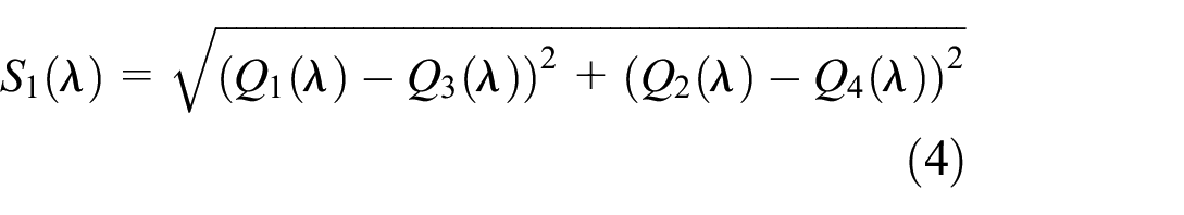
The experimental setup is shown in Figure 4. A multimode optical fibre is used to send the input light to a compact array spectrometer (FX with a 2048-pixel Hamamatsu S11639-01 linear silicon CMOS array detector, Ocean Optics, Orlando FL, USA) equipped with external triggering and buffering capabilities. The generation of the clock signal and the phase-locked loop (PLL) are achieved by the digital signal processing unit of a lock-in amplifier (MFLI 500 kHz, Zurich Instrument, Zurich, Switzerland). All the components used in the optical lock-in spectrometer can be operated with standard battery packs. The equipment is therefore portable and can be used on site.
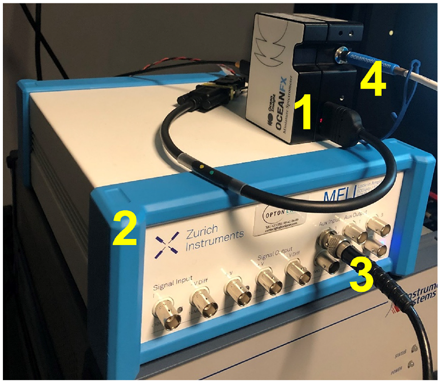
Photograph of the four-phase optical lock-in spectrometer. (1) Compact array spectrometer; (2) Clock generator and PLL unit; (3) TLM reference input signal; (4) Optical fibre input
4. Remote sensing of TLM
The aim of this work is to demonstrate the capability of lock-in detection to measure a small modulated light component superimposed to a large and unsteady luminous background. A reference modulated signal is required. For this reason, a remote sensing assembly was designed to measure the TLM waveform in situ at a distance up to about 100 m. It is built around an astronomical Newtonian telescope (reference 21024, 300 mm focal length, 76 mm aperture, Celestron, Torrance CA, USA) equipped with a silicon photodiode (SM05PD3A, Thorlabs, Newton NJ, USA) placed at the focus of the spherical primary mirror, instead of the eyepiece. The photodiode is connected to a transimpedance amplifier (AMP100, Thorlabs, Newton NJ, USA). The photodiode and transimpedance amplifier are dc-coupled to be able to measure the ac and dc components of the waveform. The remote sensing device has a field of view of about 0.5°, allowing the experimenter to select the light source of interest by aiming in its direction and obtain a time-domain signal corresponding to the temporal waveform of interest.
When measuring a ‘mixture of light’, the optical component to extract from the environment can be chosen by pointing the telescope to the light source of interest (luminaire, sign, display, etc.) using the standard finder scope attached to the telescope. Figure 5 shows a photograph of the remote sensing telescope designed to detect TLM.
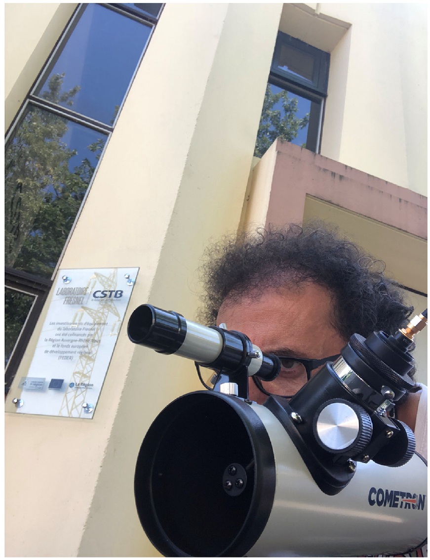
Photograph of the remote sensing telescope designed to measure TLM on site
The quality of the TLM reference signal is very important in lock-in detection. This signal should be clean, with a well-defined frequency and phase. Lock-in detection works well with a modulation greater than a few percent. With a modulation of less than about 1%, lock-in detection also works but may require a longer integration time. The reference signal can change slowly with time as long as the signal-to-noise ratio is good enough to allow the PLL circuit of the lock-in amplifier or the lock-in spectrometer to follow these variations in real time.
If the reference signal is too noisy or mixed with another TLM signal from a neighbouring light source, then the synchronization may be lost, unlocking the instruments. In this case, a clean reference signal can be generated by using a clock generator set at the precise frequency of the TLM of the light source of interest. In this case, the TLM frequency of the light source must be known and should not vary outside the bandpass of the lock-in instrument. The bandpass is the inverse of the time constant of the low-pass filters of the lock-in instrument. 9 When TLM occurs at twice the mains frequency, lock-in detection works very well with an internal reference signal because the mains frequency is stable and known with high accuracy.
5. Experimental results
Two experiments were carried out to demonstrate the performance of lock-in detection applied to photometric and spectroradiometric measurements of electric lights outdoors under variable daylight. A daylit environment was chosen to provide a very strong luminous background created by the variable direct and indirect sunlight components falling on the sensors and on the light source itself during the measurements.
5.1 Lock-in illuminance measurements
In this experiment, the objective was to measure the illuminance level given by a colour-tuneable consumer LED lamp (Smart Light, Avanquest, Hangzhou, Zhejiang, China) set to pure green at 50% of the maximal intensity, in the presence of a strong and varying daylight.
The lamp was installed on a light fixture placed outdoors in the daytime under a clear sky during summer. The remote sensing telescope was set at 5 m from the lamp and aligned to obtain the temporal light waveform which was directly displayed on an oscilloscope. The waveform measured by the remote sensing telescope aimed towards the LED lamp revealed a modulation frequency of 486 Hz and a rectangular shape with a duty cycle of 50%. After aligning the telescope, the output of the transimpedance amplifier was connected to the analogue-to-TTL converter which in turn fed the reference input of a lock-in amplifier (SR830, Stanford Research Systems, Sunnyvale CA, USA). TTL is a standard of digital signals having two logic levels corresponding to voltages of about 0 V (low level) and about 5 V (high level).
A calibrated illuminance head (PD-9310A-1, responsivity of 2651 nA lx−1, Gigahertz Optik, Tuerkenfeld, Germany) was placed at 7 m from the lamp. It was connected to a transimpedance amplifier (AMP102, Thorlabs, Newton NJ, USA) having an adjustable gain chosen to be either 100 kV A−1 (gain used in shady conditions) or 10 kV A−1 (gain used in full sunshine). The output of the amplifier was connected to the signal input of the lock-in amplifier. The experimental setup is shown in Figure 6.
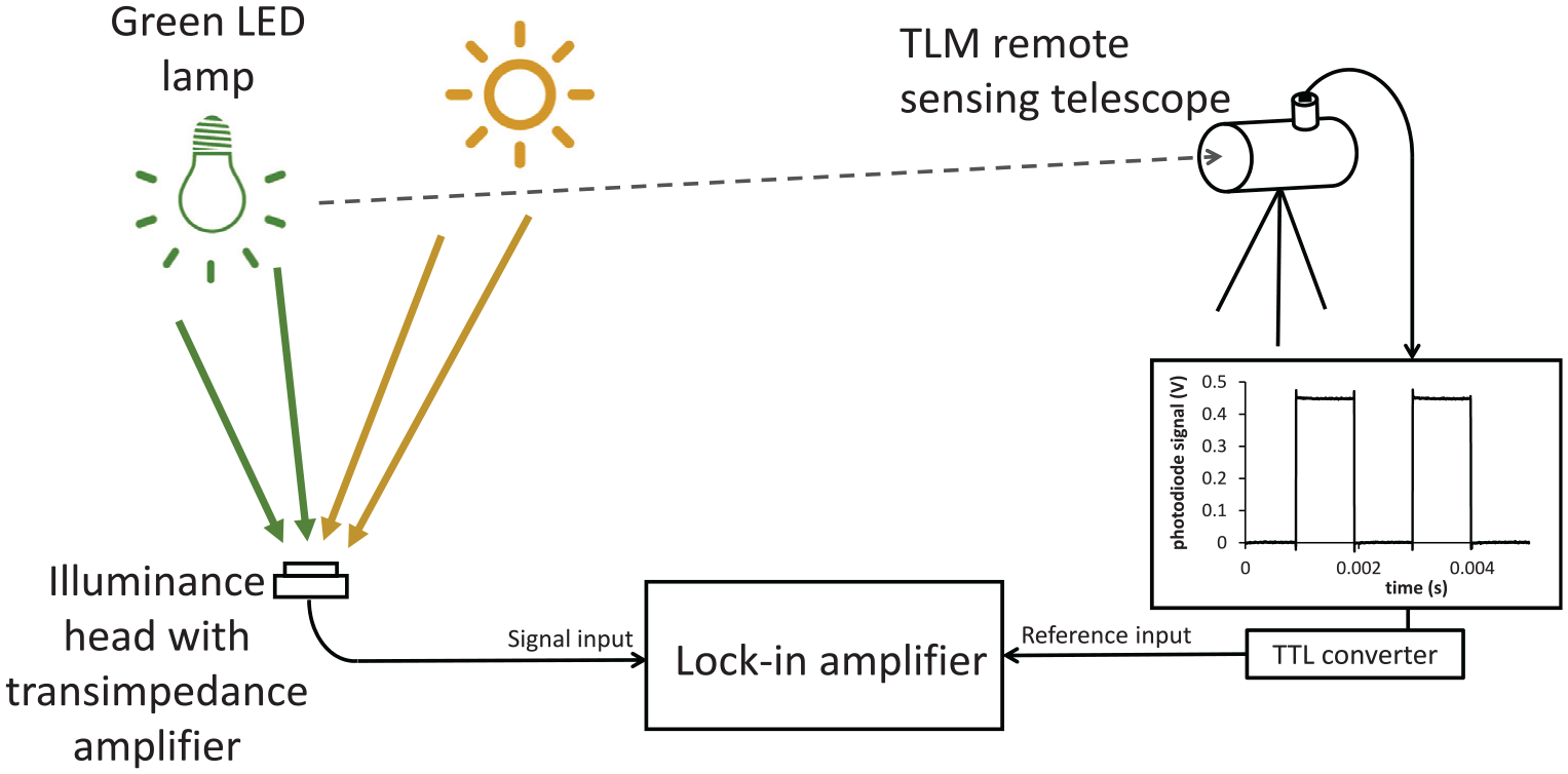
Schematic diagram of lock-in illuminance measurements performed under daylight
The experiment was performed outdoors in front of a building (Figure 7). During the first hour of the experiment, the illuminance sensor was in the shade. During the second hour of the experiment, the sun shone directly on the sensor. In these two conditions, the amplitude and phase of the modulated signal created by the lamp at the sensor surface were recorded, in addition to the dc values. These voltage signals were converted to photocurrent values using the gain of the amplifier. The illuminance values were then determined using the calibrated responsivity of the illuminance head.
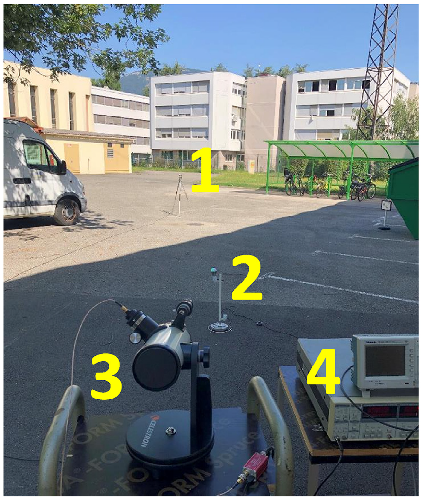
Photograph of the first experiment. (1) Illuminance sensor; (2) LED lamp; (3) TLM telescope; (4) Lock-in amplifier
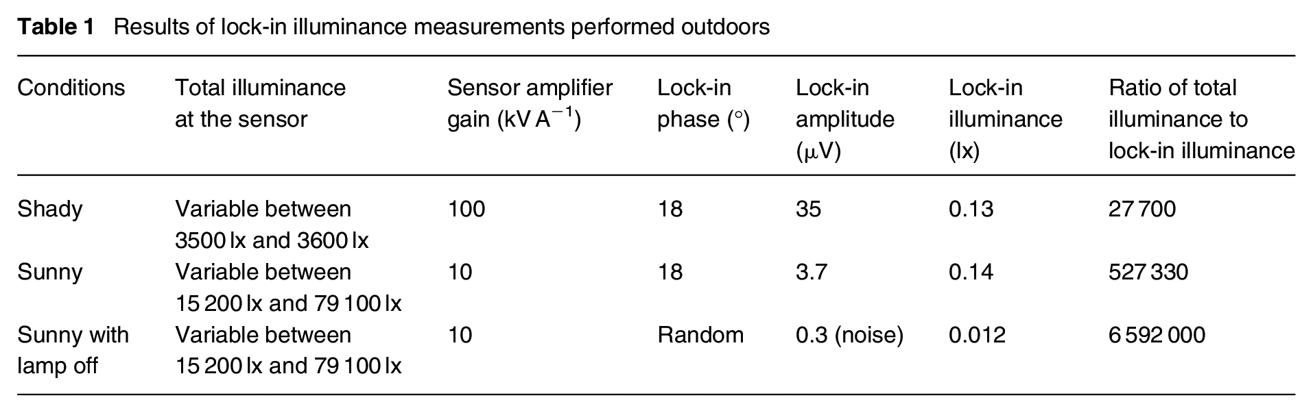
During the ‘shady’ part of the experiment, the illuminance at the sensor varied between 3500 lx and 3600 lx. The lock-in illuminance was measured with a stable phase and an amplitude of 0.13 ± 0.02 lx. During the ‘sunny’ part of the experiment, the illuminance at the sensor varied between 15 200 lx and 79 100 lx. The lock-in illuminance was again stable at 0.14 ± 0.02 lx and very close to the value measured in the shady condition. This illuminance value is about 500 000 times less than the total illuminance on the sensor. After this stage, the measurement noise was assessed by performing measurements in sunny conditions with the lamp turned off. Table 1 summarizes the results.
Results of lock-in illuminance measurements performed outdoors
The ‘true’ illuminance given by the lamp could not be measured during this experiment because the outdoor ambient illuminance was always much greater, even at night. However, the luminous intensity of the lamp was measured in the laboratory and gave 3.2 cd. Using the inverse square law, it is possible to determine the illuminance at 7 m, which is 0.065 lx.
The lock-in technique does not measure the true illuminance, but the Fourier amplitude of the modulated illuminance. Since the modulation waveform was a square wave, the Fourier amplitude is 4/π times the height of the square wave, and 8/π times the true illuminance level. Multiplying 0.065 lx by 8/π gives 0.17 lx. The lock-in illuminance measurement was about 0.14 lx. The slight discrepancy may come from the distance between the lamp and the illuminance sensor that might have been slightly underestimated.
5.2 Lock-in spectral radiance measurements
The objective of the second experiment was to measure the spectral radiance of the green LED lamp outdoors, placed under direct sunlight, using the four-phase optical lock-in spectrometer. The principle of this experiment is shown in Figure 8.
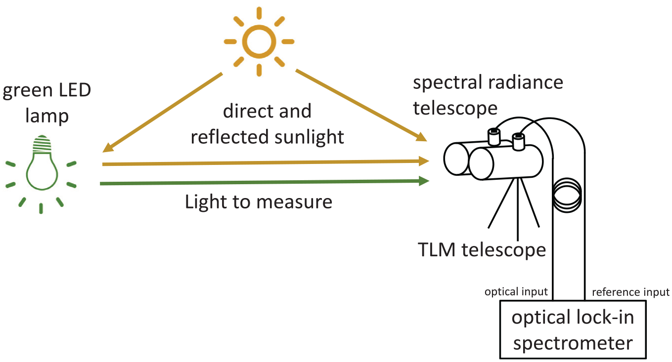
Schematic diagram of lock-in spectral radiance measurements performed under daylight
A second telescope, identical to the one used to detect TLM, was used as a collection optics for spectral radiance. The input optical fibre of the lock-in spectrometer was connected at the focus of the spectral radiance telescope where the eyepiece has been previously removed. The TLM and spectral radiance telescopes were placed at about 10 m from the LED lamp. The LED lamp was set at the minimum brightness setting (value of 2 out of 255).
After aiming the remote sensing telescope towards the LED lamp, the optical lock-in spectrometer was locked to its TLM, allowing lock-in spectral measurements to be performed in real time. A photograph of the experimental setup is shown in Figure 9. A screenshot of the user interface of the optical lock-in spectrometer showing the user settings and the three simultaneously measured spectral distributions (amplitude, phase and dc distributions) is available in Supplemental Material.
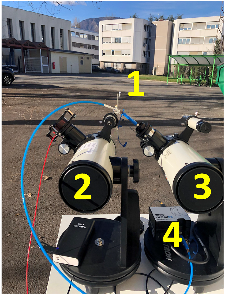
Photograph of the second experiment. (1) LED lamp; (2) TLM telescope; (3) Spectral radiance telescope; (4) Compact array spectrometer used in the lock-in instrument
The optical lock-in spectrometer, equipped with the fibre-coupled spectral radiance telescope optics, had been previously calibrated in the laboratory in terms of absolute spectral radiance using a uniform light source (output port of an integration sphere with a reference lamp) and a calibrated array spectrometer (CAS 140, Instrument Systems, Munich, Germany) fitted with a spectral radiance optical head (TOP 200, Instrument Systems, Munich, Germany).
The spectral data generated by the optical lock-in spectrometer are plotted in Figures 10 and 11, without any postprocessing. The corresponding raw data file is available in Supplemental Material. The dc spectral radiance distribution, shown in Figure 10, had a very wide spectral range, typical of daylight distributions. The spectral radiance of the green LED lamp is not detectable in this distribution. Nevertheless, the spectral amplitude distribution reveals the narrow distribution of the green LED lamp, free of any background components (Figure 11). It is interesting to note that the spectral amplitude distribution measured by lock-in detection does not require any dark correction, unlike the dc distribution. The background components are inherently eliminated by the lock-in scheme, whether they come from offsets in the CMOS array detector read-out circuit, stray light coming from the environment and entering the collection optics, or true background lights surrounding the light source of interest. In this experiment, the lowest spectral radiance value above the noise floor was about 1500 times less than the total spectral radiance. The ratio of integrated radiances (380 nm to 780 nm) between the dc signal and the amplitude signal was about 110.
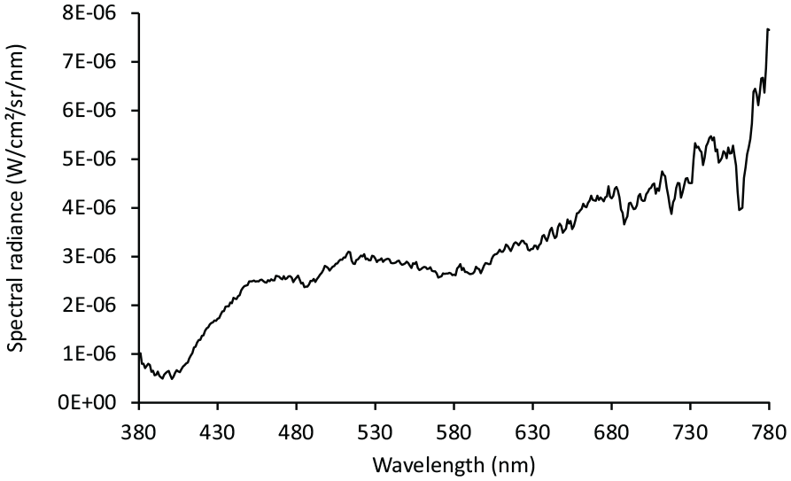
Measured dc spectral radiance distribution
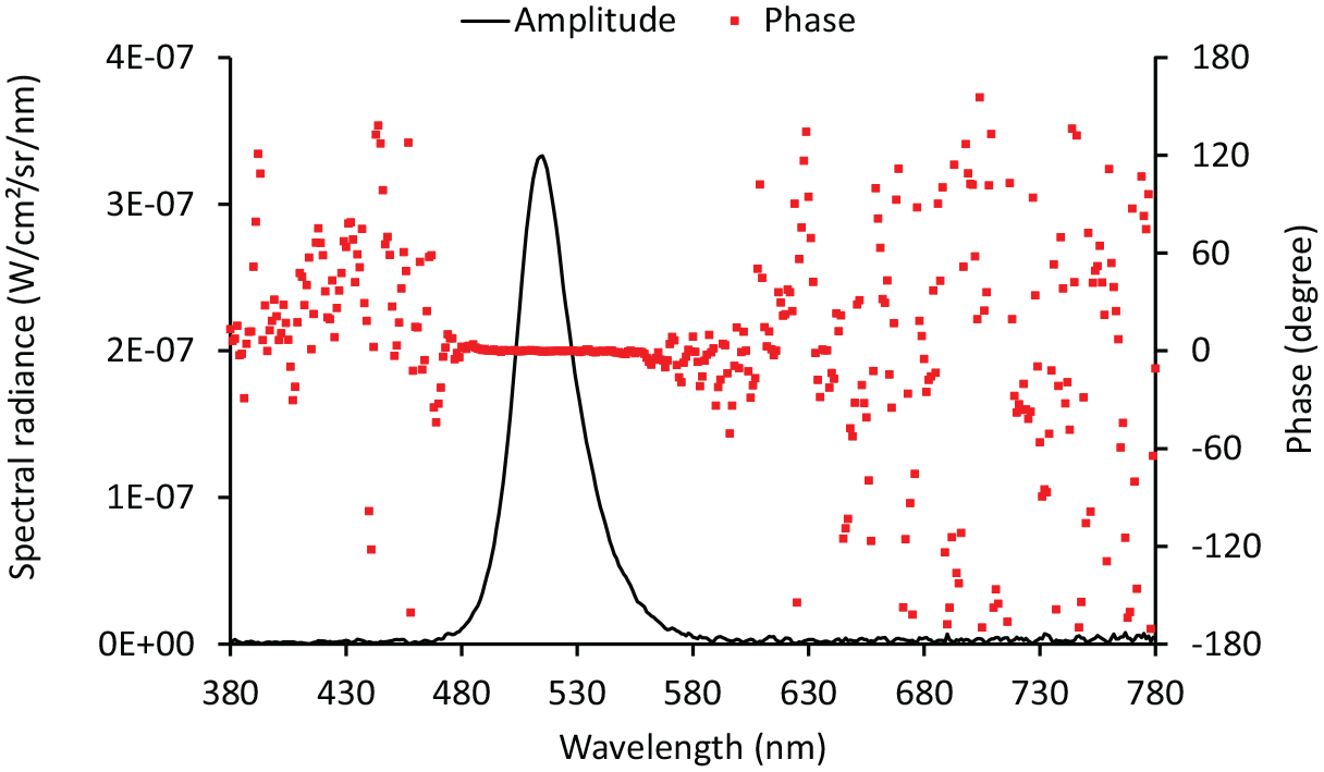
Measured amplitude (line) and phase (dots) spectral radiance distributions
The phase distribution, shown in Figure 11, is an important source of information associated with lock-in measurements. The phase values vary randomly between −180° and 180° when the amplitude is below the noise floor of the experiment. When the amplitude values are above the noise floor, the phase values indicate the temporal lag between the spectral components of the modulated spectral radiance. In our experiment, the phase was flat within ±1° across the spectral range of the green LED lamp. Therefore, there was no significant temporal lag between the spectral radiance components measured at different wavelengths.
6. Conclusions
When performing measurements of electric light sources such as luminaires, signs or displays, optical lock-in detection takes advantage of their TLM, which can be seen as the ‘electrical footprint’ of light, to extract the contribution of a given light source from the complex and noisy luminous urban environment.
An optical remote sensing device was designed to measure the TLM waveform of a light source at distances of typically a few tens of metres. This TLM remote sensing device can provide a robust reference signal to perform lock-in detection of very low levels of light attributed to a given light source.
Using the TLM remote sensing device, lock-in measurements were performed outdoors in sunny conditions to successfully measure the illuminance given by a dim LED lamp under a varying daylight illuminance that was about 500 000 times higher.
In order to apply lock-in detection to in situ spectroradiometric measurements, a four-phase optical lock-in spectrometer was designed. This new instrument is based on a compact array spectrometer acquiring sequences of quadrature spectral distributions in synch with the temporal modulation waveform of the light to measure. The performance of the optical lock-in spectrometer was demonstrated outdoors in association with the TLM remote sensing unit. This instrument was used to measure the spectral radiance distribution of an LED lamp placed under an intense background created by sunlight. The optical lock-in spectrometer successfully retrieved the spectral radiance distribution of the test lamp with an excellent rejection of the background. The minimum spectral radiance value retrieved by lock-in detection was about 1500 times smaller than the spectral radiance of the background.
Given the good performances in measuring light coming from a precise light source only, lock-in detection could be applied to facilitate the compliance testing of signs, luminaires and displays in their normal environment without turning off other light sources. The rejection of daylight also opens the opportunity to perform measurements of lighting installations and other luminous devices during daytime, thereby reducing the burden of night-time work for the involved professionals.
TLM is conserved when is light is reflected, transmitted and scattered in the environment. For this reason, an unambiguous and unique identification of electric light can be achieved by introducing a unique TLM signature, acting as a ‘tracer’. This intentional marking could be done at specific frequencies and modulation depths chosen to avoid undesired visual effects. Bearing this TLM identification mark, electric light can be traced back to its source using lock-in detection. The practical implementation of a ‘TLM tracer’ in LED luminaires could be done using a specific TLM circuit, placed between the driver and the LED module. The TLM circuit could be automatically activated for a few minutes after switch-on, or activated following an external request when measurements need to be performed.
Supplemental Material
sj-jpg-1-lrt-10.1177_14771535241266178 – Supplemental material for Untangling light in noisy luminous environments
Supplemental material, sj-jpg-1-lrt-10.1177_14771535241266178 for Untangling light in noisy luminous environments by C Martinsons and N Picard in Lighting Research & Technology
Supplemental Material
sj-txt-2-lrt-10.1177_14771535241266178 – Supplemental material for Untangling light in noisy luminous environments
Supplemental material, sj-txt-2-lrt-10.1177_14771535241266178 for Untangling light in noisy luminous environments by C Martinsons and N Picard in Lighting Research & Technology
Footnotes
Acknowledgements
The authors are grateful to the local organisation committee led by Grega Bizjak of the University of Ljubljana. A version of this work was also published in the Proceedings of the CIE 2023 Session.
Declaration of conflicting interests
The authors declared no potential conflicts of interest with respect to the research, authorship, and/or publication of this article.
Funding
The authors received no financial support for the research, authorship, and/or publication of this article.
Supplemental material
Supplemental material for this article is available online.
References
Supplementary Material
Please find the following supplemental material available below.
For Open Access articles published under a Creative Commons License, all supplemental material carries the same license as the article it is associated with.
For non-Open Access articles published, all supplemental material carries a non-exclusive license, and permission requests for re-use of supplemental material or any part of supplemental material shall be sent directly to the copyright owner as specified in the copyright notice associated with the article.