
Abstract
Traffic crashes frequently occur at intersections because drivers or pedestrians cannot properly anticipate the direction towards which other vehicles are turning. A turn signal guide lamp was developed to improve the observer’s direction judgement of turn signals, and experiments were conducted to test the effect of the guide lamp based on behavioural responses. Our experimental results demonstrated that the turning direction judgement response time was reduced when both the turn signal indicators and turn signal guide lamps were used together compared with the case when only the turn signal indicators were used. Supplementary eye-tracking data also demonstrated that the gaze point frequently stayed on the light patterns on the ground marked by the turn signal guide lamps. Additional glare evaluation using the de Boer scale showed no significant difference between the turn signal indicator with a guide lamp and the turn signal indicator alone on dry or wet road surfaces. Therefore, it is expected that the newly developed turn signal guide lamp will increase the observer’s performance of direction judgement on the turn signalling function without causing an additional glare when the observer knows the function of the guide lamp.
1. Introduction
To mitigate the risk of road traffic crashes, the signalling function of automotive exterior lighting is essential to provide other road users with information on the presence of the vehicle and/or changes in its motion. In particular, turn signal indicators provide other road users with information about the driver’s intention to change direction. Consequently, studies have been conducted with the goal of improving the visibility of front-turn signals.1-3 However, drivers and pedestrians may not see a turn signal at an intersection or corner because of occlusion by other vehicles or nearby obstacles. Consequently, many traffic crashes at intersections, and some crashes occur because other vehicle drivers or pedestrians cannot correctly detect a change of the vehicle’s driving direction. 4
Recently, a dynamic turn signal indicator was proposed and applied to some vehicles to reduce the reaction time and increase the accuracy of direction change judgements. 5 A field study by Bullough and Skinner makes it clear that there are safety-related benefits in that the visual benefits of dynamic turn signal indicators are identified at very large peripheral angles, that is, substantially larger off-axis angles. 6 Apart from changes in vehicle lighting design or function, automotive marking lights on the road surface can be used for effective communication with other drivers and pedestrians by using appropriate symbols. 7 Proper marking strategies of the matrix beam can improve visibility without creating glare and for effective communication with drivers through automotive lighting systems. 8 For instance, independent road projections on the road ahead or around a vehicle have been introduced by various manufacturers and researchers. These projections could help not only the moving vehicle’s driver, but also the drivers of other vehicles and pedestrians, to avoid various types of collisions. In a similar purpose, some studies carried out in Japan have considered the use of headlamps drawing road line and road projection lamps to prevent crashes at intersections caused by vehicles, pedestrians, motorcycles, and bicycles.9,10 The researchers focused on the brightness (luminance contrast) of road projections using different patterns, specifically rectangle and herringbone patterns, under different ambient illuminance and found a relationship between luminance contrast and ambient illuminance according to the lamp luminosity. 10
In the upcoming era of autonomous vehicles, more diverse communication lamps will be introduced and expanded in vehicle and road environments. One important aspect of autonomous vehicle performance will be its use of lighting, signalling, and other visual information to communicate with human roadway users. 11 Such measures will be driven by automobile manufacturers and the automotive lighting industry, to prioritise the safety of road users such as drivers, pedestrians, and cyclists. As a result, consumers will be able to benefit from the new automotive lighting technology.
For this reason, a turn signal guide lamp that provides marking patterns on the road to indicate the turning direction of a vehicle was developed, in addition to existing turn signal indicators. Then, we investigated the response time required for observers to judge the turning direction and the gaze points of observers in three different road scenarios to determine the effect of the guide lamps. In addition, the level of discomfort from glare from the reflected guide lamps on wet or dry road surfaces was evaluated to determine the extent to which the guide lamps cause road users to experience additional glare.
2. Preliminary work
The purpose of the turn signal guide lamps (TSGL) is to help other drivers or pedestrians easily anticipate the direction change of vehicles approaching the intersection or vehicles driving in front by adding them to the existing turn signal indicators (TS). As a first step, we analysed situations in which it might be difficult for road users to recognise information from a conventional turn signal indicator; consequently, the TSGL would be helpful in such situations.
Results of use-case analysis on the necessity of turn signal guide lamp based on the road type and traffic situation
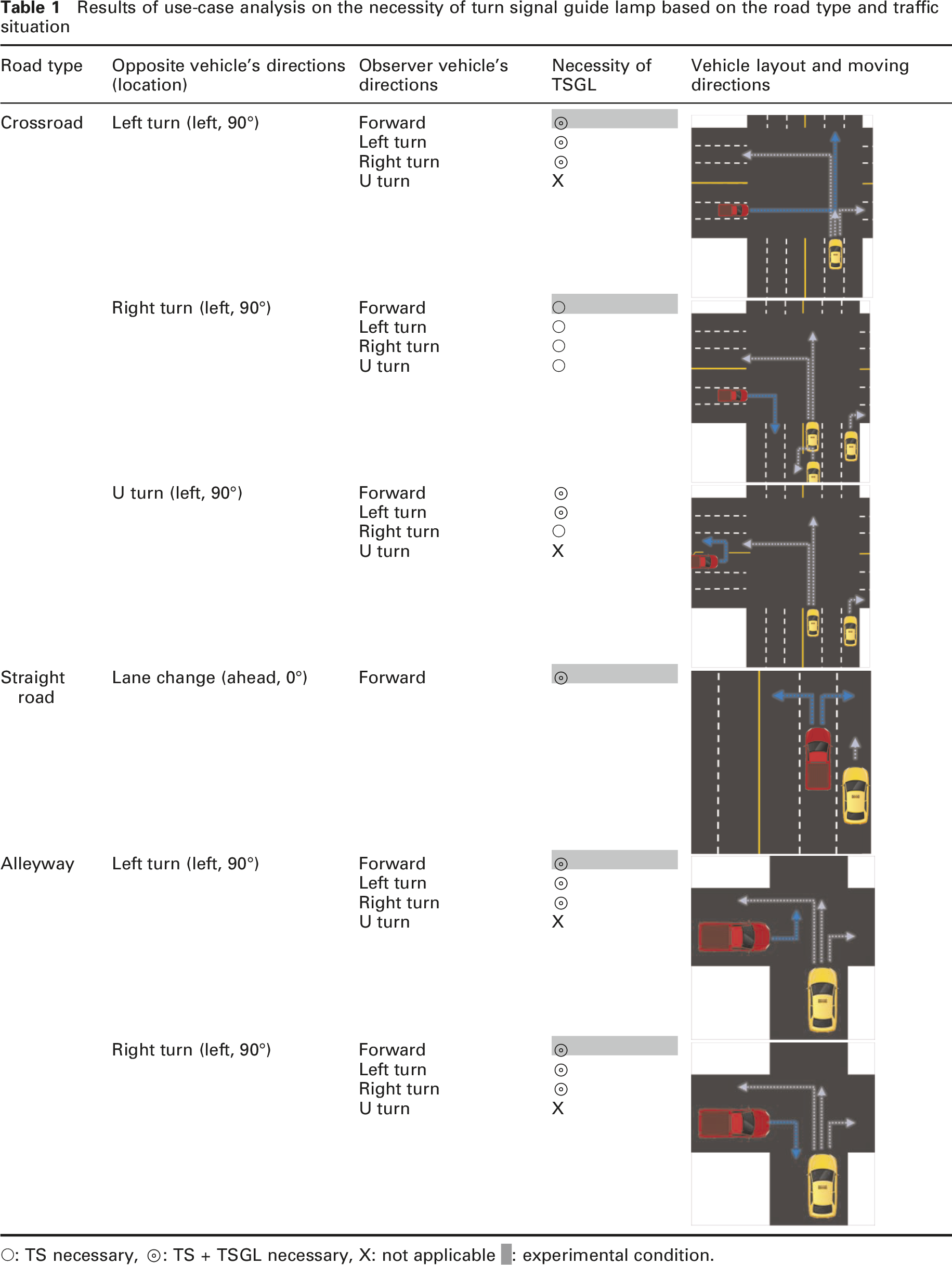
○: TS necessary, ⊚: TS + TSGL necessary, X: not applicable █: experimental condition.
Based on the directions of travel of the opposing vehicle and the observers’ vehicle, whether only a turn signal indicator is necessary (TS: ○), or turn signal indicator and turn signal guide lamp are necessary together (TS + TSGL: ⊚) are presented in each the road type with vehicle’s layout and moving directions. ‘X’ is the case that the opposite vehicle’s TSGL is not necessary to be identified. Cells shaded grey in Table 1 are the case used as the experimental condition. Depending on the road type, the cases where only TS is required and cases where TS + TSGL are required are separately indicated by considering the location and direction of the opposing and observers’ vehicles, respectively.
As shown in the table, each scenario shows the cases identified as most in need of TSGL in the combination of the opposite vehicle’s direction and the observers’ vehicle’s. When the opposite vehicle located on the left side of the intersection of a crossroad and an alleyway attempts to turn left or right, and when a preceding vehicle changes lane on a straight road, it seems that TSGL as well as TS are additionally needed. In these situations, road users sometimes cannot see the blinking of the TS located on the far side of the opposite vehicles and therefore cannot properly recognise the driver’s intention to change the direction of the vehicle. In such situations, the TSGL provides additional markings on the road surface to indicate the turning direction of the vehicle, which helps other road users to easily identify the turning direction of the vehicle.
As a result, the necessity of TSGL was found to be the highest when a vehicle on an adjacent road 90° to the left at a crossroad and alleyway intends to turn left (in the case of an alleyway, the right turn is the same because the building or wall may prevent the driver from identifying TS) and when a preceding vehicle tried to change lanes on a straight road. Based on the results of these analyses and considerations, three different experimental scenarios consisting of crossroad, lane change, and alleyway were determined.
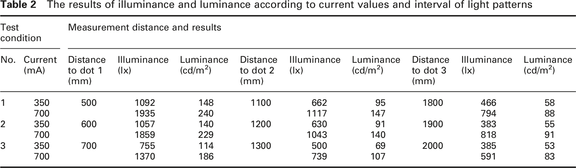
The TSGL used in this study was not implemented by the advanced lighting system (ALS) that is usually based on the matrix LED headlamp system, but was used as a standalone form added next to existing headlamps to operate simultaneously with TS. In developing TSGL, we evaluated the noticeability, luminance, and illuminance of the marking light pattern in different directions, marking light intervals, and intensities. The lane interval and width of the vehicle were also considered during prototype development. Amber and white LEDs were tested to assess how well the marking patterns were noticeable and identifiable. Figure 1 shows examples of the parameters evaluated during the development of the prototype, and Table 2 presents the measurement results of illuminance and luminance according to current (mA) values while changing the distance of the centre of the first dot (dot 1) pattern from 500 mm to 700 mm while maintaining the intervals between dot patterns. Examples of evaluated parameters The results of illuminance and luminance according to current values and interval of light patterns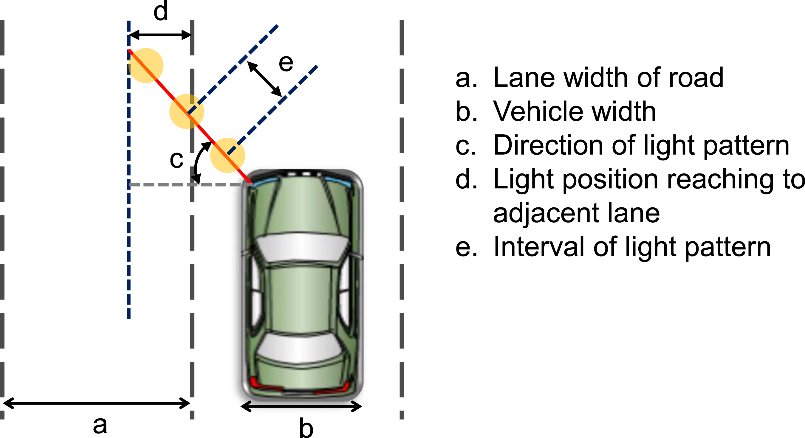
In summary, the results of the preliminary work predicted that TSGL would be most needed when an approaching vehicle at an intersection or alley intends to turn left or right, and it is expected to provide useful information when a preceding vehicle changes lane on a straight road. Therefore, intersections, lane changes, and alleyways were finally selected as scenarios for the experiment. For such a scenario, a TSGL prototype was developed that projects amber dot patterns onto the road surface, distinct from the headlamps and operating in synchronisation with the turn signals.
3. Method
3.1. Experimental setup
The overall laboratory experimental setup is shown in Figure 2. A lamp post was used to control the ambient light conditions during the experiment. Assuming the driving in city, the average illuminance on the road surface measured at the observer position of three scenarios was about 10 lx. If necessary, the illuminance of the road area could be changed by adjusting the height of the street lighting. A model vehicle was used in the experiment, and was a similar size to a real executive sedan. The frames were assembled to present a vehicle shape covered by a black matte PVC tarpaulin sheet except for front lamp modules, including head lamps, turn signal indicators, and turn signal guide lamps. Two TSGLs were installed just inside the TS at a height of 750 mm from the road surface, and 3 rectangular patterns were projected on the road surface at an angle of 30° from the front to the left and right. They were synchronised with the TSs, and the headlamps were kept low beam on. All lamps were controlled by a computer program according to the experimental protocol. Wheels attached to the vehicle model made it easy to move according to the experimental scenarios, and the lamp height and aim could be adjusted. The floor of the laboratory was covered with a 6 m x 12 m asphalt shingle mat with a texture similar to the road surface, and lane markings were marked with a 100 mm x 600 mm acrylic plate with a white reflective sheet. The experimental laboratory was located in an underground dark room of dimensions 20 m length, 10 m width of empty floor space and 10 m high concrete walls. Laboratory experimental setup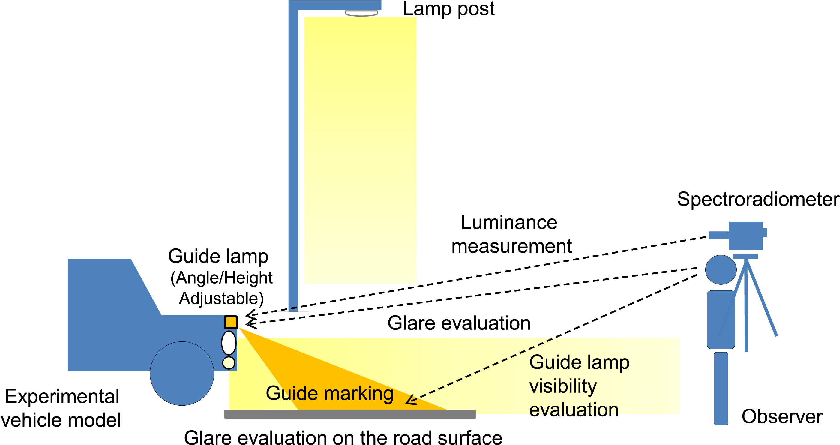
3.2. Scenario
The experimental scenarios for the behavioural response experiments were crossroad, lane change, and alleyway. In the crossroad scenario, when the opposite vehicle located on the left side of the intersection of a crossroad to turn left or right, my vehicle is waiting for moving forward. The right TS of the opposite vehicle is visible, but the left TS is not directly visible to the observer who participates in the experiment. The observer’s location is corresponding to the driver’s location or other road users.
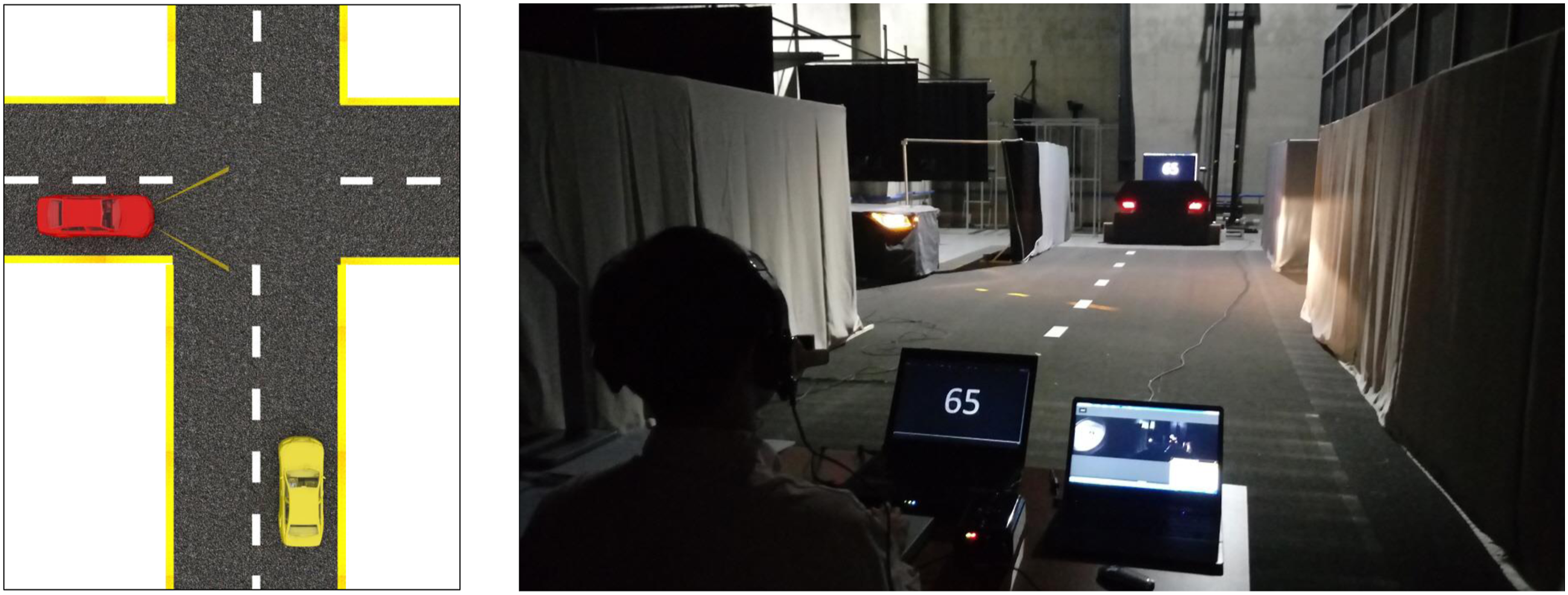
In the lane change scenario, a proceeding vehicle tries to change lanes on a straight road. The proceeding vehicle can change lane to the left or the right. Similar to the first scenario, the right TS is visible, but the left TS is not directly visible to the observer. Also, the vehicle’s relative distance and the angle of the TS were changed because the vehicle was facing forward.
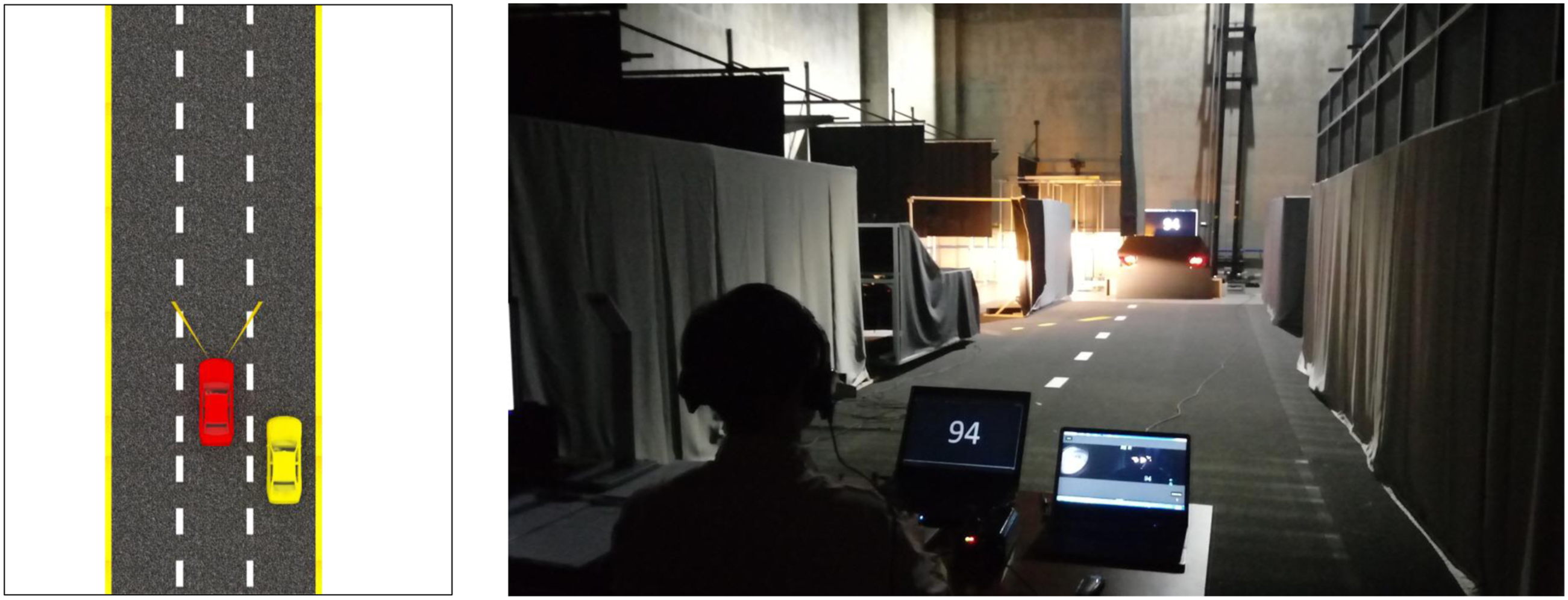
Direct visibility of the turn signal indicator (TS) and turn signal guide lamp (TSGL) to the observer in each experimental scenario
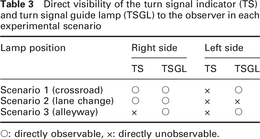
○: directly observable, ×: directly unobservable.
Experimental setup for the crossroad scenario
Experimental setup for the lane change scenario
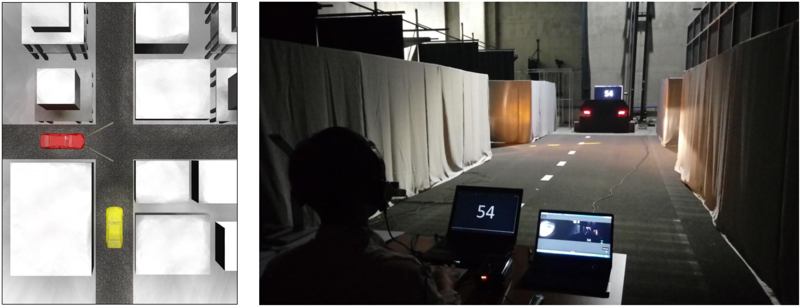
Experimental setup for the alleyway scenario
3.3. Hypotheses
The usefulness of the TSGL function was investigated using the developed prototype and experimental setup. Three experimental scenarios that are expected to be needed by road users were prepared for the behavioural experiment on the observer’s performance of direction judgement. The experimental setup was changed according to the selected scenario.
The hypotheses of this study were as follows. First, when using the TSGL and the existing TS simultaneously, an observer would judge the intended direction change of an opposite vehicle faster than when using only the existing TS. Second, the direction judgement response time will be faster when the TSGL located on the far side, where the TS is not easily visible to the observer, is turned on. Third, such a direction judgement response time would be faster in young (university student) group than in middle-aged group. Therefore, the experimental design was a repeated-measures mixed design, and the independent variables were the use of TSGL, the position of TSGL, and the age of the observer group. The dependent variable was the direction judgement response time.
3.4. Participants
Thirty undergraduate and graduate students from Yeungnam University (male: 19, female: 11, average age: 25.3 years) and 30 middle-aged people in their 40s and 50s (male: 17, female: 13, average age: 50.6 years) recruited from inside and outside the university participated in the experiment. Those with corrected visual acuity of 0.7 or higher were recruited as participants since those who want to get a driver’s license in Korea must have a corrected visual acuity of 0.7 or higher, and glasses were allowed to be worn during the experiment.
3.5. Apparatus and stimuli
A prototype vehicle model, including headlamps, TSs, and TSGLs, was used for the experiment. The headlamps were always on, and when a signal was given, the left or right TS and the TSGL were turned on simultaneously. At that time, a yellow-dotted light marking pattern with a luminous intensity of 8000 cd/m2 was emitted to the road surface at an angle of 30° to the outside. To prevent the participants’ attention or gaze direction from pre-shifting to the vehicle model from the front in anticipation of the TS or TSGL being turned on, a TV display was placed in the far front of the floor (about 14 m), and a two-digit random number was presented every 2 seconds. Then, the participants had to read the numbers aloud. Additionally, there were two rear combination lamps that were used to represent passenger cars located just below the TV display. The left or right TS flashed randomly, and participants were asked to determine which side was blinking. Depending on the purpose of the experiment, except for the road surface, the road areas were blocked with a 2-m-high grey cloth walls.
E-prime 2.0 Professional software (Psychology Software Tools Inc.) was used to control the lamps’ on/off time and record the participants’ behavioural response times. A push button box, RB-840 Response Pad (Cedrus Co.), was used to measure the response time required for participants to identify left or right TS with or without the TSGL. A headset eye tracker, EyeGuide® Mobile Tracker (EyeGuide Inc.), was used to track and analyse the participants’ gaze points during the experiment. A scene camera with a 90° field of view in combination with eye tracking provided the gaze point in the scene during the experiments. A Spectrometer CS-2000 and Image Analyser CA-2000 (Konica-Minolta, Inc.) were also used to measure the luminance and spectral distribution of the illumination.
3.6. Procedure
Before entering the experiment, the experimenter explained the function and role of the guide lamp to the participants and showed the marking pattern of the road surface. And through practice session, the participants checked the condition where only the TS was turned on and the condition where the TS and TSGL were turned on together, and they practiced after a sufficient explanation about the task from the experimenter.
An experimental trial consists of the following. As a preparatory action, the participant reads aloud a two-digit number presented every 2 seconds on the TV screen located in front, and when either TS of the left and right rare combination at the bottom starts to blink, identify it and press the corresponding button in the response box. Next, the main experimental task required of the participants was to identify the TS or the marking dot lines of the TSGL and judge the expected turning direction of the experimental vehicle as soon as possible. When a participant determined the turning direction of the vehicle, they had to press the left or right button on the response box. We mainly measured the time taken to judge the turning direction from the moment the lamps were turned on, and additionally recorded the eye gaze points of the participants.
Participants were located at specified positions. In the case of crossroad and alleyway scenarios, the location was a point where the vehicle model can be seen at a certain distance on the road orthogonal to the right of the vehicle model. The distance from the right-side TS of the vehicle model to participants in the scenarios was approximately 7 m. In the case of lane change scenario, it was the location corresponding to the driver’s position of the vehicle following at a certain distance from the rear right. The distance from the right-side TS of the vehicle model to participants in the scenario was about 6 m. The participants could see the right side TS directly only in the crossroad situation. Otherwise, they could see the reflected light of the TS on the wall and road surfaces. However, they were able to see the yellow-dotted marking lines projected by the TSGLs in all cases except when the left TSGL was lit in the lane change scenario.
4. Results
The experimental data were analysed using ANOVA and t-test using IBM SPSS Statistics (ver. 25). Lamp type (TS vs. TS+TSGL) and lamp position (left vs. right) were within-subjects variables, and age group (young group vs. middle-aged group) was between-subjects variable.
4.1 Crossroad scenario
The result of the ANOVA analysis on the crossroad scenario showed that the TSGL significantly reduced the judgement response time on the turning direction. Figure 6 shows the response time required to judge the turning directions according to the lamp type, age group and position when the participant observed either the TS or the TS+TSGL. Result of turning direction judgement response time in the crossroad scenario. (a) The mean RT for TS and TS+GL in different age groups, (b) the mean RT for left and right lamps in different age groups, and (c) the mean RT for TS and TS+GL in different lamp positions.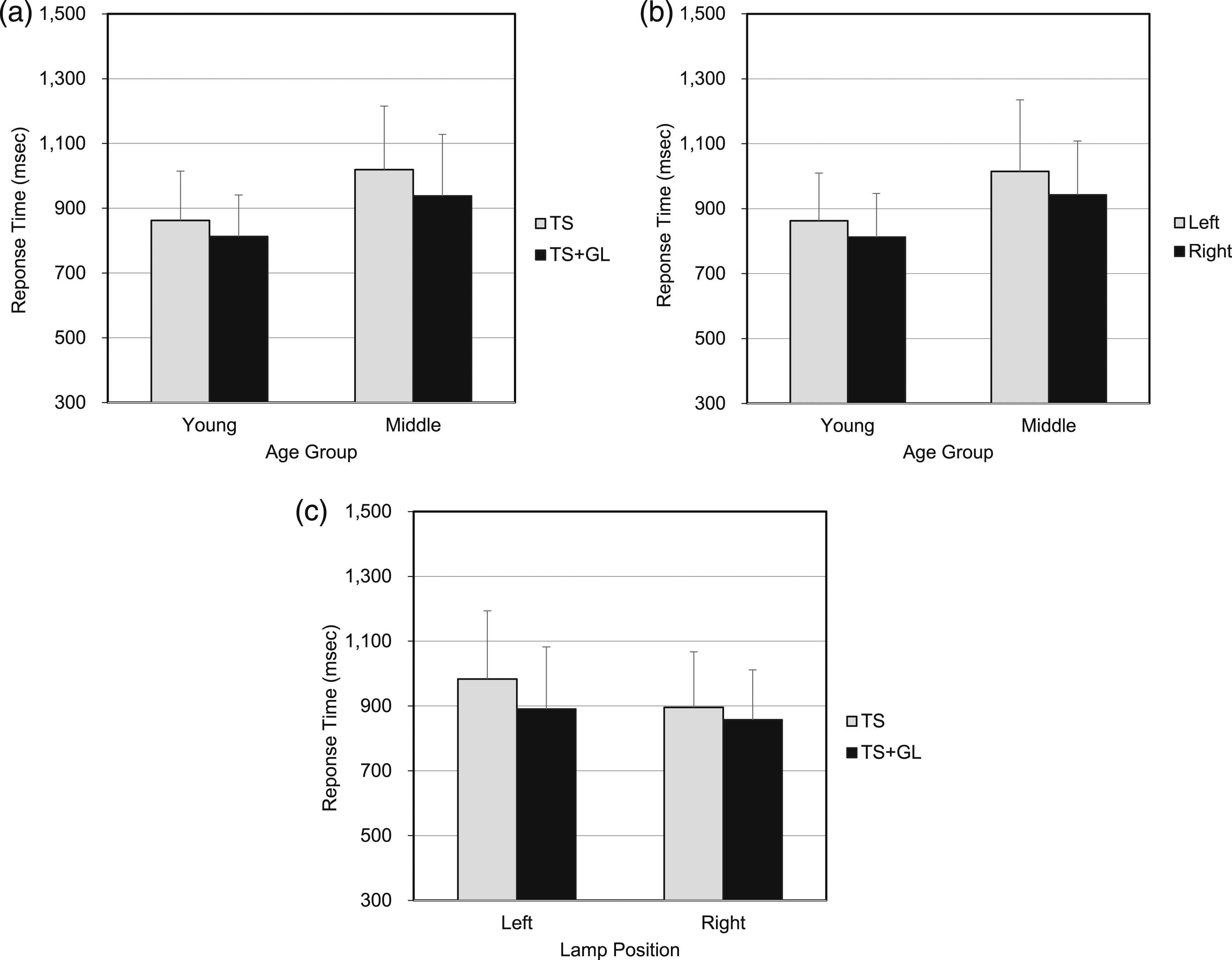
There was a main effect of lamp type [F(1,58)=39.893, p=.000], but no interaction effect between lamp type and age group [F(1,58)=2.223, p=.141], as shown Figure 6(a). Also, there was a main effect of lamp position [F(1,58)=34.398, p=.000], but no interaction effect between lamp position and age group [F(1,58)=1.142, p=.290], as shown in Figure 6(b). In the other hand, there was an interaction effect between lamp type and lamp position [F(1,58)=8.019, p=.006], but the interaction among lamp type, lamp position, and age group was not found [F(1,58)=0.035, p=.853]. When a paired t-test was performed to compare the response times of each lamp type and lamp position condition, the response to the TS+TSGL was significantly faster than the response to the TS only. This was obvious on the left side [t(59)=5.429, p=.000] compared to the right side [t(59)=3.669, p=.001], as shown in Figure 6(c). Response time to the both lamp types on the right side was faster to the lamp types on the left side [TS: t(59)=5.604, p=.000; TS+TSGL: t(59)=2.747, p=.008].
In general, the response time in TS + TSGL condition was faster than that in TS condition, probably because the marking lights of the guide lamp helped the judgement response. The response time of the young-aged group was faster than that of the middle-aged group, probably because they were superior in perceptual judgement and motor control. The reason that the difference was greater on the left side may be because the left-side TS could not be directly seen from the viewpoint of participants, but the marking dots of the left TSGL on the ground could be seen directly.
4.2. Lane change scenario
The results of ANOVA analysis of the lane change scenario showed that the TSGL significantly reduced the judgement response time on the turning direction, particularly on the right side. There was a main effect of lamp type [F(1,58)=63.963, p=.000], but no interaction effect between lamp type and age group [F(1,58)=0.006, p=.937]. Although it was close to the significant level, but there was no main effect of lamp position [F(1,58)=3.058, p=.086], and no interaction effect between lamp position and age group [F(1,58)=2.319, p=.133]. In the other hand, there was an interaction effect between lamp type and lamp position [F(1,58)=41.230, p=.000], but the interaction among lamp type, lamp position, and age group was not found [F(1,58)=0.065, p=.799]. When a paired t-test was performed to compare the response times of each lamp type and lamp position condition, the response to the TS+TSGL was significantly faster than the response to the TS only, particularly in the right side of the vehicle [t(59)=8.164, p=.000 vs. t(59=0.339, p=.736).
Since the marking dot line projected by the TSGL on the left side road surface could not be seen at the observer’s position, it seems that there was no difference in the response time between the TS and TS+TSGL conditions on the left side, that is, opposite from the observer. Therefore, on the left side of the preceding vehicle, the difference in response time according to the lamp type was not large. Figure 7 shows the response time needed to judge the turning directions according to the lamp type (a), age group (b), and position (c) when the participant observed the TS or the TS+TSGL. Result of turning direction judgement response time in the lane change scenario. (a) The mean RT for TS and TS+GL in different age groups, (b) the mean RT for left and right lamps in different age groups, and (c) the mean RT for TS and TS+GL in different lamp positions.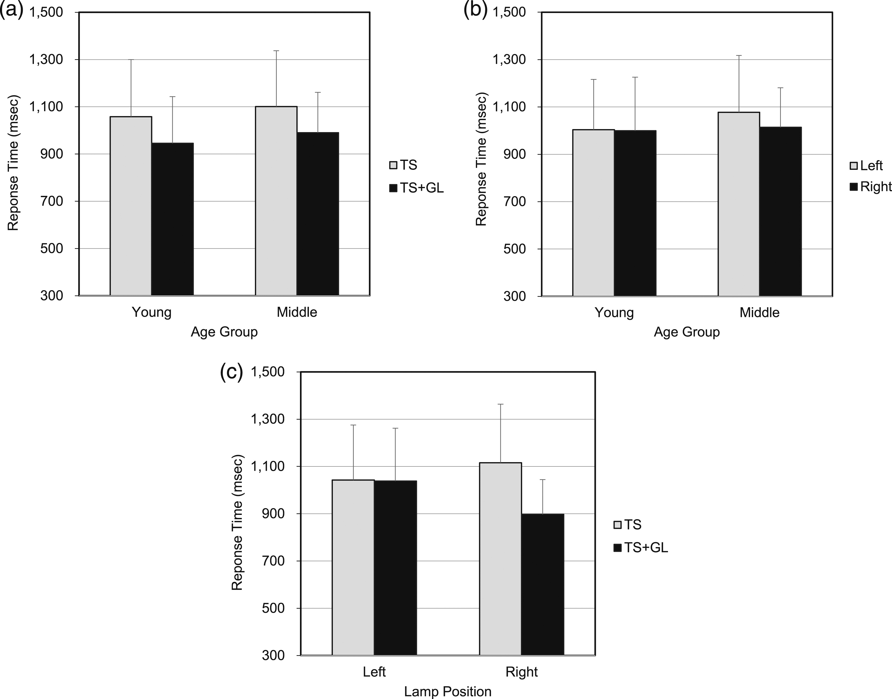
4.3. Alleyway scenario
The results of ANOVA analysis of the alleyway scenario showed that the TSGL significantly reduced the judgement response time on the turning direction. There was a main effect of lamp type [F(1,58)=89.988, p=.000] and an interaction effect between lamp type and age group [F(1,58)=10.421, p=.002]. Also, there was a main effect of lamp position [F(1,58)=7.564, p=.008], but no interaction effect between lamp position and age group [F(1,58)=0.003, p=.955]. In the other hand, there was an interaction effect between lamp type and lamp position [F(1,58)=41.770, p=.000], but the interaction among lamp type, lamp position, and age group was not found [F(1,58)=2.614, p=.111]. When a paired t-test was performed to compare the response times of each lamp type and lamp position condition, the response to the TS+TSGL was significantly faster than the response to the TS only. The difference was bigger on the left side [t(59)=10.175, p=.000] than on the right side [t(59)=3.379, p=.001].
As shown in the interaction effect, there was a significant difference between the TS and TS+TSGL conditions in the middle-aged group, suggesting that TSGL helped the direction judgement response more in the middle-aged group than in the younger group. The difference in response time as a function of lamp type was greater on the right side. It was because participants could not see the TS on either side but could observe the reflected light of the TS on the left side wall. However, they could not detect any direct or reflected light of the TS on the right side. Figure 8 shows the response time required to judge the turning directions according to the lamp type when the participants observed the TS or TS+TSGL. Result of turning direction judgement response time in the alleyway scenario. (a) The mean RT for TS and TS+GL in different age groups, (b) the mean RT for left and right lamps in different age groups, and (c) the mean RT for TS and TS+GL in different lamp positions.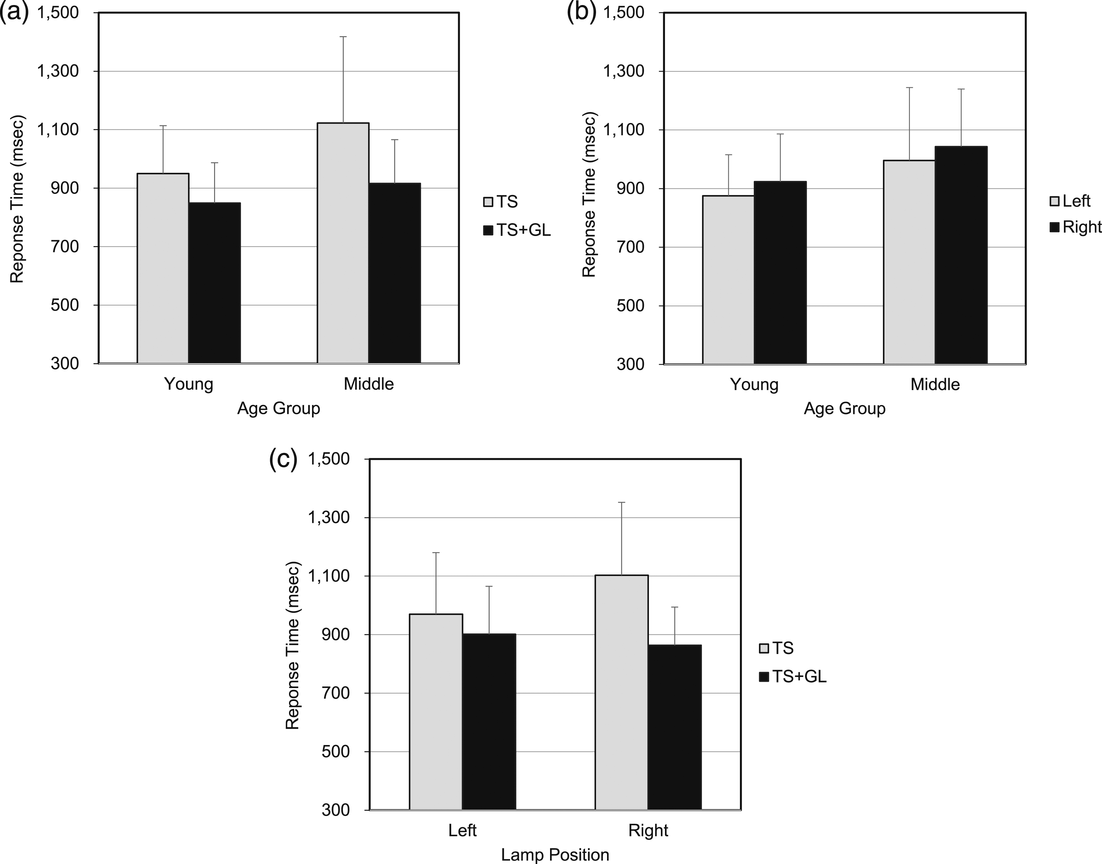
5. Discussion
The results of this study show that TSGL can improve the turn signal function of automotive lighting, may result in less vehicle crashes. The results of this study did not directly show whether drivers or pedestrians understand the meaning of the additional signal by the guide lamp without any cognitive cost. However, since the guide lamp was turned on and off in synchronisation with the turn signal indicator, participants may be easy to understand the guide lamp function as an additional signal without ambiguity. Moreover, our experiment showed that projecting a dotted light pattern on the road surface was very useful in situations where the road users could not directly see the TSs such as when the opposite vehicle was coming from alleyways.
In the crossroad scenario, both the left and right TSGLs showed a significant improvement in response time, and the left TSGL showed a greater effect. More specifically, the left TSGL reduced the response time by 93 msec and the right one reduced it by 39 msec. This corresponds to 9.5% and 4.3% of the response times obtained from TS without TSGL, respectively. In the lane change scenario, the left TSGL had no effect, while the right TSGL significantly improved the response time. The right TSGL resulted in a reduction in the response time of 218 msec, which was 19.5% of the original response time. In the alleyway scenario, both the left and right TSGLs showed a significant improvement in response speed, and the effect was relatively greater on the right side than on the left side. The left TSGL decreased the response time by 69 msec, and the right TSGL decreased it by 239 msec. Such decreases correspond to 7.1% and 21.7% of the response times obtained from TS without TSGL, respectively.
In order to confirm whether TSGL actually affected the response time of the participants, we recorded the gaze movements of some participants with eye tracker while we were performing the experimental task. Unlike when only TS was used, when TS and TSGL were used together, the gaze of the participants was frequently moved to the road surface on which the yellow marking dots projected by the TSGL. In that case, the response time of the participants was also fast.
When TSGL is used, there may be concerns about glare due to road reflection. Particularly, discomforting glare by LED headlamps is an important issue affecting the driver’s safety on the road. 12 Therefore, in order to evaluate the glare effect caused by TSGL, we asked some participants to evaluate the glare level at the location where the maximum intensity of the reflected guide light pattern reached their eyes. For the evaluation, we used dry and wet road surface and the de Bore discomfort glare score, in which the highest score of 9 is ‘Very Satisfactory’ and the lowest score of 1 is ‘Unbearable’. This means that the low the score, the greater the glare. The result from 14 participants who compared the TS glare and TS+TSGL glare showed that the average discomfort glare scores were 4.7 and 5, respectively. Consequently, the use of TSGL seems to increase the glare slightly, but it does not deviate significantly from the ‘Just Acceptable’ category of the scale. When the glares from dry and wet road surfaces were compared, the de Boer discomfort scores were the same regardless of whether the TSGL was used. Therefore, it is assumed that the TSGL does not increase the level of glare experienced by pedestrians or other drivers even under rainy weather conditions.
When the response times of the two age groups were compared in three different experimental scenarios, the overall performance of the middle-aged group was slower than that of the student group. Particularly, when the RT difference between TS and TS+TSGL was compared, it was bigger in the middle-aged group than in the young-aged group. This suggests that the TSGL would be more helpful to the middle-aged group when they have to judge the turning direction of the opposite vehicles on the road.
If there are multiple turn signal guide lamps projected on the road surface and if road participants do not understand the function of turn signal guide lamp, the turn signal guide lamps may cause causes ambiguity and additional cognitive load. However, this study is focused on single turn signal guide lamp pair synchronised with turn signal indicator and participants understood the function of turn signal guide lamp in advance, there may be few effects of confusion or additional cognitive load.
This study was implemented in the laboratory trying to simulate real driving situation: relative vehicle distance and orientation considering real road condition, artificial distraction by speaking numbers loudly, and so on. The study, however, was executed in the laboratory environment setup without any actual movement of the vehicle, and the experiment results could be different from real driving situation. Actually, we found that some of our experiment results could be affected by certain indirect reflection of turn signal indicator or turn signal guide lamps from the wall or other indoor facilities, which was not exist if real open road situation.
Although the experiment was conducted with 30 participants by age group, the data under some experimental conditions did not meet the normality condition required for parametric statistical analysis. However, in order to effectively present the research data, the results of parametric statistical tests based on the mean and standard deviation of the response time are presented. To confirm the validity of the analysis results, Wilcoxon Signed Ranks Test, a non-parametric test method, was conducted. The results showed a similar trend to the results of the parametric statistical method described in this paper.
6. Conclusion
This study shows that the use of TSGL with TS significantly improved the response times of participants who had to anticipate the turning direction of an observed vehicle. This improvement in the response time of direction judgement caused by the use of TSGL was greater in the middle-aged group than in the young-aged group.
The results of this study are expected to contribute to safety improvement by helping drivers or pedestrians quickly determine the presence or direction of other vehicles when TSGL is used in combination with TS if there are no ambiguity and confusion. However, since this study was conducted in a laboratory using a limited number of methods and participants, care should be taken in interpreting and generalising the results. In addition, this study did not directly confirm whether drivers or pedestrians can intuitively understand the meaning of additional signals by guide lamps well and use them without ambiguity or confusion without cognitive costs.
In the future work, it may need to estimate distraction, confusion or ambiguities of the guide lamp when there are simultaneously multiple TSGLs or similar projection lights on the road. It may also need to evaluate how people interpret the function of the TSGL if they observe the TSGL with no information provided in advance. Also, it is necessary to further investigate the glare level according to the luminance of the TSGL at different vertical angles and ambient brightness conditions. If possible, it is necessary to obtain more sufficient empirical data through repeated experiments and field tests.
One encouraging thing is that more studies on specific application methods of road projection or communication lamp have been recently attempted and showed the possibilities of the TSGL.9,10,13,14 If follow-up studies on the application of TSGL sufficiently prove that it contributes to driver’s road information processing and, in particular, the safety of the elderly, it will be of practical help to road users by revising related regulations and applying TSGL to actual vehicles.
Footnotes
Declaration of conflicting interests
The authors declared no potential conflicts of interest with respect to the research, authorship, and/or publication of this article.
Funding
The authors disclosed receipt of the following financial support for the research, authorship, and/or publication of this article: This research was funded by SL Corporation and partially supported by the Basic Science Research Program through the National Research Foundation of Korea (NRF) funded by the Ministry of Education (NRF-2020R111A3062042).