
Abstract
Transmissibility function analysis refers to the evaluation of the ratio between the spectra of two different outputs of a system and has been widely used for the detection and localization of damage in linear structural systems. In this article, a new transmissibility function analysis methodology is proposed to detect and localize damage with nonlinear features in multidegree-of-freedom (MDOF) structural systems. The methodology assumes the MDOF systems are subject to a general input with only the frequency range known a priori so is applicable to address damage detection and location issues for a wide range of engineering structures and systems. This methodology is derived based on the concept of nonlinear output frequency response functions (NOFRFs) and the concept of transmissibility of nonlinear systems introduced based on the NOFRFs. The transmissibility function analysis over output frequencies contributed by system nonlinearities is exploited to detect and localize damage with nonlinear features in MDOF structural systems. Both numerical simulations and experimental studies on a cracked beam structure in the laboratory have been conducted. The results verify the effectiveness and demonstrate the potential applications of the proposed methodology in the detection and localization of damage in practical engineering structures.
Keywords
Introduction
Infrastructures and mechanical systems inevitably suffer damage along with aging, which has drawn significant research interest in localization and quantification of damage in structural systems. Vibration-based damage identification has been developed by many researchers.1–6 This is because changes in physical structures naturally induce changes in vibration-related system properties such as for example, natural frequency, modal damping, and mode shape. Vibration-based damage identification methods include methods that evaluate changes in system natural frequency, changes in mode shape, changes in frequency response function, and changes in transmissibility functions. Among these, the evaluation of changes in transmissibility functions is preferable since transmissibility functions not only have better sensitivity to damage but also require no prior information on loadings on linear dynamic systems due to the removal of input loading information by definition. 7
Transmissibility function is traditionally defined as the ratio between the output spectra of two degrees of freedom in an MDOF system and was originally applied for structural damage identification in Chen et al. 8 Recently, many transmissibility function-based damage indicators have been proposed,9–12 showing that the transmissibility-based methodologies outperform the classical frequency response function (FRF) in terms of the sensitivity of damage identification. In Johnson and Adams 7 the significance of poles and zeros for the localization of damage in dynamic systems has been investigated and then its sensitivity analysis has been studied on a 3 DOF system. More recently, it has been proved that the transmissibility function converges to the mode shape ratio when frequency bandwidth is restricted to the system’s poles, and damage could be identified according to the changes in the transmissibility functions around these poles. 9 Based on this principle, a method to detect the existence and quantify the severity of damage has been proposed 10 but the method cannot be used to localize damage. In Cheng et al., 11 the strain transmissibility measured using distributed fiber optics is used for damage localization, showing that the transmissibility of strain is more sensitive to local damage than the transmissibility of displacement and the transmissibility of acceleration. A transmissibility-based analytical methodology has been developed to localize damage induced by mass and stiffness changes in MDOF mass–spring–damper systems. 12
However, existing transmissibility function analysis mainly focuses on the identification of linear damage including, for example, changes in mass and stiffness, and is unable to detect changes induced by nonlinear damage. 13 Damage makes engineering structures behave nonlinearly in many scenarios, for example, breathing cracks (bilinear stiffness), postbuckled structures (duffing nonlinearity), and rattling joints (systems with discontinuity characteristics) are typical nonlinear damage in MDOF structural systems.14–17 Therefore, the study of nonlinear damage identification is of great practical importance.
Recently, the concept of transmissibility of nonlinear systems was proposed by Lang et al., 18 which is defined as the ratio of nonlinear output frequency response functions (NOFRFs) between two measurement points. The NOFRFs are a relatively new concept and a powerful and effective tool for the analysis of nonlinear systems in the frequency domain. 19 On the basis of the concept of transmissibility of nonlinear systems, Zhao et al. 20 developed a technique for the identification of nonlinear damage in MDOF structural systems. In this technique, an MDOF system is assumed to be subject to a harmonic input and the damage detection is performed by evaluating the transmissibility functions of the system responses at super-harmonics. However, harmonic input excitations can only be implemented in purposely designed test campaigns. Consequently, the harmonic input-based technique is not applicable to the identification of damage in real infrastructures such as, for example, long-span bridges where only structural responses to more complicated ambient loading excitations are available for analysis. 21
In the present study, a new methodology for the detection and localization of damage with nonlinear features is developed for MDOF structural systems. The two key novelties of this article are (1) extending the existing NOFRF-based transmissibility to more general input cases. General input excitations can cover various ambient loading inputs, including, for example, loadings from cars running on a long-span bridge and impacts of winds on tower structures. The new methodology is derived based on the properties of the transmissibility of nonlinear systems within and outside the frequency ranges of system inputs, and its implementation can be straightforwardly achieved by evaluating conventional transmissibility functions over output frequencies contributed by system nonlinearities; (2) formulating a new damage indicator to detect and locate the nonlinear components. Both numerical simulations and experimental studies are conducted to verify the effectiveness and demonstrate potential applications of the proposed methodology in the detection and localization of damage in practical engineering structures.
This article is structured as follows: In section “Transmissibility of Nonlinear Systems,” the concept of transmissibility of nonlinear systems is introduced. Section “Transmissibility function of nonlinear MDOF structural systems under general inputs,” is concerned with the revelation of significant properties of the transmissibility of nonlinear systems. These properties lead to some valuable features with the transmissibility functions of MDOF systems under general inputs and enable the derivation of a novel methodology for detecting and localizing nonlinear components in MDOF structural systems. The procedure of the new methodology is summarized in section “Damage detection and localization methodology.” Numerical simulations and experimental studies are conducted in sections “Simulation study,” and “Experimental study,” respectively. Conclusions are finally reached in section “Conclusion.”
Transmissibility of nonlinear systems
The Volterra series representation of nonlinear systems
Nonlinear systems that are stable at zero equilibrium can be expressed using a Volterra series as 22
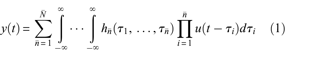
where
The NOFRFs of nonlinear systems
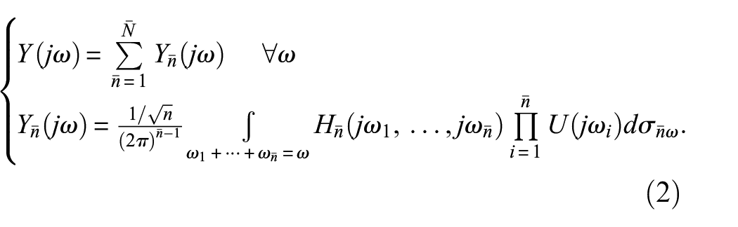
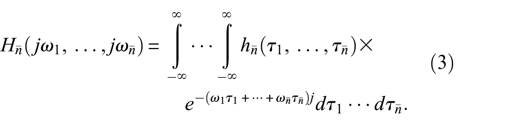
The nonlinear output frequency response functions (NOFRFs) are a concept introduced in 2005 (Lang and Billings 23 ) as a new extension of linear FRF to nonlinear cases, and defined as
under the condition of
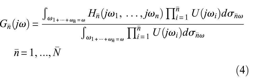
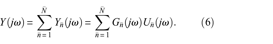
As stated in Equation (4), one of the main advantages of NOFRFs is their one-dimensional nature. This characteristic has led to suggestions of replacing the multidimensional GFRFs to simplify the frequency analysis of nonlinear systems. 23 Equations (2) and (4) reveal that the output spectrum of system Equation (1) can be effectively characterized using NOFRFs, as demonstrated in Equation (6). Notably, this representation is analogous to the output spectrum description in linear systems,
The NOFRFs of single input multiple outputs nonlinear systems
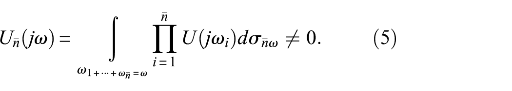
For single input multiple outputs (SIMO) nonlinear systems with
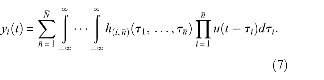
In Equation (7),
The NOFRFs associated with the ith output of the system can be defined as
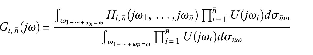

The spectrum of the ith output can then be represented using the NOFRFs as
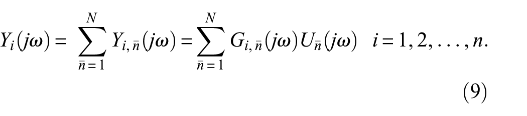
The transmissibility of nonlinear systems
Transmissibility in SIMO linear systems refers to the ratio between the spectra of two distinct outputs, which is equivalent to the ratio of two system FRFs evaluated at the corresponding output points.7,10 The concept of transmissibility in SIMO nonlinear systems was initially presented in Peng et al., 19 where it is described as the ratio of system NOFRFs between two different outputs, given by
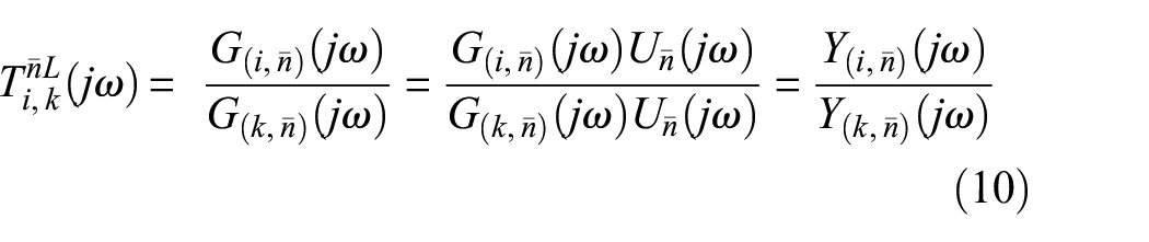
where
It is obvious the transmissibility of nonlinear systems Equation (10) reduces to the traditional transmissibility of linear systems when
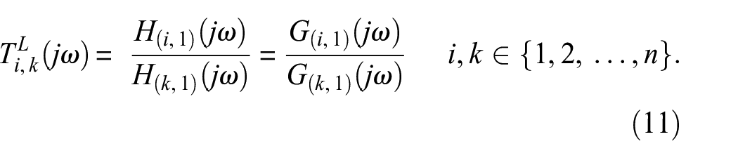
An important feature of NOFRFs is their independence from changes in the system input by a constant, as noted in Peng et al. 19 This property ensures that the transmissibility of nonlinear systems, as defined in Equation (11), remains insensitive to such changes. This attribute is analogous to the property of transmissibility in linear systems.
Transmissibility function of nonlinear MDOF structural systems undergeneral inputs
The properties of transmissibility in nonlinear MDOF structural systems under harmonic inputs were investigated by Peng et al., 19 this does not account for interactions between input components at different frequencies in nonlinear dynamic systems. When the loading inputs are multitone, band-limited, or random signals, the system dynamics become more complicated compared to the single harmonic case due to the interactions between input components. Furthermore, as harmonic inputs are not representative of ambient loadings in most practical operational conditions, the applicability of transmissibility analysis for damage detection and localization must be expanded. Therefore, in this section, we broaden the scope of our investigation to encompass the transmissibility function of nonlinear MDOF structural systems under general inputs, with the goal of enhancing the practicality of our findings.
Nonlinear MDOF structural systems
A wide class of linear MDOF structural systems can be described by

where
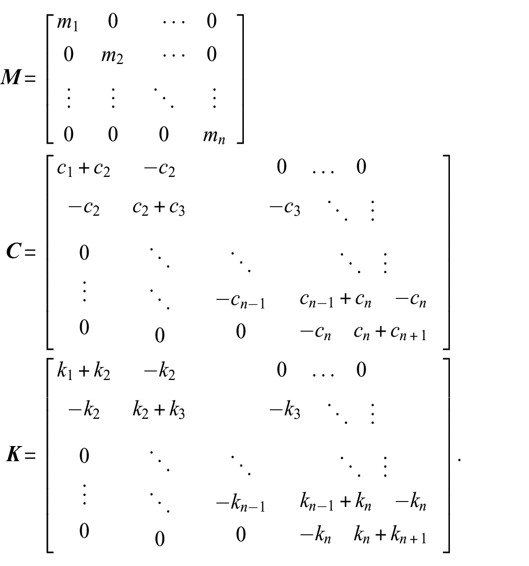
where

where
and
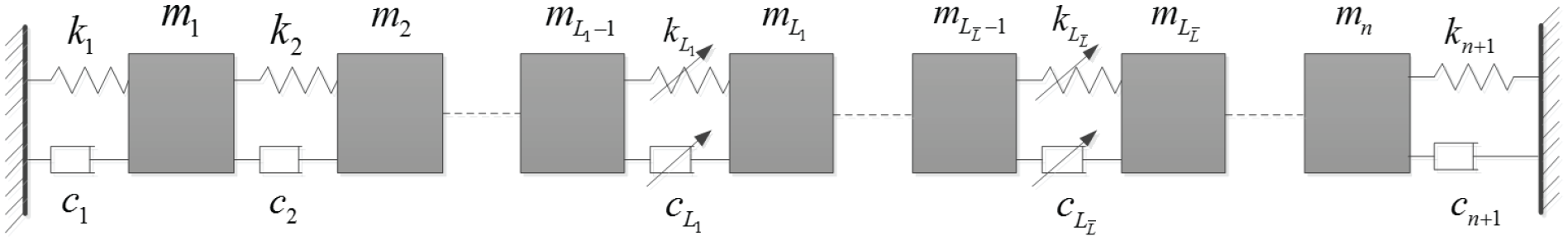
MDOF nonlinear system.
Output frequency range of Nonlinear MDOF structural systems
In linear systems, the output frequency range corresponds to the input frequency range. However, this is not the case in nonlinear systems. For instance, if the frequency range of input u(t) of the system Equation (14) is
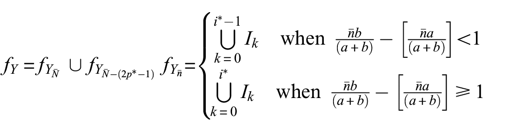
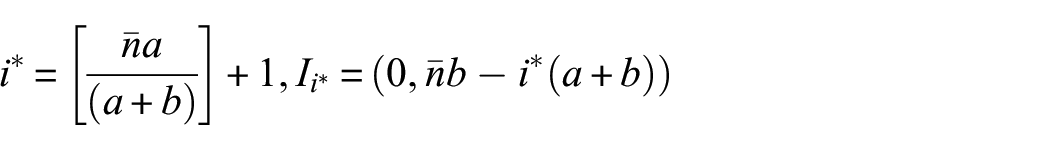
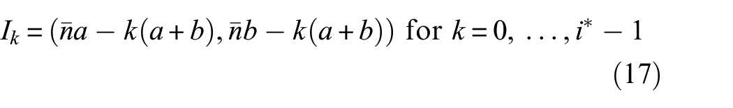
where
Transmissibility function and associated properties of nonlinear MDOF structural systems under general inputs
The transmissibility function of nonlinear output frequency response functions between two consecutive masses i and i+1 at the frequency
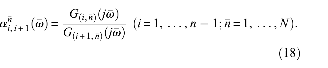
Equation (18) for system Equation (14) provides the basis for a series of fundamental propositions concerning the transmissibility of the NOFRF in response to general inputs. These propositions can be summarized as follows:
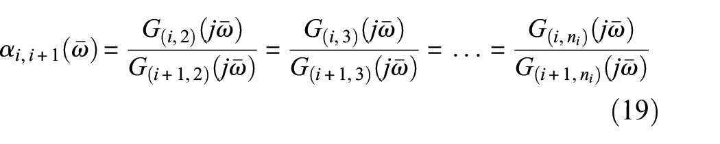
where
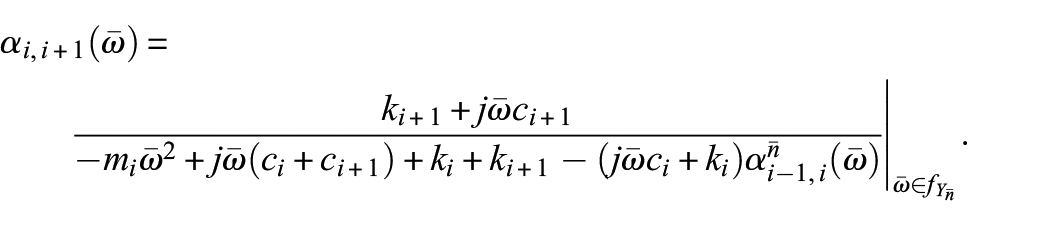
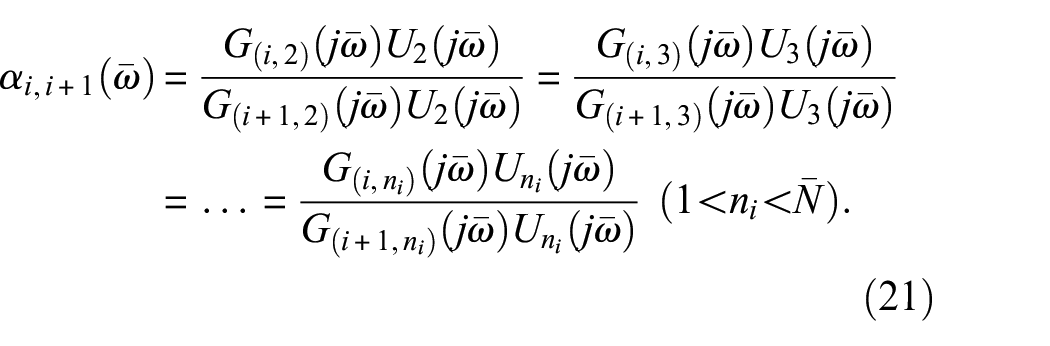
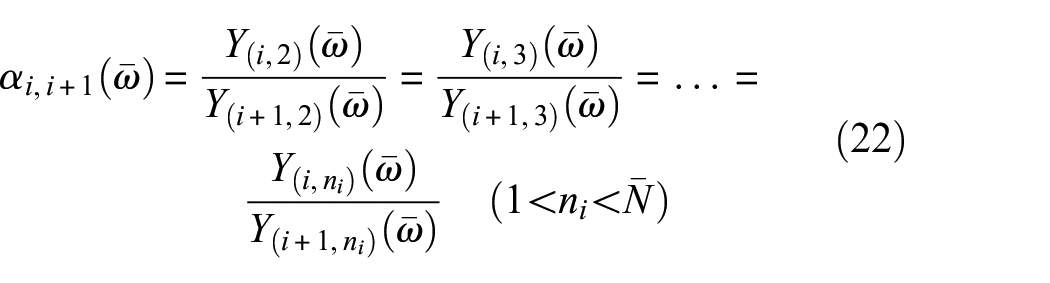
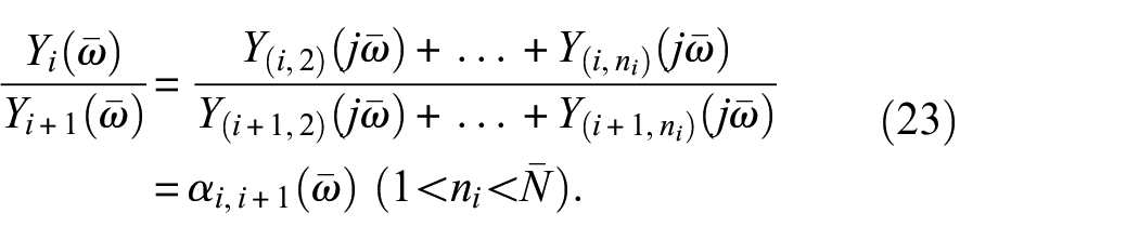
This proposition implies that the transmissibility function of the NOFRF between two consecutive masses i and i+1 remains constant for the frequency
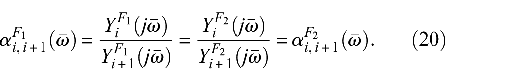
Equation (20) uses the superscripts
Therefore,
and
The validity of Proposition 2 is ascertained by the fact that
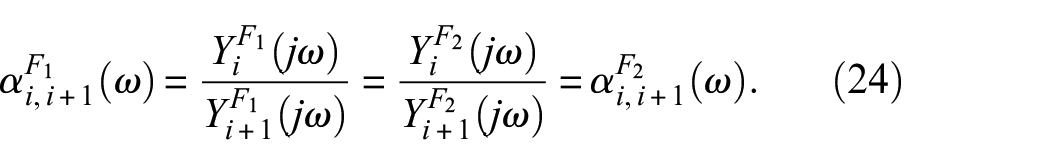
The proposition asserts that the output-based transmissibility function remains invariant in the presence of two loading scenarios characterized by identical input frequency bands
Damage detection and localization methodology
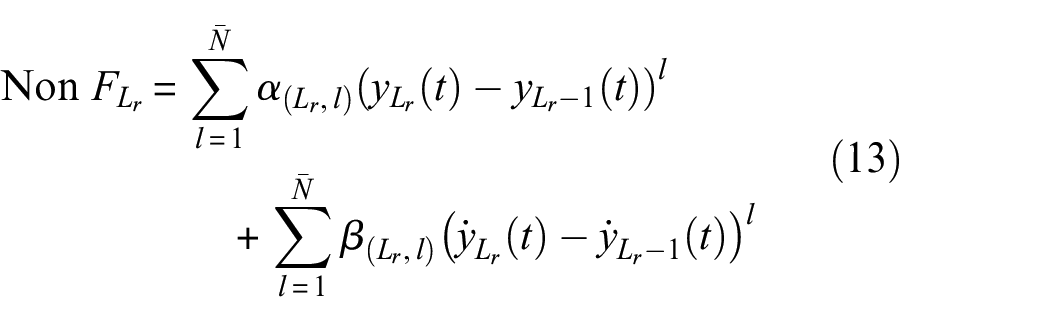
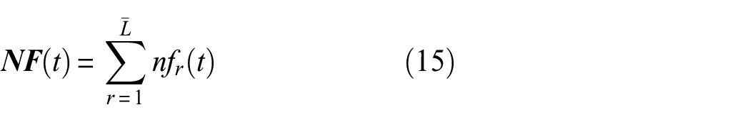
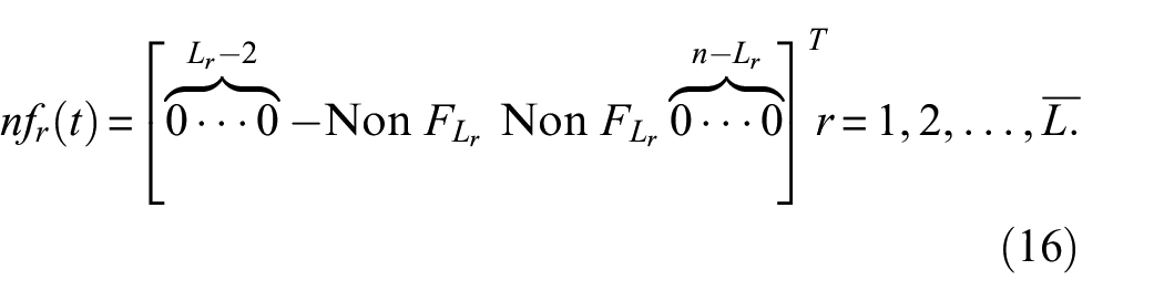
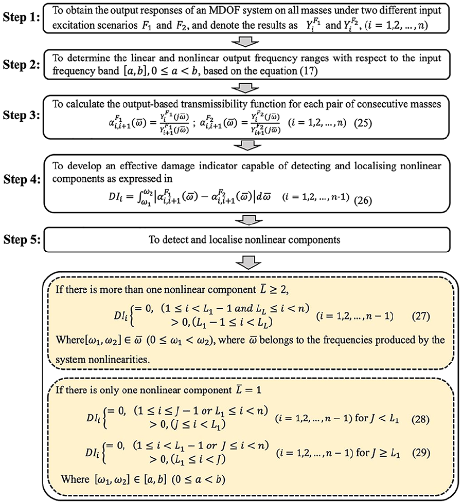
Based on Proposition 2, a new damage indicator, as presented in Equation (26), can be proposed to detect the existence and localize nonlinear components in MDOF systems. This methodology involves a five-step procedure that can be summarized as the following diagram.
Simulation study
In order to validate the effectiveness of the proposed methodology, a 10 DOFs Mass-spring-damper system has been simulated and coded in commercial software Matlab® shown in Figure 2. Damping is assumed to be proportional damping, for example,
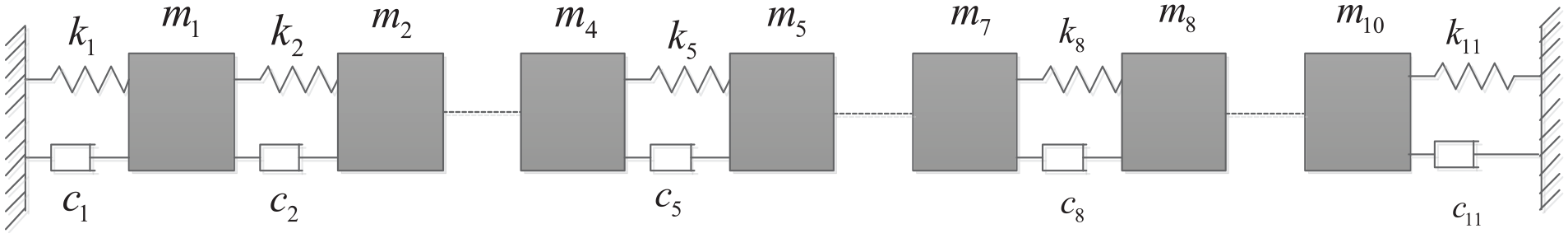
Ten DOFs mass-spring-damper system.
The detailed parameters are assigned as follows:


Equation (13) takes into account a level of nonlinearity of up to three,
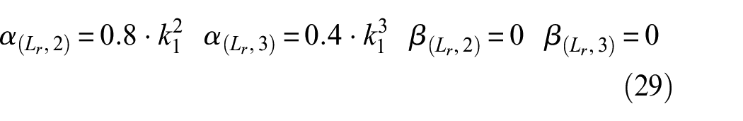
where
The general input 17 is given here:
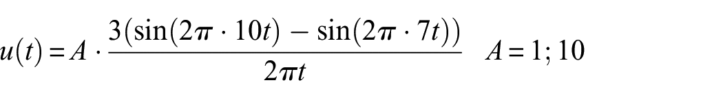

Equation (30) serves to generate an input signal with a bandwidth of [7, 10] Hz at a sampling frequency of 100 Hz.
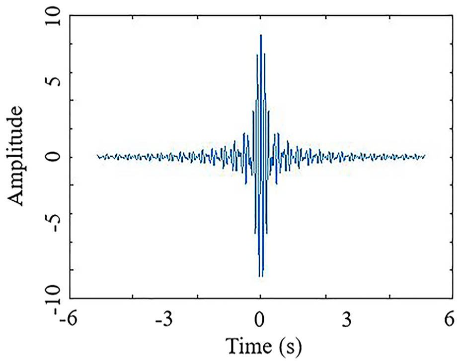
Time history of the general input.
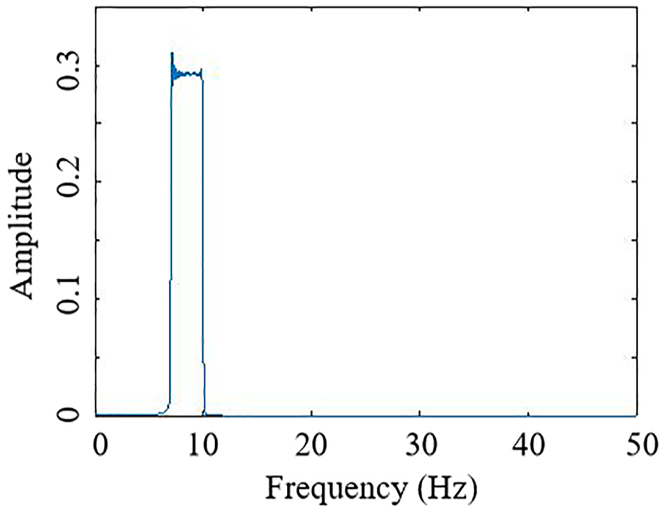
The spectrum of the general input.
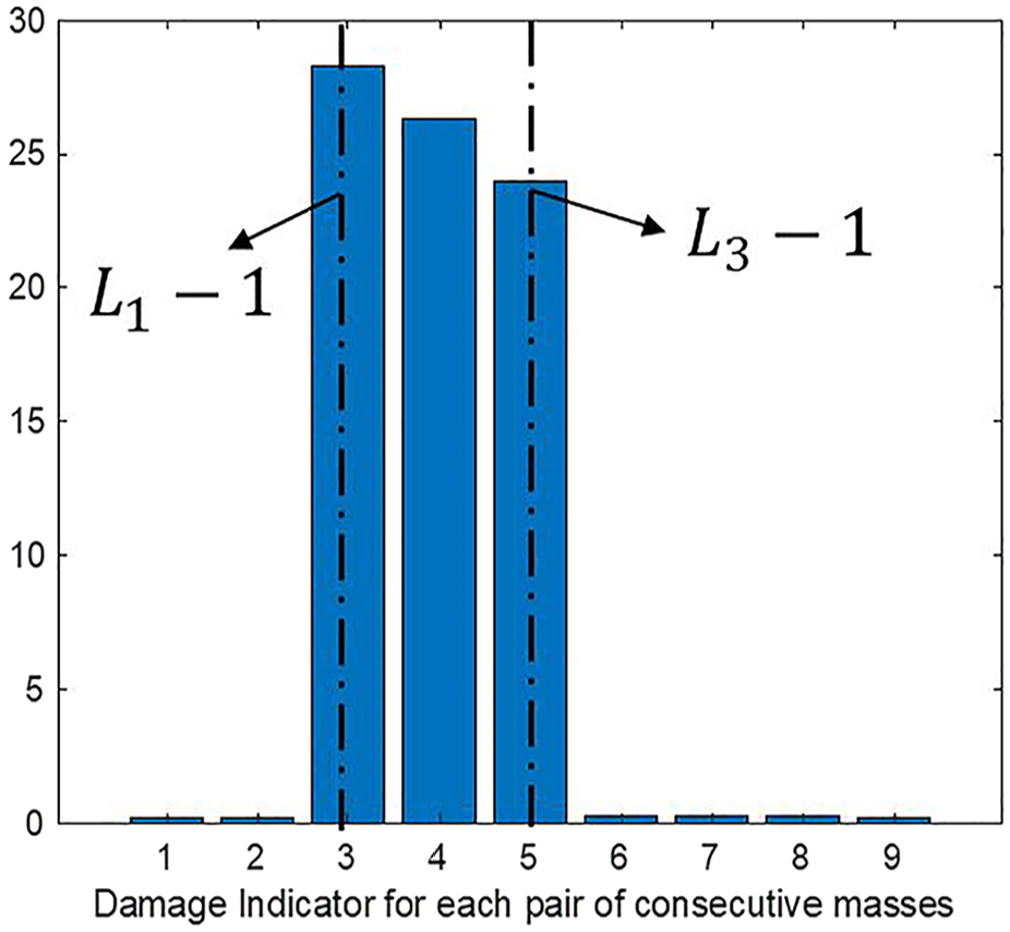
Identification of single nonlinear component for MDOF system
Input
Assuming that the system is linear and that the input is applied to the 3rd mass with an amplitude of
Given that the system under consideration is linear, the output frequency range matches that of the input, spanning from 7 to 10 Hz, as illustrated in Figure 5. However, incorporating two nonlinear springs into the system results in a remarkable change in the output spectrum, as shown in Figure 6. The nonlinearity causes a partial transfer of output energy from the original frequency range of [7, 10] Hz to both lower-frequency regions ranging from [0, 6] Hz and higher-frequency regions (11, 50] Hz. This redistribution of energy across the frequency spectrum is a significant demonstration of the impact of nonlinearities on the behavior of a system. Equation (25) is employed to calculate the transmissibility function for each of the two successive masses at linear frequency range
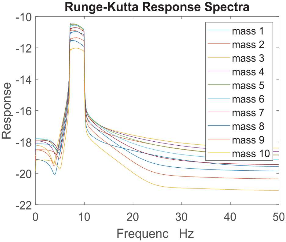
Output spectra of the 10-DOF linear system (in logarithms).
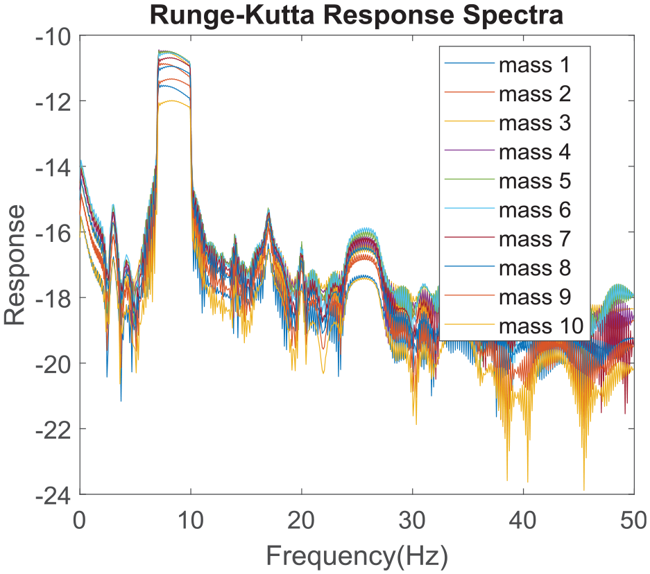
Output spectra of the 10-DOF nonlinear system (in logarithms).
From Equation (28), any damage indicator
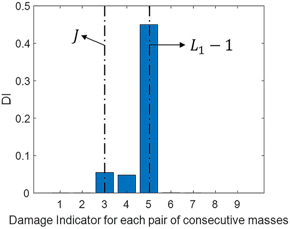
Damage indicator based on [8, 10] Hz.
Identification of multiple nonlinear components for MDOF system
The 3rd and the 7th masses are subjected to input forces
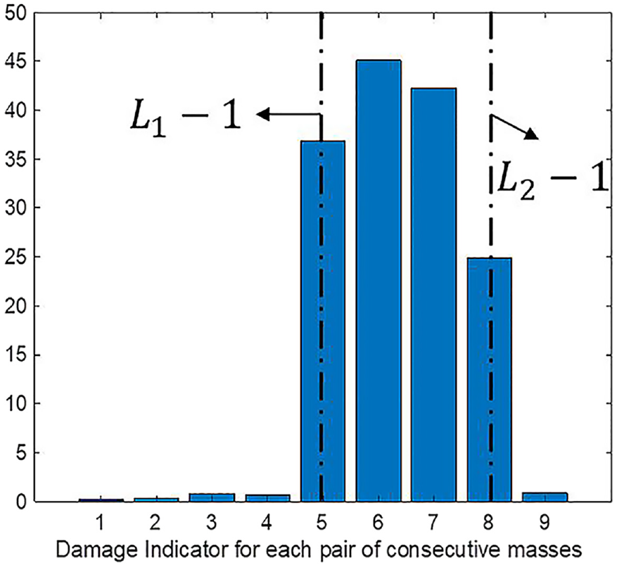
Damage indicator based on [24, 26] Hz.
According to Equation (27), any damage indicator
In this case,
The only region with nonzero damage indicators, as depicted in Figure 9, spans from
Damage indicator based on [24, 26] Hz
The output-based transmissibility function at frequency
Identification of a single crack on a beam structure in FEM
Consider a Euler–Bernoulli beam element shown in Figure 10. The displacement along the
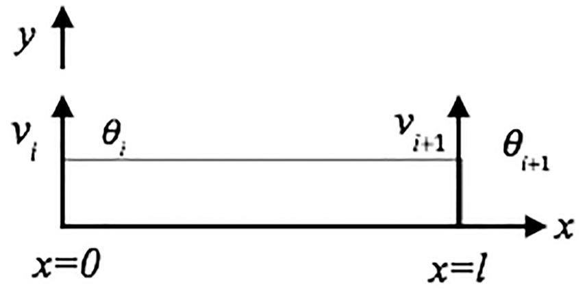
Two nodes beam element.
There are four DOFs in the beam element, define them as
The element mass matrix
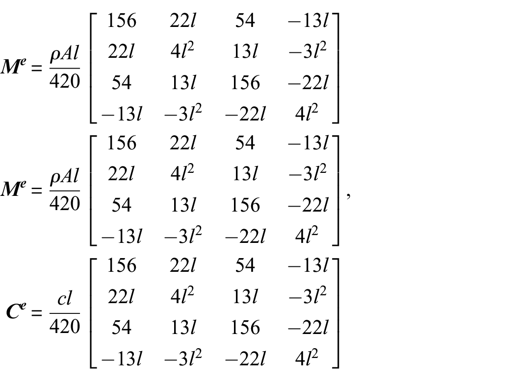
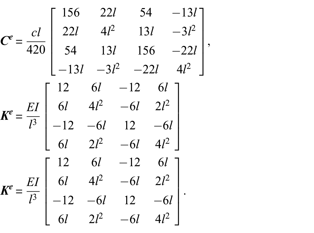
where
If a beam contains a crack, there will be a nonlinear phenomenon in its vibration. A simplified model of open crack was proposed by Sinha et al., 25 which can introduce the damage for the beam elements.
The flexural rigidity close to the crack,
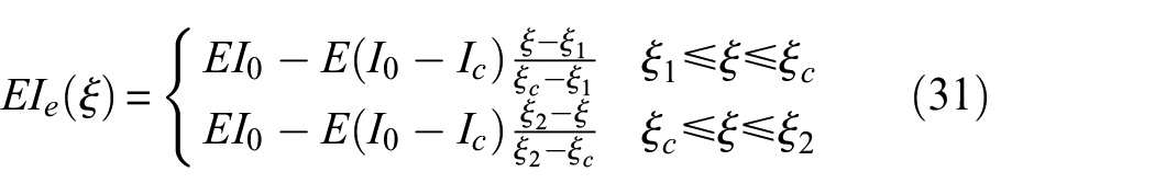
where

where
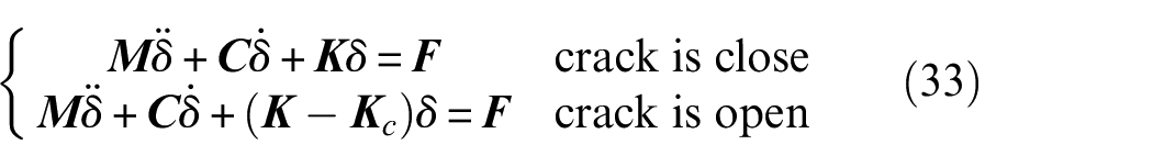
The governing equation in finite element form can be written as:
A 10-element (11 nodes) Euler–Bernoulli cantilever beam is employed and simulated in the commercial software MATLAB, shown in Figure 11. The dimensions of the beam are set as 1.00 × 0.015 × 0.015 m3 (Length × Width × Depth). It has a mass density of 7680 kg/m3, an elastic modulus of 208 GPa, and a damping ratio of 0.001. The beam is subjected to a breathing crack of half the beam’s depth, precisely located at the midpoint of the 6th element. The broadband input, given by Equation (34), is considered under two scenarios. Figure 11(a) illustrates a single load acting on DOF
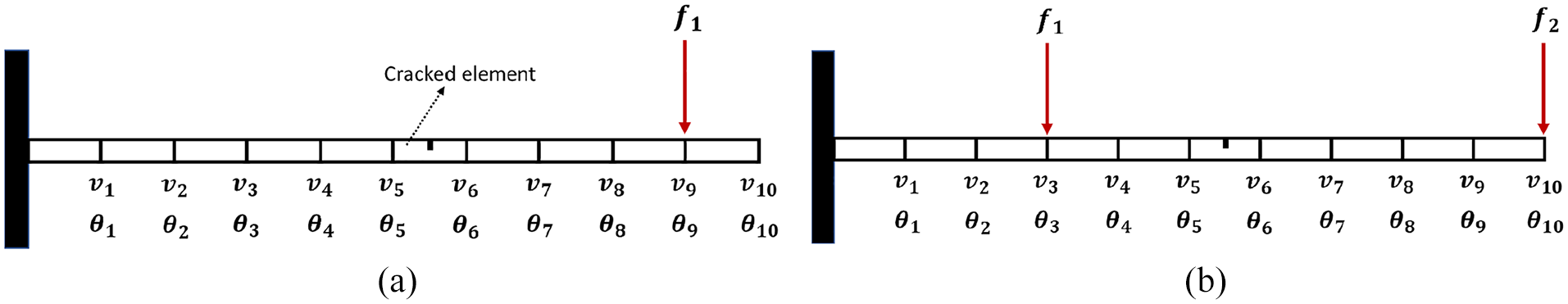
The FEM model of a cantilever beam. (a) Single load at node 10. (b) Two loads at node 4 and node 11.

Utilizing the fourth-order Runge–Kutta method, the dynamic response of the cracked beam model is obtained. To assess the existence of the crack, the transmissibility outside the driving frequency range, [12, 14] Hz, is analyzed. Figure 12 demonstrates the identification outcomes. The position of the crack, located between the DOFs
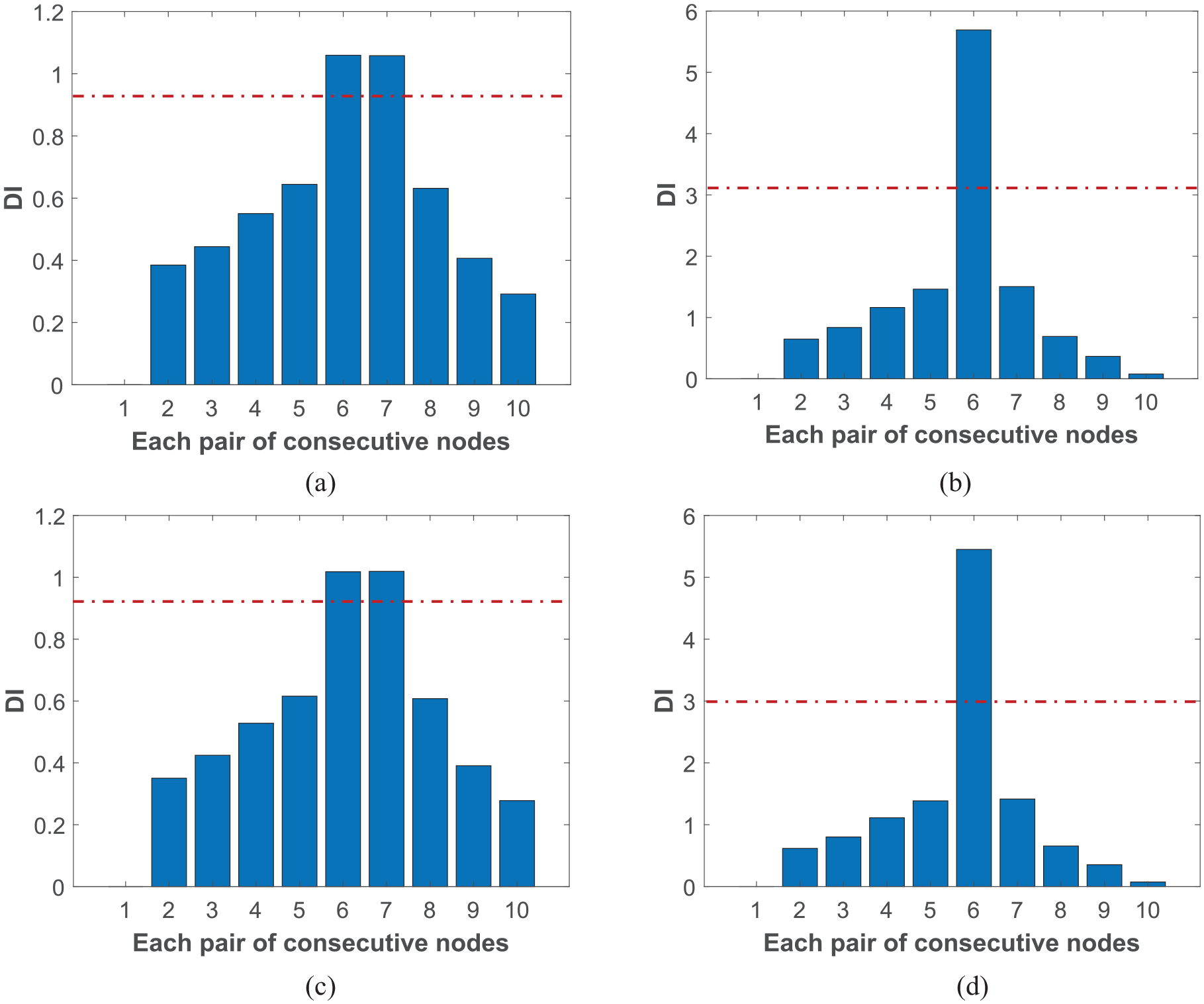
Damage indicator of the FEM model. (a) Damage indicator of [12, 14] Hz based on bending displacement under a single load. (b) Damage indicator of [12, 14] Hz based on rotation displacement under a single load. (c) Damage indicator of [12, 14] Hz based on bending displacement under two loads. (d) Damage indicator of [12, 14] Hz based on rotation displacement under two loads.
The effectiveness of the proposed methodology in identifying a single nonlinear component in a beam FEM model is evident. This can be attributed to the beam element’s higher number of degrees of freedom compared to MDOF systems, which enables the propagation of nonlinearity from the crack to other elements. This observation confirms our conclusion that the number and placement of loading inputs have no effect on NOFRF transmissibility (
Experimental study
The focus of this section is to localize the breathing crack behaving nonlinearly in a steel-beam structure by the proposed damage indicator based on the NOFRF transmissibility function through the use of an innovative distributed fiber optical sensing-based technique. In contrast to the conventional transducers that suffer from single point sensing, making it challenging to cover most vibration data and impossible to precisely localize the damages such as cracks. Instead, distributed fiber optics, together with LUNA ODiSI-B Optical interrogator, 26 is adopted to acquire vibrations in terms of dynamic strain, which aids in offering a dense measurement solution, readers are referred to References27–29 for more details.
The ODiSI-B Series integrator is designed by American company Luna Innovations, based on the Rayleigh scattering, and specifically engineered to embrace the testing challenges of advanced materials and systems. It offers high-speed, fully distributed strain and temperature measurements with high spatial resolution, with hundreds of sensing locations per meter on a single fiber, all of which are interrogated at frequencies up to 250 Hz.
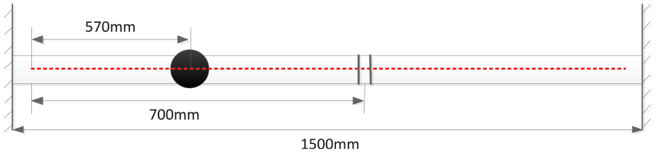
The most effective methodology for generating breathing cracks is through fatigue-inducing experiments. However, in this case study, a more efficient and time-saving method for generating “breathing crack” has been employed. A rectangular block notch measuring 40 × 3 × 2 mm (length × width × thickness) was removed, and a steel block of the same dimensions was filled in with adhesive, as illustrated in Figure 13.
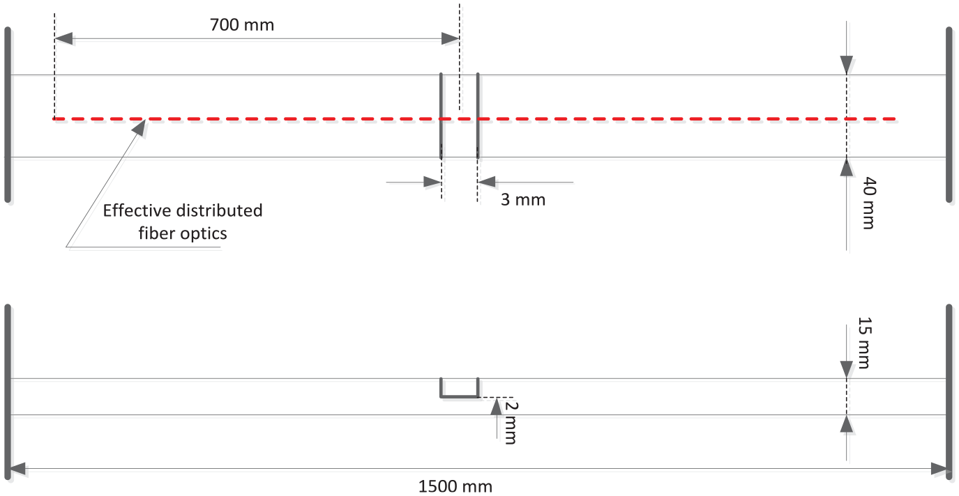
Configuration of beam structure with crack and distributed fiber optics.
The investigation is performed on a clamped-clamped steel beam with a dimension of 1.5 × 0.04 × 0.015 m. The installation configuration of distributed fiber optics is denoted by the red dashed line in the diagram above. A distributed fiber-optic sensor with an effective sensing area of 1.28 m is attached to the surface of the beam. The crack is located 700 mm to the left of the initial effective section, as illustrated in Figure 13. With a sampling frequency of 250 Hz and a sensing spacing of 2.6125 mm, the effective sensing region encompasses 497 sensors. The crack, as shown in Figure 14, is approximately at the 267th sensor.
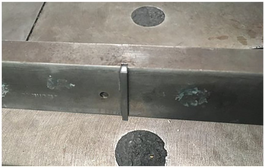
Crack in the beam.
Figures 15 and 16 demonstrate the configuration of the corresponding experimental system. A broadband chip input signal is generated by NI-MyDAQ, which is transmitted to the power amplifier and reaches the mini-Shake to generate vibrations into the beam. The generated dynamic responses of the beam are then collected via the attached distributed fiber optics, demodulated by LUNA OSiDI-B integrator, and saved in PC2. A zoom-in view of glued fiber-optics is presented in Figure 17.
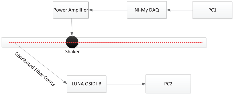
System configuration.
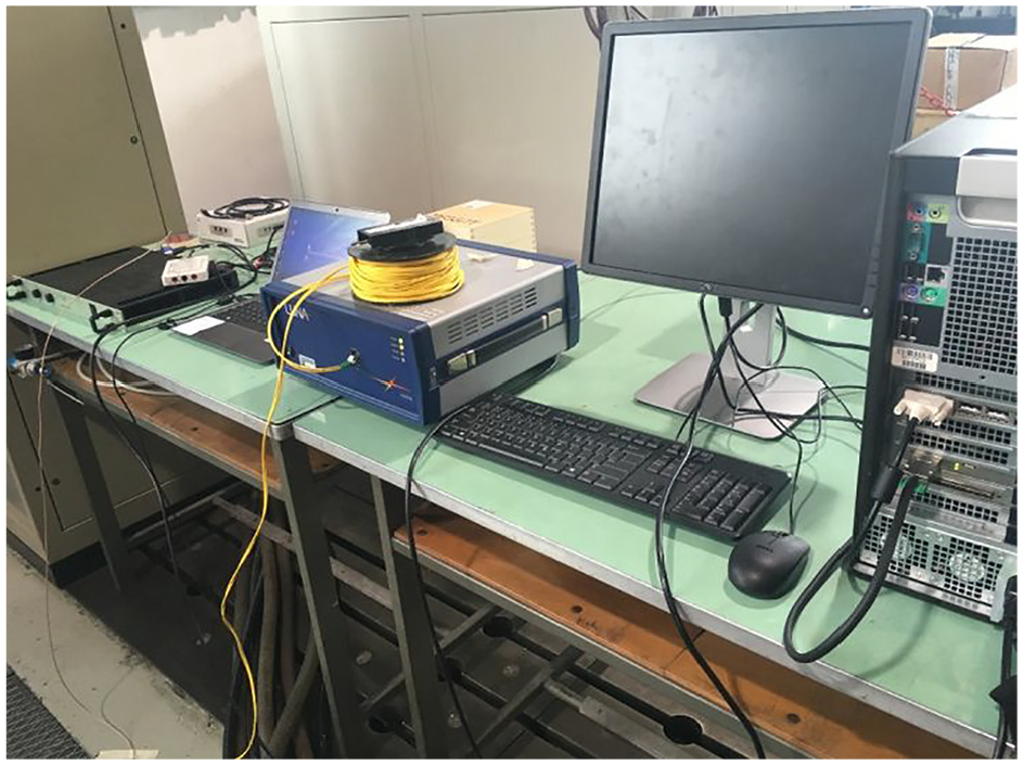
Configuration of the experimental system.
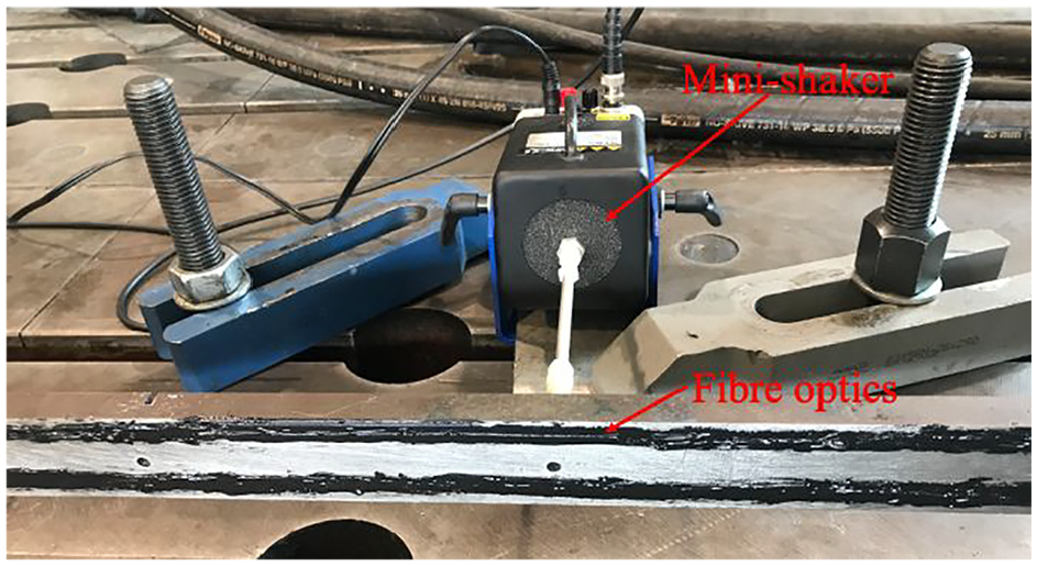
Zoom-in view of fiber optics.
To illustrate the feasibility and effectiveness of the proposed methodology, the operational scenario (the input on the left side of the beam, and its configuration is shown in Figure 18) has been considered in the experimental verification test.
Configuration of scenario 1.
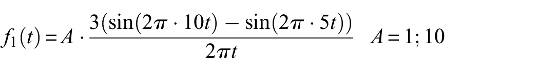
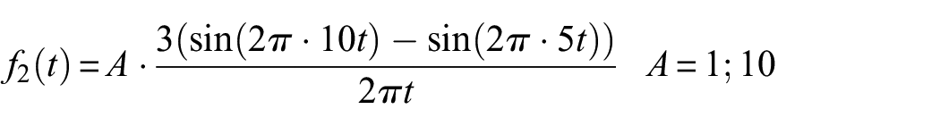
Chirp signals with a bandwidth of [25, 45] Hz with two different excitation levels A and B (B/A = 5) are considered inputs, as displayed in Figure 19 and 20 in the time domain and frequency domain, respectively, with unit amplitude.
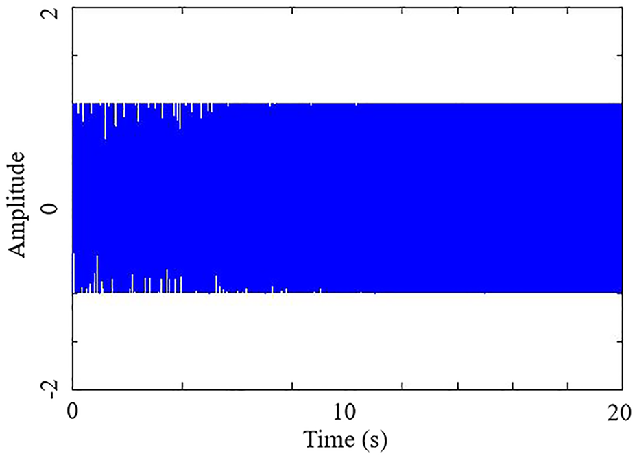
A chirp input signal in time domain.
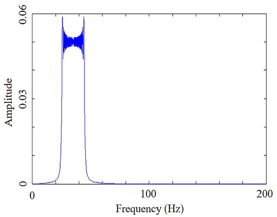
A chirp input signal in frequency domain.
The input signal is generated by the minishaker positioned 570 mm to the left of the fiber optics, which corresponds to the 219th sensor. The crack is located 700 mm to the left of the fiber optics, corresponding to the 267th sensor. Under excitation level A, the strain responses of all 497 sensors, including the distributed fiber optics, in the time domain are presented in Figure 21 for the 20-s duration of the chirp input.
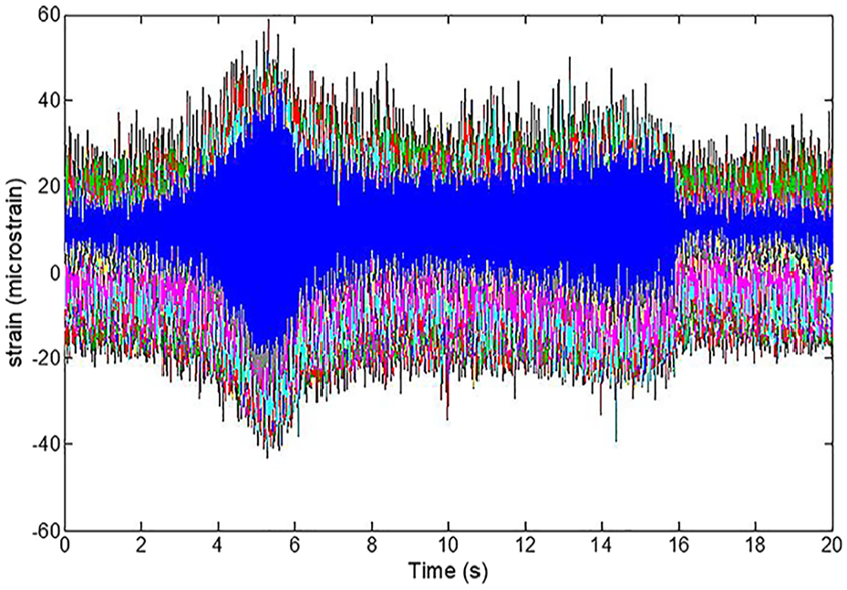
Strain responses of 497 sensors in time domain.
To minimize the effects of noise, the test is repeated five times. Subsequently, the output-based transmissibility function is computed based on the spatially dense dynamic responses of the cracked beam. The frequency range of interest for the damage indicator is selected as [120, 140] Hz, with higher values indicating a greater likelihood of structural damage. Damage indicators are computed and presented in Figure 22, which identifies the high-risk region within the beam element range of 240–270 due to the presence of nonlinearities by setting a simple threshold. This finding is in agreement with the observed damage scenario, where the crack is located near the 267th beam element within the aforementioned high-risk area. Moreover, it is noteworthy that the employment of the dense measurement technique allows for enhanced localization of the crack.
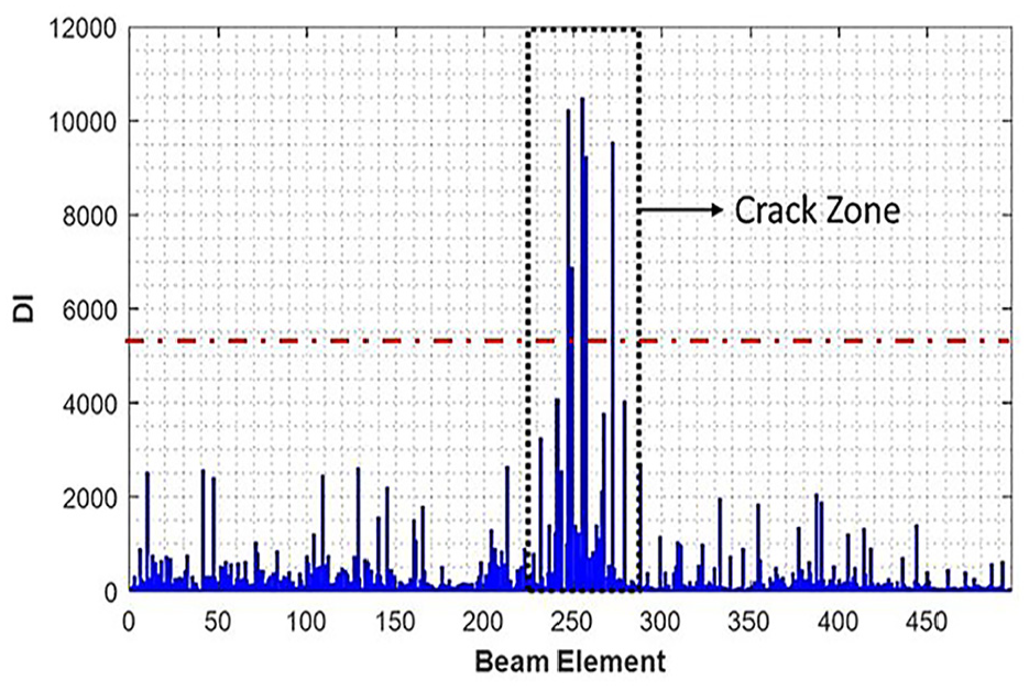
Damage indicator.
Conclusion
This article presents a novel methodology for detecting and localizing damage with nonlinear features in MDOF systems subject to general inputs. The methodology leverages the intrinsic characteristics of the transmissibility of nonlinear systems defined based on the NOFRF concept, and exploits the transmissibility between adjacent masses over the frequencies generated by the system nonlinearities. An output-based transmissibility function is then formulated and utilized to identify single and/or multiple nonlinearly damaged components in the system. The proposed methodology has been validated through relevant simulation studies, demonstrating its feasibility and effectiveness. The premilitary experimental investigation on a steel beam structure with a breathing crack using distributed fiber-optic sensors has generated a damage indicator with acceptable fluctuations, demonstrating the potential of the proposed methodology in the identification of damage on practical engineering structures.
Yet, the proposed methodology has certain limitations: (1) The propositions are based on chain-like MDOF systems that do not account for coupling effects between DOFs and the complexity of degrees of freedom in a real continuous system. In reality, DOFs are often internally linked, which can lead to the propagation of nonlinearity from one specific location to surrounding elements. Therefore, Proposition 3 is not very applicable to complex engineering structures when considering only a single nonlinear component. Although the presented FEM and experimental studies verify the feasibility of detecting single nonlinearity based on Proposition 2 rather than Proposition 3, a detailed and rigorous theoretical study will be continued; (2) This experimental case study demonstrates the process of identifying a single nonlinear component, such as a breathing crack, using distributed fiber optics. This supports our proposed methodology based on the concept of the NOFRF-based transmissibility function under general inputs. However, determining a suitable and reliable threshold, such as statistical thresholding based on noise level, for identifying high-risk regions requires further research and discussion. (3) The proposed methodology is currently only able to localize the entire region covered by nonlinear components. Precisely locating the individual nonlinear components remains challenging.
This study has preliminarily established a framework for nonlinear damage identification and localization of MDOF systems based on NOFRFs under general inputs. Further investigation will focus on addressing the summarized limitations to develop a robust and more generalized solution applicable to complex engineering structures.
Footnotes
Appendix 1
The first row of governing equations of the system Equation (14) can be written as
According to the Volterra series theory of nonlinear systems and the definition of the NOFRFs, the ith output nonlinear SIMO system Equation (14) can be represented as
where
Substituting Equations (A1.2) into (A1.1) yields
which implies that
where
Considering the general nature of
Substitute NOFRF transmissibility Equation (18) into Equation (A1.5). Therefore,
Note that here
Similarly, the NOFRF transmissibility for the
From the general expression for the NOFRF transmissibility Equation (A1.7) where the masses don’t connect with nonlinear components and are not subject to the input, it can be known that NOFRF transmissibility only depends on its linear physical parameters, independent of nonlinearities and input.
The NOFRF transmissibility between mass
where
Using
The following relationship holds for the NOFRF transmissibility where the mass is subjected to the input,
One interesting thing needs to be mentioned that the establishment of
It can be known that Equation (A1.10) conforms to the general expression (A1.7) of NOFRF transmissibility.
Since the calculation of the NOFRF transmissibility is a forward iterative process, each NOFRF transmissibility includes the effect of the previous NOFRF transmissibility, thus the NOFRF transmissibility
Starting from the last row of the moving equation system (14) between mass
Appendix 2
All terms associated with
where
Note:
Then the output spectra can be rewritten as
Therefore, the output spectrum at nonlinear frequency components of mass i can be obtained
Then the output-based transmissibility function for each pair of consecutive masses can be derived as
If there is more than one nonlinear component, that is,
Equation (A2.5) states that the output-based transmissibility function at nonlinear frequencies for each consecutive pair of masses is insensitive to the presence of a nonliar component and solely relies on the physical properties of the system. However, the existence of multiple nonlinear components results in a dependence of the output-based transmissibility function at nonlinear frequencies not only on the physical parameters of the system but also on the nonlinear restoring force, as shown in Equation (A2.6). Consequently, the presence of a solitary nonlinear component does not impact the output-based transmissibility function at nonlinear frequencies.
Appendix 3
Considering when
The NOFRF transmissibility where the masses don’t connect with nonlinear components and are not subject to the input only depends on its linear physical parameters, independent of nonlinearities and input. Therefore, the output-based transmissibility function remains unchanged under two different loading inputs at the same mass J for the masses i
Equation (A3.2) still holds valid via a forward iterative process in the governing equations of the system (14) until
where
From an alternative viewpoint of the backward iterative process in the governing Equation (14), the NOFRF transmissibility for the
As seen from Equation (A3.5), the same conclusion as Equation (A3.3) can be drawn for the output-based transmissibility function between mass
The relationship Equation (A3.6) holds true until
where
Using
Therefore, outside the DOFs connected to one single nonlinear component (
The derivation for the scenario of
Declaration of conflicting interests
The author(s) declared no potential conflicts of interest with respect to the research, authorship, and/or publication of this article.
Funding
The author(s) received no financial support for the research, authorship, and/or publication of this article.