
Abstract
A robust and reliable condition monitoring and fault diagnosis system is crucial for an efficient operation of industries. Because of the advances in technologies over the past few decades, there is an increased interest in developing intelligent systems to perform tasks that traditionally rely on knowledge, experience and expertise of an individual. It is known that unexpected breakdowns have wide implications in production processes. Thus, it is vital to be able to know the machine condition and detect at the earliest possible stage the defects when they occur. Aiming at an industrial application, in this study, a two-step approach is proposed for the fault detection and diagnosis of rotor-related faults. The implemented algorithm is a pattern recognition supervised artificial neural network, which through information extracted from vibration signals allows one to identify the health status of the machine. In the first step, the model identifies whether the machine is healthy or faulty. This is important information for any industry to operate the machines. Once the machine condition (healthy or faulty) is known and if it is faulty, then only faulty machine parameters are used in the second step to know the specific fault. The model is initially based on existing experimental data, and then, it is further validated with mathematically generated data. The proposed two-step approach model and the trained framework are applied blindly at a different machine speed, where the dynamics of machine is expected to be different. The excellent results obtained suggest this approach as a possibility for industrial application.
Keywords
Introduction
Current advances in technology regarding both techniques and equipment have opened the possibility of implementing artificial intelligence to different engineering fields. Along with these developments, the demand of a higher performance in industries is imminent. Industrial maintenance is one of the areas that have gained major attention, since it widely affects all processes, including production and product quality, availability, reliability, safety and costs.
The review conducted by Lei et al. 1 shows that there has been a sharp increase in the number of publications related to the application of machine learning (ML) to machine fault diagnosis since 2010. These intelligent methods provide the possibility to correlate the data collected from the machine to its health status, releasing the high dependency of traditional condition monitoring techniques on the knowledge, experience and expertise of the individual that performs such tasks.
Rotating machines are recognized as a vital element in many industries, 2 with the detection of their faulty states at an early state being a matter of high interest. In literature, a wide range of ML approaches that have been applied to different mechanical components in order to assess their health condition are found. 3 Among the most commonly implemented approaches are support vector machine (SVM) and artificial neural networks (ANNs).
An experimental study on gearbox defects has been conducted by Mohamad et al. 4 . They compared the accuracy on the diagnoses of the linear SVM against the Gaussian SVM, showing an overall performance of 97.1% and 97.8%, respectively, on the separation of faulty from healthy samples at a constant unique operational speed. Despite these results, their model classified some of the faulty samples as healthy in both approaches. Zing et al. 5 achieved higher performance on the implementation of the SVM to gearboxes with an accuracy of 99.53%.
The SVM method has also been successfully applied in the study of centrifugal pump defects, such as flow blockage and cavitation.6–8
Zhang et al. 9 studied bearing defects on changing working conditions through the ANN. They proposed a transfer learning approach, which was implemented on two scenarios of changing conditions, showing in both cases an improvement when compared to the ANN without transfer learning. However, the overall performance in both cases remains under 92%.
In a comparison made in fault detection in bearings between the SVM and the ANN 10 , it is found that better performance shown by the SVM is for the identification of inner race defects, while the ANN delivers higher accuracy on the detection of roller element defects.
Overall, most of the available research considers a small number of defect types, a unique operational condition, or unique source of data. This makes it difficult to extend the findings to possible adaptability to different operational conditions without affecting reliable performance. While the study cases are based mainly on laboratory-generated data, mathematical approaches have also been adopted in order to simulate the defects. 11 Mathematical simulation, such as finite-element (FE) method, arises as a powerful tool, as it allows data simulation, which is one of the main constraints of ML models based on pattern recognition.
Under the aim of delivering an approach feasible for industrial application, in this research, a two-step rotor fault diagnosis model is proposed. Within the industries, a number of identical machines may run simultaneously but with different dynamics behaviours. Hence, the assessment of health of each machine based on vibration-based condition monitoring is generally difficult through the manual analysis of the measured vibration data, and such diagnosis also depends on the engineering judgements and experience. Therefore, it is important to have a smart model that can identify the machine condition first, which is important to the operations, and the model can be used blindly to other identical machines, which may have same or different dynamics behaviours. Hence, a two-step approach is proposed using the measured vibration data and the ANN-based smart model for diagnosis. In the first step, the model identifies whether the machine is healthy or faulty. This is important information for any industry to operate the machines. Once the machine condition (healthy or faulty) is known and if it is faulty, then only faulty machine parameters are used in the second step to know the specific fault. The model is initially developed based on the measured vibration data from an experimental rotating rig, and then, it is further validated with mathematically generated data using the FE model of the rig. Vibration parameters that are used in the ANN model are normalized by the rotor unbalance response in order to unify the data and remove the impact of the unbalance so that the proposed model can be used even when the machine runs at different speeds. This is further validated through applying the trained two-step model blindly at a different machine speed where the dynamics of the machine is expected to be different.
This paper provides the details of the proposed method, the ANN model, and the normalized vibration-based parameters used for machine health condition diagnosis. The observations and results of the proposed model are discussed through both experiments and FE analysis.
Proposed model
In this study, the implementation of a classic ML model, namely, pattern recognition ANN, for fault diagnosis in rotating machines is proposed. The approach is based on the available measured vibration signals from an experimental rig in laboratory conditions. 12 Several parameters have been selected and optimized in order to accurately characterize the dynamics of the machine. These parameters are arranged into inputs to feed the developed ANN, obtaining the condition of the machine as output. The initial model performance has been improved over time by the adjustment and optimization of the features extracted from the measured data. At this stage of the study, further improvement is proposed by the application of this algorithm in a two-step approach.
Parameters
The process of optimizing the vibration-based parameters to identify the rotor-related faults is summarized here. The parameters initially used in the development of the ANN were extracted only from the time domain. 13 They correspond to statistical features commonly used in engineering applications and also in vibration-based condition monitoring. The main idea behind this approach was to implement a simple metric, which did not rely on the individual expertise level on signal processing. By this approach, the ANN model has provided excellent results, showing its adaptability to different operational speeds. 13 However, there was a lack of accuracy on the specific fault identification when it was blindly tested in a different operational condition of the machine. FE simulations have also shown similar observations. 14 Hence, time-domain vibration parameters may not be good enough for industrial applications.
Further study was conducted to overcome the limitation observed in only using the time-domain parameters. Instead of changing the ANN model, both time- and frequency-domain parameters were included as the input vectors.15,16 The selected time- and frequency-domain parameters are based on the rotor dynamics and are widely used in the industries for fault detection. 17 Hence, the use of both time- and frequency-domain parameters based on the established theoretical concepts in the rotor dynamics has improved the model’s performance nearly close to 100%. 15 These results were further validated by mathematical data generated on an FE model of the experimental rig. 18
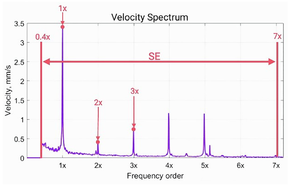
In this study, further improvement is explored on the model performance by normalizing the vibration-based parameters by the unbalance response in order to unify the data and remove the impact of the unbalance. The values extracted from the frequency domain are normalized by the amplitude in the velocity spectrum at the frequency of 1×– one times the operational speed. Normalization is introduced with the aim of reducing the impact of processing data collected at different operational speeds.
The optimized time- and frequency-domain parameters in the earlier study
15
are used again, which are listed in Table 1. From the time domain,
Normalized vibration-based parameters used as the input vectors.
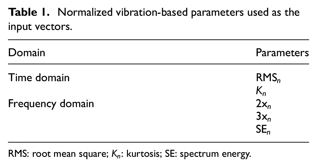
RMS: root mean square;
Values extracted from the frequency domain.
These values are calculated from the vibration signals collected at the measuring points of the machine and arranged into the input vectors. Thus, each input vector per bearing vibration measurement location contains five elements, as per Equation (1)
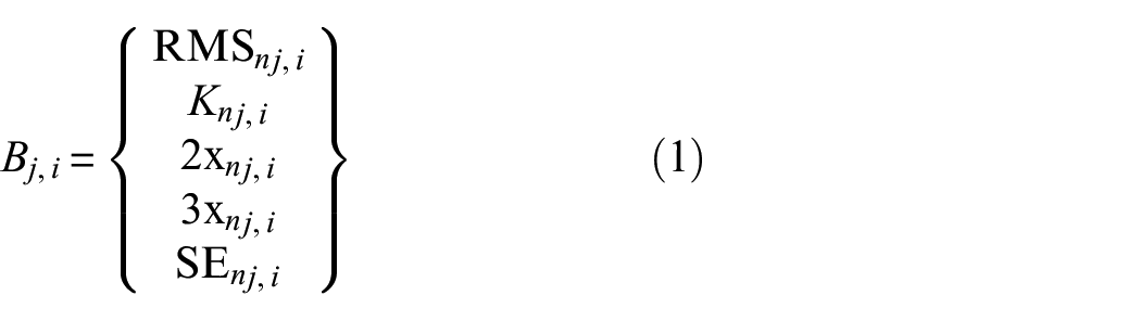
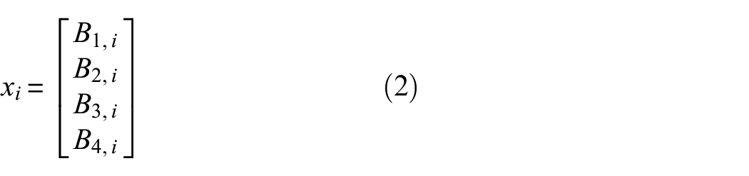
where B represents the bearing measurement location for the vibration, and subscripts j and i are jth bearing and ith vibration measurement (ith sample), respectively. The experimental rig used in this study has four measuring locations. Further details on the experimental rig and data are provided in section ‘Experimental rig and data’. Hence, the input vectors per vibration measurement for the rig are prepared as per Equation (2)
where

ML Model
The ML model implemented in this study is a classic pattern recognition ANN. This model is optimized in the earlier studies 15 , which is summarized here. The idea is to keep and standardize the same and simple ANN model and then only optimize the vibration parameters based on the rotor dynamics to make the diagnosis process easy and simple for industrial use. The ANN model consists of a multilayer perceptron, made by an input layer, four hidden layers and an output layer.
Hidden layers 1–4 are set with hyperbolic tangent sigmoid as transfer functions and are made by 1000, 100, 100 and 10 neurons, respectively. The output layer, which provides the final diagnosis or classification of the analysed samples, is set with softmax as a transfer function. For training the network, the set function is scaled conjugate gradient backpropagation, and the performance function is cross-entropy.
Data samples are randomly grouped; 70% of the total samples are allocated for training, while the remaining 30% is equally distributed for validation (15% of total samples) and testing (15% of total samples).
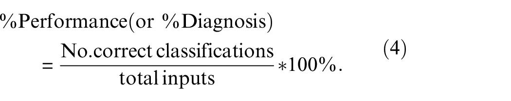
The overall performance or correct diagnosis rate is calculated as the correctly classified pieces of data over the total data processed in the supervised ML model. The calculation of performance is presented as follows:
Two-step implementation of the proposed fault diagnosis model
This study proposes to implement the supervised ANN presented in section ‘ML Model’ into a two-step approach. In the first step, the model is designed to identify the machine healthy or faulty condition, which is needed for the operation and management teams within any industries. Then, in the second stage, only faulty machine condition data (xm) are used to identify the exact fault within the machine so that the maintenance team can further plan for remedial actions. The two-step approach is represented in Figure 2.
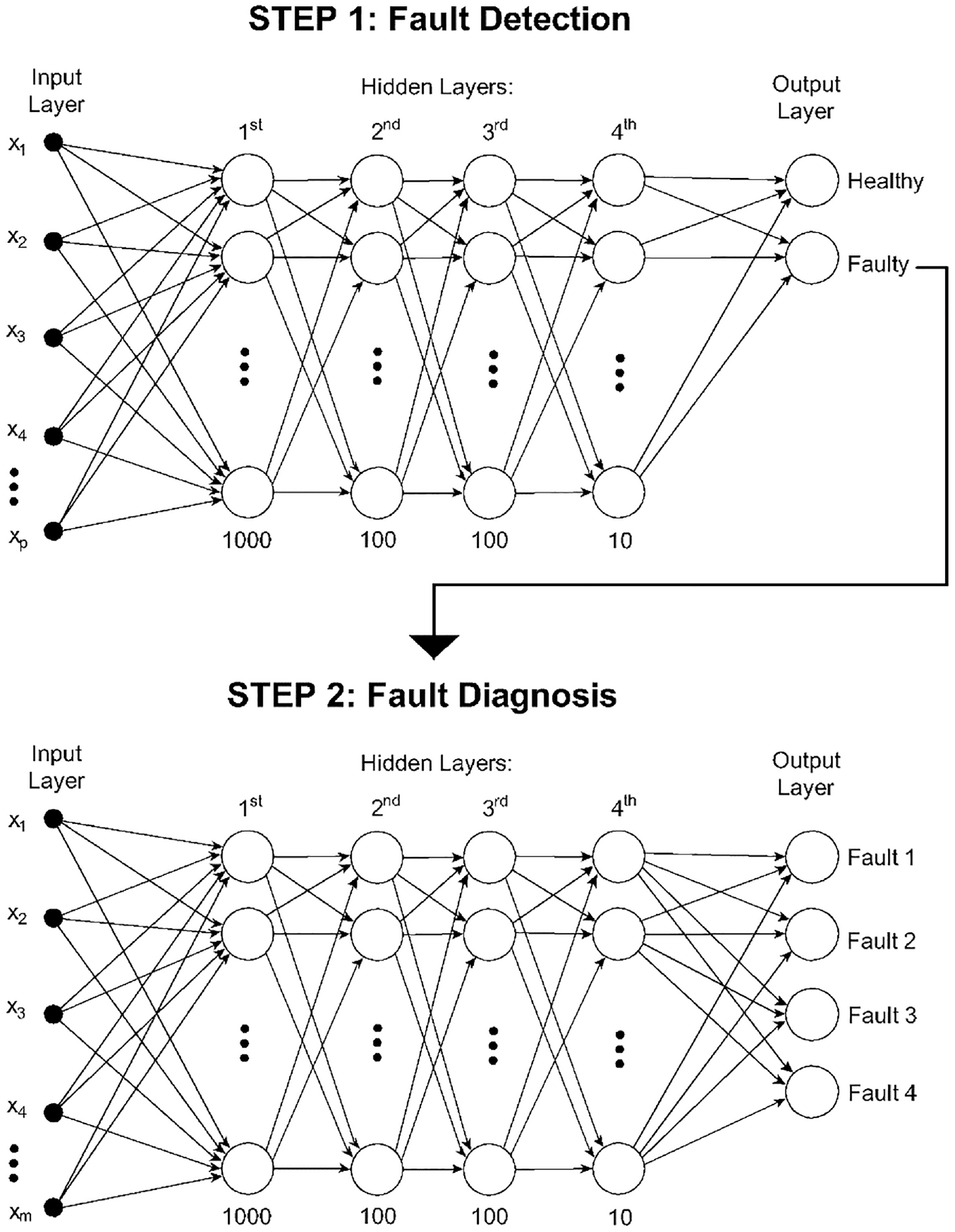
Schematic of the application of the smart fault diagnosis model developed in a two-step approach.
Within industries, a number of identical machines may be used simultaneously but with different dynamics behaviours. It is always difficult to develop a unique smart ANN model for each machine. Hence, it is also attempted to unify the trained model in Figure 2 at a machine condition and then blindly apply to the identical machines. Other machine conditions such as machine dynamic behaviour, operation conditions, etc. may be nearly same or different. This process is represented through the flowchart in Figure 3. In this study, the trained model in Figure 2 is blindly tested on the same experimental rig but operating at a different speed. The accuracy of 100% in diagnosis between the machine healthy and faulty conditions is important for the industrial purpose to run the machine and to maintain the plant safety.
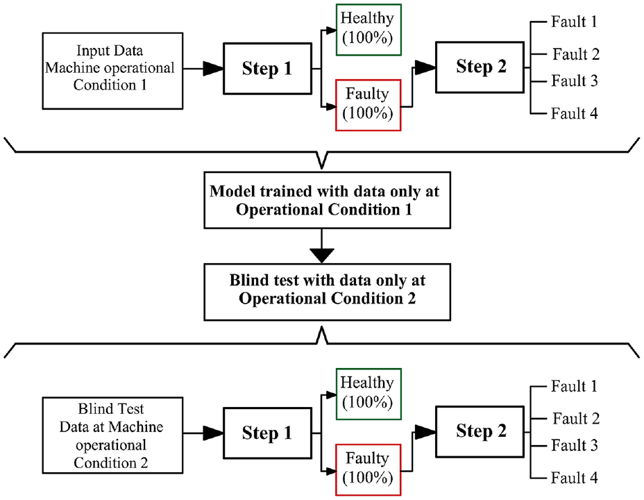
Flowchart for the blind application of the two-step approach.
Experimental rig and data
The details of the experimental rotating rig and the measured vibration data 12 for the different machine conditions at two different machine speeds are presented here.
Experimental rig
The rig in Figure 4 is made by two shafts Sh1 and Sh2, rigidly coupled, mounted through four ball bearings B1–B4, mounted on the identical flexible pedestals P1–P4. The lengths of the shafts Sh1 and Sh2 are 1.0 and 0.5 m, respectively. The machine has three identical balancing discs: D1 and D2 mounted on Sh1 and D3 mounted on Sh2. The driven end, on Sh1, is connected to an electric motor by a flexible coupling, C1. By this, no influence from the motor is transferred to the collected signals. The photograph of the rig is shown in Figure 5, where the heavy steel frame acts as the machine rigid base platform.
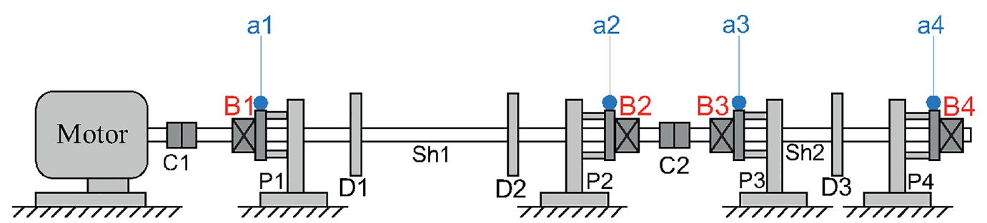
Schematic of the experimental rig. 15
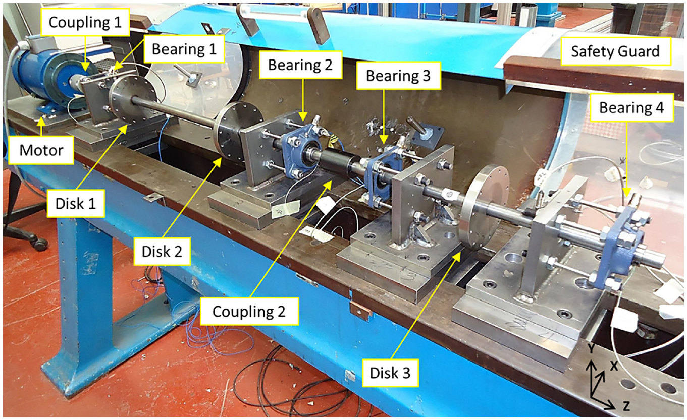
Experimental setup of laboratory rig. 15
Experimental data
The available measured vibration acceleration 12 data are collected at a sampling frequency of 10,000 samples/s by four accelerometers, shown as a1–a4 in Figure 4. These sensors are located at the bearing housing, and they acquire the vibration signals simultaneously at the four measuring locations. The length of each sample is 5 s.
The experimentally simulated faults are considered to occur in the machine independently from each other. However, it is important to notice that the machine is subject of residual misalignment and residual unbalance for all the studied conditions. All the experimentally simulated faults are rotor-related defects, typically occurring in industrial applications, that is, misalignment, shaft bow, looseness in bearing pedestal and rotor rub. Typical experimental velocity spectra for these rotor faults are shown in Figure 6. Different features of the harmonic and subharmonic frequency peaks are observed for the different fault conditions as expected.
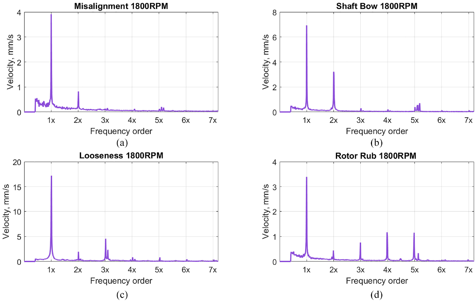
Typical experimental velocity spectrum plots from data at 1800 RPM, at B3 location: (a) misalignment, (b) shaft bow, (c) looseness in pedestal and (d) rotor rub.
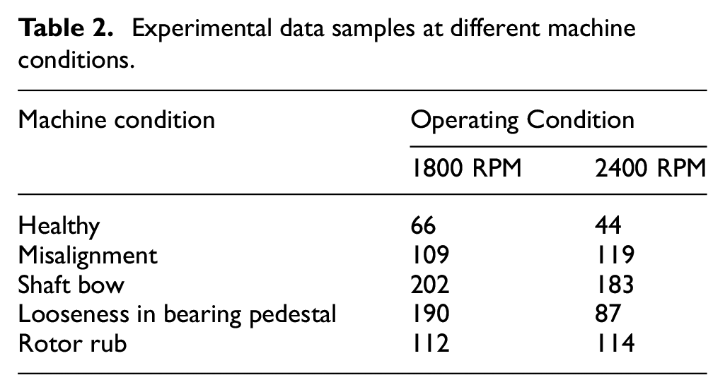
A random number of samples are generated for each rotor condition and each operational speed included in the study. The speeds are 1800 RPM or 30 Hz and 2400 RPM or 40 Hz. The details of the vibration samples collected are listed in Table 2.
Experimental data samples at different machine conditions.
Observations and results
The machine speed of 1800 RPM (30 Hz) is considered as Operating Condition 1 and the speed of 2400 RPM (40 Hz) as Operating Condition 2. The proposed two-step approach section ‘ML Model’ is first implemented onto the experimental data samples at Operating Condition 1 (1800 RPM). The trained ANN-based model and the two-step approach as in Figure 2 at Operating Condition 1 (1800 RPM) are then tested blindly with the data collected at Operating Condition 2 (2400 RPM), as shown in Figure 3. The observations and results are discussed in the following sections.
Operating Condition 1
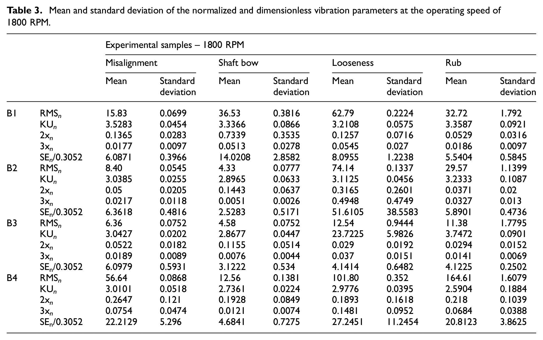
The measured vibration acceleration data samples at Operating Condition 1 (1800 RPM) are analysed in both time and frequency domains to estimate the normalized vibration parameters listed in Table 1. The parameter data bank is constructed as per Equations (1)–(3) for both healthy and all faulty machine conditions. The mean and the standard deviation of the normalized parameters (dimensionless) for all the samples are listed in Table 3. The healthy machine condition shows dominant 1× component, and hence, the faulty condition data are only shown in Table 3. The data bank in Equation (3) for each machine condition is then randomly divided into three groups – 70%, 15% and 15%. The 70% data are used to train the Step-1 ANN model. The healthy machine condition data are then removed from the data bank to train the Step-2 ANN model as per Figure 2. The remaining random 15% and 15% data from the data bank are used for the validation and testing of the trained models at Operating Condition 1.
Mean and standard deviation of the normalized and dimensionless vibration parameters at the operating speed of 1800 RPM.
It is observed that the accuracy of the ANN models at both steps is found to be 100% at all stages (training, validation and testing). The performance is calculated using Equation (4). These results are represented in Figures 7 and 8, respectively. This means that the proposed two-step approach is capable to identify the machine conditions accurately in the following steps.
(1) Step 1: healthy or faulty machine with 100% accuracy (Figure 7). This is important information for the management and operational teams.
(2) Step 2: predicting exact nature of the fault (Figure 8). This is essential information for maintenance within any industries to plan the remedial action to avoid unplanned shutdown.
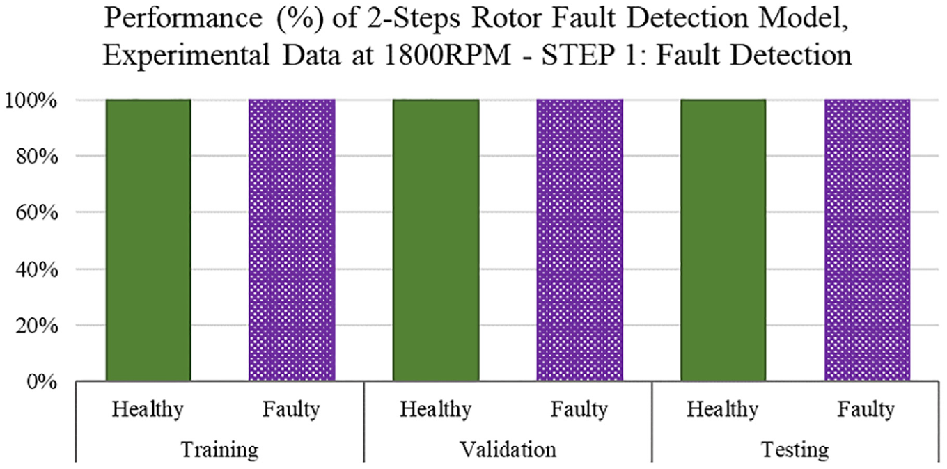
Performance of Step 1: fault detection of the proposed smart model during training, validation and testing. Experimental data only at 1800 RPM.
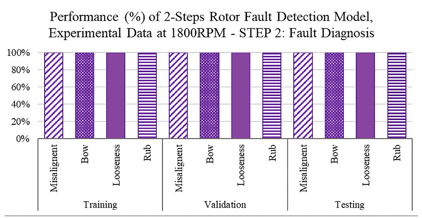
Performance of STEP 2: fault diagnosis of the proposed smart model during training, validation and testing. Experimental data only at 1800 RPM.
This observation confirms that the simple ANN model proposed in the earlier study 15 is sufficient to identify the machine condition accurately if the input parameters are used based on the dynamics of the machines. 17
Blind test at Operating Condition 2
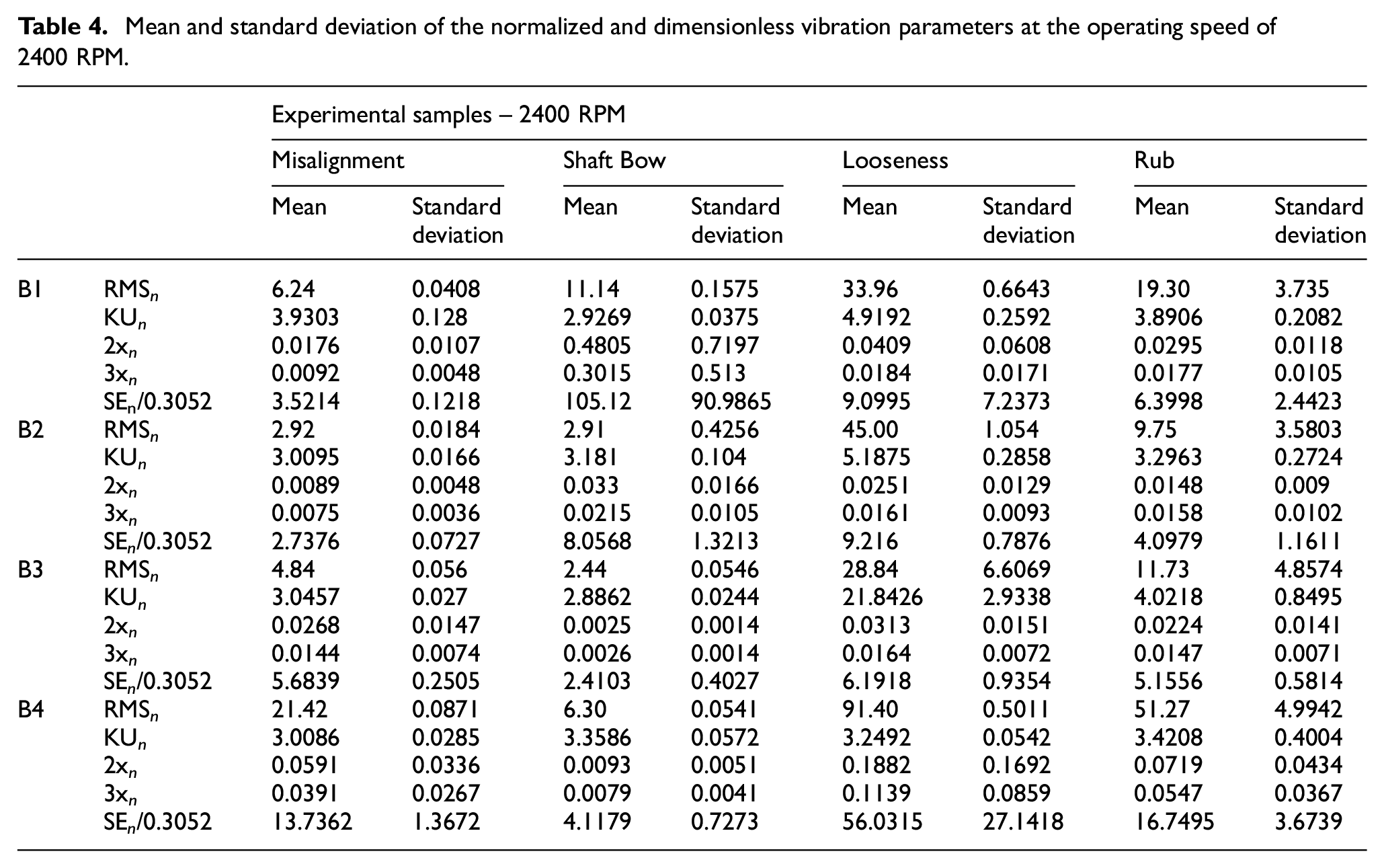
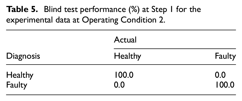
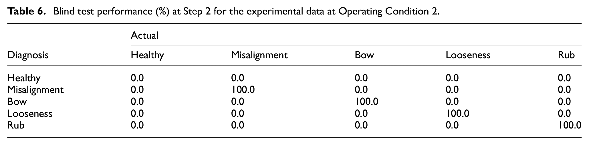
A number of identical machines are used within an industry and worldwide, but their dynamics may be different due to different operating conditions. Hence, the trained models in section ‘Operating Condition 1’ should be applicable. The trained two-step models are applied blindly to Operating Condition 2 with the machine operating speed of 2400 RPM (40 Hz). The dynamic behaviour of the rig is likely to be different compared to the machine speed of 1800 RPM (30 Hz). The total samples of 44 (healthy), 119 (misalignment), 183 (bow), 87 (looseness) and 114 (rub) at the machine speed of 2400 RPM in Table 2 are tested, and diagnosis is found to be 100% accurate. The mean and the standard deviation of the normalized parameters (dimensionless) for all the samples are listed in Table 4. The obtained results for steps 1 and 2 are listed in Tables 5 and 6, respectively. The results are excellent as the model has the capacity of identifying the actual machine state even when the operating condition is different. The ability of performing accurately of the approach allows one to integrate and unify information among the plant as well as to standardize the criteria used to conduct the fault detection and decision-making process. This study also confirms that the normalization of vibration-based parameters with the unbalance responses can minimize the deviations in the dynamics behaviours of the identical machines even with the different operation conditions.
Mean and standard deviation of the normalized and dimensionless vibration parameters at the operating speed of 2400 RPM.
Blind test performance (%) at Step 1 for the experimental data at Operating Condition 2.
Blind test performance (%) at Step 2 for the experimental data at Operating Condition 2.
Theoretical validation
An FE model of the studied experimental rig has been developed,14,18 aiming to better understand the dynamics of the machine as well as to validate the proposed approach. The studied rotor conditions are simulated into the FE model in order to generate the vibration data samples.
FE model and data simulations
The FE model of the rig is shown in Figure 9.14,18 The rotor is modelled using two-node 150 Timoshenko beam elements, as shaft line model. 18 The four degrees of freedom (DoFs) corresponding to the two bending displacements and two bending rotations are used at each node. Mathematically, the responses at the ith node corresponding to four DoFs are denoted by the two translations, ui and vi, and two bending angles, θi and ψi, in the horizontal and vertical directions, respectively.
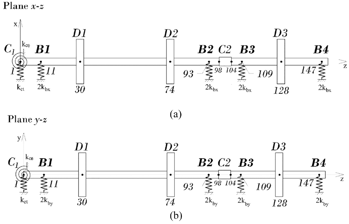
The coupling mass effect and spring stiffnesses corresponding to both translational and rotational spring effects of the coupling are also included in the FE model. Similarly, the disc effects (both mass and inertia) and the bearing mass with housing at each bearing location are also included in the FE model. Simple springs are added at the bearing locations to incorporate the bearing pedestal stiffnesses. The stiffness values at the supports are adjusted to match the first and second natural frequencies of the experimental rig, 50.66 and 56.76 Hz.12,18 The dynamic equation of motion of the rig at time t is written as in Equation (5)

where
Summary of the different faults simulations in the FE model.
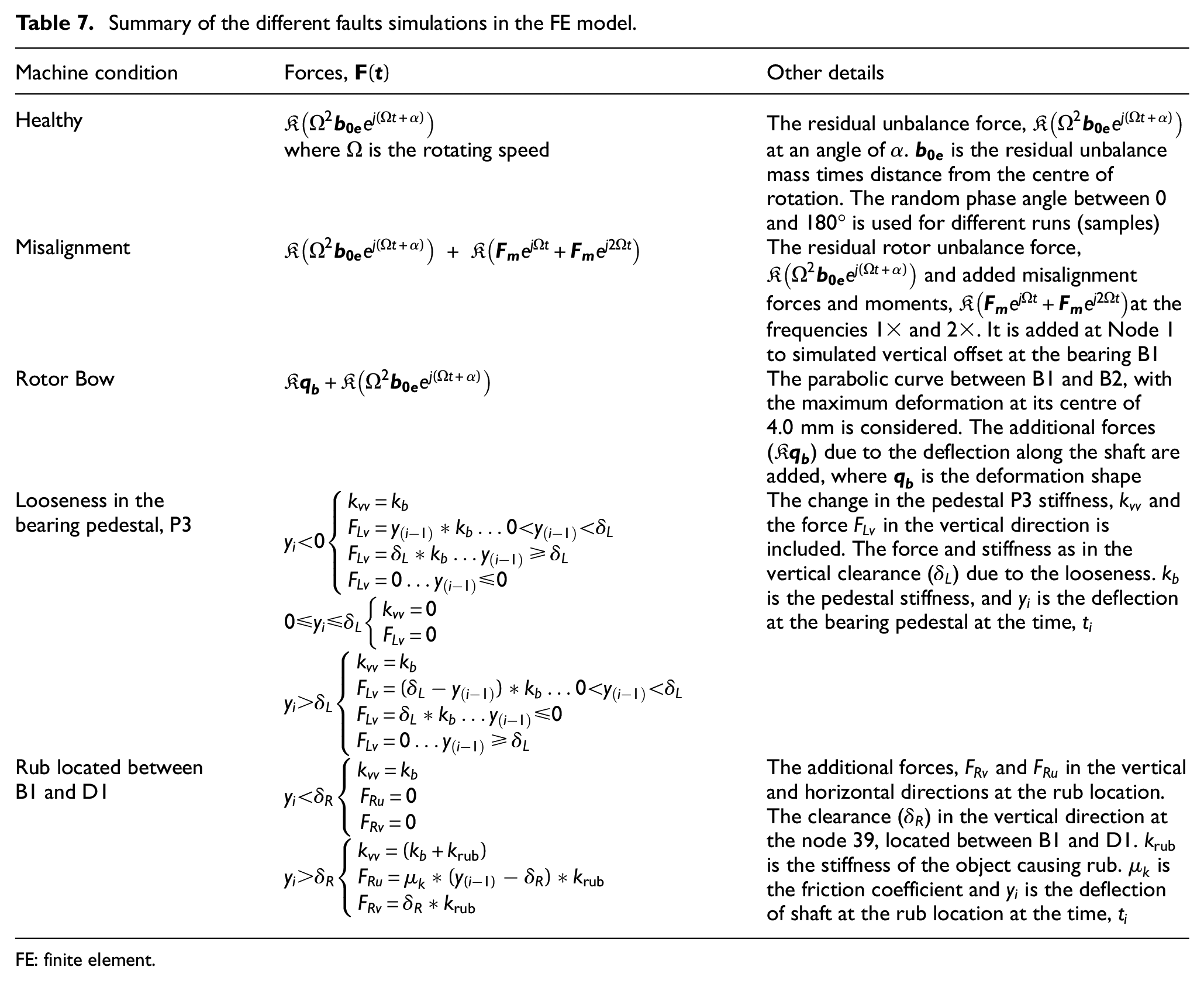
FE: finite element.
The acceleration responses at the bearing locations similar to the experiments are estimated using Equation (5) for different machine conditions (both healthy and different faulty cases). The Newmark-β integration method20,21 is used for response estimation. The time step of 1/10,000 s is used to have the sampling frequency of 10 kHz (same as experiments). The acceleration responses are estimated at both rotating speeds, 1800 and 2400 RPM. The unbalance phases at the balancing discs are randomly changed in the range of 0–180° to simulate the different starts (sample) of the machine. The steady-state responses similar to the experiments are only considered here. The random noises with a signal-to-noise ratio of 30 dB are also added to the estimated responses.
Two-step model validation
Initially, similar to the experiments, the data bank is generated as per Equation (3) for the FE simulated vibration data at the speed of 1800 RPM (30 Hz). Then, the data are randomly grouped into 70% for training, 15% for validation and 15% for testing at both of the steps. This means that for the first step, all the available data are used in the process. For the second step, fault diagnosis, the samples identified as faulty during the first step are used to feed and train the second ANN model. Similarly to the experimental observations, here also, an accuracy of 100% is observed at both the steps for all the three training stages (training, validation and testing) for the data generated only at 1800 RPM. This confirms that the vibration-based parameters based on the rotordynamics reflect the machine conditions appropriately.
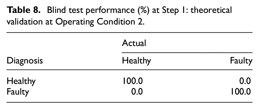
First, both the ANN models are trained at the machine operating speed of 1800 RPM; then, both the models are blindly applied to the theoretical data simulated at the second Operating Condition, 2400 RPM (40 Hz). The obtained performances for Steps 1 and 2 are listed in Tables 8 and 9, correspondingly.
Blind test performance (%) at Step 1: theoretical validation at Operating Condition 2.
Blind test performance (%) at Step 2: theoretical validation at Operating Condition 2.
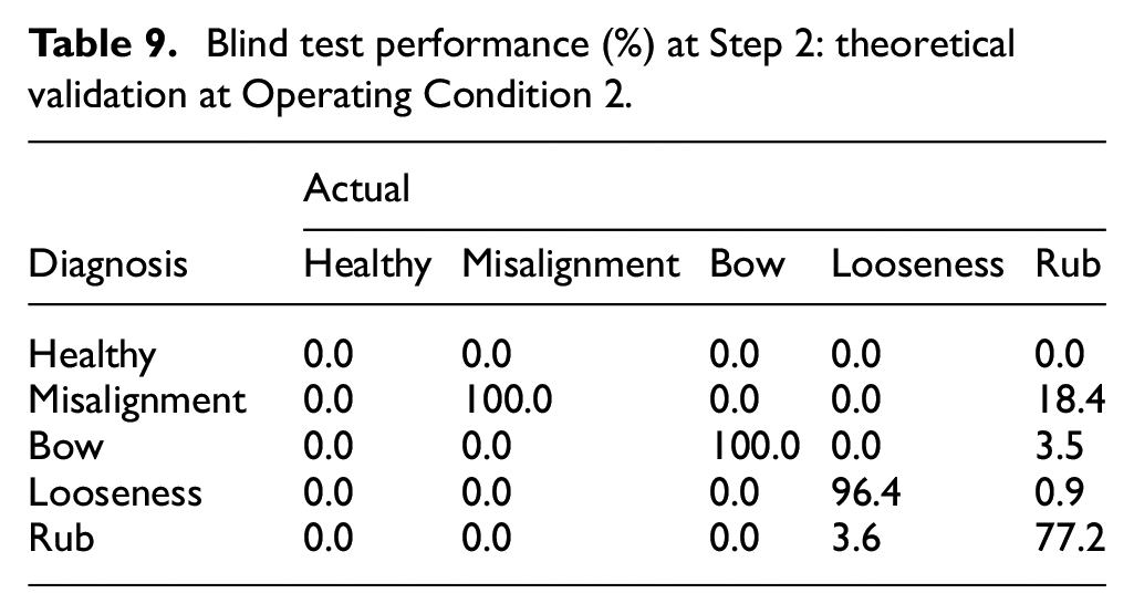
As experiments, an accuracy of 100% is observed at Step 1 for blind application. However, a few samples of the rub machine condition mainly are diagnosed as the other faults in Step 2. The data generated thought the FE model may not be exactly identical as the experimental dynamics behaviours. Thus, in some cases, rub behaviours are like misalignment, and other faults. Hence, a more accurate FE simulation may be needed. However, this study confirms that the proposed normalized vibration-based parameters based on the rotor dynamics and the ANN models in the two-step approach are accurate enough to use in the industries. It is remarkable that the model is consistent in separating the faulty samples from the healthy samples with an accuracy of 100% during the validation process even when samples from a different operational condition are analysed. This skill is highly important for industrial application, where the identification of a faulty machine at an early stage is crucial to avoid potential catastrophic effects related to health and safety, production and environment, among others.
In Figures 10 and 11, the results obtained at both steps when using experimental data are compared against the results during theoretical validation. Figure 10 shows how both data sets delivered an accuracy of 100% to separate the faulty samples from the healthy ones. Figure 11 shows the performances in detecting each fault type during Step 2. A little inaccurate fault diagnosis is mainly observed for the rub condition for the FE simulated data. The FE simulation may need to improve to reflect the experimental rub behaviour. However, this FE model is good enough to test and validate the proposed two-step approach.
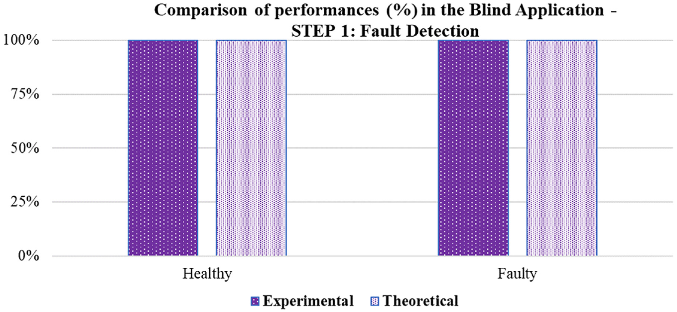
Comparison of performances (%) at Step 1 of the model’s blind application between the experimental and theoretical data.
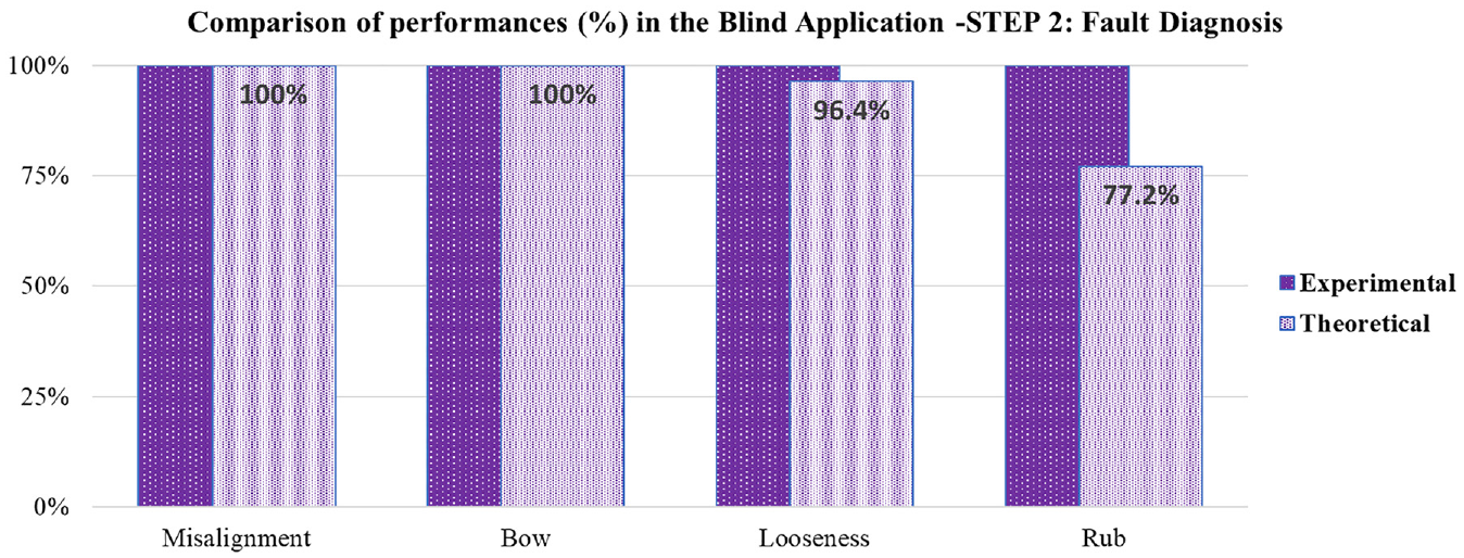
Comparison of performances (%) at Step 2 of the model’s blind application between the experimental and theoretical data.
Concluding remarks
A smart rotor fault detection and diagnosis model is developed and applied in a two-step approach. This method considers the vibration signals from both time and frequency domains in order to accurately characterize the dynamics of the machine. A multilayer perceptron ANN is used to perform the pattern recognition and establish the correlation between the input vibration samples and the healthy status of the machine. The vibration-based parameters based on rotordynamics are considered for this development. These parameters are normalized to reduce the impact of the rotor unbalance response so that the deviations of the identical machines dynamic behaviours within any industry can be reduced. The two-step approach is then developed on a machine that can be used blindly for other identical machines. The proposed method is developed initially on an experimental rig at an operating condition and blindly tested on another operating condition. The first step identifies the machine condition (healthy or faulty). This is vital information for the operation and management teams within any industries. All identical machines with an industry can be quickly assessed at the first step of the proposed method. The second step is then used to identify the exact nature of fault in the machine so that the maintenance team can plan further for the remedial action. An accuracy of 100% on the diagnoses at both steps is observed.
The proposed method is also validated through a mathematical FE model using the calculated vibration acceleration responses with noises, simulating all the experimental rotor conditions. Hence, the proposed two-step approach using the ANN model and the normalized vibration-based parameters selected on the basis of rotordynamics is observed to be useful for industrial applications.
Footnotes
Acknowledgements
Natalia Fernanda Espinoza Sepúlveda acknowledges the support by CONICYT (Comisión Nacional de Investigación Científica y Tecnológica/Chilean National Commission for Scientific and Technological Research) “Becas Chile” Doctorate’s Fellowship programme; Grant No. 72190062 for her PhD study.
Declaration of conflicting interests
The author(s) declared no potential conflicts of interest with respect to the research, authorship, and/or publication of this article.
Funding
The author(s) received no financial support for the research, authorship, and/or publication of this article.