
Abstract
It is essential to continuously monitor the spall size of wind turbine pitch bearings to prevent severe faults and catastrophic failure. In the field of spall size estimation for bearings, an essential step is to extract the entry and impact signals simultaneously. And this would become more difficult when it comes to the wind turbine pitch bearings due to the limited fault signals and heavy noise. In this paper, a coherent procedure is proposed to estimate the spall size for wind turbine pitch bearings. Firstly, the characteristics of entry and impact signals in actual wind turbine pitch bearings are observed to be low-frequency and high-frequency dominated, respectively. On the basis of characteristics analysis, a novel two-stage signal processing method called the wavelet augmented sparse dictionary, is proposed to extract the entry and impact signals, which combines the discrete wavelet transform and sparse representation technique. Finally, the spall size is calculated according to aforementioned extraction and geometric constraints. Results from real-world experiments demonstrate the effectiveness of the proposed method.
Keywords
Introduction
Background
Wind power is one of the fastest-growing energy sources 1 due to its clean and pollution-free characteristics. 2 Quite a few wind farms are located in isolated areas with harsh landscapes, such as mountains or offshore environments. The harsh environmental conditions, characterized by strong winds and low temperatures in mountainous regions, coupled with corrosion and heavy rainstorms at sea, render the components of a wind turbine (WT) system, such as the blades, bearings, gears, and generator, particularly prone to failure.3–5 To keep normal operation and ensure the energy yield of a wind farm, the maintenance of WTs is crucial, 6 and pitch bearings, as important support components in WT systems, require particular attention. 7 Regarding the maintenance of WT pitch bearings, there is often a significant time lag between the initial detection of a defect and final failure. This situation results in spall size (raceway pitting) estimation is essential because it can help field engineers determine the specific level of damage to a WT pitch bearing and schedule a replacement at an appropriate time. In addition, to augment detection accuracy, certain state-of-the-art WT pitch bearings have been engineered to release limiting stoppers, thereby enabling a complete 360° rotation during the maintenance process. 8 This innovative design feature significantly facilitates maintenance activities. Consequently, this paper concentrates its research efforts on estimating spall size specifically for WT pitch bearings capable of a full 360° rotation.
To thoroughly understand the spall size, this paragraph would explain the fault signals that are generated due to the existence of spall. Figure 1 illustrates the fault signals in general bearings. When the ball of a bearing crosses a spall defect, which is depicted as a rectangular profile on the bearing race surface, two bumps may occur. The first bump with dominated low-frequency characteristics is generated from the entry point, and the second one with dominated high-frequency characteristics is triggered from the impact point. 9 By extracting the intervals of the fault signals resulting from the two bumps, the spall size of the bearing can be subsequently estimated. 10
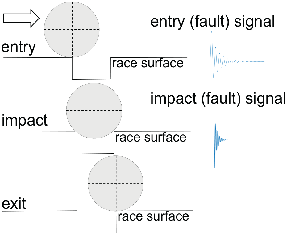
Demonstration of occurring fault signals associated with entry and impact events.
Literature review
Regarding the estimation of spall size for bearings, Epps 11 initially identified the issue of spall size and studied the periodic forcing and vibration of bearings and surrounding structures caused by vibration sources when bearings encounter discrete faults. After the research of Epps, other research has concentrated on two directions: the dynamic model and signal processing. The analysis of a dynamic model can aid in the understanding of the underlying characteristics of the spall phenomenon. Signal processing techniques are used to extract the fault signals from collected signals, which are often contaminated with noise. The extracted fault signals can then be compared to the results of the dynamic model to validate the estimation of spall size. Below, we briefly summarize these two directions.
The dynamic model, an analytical framework incorporating elements like mass and stiffness, is capable of uncovering the inherent properties and systematic patterns of spalls. This model effectively simulates vibration response signals corresponding to various spall sizes. Kogan et al. 12 introduced a multi-body, nonlinear dynamic model to evaluate spall size in radially loaded rolling-element bearings, enhancing the understanding of bearing damage severity and aiding in the estimation of remaining useful life. Sawalhi and Randall 13 proposed a dynamic model with five degrees of freedom, accounting for object slippage. Singh et al. 14 developed a nonlinear dynamic model to investigate physical excitation mechanisms and spalling defects. Zhang et al. 15 presented an index method for measuring the magnitude of full-scale faults in the inner race. Luo et al. 16 took significant factors into account in dynamic models, including transient impact force, stiffness, and damping under elastohydrodynamic lubrication conditions. Overall, these dynamic model methods analyze and model the physical process of spall from different perspectives, helping to characterize the actual evolution pattern of spall.
In engineering practice, the direct application of dynamic models presents challenges due to their complexity, high data requirements, issues with reliability and accuracy, computational demands, real-time application difficulties, and the need for specialized user training and understanding. With the development of signal measurement devices, the observation of fault signals has become easier than before. This situation has led some scholars to study signal processing methods for spall size estimation. Sawalhi and Randall 9 proposed two strategies for extracting weak fault signals related to entry and impact events. The first strategy involves the use of pre-whitening and wavelet analysis to maintain a balance of energy between low and high-frequency components when the bearing ball passes through the spalls. The second strategy deals with the two peaks resulting from the entry and impact events separately to represent them equivalently. The power cepstrum is used to estimate the average interval between the two peaks. This signal-processing technique can effectively segregate the two peaks corresponding to the entry and impact events, respectively. Smith et al. 17 proposed a sophisticated method for determining the entry point by introducing two assumptions. The first assumption is based on the low-pass filtered acceleration gradient crossing zero, while the second assumption locates the entry point at the peak of the low-pass filtered acceleration. Sawalhi et al. 18 introduced a signal processing technique for estimating spall sizes in rolling element bearings, utilizing autoregressive inverse filtration and synchronous averaging of bearing signals. This method enhances weak step response events and balances them with prominent impulse responses, proving more effective than existing algorithms by providing accurate spall size estimations without the need for additional processing like wavelets. Chen and Kurfess 19 proposed a signal processing method that combines the variational mode decomposition, cross-correlation algorithm, and squared differential algorithm to determine the timestamps of entry and impact points from the collected bearing vibration signal. This allows for the calculation of spall size.
Methodology overview
Based on the literature review presented above, it is clear that research has been conducted on spall size estimation for small-size general bearings, which are often rotated at a speed of several hundred rpm or more. However, when it comes to this specific WT pitch bearings, the spall size estimation may not be directly applicable. This is because the slow rotated speed (such as 1 rpm) of WT pitch bearings may increase the difficulty of size estimation. Although the rotation is very slow, the sampling frequency is high (e.g. 10 kHz) in order to capture the major vibration mode. Given a fixed amount of sampling time, the high sampling produces a large number of data but they only contain a small number of fault signals. More specifically, for a pitch bearing with 60 balls rotating at 1 rpm, 1 min data (10 kHz * 60 s) with a sampling of 10 kHz has only 60 fault signals. The ratio of the fault signal number to the full data, namely 60/10 kHz * 60 s = 1/10k, is very low. This low ratio makes their detection and extraction very challenging. The challenges of spall size estimation for WT pitch bearings can be summarized as follows:
The authors of the current work did not find any publications specifically addressing the estimation of spall size in WT pitch bearings. This is mainly because wind power has only been widely exploited over the last few decades, and the damage to the pitch bearings may take a very long time (such as 10 years or even more). This is an issue that has rarely been studied before.
Extracting entry and impact signals accurately from noise-contaminated raw signals is difficult. The number of fault signals, that is, entry and impact signals, is limited due to slow rotation, which makes the proportion of fault signals in the total signal extremely low, compared to the high-rotating-speed bearings.
For the first challenge, a test-rig for the full-scale pitch bearing was set up, and the pitch bearing has been operated in a real wind farm for over 15 years, and the spall was formulated during its operation in the real wind farm. This spall was naturally incurred instead of artificial introduction.
In addressing the second challenge of extracting limited fault signals, it is essential to refer to research on general bearings while concurrently considering the unique characteristics of WT pitch bearings. Referring to Refs. 9, 17 and 19, two treatments to eliminate noise and extract fault signals can be summarized, namely one-off extraction and progressive extraction, respectively. In contrast to one-off extraction, progressive extraction of both entry and impact signals simultaneously may not be as expeditious or straightforward, but it can effectively capture extensive quantities of fault signals. 9 In the case of high-speed general bearings with numerous fault signals, disregarding a small number of them may be inconsequential. However, as mentioned in the second challenge, a full-scale, low-speed rotating bearing, WTs inherently generate fewer fault signals, which makes them more sensitive to the omission of fault signal capture. 20 Hence, considering the second challenge, the adoption of progressive extraction is specifically preferred in this paper for fault detection in WTs.
In accordance with the progressive extraction structure, this paper presents a two-stage approach for progressive signal processing. The first stage utilizes the wavelet transform method to suppress high-frequency noise, which has been proven effective21–23 in numerous bearing fault diagnosis applications. Thus, the clarity of relevant fault signals is enhanced and the likelihood of eliminating fault signals as noise during the second stage processing is reduced. The second stage centers on the sparse representation (SR) technique, which is a widely used method for bearing fault signal extraction due to its excellent convergence and interpretability24,25 and has also been proven effective in signal processing for WT bearings.7,26
Nevertheless, SR may ignore quite a few fault signals, 27 which is not conducive to capturing the limited fault signals described in the second challenge. Especially in the task of estimating spall size, the difficulty of fault signal capture is significantly increased when identifying both entry and impact signals simultaneously. 9 To minimize the number of missing fault signals, that is, entry and impact signals, a Union Orthogonal Matching Pursuit (UOMP) algorithm is employed for SR. UOMP here is a sparse pursuit method, improved according to Wang et al. 28 and Justo et al., 29 that handles over-complete dictionaries effectively. Compared with the Orthogonal Matching Pursuit (OMP) algorithm, it shows better performance in terms of robustness to noise. Hence, the UOMP is incorporated into the second stage, and the omission of fault signals could be reduced, which is helpful to tackle the second challenge.
The primary objective of the wavelet transform utilized in the first stage is to reduce high-frequency noise, which consequently improves the distinctiveness of pertinent fault signals while minimizing the probability of erroneously discarding them as noise in the second stage processing. In the second stage, the application of SR involves the implementation of a union pattern within the UOMP in conjunction with the commonly utilized Singular Value Decomposition (SVD). 30 Such integration facilitates the detection of limited fault signals mentioned in the second challenge, thereby enhancing the accuracy of the subsequent spall size calculation.
In a nutshell, this paper proposes a coherent procedure for spall size estimation on WTs, which contains the observation, signal processing method and experiments. The primary contributions could be summarized as follows:
The characteristics of entry signals (low-frequency dominated) and impact signals (high-frequency dominated) in WT pitch bearings are analyzed according to the observations from one actual pitch bearing, and the analysis results can provide physical evidence for research in this field.
A two-stage progressive signal processing approach, called wavelet augmented sparse dictionary (WASD), is designed by combining wavelet transform and SR to efficiently filter the raw collected signals and extract the fault signals associated with entry and impact events.
A naturally occurring defect in pitch bearing, which has been in operation on a wind farm for over 15 years, is used in experiments to validate our method. To the best of the author’s knowledge, this is presumably the first study to estimate spall size for one actual WT pitch bearing.
The rest of this paper is organized as follows. In section ‘Observation’, the observation process of fault signal is presented. Subsequently, section ‘Signal processing method’ proposes a signal processing method. Then section ‘Calculation for spall size’ introduces a size calculation method based on the results from signal processing. After that, section ‘Experiments and results analysis’ is dedicated to the analysis of the simulation experiments and physical experiments. Finally, section ‘Conclusion’ concludes the current work.
Observation
The characteristics of the entry and impact signals in WT pitch bearings need to be determined. Firstly, the raw signals are collected from WT pitch bearings in a state of relatively smooth operation, indicating that the data in the start and end phases are removed and only the steady phase is kept. Secondly, the basic bandwidth filter is applied to eliminate some noisy components. After careful adjustment and selection, a short signal is presented in Figure 2. In the specific field of WT pitch bearings, it can be inferred that the entry and impact signals also exhibit low-frequency and high-frequency characteristics, respectively. The findings depicted in Figure 2 indicate that the entry signals have low-frequency around 250 Hz, while the impact signals have high-frequency around 1600 Hz.
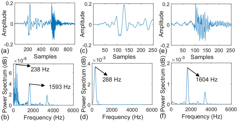
Observed signals within time and frequency domain, (a) and (b) a pair of entry and impact signals, (c) and (d) entry part, and (e) and (f) impact part.
To accurately determine the internal state of the bearing, endoscope inspection is employed to gather definitive evidence of damages. Prior to initiating the inspection procedure, it is necessary to properly clean the bearing. This includes either gentle suction or cautious wiping to eliminate surplus lubricant. It is critical to emphasize that this cleaning process must be executed with utmost care to prevent inflicting further harm to the inside of the bearing. The findings from the endoscope inspection are depicted in Figure 3, illustrating a spall length of 9 mm on the inner race.
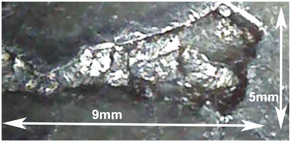
Detected defect through endoscope. 7
Signal processing method
Preliminary knowledge
Discrete wavelet transform
Discrete wavelet transform (DWT) can use different numbers of layer decomposition. Regarding the one-layer wavelet decomposition, the original signal
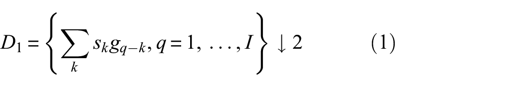
where

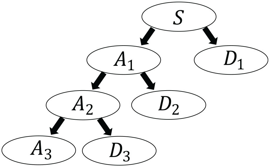
Three layers wavelet decomposition.
Sparse representation
It is given one signal
The vibration signals collected from WT pitch bearing are often made up of faulty components and noisy components. The fault components often occur when the rolling balls pass the detect, resulting in periodic impulse oscillation. The noisy components are usually generated by mechanical rotation movements, electric signals, sensor imperfections and so on. The observed vibration signal can be denoted as follows:

where
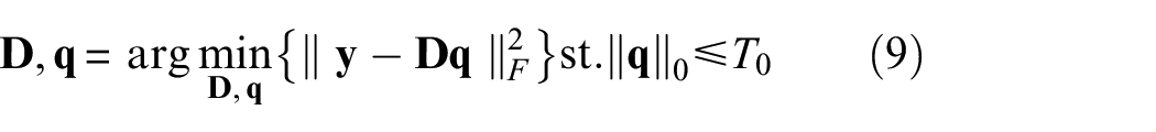
SR is a technique that can be used for fault signal extraction. Through the SR, all the components irrelevant to fault signals can be filtered to a large extent. The piece vibration signals

where

Framework of spall size estimation
As depicted in Figure 5, the collected signals undergo a two-stage processing method consisting of a coarse and fine filter. The fault signals are then extracted and used to identify the corresponding entry and impact events. By analyzing the fault signals associated with entry and impact events, the spall size can be accurately calculated.

Complete flow chart of spall size estimation.
Wavelet augmented sparse dictionary
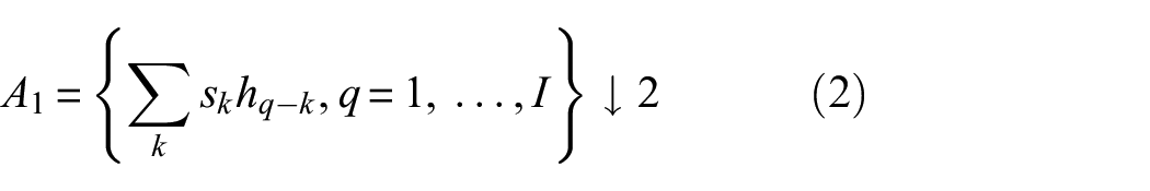
Subsequently, for the
where
The general algorithm procedures for stage I can be summarized as follows:
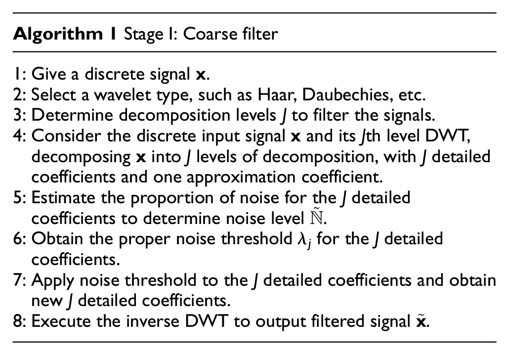
In stage I, the original signal
where
In UOMP, the pursuit of coefficient vector
In the
(1) Select the
(2) At the
(3) Obtain the least square solution:
(4) Get the residual by subtracting
As mentioned above, the updating process for converging coefficient vector
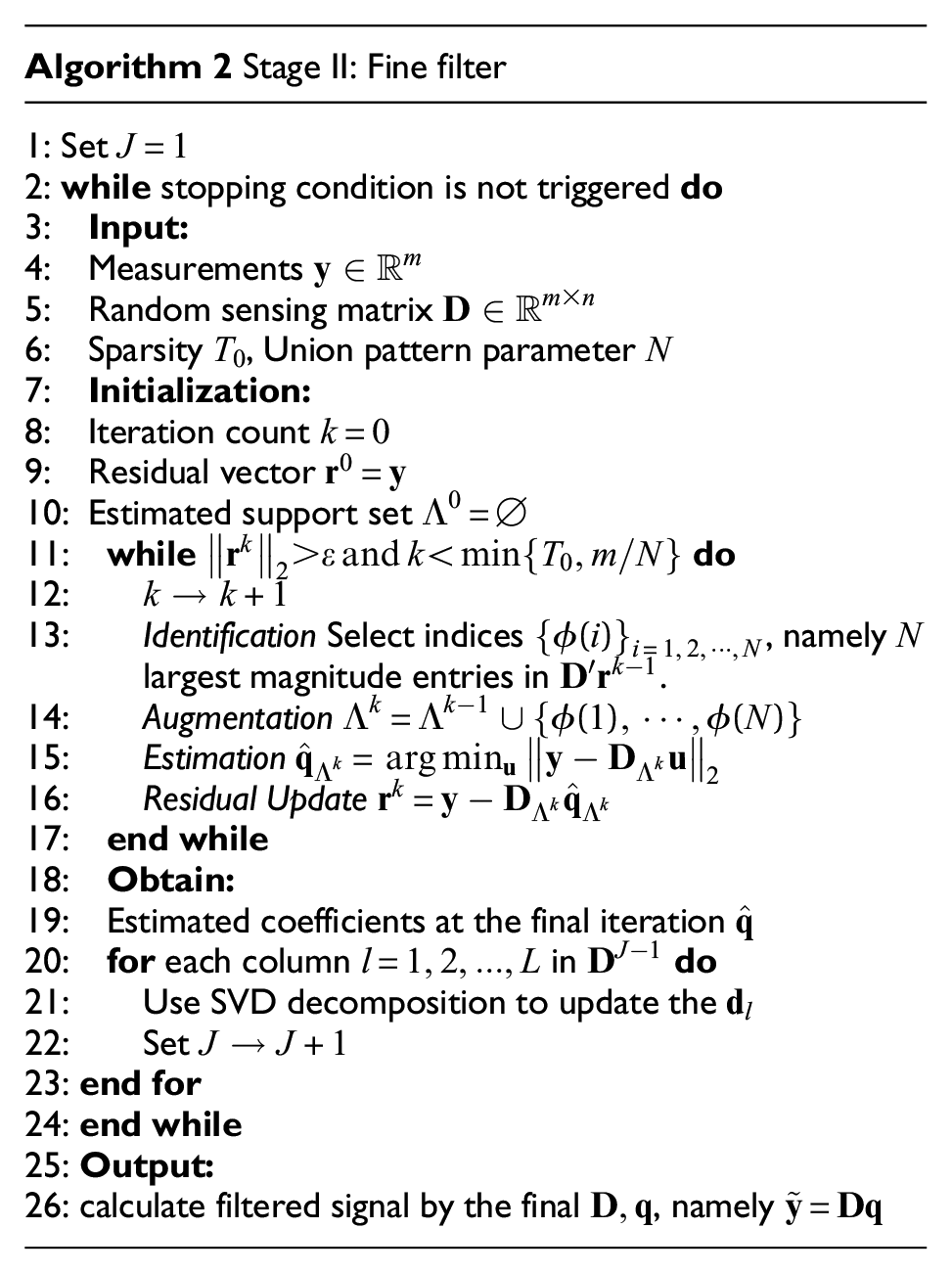
It is important to note that setting
Calculation for spall size
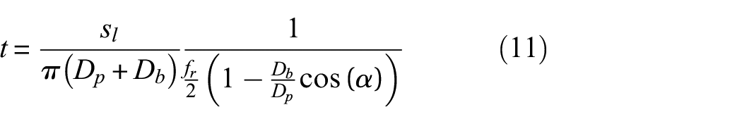
The interval to impact
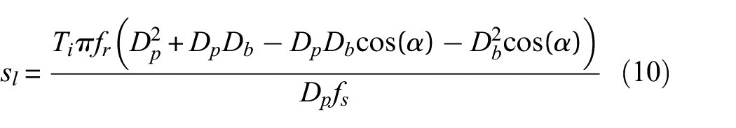
where
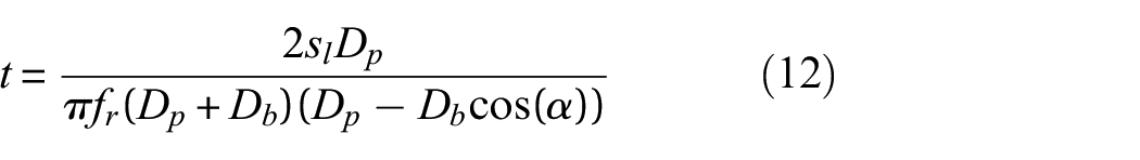
For a rolling element bearing with an outer race spall length
Through the conversion, the Equation (11) can be rewritten as:
By substituting
Experiments and results analysis
Simulated situations
As noted in Sawalhi and Randall,
9
the fault signal associated with an entry event typically exhibits lower frequency components compared to that of an impact event, which is characterized by higher frequency components. For the purpose of simulation, we represented the entry and impact events using step response and impulse response, respectively. Specifically, we represented the step response
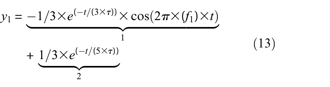
where the first component is a negative decaying cosine and the second one is an exponential function.
The impulse response

where
To simulate the noisy condition, the signal-noise-ratio (SNR) should be introduced:
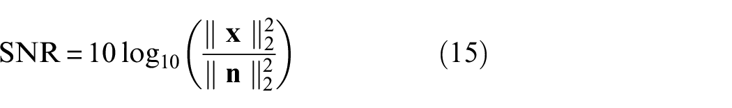
where
To simulate the slow rotation speed, it is assumed that a bearing rotates at 1 rpm, and there are 60 balls in this bearing so that the balls would pass through the defect 10 times in 10 s. A pair of entry and impact signals can be obtained by concatenating
To demonstrate the performance of the proposed method, the coarse filter only and the fine filter only are used for comparison. Figure 6 is related to time domain results from three filters. The simulated results in Figure 6(c), show that fine filter only almost missed all the entry signals, but only the impact signal is extracted. In this case, the fine filter only may not be used for spall size estimation as both entry and impact single have to be extracted simultaneously. Further, as per,33,34 the kurtosis value can serve as a performance indicator for filtering. A high kurtosis value implies the presence of multiple spikes in the filtered signals. Upon observing the change in kurtosis value, it can be observed that the result in Figure 6(e) has the highest kurtosis value of 208.3484, compared to the kurtosis of 3.0456 in Figure 6(b). The kurtosis value in Figure 6(d) is 3.5749, indicating that the first stage may reduce some high-frequency noise, enabling the second stage filter to extract the complete entry-impact fault signals.
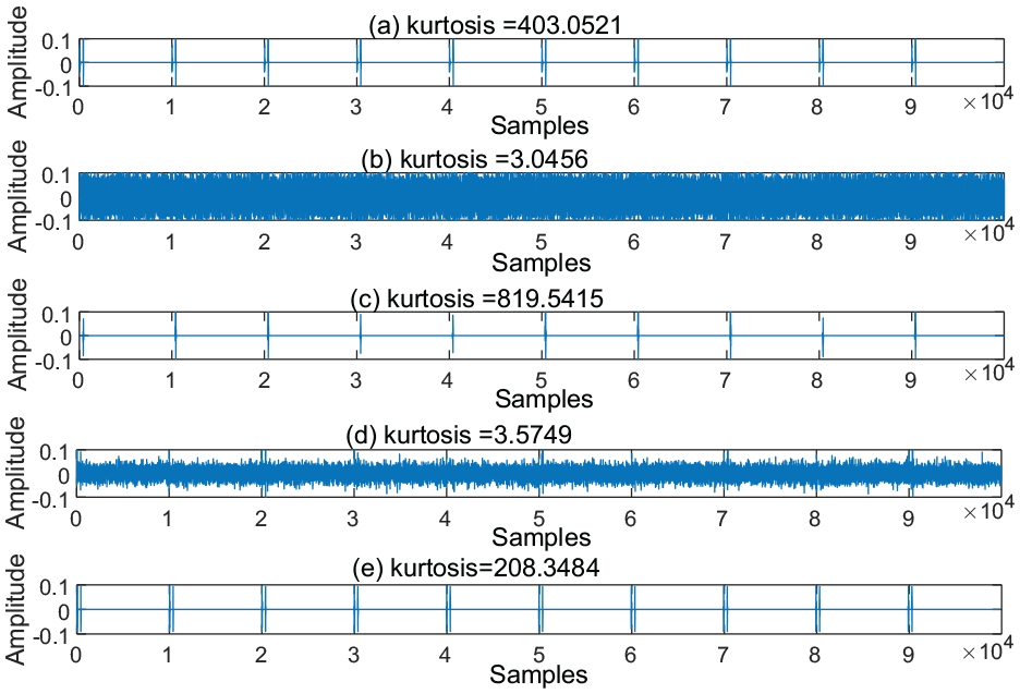
Simulation with SNR = −19.5 dB in time domain, (a) pure entry and impact signals, (b) fault signals with noise, (c) processed signals with fine filter only, (d) with coarse filter only and (e) with both coarse and fine filter.
Figure 7 shows the enlargement for Figure 6. The zoomed-in image shows that the basic dictionary method (Figure 7(b)) may lose entry signals and be difficult to calculate the spall size, but the proposed WASD method (Figure 7(c)) can well extract the interval between entry and impact signals. Additionally, the envelope technique is applied to depict the profile of a signal.
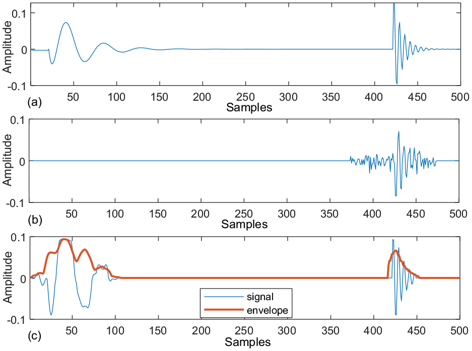
Zoomed-in results, (a) enlargement of Figure 6(a), (b) enlargement of Figure 6(c) and (c) enlargement of Figure 6(e).
A 3-D view of the short-time Fourier transform (STFT) to visualize the denoising results of our proposed WASD method is shown in Figure 8. The four figures in Figure 8 represent the STFT of Figure 6(a), (b), (d) and (e), respectively. The outcome in Figure 8(c) illustrates that the marginal shape is restored by coarse filter only, indicating that high-frequency noise has been eliminated, but the middle-low frequency components are still severely impacted by noise. The result in Figure 8(d) shows that processed signals with both coarse and fine filters, namely WASD method, contain little noise.
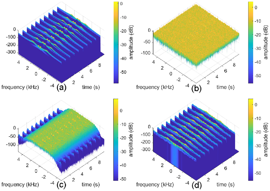
STFT for simulation with SNR = −19.5 dB, (a) STFT of Figure 6(a), (b) STFT of Figure 6(b), (c) STFT of Figure 6(d) and (d) STFT of Figure 6(e).
Physical experiments
The experiments in this research employ an industrial-scale WT pitch bearing (with a weight of 261 kg and a pitch diameter of 1 m) that has been in use for over 15 years in a real industrial wind farm. Unlike most research studies, the experiments in this paper use naturally occurring damage in a real industrial environment rather than artificially damaged or small-scale WT models. To simulate the actual operating conditions, the industrial WT pitch bearing is loaded with a real blade (with a length of 7.75 m and a weight of 139 kg), as depicted in Figure 9. The accelerometer sensor is mounted on the bearing surface to obtain the vibration signal.
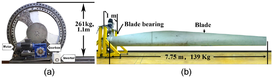
View of test-rig, 7 (a) left view and (b) front view.
To eliminate the influences of variable speed spall size estimation, the experimental data during the start and end phase was removed manually and only the data under the constant rotating speed was used.
The raw signals were collected at a sampling frequency of 10 kHz in the experiments. Figure 10(a) presents the raw signals exhibiting a kurtosis value of 165.0694. The first stage of the coarse filter focuses on removing high-frequency background noise, such as burrs on the surface of the signals, which leads to a slight increase in the kurtosis value to 198.9245, as seen in Figure 10(b). The kurtosis value of 696.0335 after the fine filter processing indicates the superior filtering performance of our proposed WASD algorithm, as demonstrated in Figure 10(c).
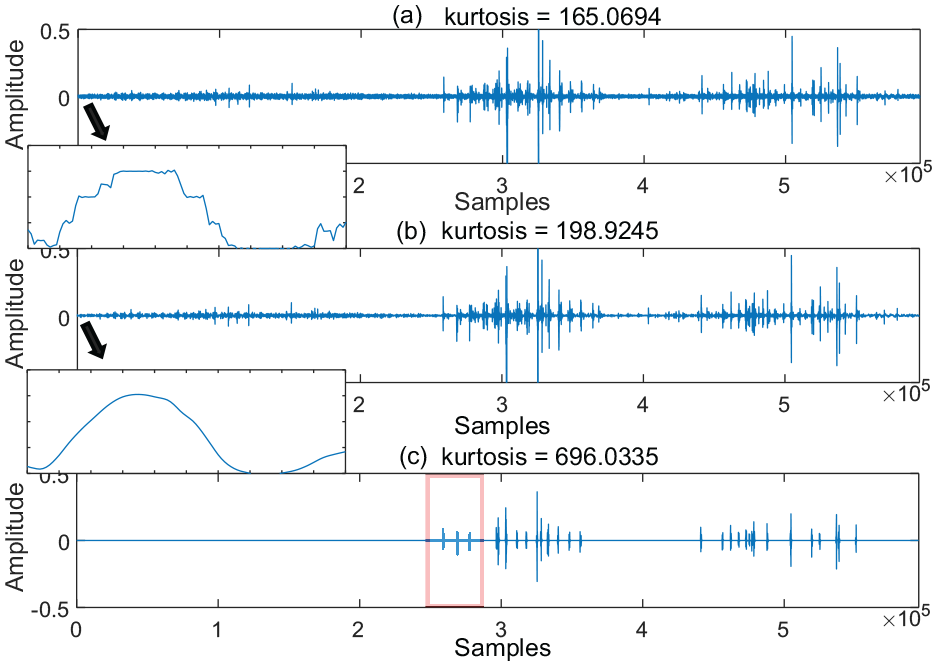
Rotating speed 4.1 rpm: (a) raw collected signals, (b) processed signals with coarse filter and (c) further fine filter.
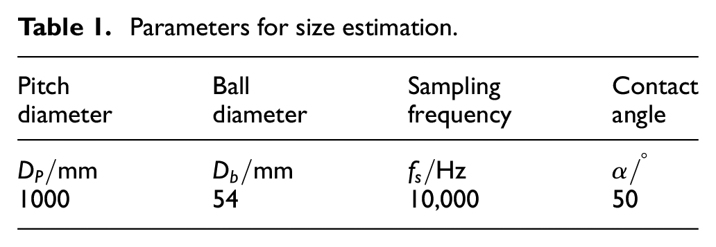
To clearly observe the performance of extracting entry and impact signals, the first three detected entry-impact events are magnified and presented in Figure 11(a). To facilitate the calculation of the spall size, envelope technique is applied when obtaining the interval between the entry and impact points, resulting in Figure 11 with a clear interval of 409. Using (10) with the bearing parameters from Table 1 and the rotating speed of 4.1 rpm, the spall size is estimated to be 8.7546 mm, which is close to the real size in Figure 3.
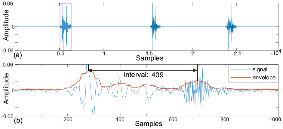
Zoomed-in results, (a) the local enlargement of the first three detected entry-impact events in Figure 10(c) and (b) the envelope of zooming in first entry-impact events in Figure 11(a).
Parameters for size estimation.
In order to further test the signal extraction performance of the proposed WASD method on other datasets, we adopted a dataset (https://data.mendeley.com/datasets/chwhh9n3bf/2) of general bearings and use the data with spall lengths of 2.1 and 3.8 mm on the inner race. Figure 12(a) and (b), respectively show the spalls with lengths of 2.1 and 3.8 mm. It can be observed that both the entry event and the impact event can be effectively detected.
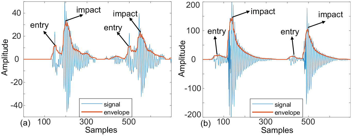
Detection test of entry-impact event in another dataset, (a) spall with length 2.1 mm and (b) spall with length
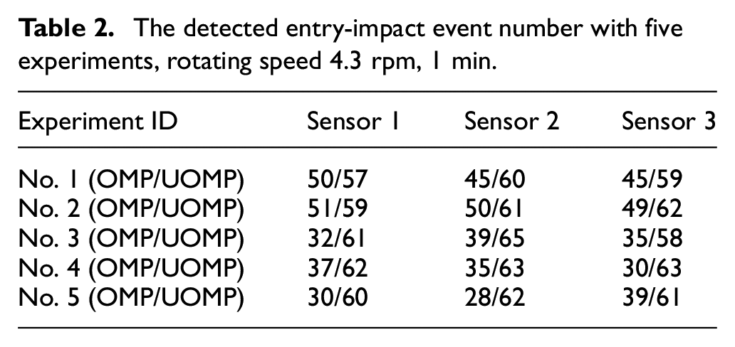
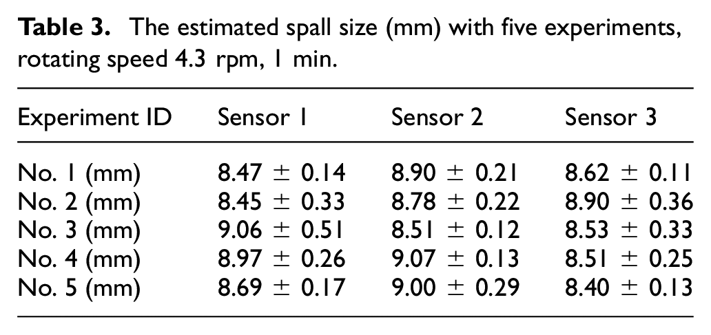
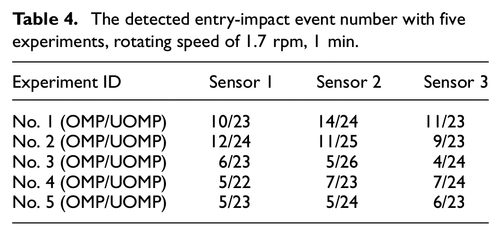
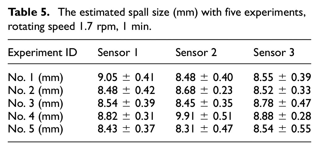
To reduce stochastic error, multiple experiments are necessary. Additionally, a comparison of the number of detected entry-impact signals using UOMP and OMP is presented here, which could validate the effectiveness of applying UOMP to extract more fault signals. Each data collection contains information from three sensors located in different places, and the code is run five times for consistency. The data was collected at a sampling frequency of 10 kHz, and a duration of 1 min was chosen for the purpose of comparison. The number of detected entry-impact events is listed in Tables 2 and 4, and the calculated results are shown in Tables 3 and 5 with mean values and variances. According to the observed size 9 mm in Figure 3, the average accuracy of spall size estimation is around 8.7/9 = 97%.
The detected entry-impact event number with five experiments, rotating speed 4.3 rpm, 1 min.
The estimated spall size (mm) with five experiments, rotating speed 4.3 rpm, 1 min.
The detected entry-impact event number with five experiments, rotating speed of 1.7 rpm, 1 min.
The estimated spall size (mm) with five experiments, rotating speed 1.7 rpm, 1 min.
Discussion
Concerning the generalization to larger bearings: Our method, currently validated for bearings with a diameter of 1 m, is applicable to larger bearings, potentially several meters in diameter. Larger bearings may simplify spall size determination for two reasons. Firstly, bearings with a larger pitch can generate more pronounced vibration signals for a given spall size due to the increased loads from larger turbine blades. This is based on the premise that larger blades exert greater forces, leading to a different load distribution within the bearing assembly. This enhanced vibration makes it easier to detect impulse signals compared to those from smaller bearings. Secondly, bearings with a larger pitch tend to have more balls than their smaller counterparts, resulting in more frequent impulse events as each ball contacts the spall over a given rotation angle, allowing for a more comprehensive analysis with repeatable impulse signals.
Regarding the sensor placement, optimal sensor positioning is crucial for effective signal acquisition. In our experiments, we employed multiple sensors and selected the one yielding the most significant signals. This approach is also practical for larger bearings. If only one sensor is available, repeated measurements at different locations are necessary to identify the location producing the most significant analysis-worthy signal.
Regarding the practical application of our proposed method: As discussed in the introduction, bearing failure can progress over an extended period, from initial spall to complete failure. Monitoring spall size is vital for tracking damage progression and determining the optimal time for bearing replacement, thereby preventing catastrophic failure. Our method offers the capability to detect spall sizes at either fixed or variable intervals. By providing engineers with these precise spall sizes, they can make well-informed decisions, taking into account the unique operational conditions and applying their engineering expertise. Additionally, other methods, like grease analysis, can be integrated to inform final replacement decisions. Furthermore, our research begins with establishing a method for detecting a single spall, a critical step towards tackling the more complex challenge of multiple spall occurrences. Future work will focus on adapting this method to identify and analyze the intricacies of bearings with several spalls, addressing both theoretical and practical needs in health monitoring.
Conclusion
This paper researches the spall size estimation for WT pitch bearings. To estimate the spall size, the entry and impact signals need to be extracted. Based on observing and analyzing the characteristics of the fault signals in actual WT pitch bearings, that is, entry and impact signals, a novel method called WASD is designed to extract them. The WASD method offers a major advantage by using a two-stage progressive mode, which has the ability to capture a large number of fault signals. This ability is particularly significant for slow-speed WT pitch bearings that tend to generate relatively few fault signals. Moreover, by utilizing the union pattern in UOMP, the ability of WASD to extract numerous fault signals is further enhanced. An industrial WT pitch bearing is used to test the effectiveness of the spall size estimation procedure for the WT pitch bearing.
Footnotes
Declaration of conflicting interests
The author(s) declared no potential conflicts of interest with respect to the research, authorship, and/or publication of this article.
Funding
The author(s) received no financial support for the research, authorship, and/or publication of this article.