
Abstract
Transmissibility functions are used to identify and locate damage in critical structures for health monitoring purposes. Their appeal over conventional signal or frequency response-based functions lie in a unique property; sub-structural invariance. It has been shown that the transmissibility of an assembled structure, when obtained correctly, can describe the dynamics of a sub-structure in a manner that is independent from the remainder of the assembly. It is this sub-structural invariance that enables transmissibility functions to locate damage in complex structures. Though a valuable property, sub-structural invariance relies on the notion of a complete interface representation; the interface that separates the sub-structure from the remaining assembly must be sufficiently instrumented so that all important interface dynamics can be captured. In practice, without considerable experimental effort, complete interface representations are not achievable. Importantly, the transmissibilities obtained in the presence of an incomplete interface are unable to discern between damage located interior, or exterior, to a particular sub-structure; they are no longer invariant. Hence, their ability to locate damage is compromised. In the present paper we introduce the notion of completeness in the context of transmissibility-based structural health monitoring, and examine its importance for the accurate localisation of damage through numerical and experimental examples.
Introduction
Structural health monitoring (SHM) is a key technology in high-value infrastructure and engineering. There exist two focal applications of SHM; condition monitoring of rotating machinery (e.g. generators, electric drives, etc.), and the assessment of structural integrity (e.g. bridges, buildings, etc.). The present paper will focus on this latter application.
A principle concept that underlies many of the structural analysis-based SHM methods is that damage alters the dynamic properties of a structure, typically though a reduction of stiffness. 1 By developing indicators, or metrics, that are sensitive to the effect of these changes (e.g. shifts in natural frequencies, changes in mode shapes, etc.), SHM attempts to answer one or more of the following questions 2 : Does damage exist? (Detection); Where is the damage? (Localisation); How serious is the damage? (Assessment); How long will the structure remain operational? (Prediction). SHM indicators are often obtained by comparing the experimental response (or extracted features) of a structure, to those of a numerical counter part. A challenge here is to build an accurate model of the initial structure. Alternatively, comparisons can be made against a baseline result obtained during commissioning.
When developing an SHM indicator, it is important to choose the right features for comparison. To aid the localisation of damage, chosen features should be local in nature, that is, unaffected by damage located far away. 3 Of the available features, and of principle interest in the present paper, is the transmissibility function which, when obtained correctly, can provide localised (i.e. sub-structural) information on the dynamic properties of a structure. 4 This unique property of the transmissibility function, termed sub-structural invariance, though a requirement for damage localisation, is not a guaranteed property. Rather, it relies on what is termed a complete interface representation. 5
To benefit from the invariance properties of the transmissibility, the interfaces that separate each sub-structure from the remaining assembly must be instrumented such that all important interface dynamics can be captured. For practical engineering structures, where many sub-structures and connection points are present, a complete representation of all interfaces is not achievable. An important consequence of which is that the transmissibilities obtained are no longer invariant. Hence, their ability to locate damage is compromised.
In the present paper we introduce the Interface Completeness Criterion (ICC) 5 as a quantitative measure of interface completeness, and investigate its correlation with the localisation capability of transmissibility-based damage metrics. Through a series of numerical and experimental examples it is shown that for a sufficiently complete interface representation, transmissibility-based metrics have the potential to provide a reliable localisation of damage. In contrast, with an incomplete representation the same metrics are unable to localise damage with any confidence, often attributing it to the wrong sub-structure.
Having introduced the context of this paper, its remainder will be structured as follows. Section ‘Transmissibility: a sub-structural invariant’ will begin by introducing the transmissibility and its invariant sub-structural properties, also discussing its application in the context of SHM. Section ‘Completeness’ introduces the notion of completeness, and outlines its quantification (the ICC). In section ‘Numerical study: connected plates’ we consider a numerical example in which two plates (one subject to simulated damage) are connected by a continuous interface, of which different levels of discretisation (i.e. completeness) are considered. In section ‘Experimental study: connected beams’ a similar study is performed, though experimentally with beam-like components coupled via point-like connections. Finally, section ‘Conclusion’ draws some concluding remarks.
Transmissibility: a sub-structural invariant
Generally, a transmissibility describes the relation between two like quantities. The most common transmissibilities are those of force and response (taken to be displacement, velocity or acceleration). The force transmissibility
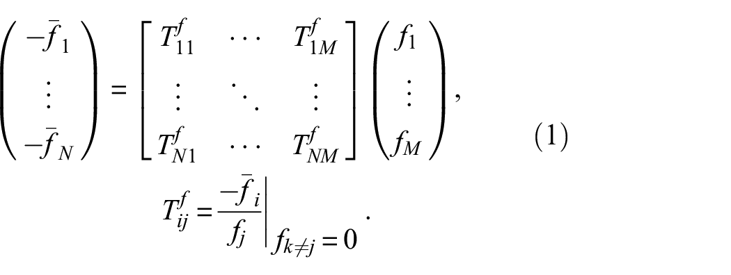
Note that the excitation and blocking force DoFs belong to different sets of measurement positions (
The response transmissibility
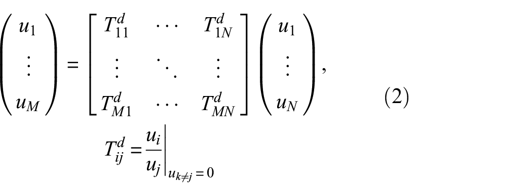
where again, the two response DoFs belong to different sets (
From the above it is clear that there exists a symmetry between the force and response transmissibility. Defined in terms of a blocking force, implicit to the force transmissibility are a set of rigid constraints. Similarly, by definition the response transmissibility requires the rigid constraint of all DoFs
The invariant nature of the transmissibility arises due to the blocking constraints present in the above definitions. If these blocking constraints are applied to the DoFs that separate a sub-structure from the remainder of its assembly, the dynamics of neighbouring sub-structures are effectively removed, and so they become invariant sub-structural properties. It is this invariance that enables, in theory, transmissibility-based metrics to localise damage.
Force transmissibility
We begin by considering the coupled AB assembly in Figure 1(a), though what follows may be generalised to more complex arrangements of sub-structures. Two sets of DoFs are considered; the remote set a, located internal to sub-structure A, and the interface set c. According to the equivalent field theorem,6,8 the response field along the interface c generated by an external force

where

Like Equation (1), Equation (4) relates the applied force
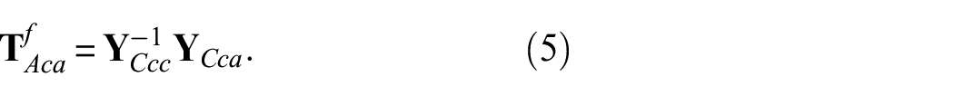
It is significant that the above definition of force transmissibility is based entirely on coupled assembly receptances. The force transmissibility
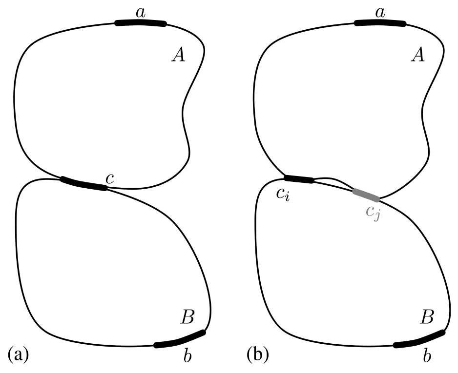
Interface representations of coupled structures: (a) single complete interface and (b) interface with known
Response transmissibility
Turning attention towards the response transmissibility, we consider the application of an external force at the interface

and

Rearranging Equation (6) to determine

where,

At first sight it is not obvious that the response transmissibility is also a sub-structural invariant. This is made clearer by considering the nature of the external force
Inspection of Equations (5) and (9) reveals that the force and response transmissibility are related. Here, as we have reversed the direction of the response transmissibility (it goes from c to a, rather than a to c like the force transmissibility), we have that,
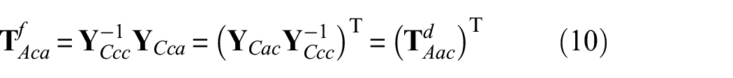
That is, the force transmissibility is equal to the transposed response transmissibility, both of which are invariant sub-structural properties. Note that in Lage et al. 9 and Meggitt and Moorhouse 4 the direction of the response transmissibility is not reversed, and so their relations include an inverse.
Note that by considering an additional set of internal DoFs b located on sub-structure B, the force or response transmissibility
In the above, both force and response transmissibilities are defined in terms of coupled assembly receptances (or more generally, structural frequency response functions (FRFs)). Whilst these FRFs are readily measurable quantities, requiring a known input force and measured response (most often an acceleration), in the context of SHM their measurement can be impractical as it requires human intervention to measure
Output-only transmissibility
Suppose sub-structure A is installed within an active assembly, that is, an assembly containing one or more vibration generating mechanisms. In this case it is possible to determine the transmissibility based on measurements of the operational response only. A key requirement of the above is that the vibration generating mechanisms do not reside within the target sub-structure, as the ‘excitation’ DoFs (taken here to be those of the interface c) must be known and instrumented.
To extend the definition of transmissibility to output-only quantities it is sufficient to consider N linearly independent operational states of the assembly AB. From the perspective of sub-structure A, each operational state can be represented by an external force

and

and Equation (8) as,

where

Similarly, using Equation (10) we can define the force transmissibility matrix as,
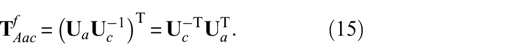
Equations (14) and (15) provide output-only definitions of the sub-structure transmissibilities
The transmissibilities obtained as per Equations (5), (9), (14) or (15) are often termed ‘global’ or ‘generalised’ transmissibilities. In contrast, the transmissibilities used most often in SHM are termed ‘local’ and are defined as the scalar ratio of responses,
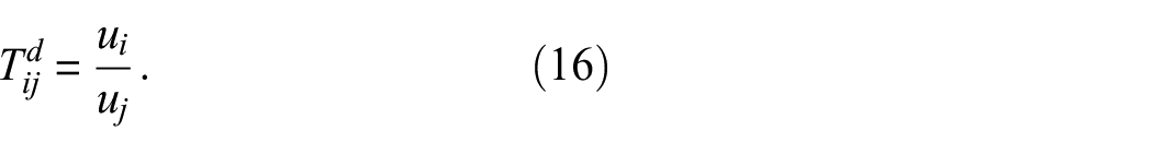
Note that this local transmissibility does not benefit from the rigid constraints present in Equation (2). Consequently, it does not provide an invariant sub-structural property. For this reason, local transmissibilities are not suitable for damage localisation.
Transmissibility-based damage metrics
In the above, it was shown that the transmissibility, when defined between a set of internal and interface DoFs, is indeed a sub-structural invariant. Furthermore, being a product of receptance functions, the transmissibility (force or response) is also sensitive to changes in the mass, stiffness or damping distribution of a structure. 12 In combination, these invariance and sensitivity properties enable the localisation of damage using transmissibility functions; the transmissibility of a sub-structure is only changed if damage occurs within that sub-structure, damage located outside that sub-structure will have no effect on its transmissibility. To the authors’ knowledge, this is the first definitive and general explanation as to why transmissibilities are able to localise damage.
Since their first use in the context of SHM,
13
various transmissibility-based metrics have been proposed to quantify the level of damage present in a structure or sub-structure, including difference-based,3,12,14–18 correlation-based19–21 and coherence-based
22
formulations. Irrespective of their formulation, the general idea is that the corresponding damage metric describes the similarity between a baseline (undamaged) transmissibility
Completeness
In our treatment of transmissibility we considered sub-structure A, whose interface was represented completely by the DoF set c. Owing to its implicit constraints, the transmissibility
Now suppose we consider the coupled AB assembly depicted in Figure 1(b), where the interface DoFs
If the intention is to use a standard transmissibility-based metric to identify or locate damage within an assembly, complete interface representations are required, else damage may falsely be attributed to the wrong sub-structure.
Quantifying completeness
Experimentally, an interface representation describes the number, and orientation, of response sensors used to instrument an interface. Completeness describes the ability of the installed sensor array to capture the full range of dynamics, or DoFs, at the interface. The DoFs that are physically present at an interface form two subsets; those that are known and measurable, and those that are unknown, or known but cannot be measured (e.g. due to poor access, or limited instrumentation). It is the presence of this latter subset that gives rise to incompleteness.
The notion of interface completeness was first introduced by Meggitt and Moorhouse 5 in the context of vibration source characterisation. It was shown that by neglecting a subset of interface DoFs, a bias error (or model uncertainty) is introduced that renders the source characterisation structurally dependent (as opposed to invariant). To quantify the severity of incompleteness, they considered mathematically blocking the known (measurable) interface DoFs, and observing the response obtained downstream of the interface when an upstream excitation is applied; in the presence of a complete interface representation, the interface is completely blocked and the observed response is zero; in the presence of an incomplete interface, some response will be observed due to propagation through the unconstrained (unknown) DoFs.
It was shown that the blocking ability of an interface representation can be assessed through the comparison of two receptance matrices that traverse the interface. With reference to Figure 1(b), the first is a directly measured receptance
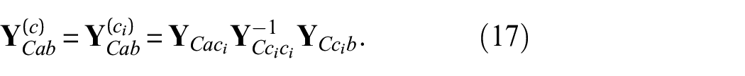
Hence, to quantify completeness, it is sufficient to assess the similarity of the direct and reconstructed receptances above. To this end, Meggitt and Moorhouse adopted a correlation-based measure of similarity and proposed the so-called Interface Completeness Criterion (ICC),

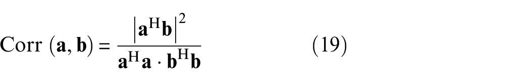
where
An alternative measure of similarity has also been proposed based on a coherence style formulation, 24

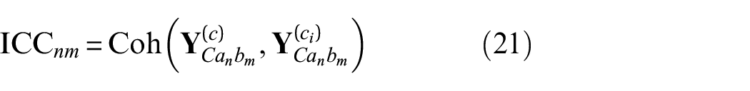
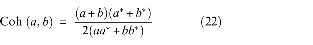
where
In the presence of a complete interface representation
To obtain the ICC, the receptances
Importantly, the ICC is a frequency dependent quantity; the contribution of each interface DoF varies with frequency depending on the modal characteristics of the structure. At certain frequencies the interface may be represented adequately using only a small subset of the DoFs present. At others, a greater number, or a different subset, may be required. Given an interface representation, the ICC indicates over what frequency range(s) the interface appears complete, and over which results should not be relied upon.
Numerical study: connected plates
In this section we investigate the influence of interface completeness on the localisation and quantification of damage for a simulated example. The case considered is illustrated in Figure 2.

Diagram of coupled plate simulation; two plates (A and B) coupled along a continuous interface. Markers: ▴– remote A DoFs, – is a fixed interface DoF used for all levels of discretisation),  – location of added mass/damage.
Two plates (A and B) are coupled along a continuous line. Damage is simulated in plate A by adding a localised mass (approx 10% of total plate mass). Transmissibilities are obtained between a discretised representation of the separating interface c and a set of remote DoFs a and b, located respectively in sub-structures A and B. The level of interface discretisation is varied and the transmissibilities obtained from the baseline,
where
The coupled plate is simulated using a modal summation approach with a simply supported boundary. Each marker shown in Figure 2 represents three DoFs, a vertical translation
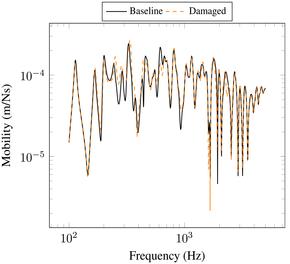
Example transfer mobilities
Shown in Figure 4(a) are the correlation-based ICCs obtained by increasing the level of discretisation through 1, 3, 5, 9 and 15 points (each with three DoFs). In Figure 4(b) are the resulting transmissibilities between a fixed interface point (red marker in Figure 2) and a remote a DoF. It is clear that as the number of points is increased, the completeness of the interface does so also. It is seen that the transmissibility obtained also depends strongly on the level of interface completeness.
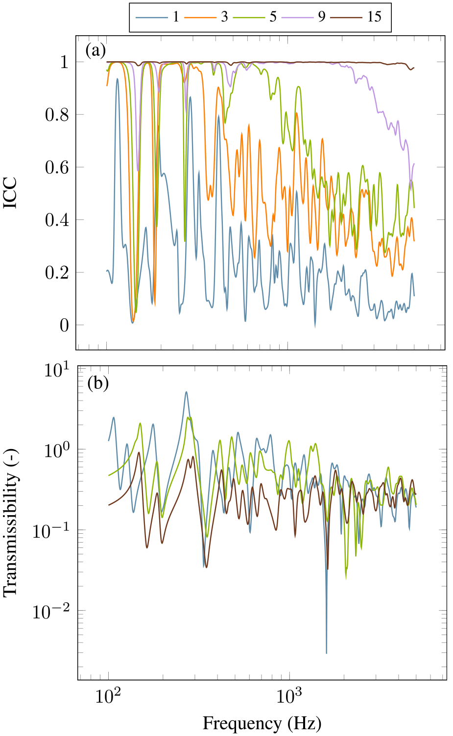
Interface completeness (a) and transmissibility (b) as a function of frequency and number of interface DoFs employed. For clarity, interface representations 3 and 9 have been omitted from (b).
Shown in Figure 5 are the ICCs obtained for the full 15 point discretisation, with and without the rotational DoFs included. In contrast to Figure 4(a) which shows a gradual increase in the frequency range that is approx. complete, neglecting rotational DoFs leads to a reduced level of completeness across the entire frequency range.
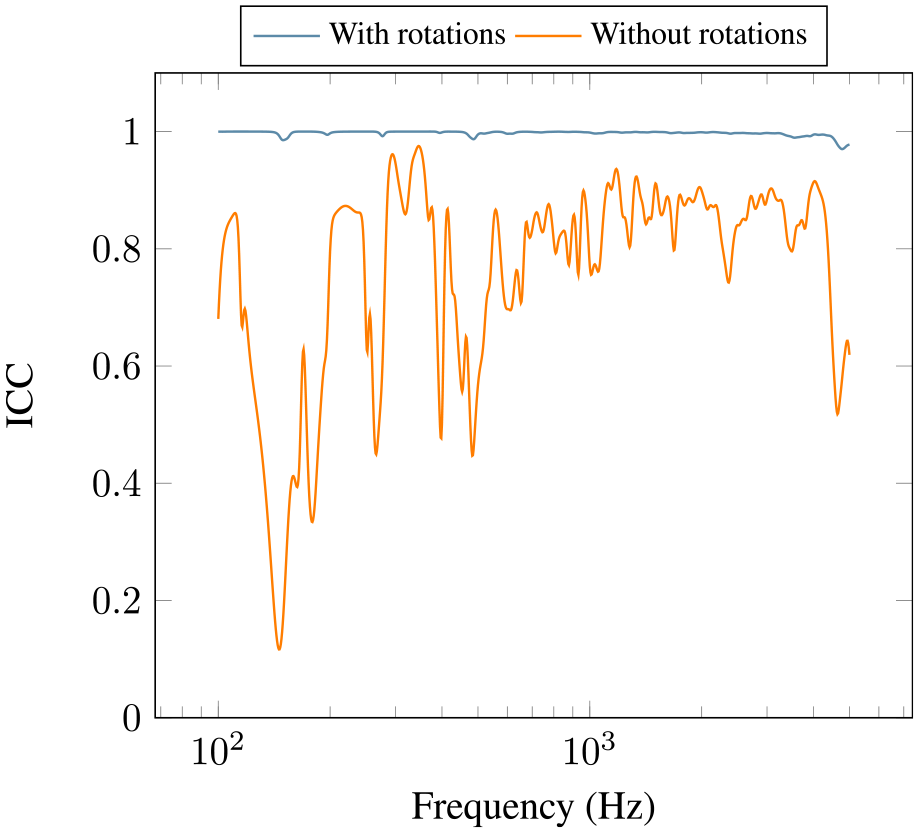
Interface completeness with 15 points, with and without rotations.
To illustrate the importance of interface completeness from a damage localisation/quantification standpoint, we consider this latter case (15 points with/without rotations) and compute the transmissibilities of sub-structures A and B for the baseline and damaged cases. For the complete interface (i.e. with rotations) these results are shown in Figure 6. Figure 6(a) shows that the transmissibility of sub-structure A is clearly effected by the damage located in A. Figure 6(b) shows that the transmissibility of sub-structure B is completely unaffected by the damage in A (note that due to the finite discretisation of the interface, some very small deviations are still seen).
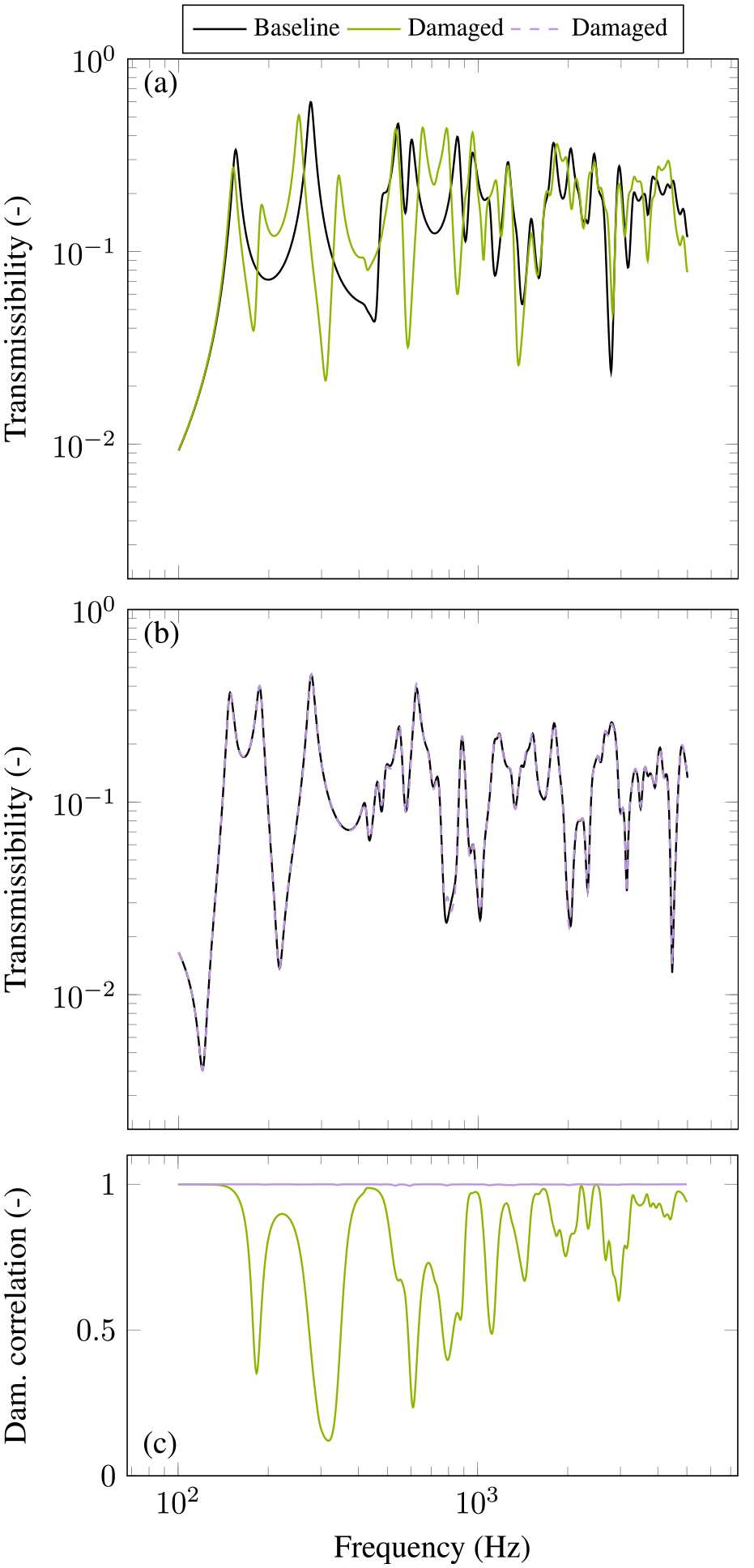
Example transmissibilities of component A (a) and B (b) for baseline and damaged systems with complete interface representation. Also shown in (c) is the damage correlation metric obtained using all transmissibilities. Single value damage metric (see Equation (23)):
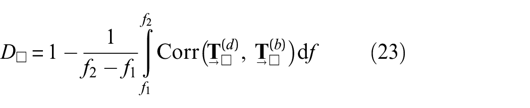
Recalling that the sub-structure transmissibilities are in fact matrices, a correlation-based comparison can be made between the baseline and damaged cases for A and B,

This result is shown in Figure 6(c). Sub-structure B, being unaffected by the damage, is near perfectly correlated with the undamaged case, whilst sub-structure A is not. Taking a shifted frequency average (as per Equation (23)) of this correlation yields the following single value damage metrics (with
Shown in Figure 7 are an equivalent set of results (as in Figure 6), though obtained from an incomplete interface representation, where rotational interface DoFs have been omitted. As before, the transmissibility of sub-structure A has been effected by the damage, but in this case so has that of sub-structure B. By neglecting the rotational DoFs at the interface, damage in sub-structure A is appearing also as damage in sub-structure B. The results of the correlation-based comparison illustrate this result more generally across the entire transmissibility matrix. The single value damage metrics obtained from Figure 7(c) are:
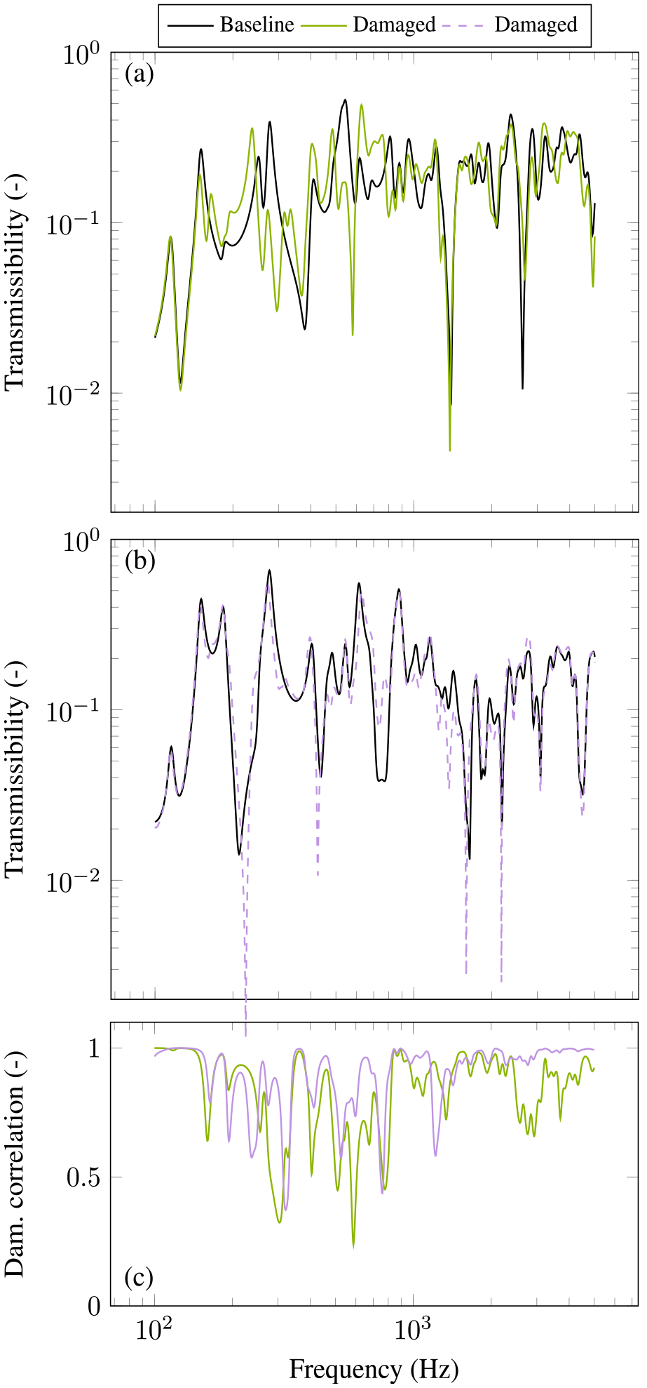
Example transmissibilities of component A (a) and B (b) for baseline and damaged systems with incomplete interface representation. Also shown in (c) is the damage correlation metric obtained using all transmissibilities. Single value damage metric (see Equation (23)):
Though the single value metrics still suggest sub-structure A to be the more likely origin of damage, this is not necessarily the case for different interface representations (i.e. levels of completeness). This fact can be illustrated by considering the damage metrics obtained as one increases the number of points used to discretise the interface (as illustrate by Figure 4). Shown in Figure 8 are the single value damage metrics obtained for sub-structures A and B for an increasing number of interface points.
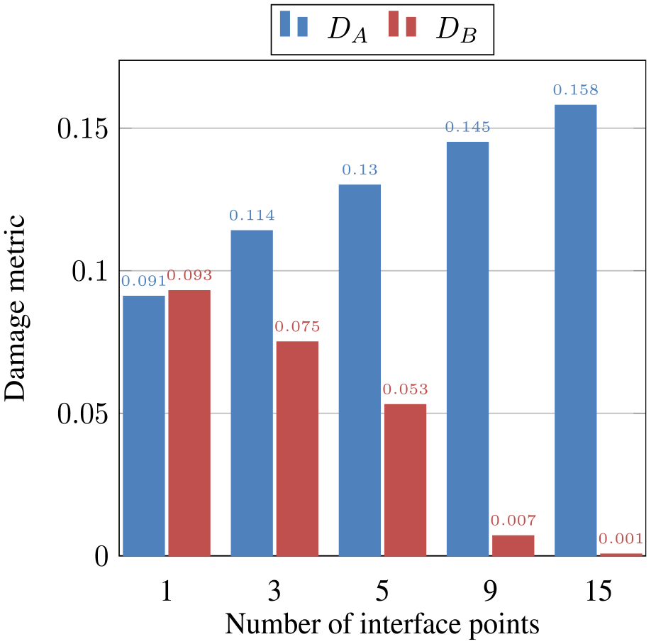
Single value damage metrics for sub-structures A and B (with damage located in A) for increasing levels of interface discretisation.
The trends observed in Figure 8 represent main the contribution of this paper. For a high level of interface completeness (15 points), transmissibilities are able to accurately locate damage, as illustrated by the clear separation between
Experimental study: connected beams
In this section we will investigate the robustness of transmissibility-based damage localisation on a more conventional point-like separating interface. The structure under study is shown in Figure 9; a beam component (A) is connected to a frame-like structure (B) composed of four beams bolted together. We consider both a rigid and resilient (i.e. vibration isolated) coupling between the two components. For each, we measure the transmissibilities
Note that the transmissibilities obtained using the
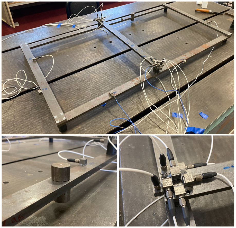
Photo of experimental structure with resilient connection (top), added mass (bottom left) and interface instrumentation (bottom right).
Shown in Figure 9 is a photo of the instrumented interface – seven uniaxial accelerometers and seven applied forces are used (per connection) to measure the coupled interface mobility matrix
Shown in Figure 10 is an example of the FD mobility in the vertical z direction at one interface connection point for the baseline and damaged case. It is clear from this result that the structure’s FRF is most affected in the high frequency regime. To give the damage localisation the best chance of success, the single value damage metric will be obtained using the frequency limits
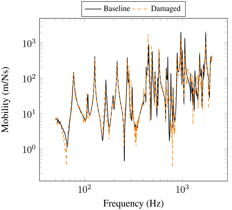
Example point mobilities
Shown in Figure 11 are the ICCs for each of the representations, over the chosen frequency range, for the rigidly coupled case. These results suggest that
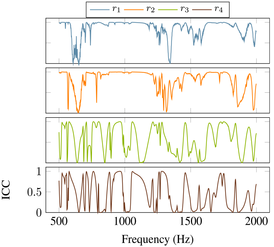
Interface completeness obtained for each representation
Shown in Figure 12 are the single value damage metrics obtained for A and B, whilst rigidly coupled, using the various interface representations described above. In all cases the damage was located in B. Before discussing the results however, it is important to note that the calculation of transmissibility requires the inversion of an interface mobility matrix
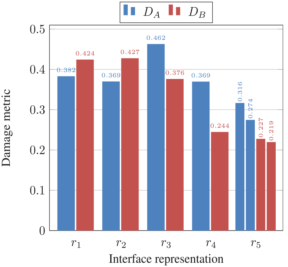
Single value damage metrics for sub-structures A and B (rigidly coupled with damage located in B) for different interface representations.
The results of Figure 12 demonstrate that for certain interface representations, specifically
Importantly, representations
Shown in Figure 13 are the ICCs for each of the representations, over the chosen frequency range, for the resiliently coupled case. These results suggest that all representations provide reasonable levels of completeness.
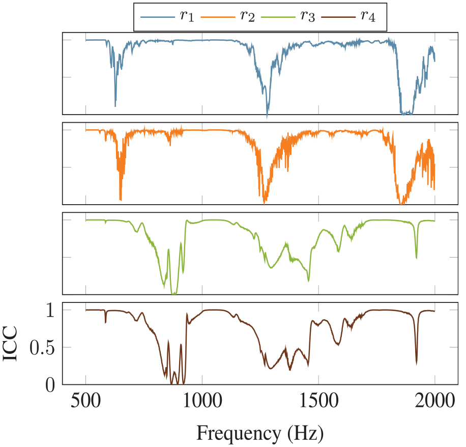
Interface completeness obtained for each representation
In fact
Shown in Figure 14 are the single value damage metrics obtained for A and B, whilst resiliently coupled, for the same interface representations as before. Note that in this case, the interface
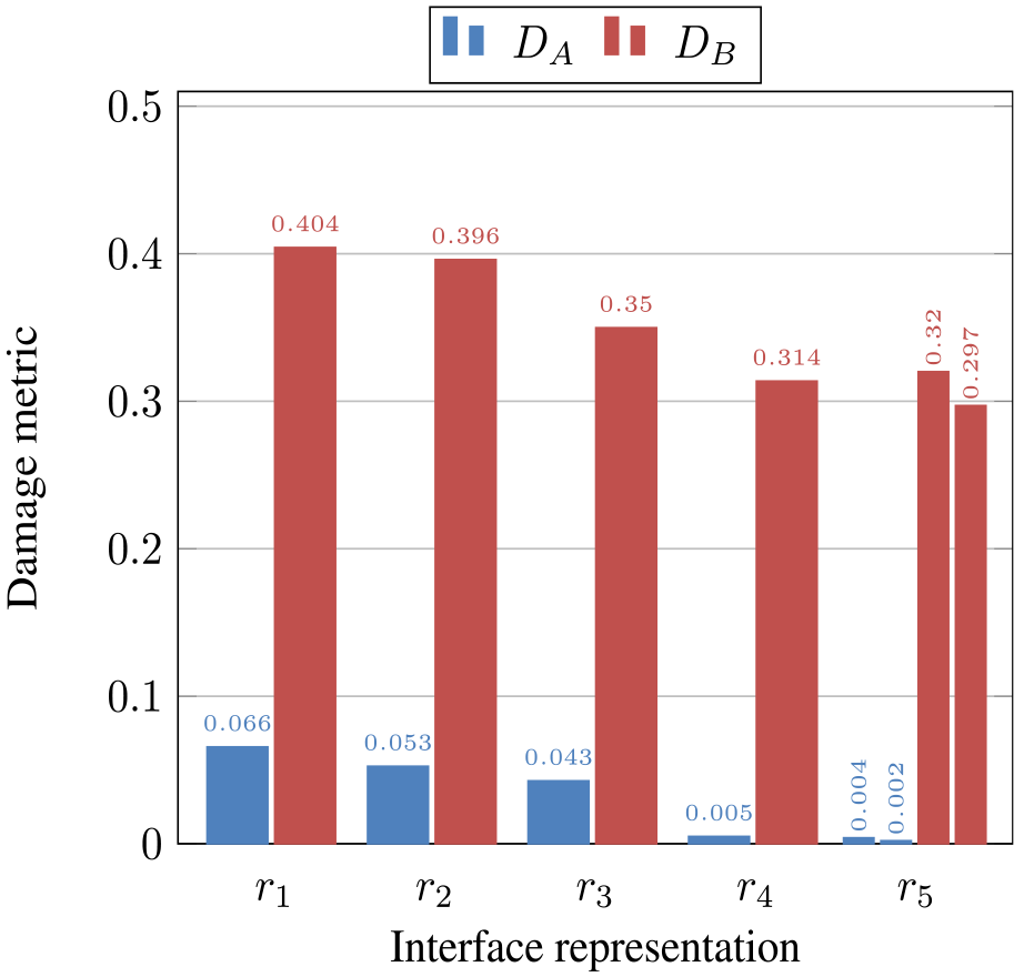
Single value damage metrics for sub-structures A and B (resiliently coupled with damage located in B) for different interface representations.
Another interesting result from Figure 14 is the general downward trend of the damage metric (for both A and B) as the number of interface DoFs is reduced. Again, this is likely due to the reduced influence of experimental error, as the matrix inversions required reduce from
Conclusion
Transmissibility functions have been used widely within the SHM community over the past two decades. Compared to conventional FRFs (e.g. mobility), they are a) available using output-only methods, and b) have been shown to provide better localisation capabilities, though no definitive explanation for this latter feature has been offered. In the present paper we elucidate the origins of this capability; the blocking constraints present in the definition of both force and response transmissibility. Indeed, the (generalised) transmissibility, when defined between a complete set of interface DoFs and a set of remote points, becomes a sub-structural invariant; it is influenced only by damage located within that sub-structure. This unique property of sub-structural invariance is, however, reliant on the use of a complete interface representation, that is, a sufficient number of DoFs should be captured at the component’s separating interface. How many, and which DoFs will depend on the structure under study.
It was shown, through a series of numerical and experimental studies, that the completeness of an interface representation is directly correlated to the localisation accuracy of transmissibility-based damage metrics. It was further shown, that for the studies considered, incomplete representations can lead to damage being falsely attributed to the wrong sub-structure.
From these results we conclude that transmissibility-based metrics should not be relied upon, without sufficient understanding of the interface representation and its level of completeness. Furthermore, the present study raises the question whether knowledge of the interface completeness can be used to develop more robust transmissibility-based metrics that avoid the need for excessive instrumentation.
Footnotes
Appendix
Acknowledgements
The authors would like to acknowledge the support of DSTL.
Declaration of conflicting interests
The author(s) declared no potential conflicts of interest with respect to the research, authorship, and/or publication of this article.
Funding
The author(s) received no financial support for the research, authorship, and/or publication of this article.