
Abstract
This paper proposes a framework for obstacle-avoiding autonomous unmanned aerial vehicle (UAV) systems with a new obstacle avoidance method (OAM) and localization method for autonomous UAVs for structural health monitoring (SHM) in GPS-denied areas. There are high possibilities of obstacles in the planned trajectory of autonomous UAVs used for monitoring purposes. A traditional UAV localization method with an ultrasonic beacon is limited to the scope of the monitoring and vulnerable to both depleted battery and environmental electromagnetic fields. To overcome these critical problems, a deep learning-based OAM with the integration of You Only Look Once version 3 (YOLOv3) and a fiducial marker-based UAV localization method are proposed. These new obstacle avoidance and localization methods are integrated with a real-time damage segmentation method as an autonomous UAV system for SHM. In indoor testing and outdoor tests in a large parking structure, the proposed methods showed superior performances in obstacle avoidance and UAV localization compared to traditional approaches.
Keywords
Introduction
Deep learning-based structural damage detection is a hot topic in the construction and structural health monitoring (SHM) field. Cha et al.1,2 proposed a new deep convolutional neural network (DCNN) for structural damage detection using vision sensors. It has received enormous interest worldwide, with numerous studies following.3–5 To quantify detected damage, damage segmentation methods using deep learning have been extensively investigated by many researchers. For example, U-Net 6 and its transformed algorithm have been applied.7–9 Choi and Cha 10 suggested a fast, efficient deep semantic network for crack segmentation in complex scenes by using an atrous pyramid pooling network and “DenSep” modules. Saleem et al. 11 applied Mask R-CNN 12 for crack segmentation. They tested image data of a real bridge structure collected by unmanned aerial vehicles (UAVs). Yu et al. 13 developed a DCNN and enhanced chicken swarm algorithm to improve the accuracy and computational cost for the automated detection of concrete cracks. Abdeljaber et al. 14 developed a novel, fast, and accurate real-time structural damage detection system using one-dimensional convolutional neural networks (1D CNNs) that automatically extract damage-sensitive features from raw acceleration signals. In another study, a new approach for detecting compressive stress and load-induced damage in concrete structures using a DCNN integrated with electromechanical admittance (EMA) was proposed. 15 Two-dimensional convolutional neural network (2D CNN) for rapid damage quantification in concrete structures using raw EMA data has also been used. 16 Potenza et al. 17 suggested color histogram-based segmentation for UAV data collected from a real bridge structure. Kang and Cha 18 developed a semantic transformer representation network (STRNet) to segment cracks at the pixel level in a complex background scene. It shows state-of-the-art performance in terms of accuracy and processing speed. The reported mean intersection over union (mIoU) is 92.6%, with 49.2 frames per second (FPS) and an image size of 1024 × 512 × 3. However, the method has not yet been implemented with UAV images but rather with images collected from fixed-installed cameras. Bao and Li 19 proposed that machine learning can be used to analyze monitoring data to discover and model the performance and conditions of a structure, thereby creating a “machine learning paradigm” for SHM. 19 In another study, a fusion CNN architecture was developed for crack identification in the steel box girders of bridges based on real-world images containing complicated disturbance information. 20
UAVs are attractive for various applications, including SHM, since they can overcome accessibility difficulties without heavy machinery, reduce overall costs, and increase the frequency of inspections.21,22 For example, McGuire et al. 22 tested a commercial UAV for bridge and tower inspections. Benz et al. 23 conducted a bridge inspection using a UAV and suggested a new crack segmentation algorithm based on a pretrained CNN. However, all these applications are limited to manual flights. Manually flying a UAV requires a skillful pilot and thus is costly, nor is it feasible for mass application to numerous bridge structures.
Recently, Kang and Cha 24 and Ali et al. 25 developed an autonomous UAV flight method for structural damage detection and localization in areas where a global position system (GPS) signal is not available. Generally, GPS signals are weak or unavailable beneath a bridge deck or indoors. To replace the GPS signal, an ultrasonic beacon system (USB) was used to generate a three-dimensional (3D) pseudo map. Additionally, a deep CNN 25 was used to detect cracks on concrete floors. Kang and Cha 24 study was the first trial of an autonomous UAV system for SHM. However, USB signals are vulnerable to various magnetic fields due to transmission towers or electric vehicles and machinery. Further, the method did not have a function to avoid obstacles in the planned trajectory of autonomous navigation.
Obstacles such as beams or pillars can present difficulties for this UAV-based SHM. There are various solutions to avoid obstacles. For example, González et al. 26 implemented a one-degree laser distance sensor in the frontal direction of a UAV. In their research, the UAV detected a wall by using the distance sensor, but this 1D sensor missed small obstacles or obstacles that are not in field of the (1D) sensor. Song et al. 27 implemented a 3D light detection and ranging (LIDAR)-based simultaneous localization and mapping for obstacle avoidance and 3D mapping for bridge inspection. 3D mapping using 3D LIDAR is promising for future SHM, but 3D LIDAR is much more expensive and much heavier than an RGB camera. Therefore, it may require very large payload UAVs, which are not appropriate for navigating inter-story or narrow areas, such as between pillars or bridge piers.
Although in the SHM field, research on obstacle avoidance methods (OAMs) for UAVs has not yet started, obstacle avoidance for UAVs is a popular topic in robotics. For example, Mori and Scherer 28 suggested one of the first attempts for a single camera-based obstacle avoidance algorithm for a UAV. The algorithm detects the obstacle by using speeded-up robust features 29 and avoids it. More recently, Smolyanskiy et al. 30 and Loquercio 31 suggested deep learning-based OAMs by supervised training of a CNN to predict steering angle and collision probability in a road scene image for UAV control, but this approach is not guaranteed to respond to unexpected environmental features because the algorithm is limited to the variety of training data. Afterward, depth estimation from a single camera was developed for obstacle distance estimation.32,33 However, none of these approaches have been implemented in the SHM field.
In this paper, to overcome the limitations of the USB and realize an obstacle avoidance autonomous UAV system for SHM in a GPS-denied environment, a new OAM based on fiducial markers is proposed. Fiducial markers do not need electric batteries to operate, and small markers (4 cm × 4 cm) can be attached at UAV waypoints to establish a navigation trajectory. The developed autonomous UAV system was tested in indoor and outdoor environments, and the collected videos were analyzed by STRNet to segment cracks at the pixel level. The paper is organized into three additional sections. Section “Methodology” describes the proposed OAM with a fiducial marker-based autonomous navigation method and provides a brief explanation of STRNet. In Section “Case studies,” the experimental tests and performances of the OAM and STRNet are discussed. Section “Conclusion and future direction” presents the conclusion and limitations and suggests future improvements.
Methodology
An obstacle-avoiding autonomous UAV navigation control method is proposed for civil SHM. The automated navigation method is composed of a two-level fight controller using two proportional -integral -derivative (PID) controllers and an object avoidance method to modify the planned trajectory of the UAV system when the UAV encounters obstacles, as shown in Figure 1. We propose two types of applications for the OAM, namely 3D USB-based (https://marvelmind.com/) and fiducial ArUco marker-based 34 (https://www.uco.es/investiga/grupos/ava/portfolio/aruco/.) localization techniques to realize autonomous navigation in GPS-denied areas (Figure 1).
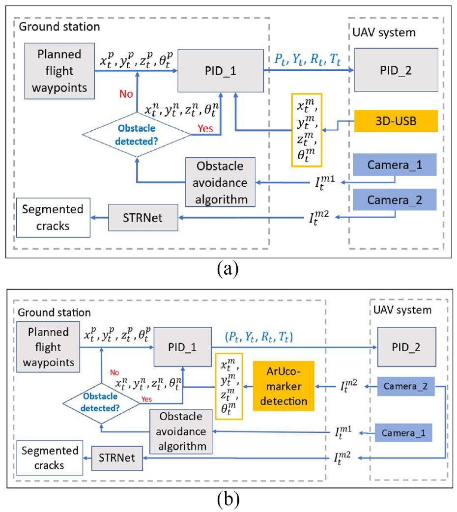
Autonomous UAV-based SHM system architecture. (a) 3D-USB-based autonomous navigation and (b) ArUco marker-based autonomous navigation.
To inspect civil infrastructure, as the first step, waypoints of the UAV navigation should be defined using either 3D USBs or ArUco markers. The planned waypoints are a series of 3D coordinates composed of
For the first approach (Figure 1(a)), a 3D pseudo map is constructed using four stationary beacons in the area the UAV will navigate. The measured coordinates
For the second approach (Figure 1(b)) of localization, ArUco markers are used to create a 3D-pseudo map in the area the UAV will navigate. This method detects markers in the incoming image frame
Obstacle avoidance method
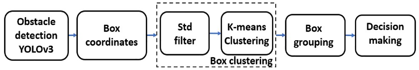
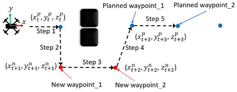
The overall procedure of the obstacle avoidance algorithm that we propose in this paper (as shown in Figure 2) is as follows: (1) obstacles are detected by You Only Look Once version 3 (YOLOv3)
35
using the input image,
Steps in obstacle avoidance.
In this study, the UAV can avoid the obstacle by moving either of right or left direction. The decision is made based on the location of the center point of the clustered bounding box compared to the center point of the entire image,
Detection of obstacle using YOLOv3
To detect any number of obstacles, YOLOv3, which is composed of an encoder and decoder, is used as an example network. It can be replaced by any recent version of YOLO series. DarkNet53 36 is used as the encoder. The decoder of the YOLOv3 consists of three detection layers (expressed as greenish boxes in Figure 3) and upsampling layers having different scales (expressed as blueish boxes in Figure 3).
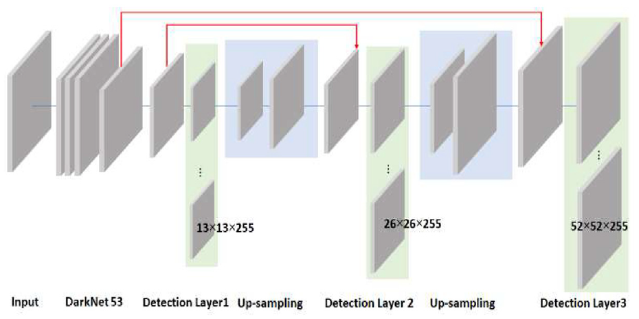
YOLOv3 architecture.
The input size of YOLOv3 is resized to 416 × 416 × 3 from the original image size of 540 × 480 × 3. DarkNet 53 is used to extract the feature maps having sizes of 13 × 13 × 255, 26 × 26 × 255, 52 × 52 × 255 in “Detection Layer 1,”“Detection Layer 2,” and “Detection Layer 3,” respectively, as shown in Figure 3. The main purpose of using these multiple feature maps by upsampling is to consider different levels of features to improve the object (obstacle) detection performance. The depth of the feature map is evenly 255, composed of three anchors (i.e., anchor 1, anchor 2, and anchor 3). Each anchor dimension is 1 × 1 × 85 to represent bounding box coordinates
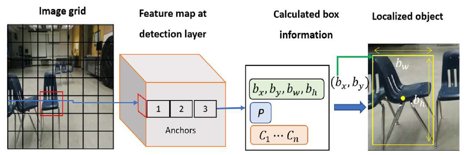
Obstacle detection process.
As an example, multiple chairs are used as obstacles. The bounding box coordinates, object confidence, and class scores are multiplied by the sigmoid function, and the bounding box width,
Obstacle clustering
YOLOv3 provides N number of bounding boxes depending on the number of obstacles in the input image, where
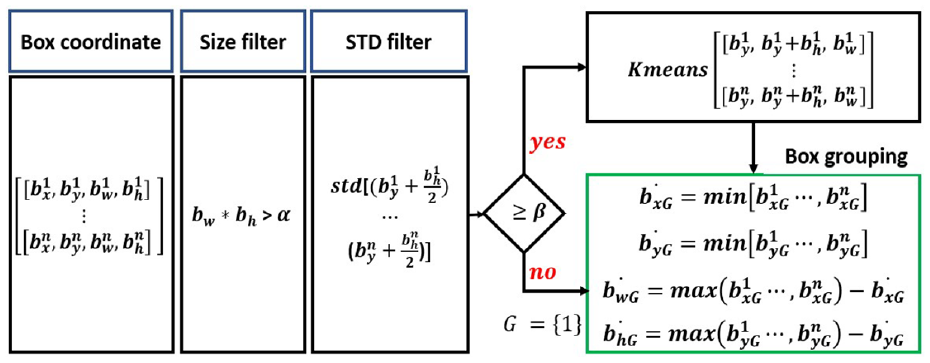
Box clustering algorithm.
As the first step of the method, a “Size filter” (i.e.,
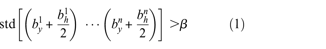
where
When the calculated STD value is greater than β, K-means clustering is applied to form multiple groups. This K-means clustering generates multiple groups to the bounding boxes that are provided by the YOLOv3, as shown in Figure 6.
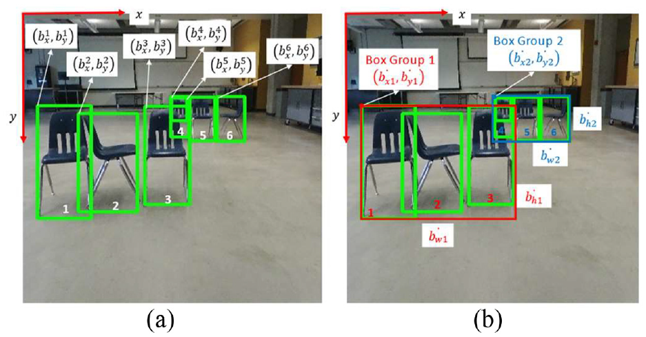
Obstacle detection and obstacle clustering: (a) original YOLOv3 result and (b) obstacle clustering result.
The output from K-means is
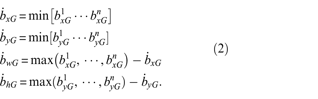
Using the calculated values
Estimation of distance of UAV from obstacle
Now, we should calculate the distance between the UAV camera and the obstacle to figure out how to avoid it. For estimation of the distance of the UAV from the obstacle, it is assumed that width W and height H of the obstacle are known because YOLOv3 is used to predict the bounding box and class of obstacle. To increase the robustness of our algorithm and adapt it to different types of obstacles, we logged the heights and widths of various obstacles that may be present in the SHM environment. To obtain the distance of the object from the camera, the pinhole camera model is used, as shown in Figure 7.
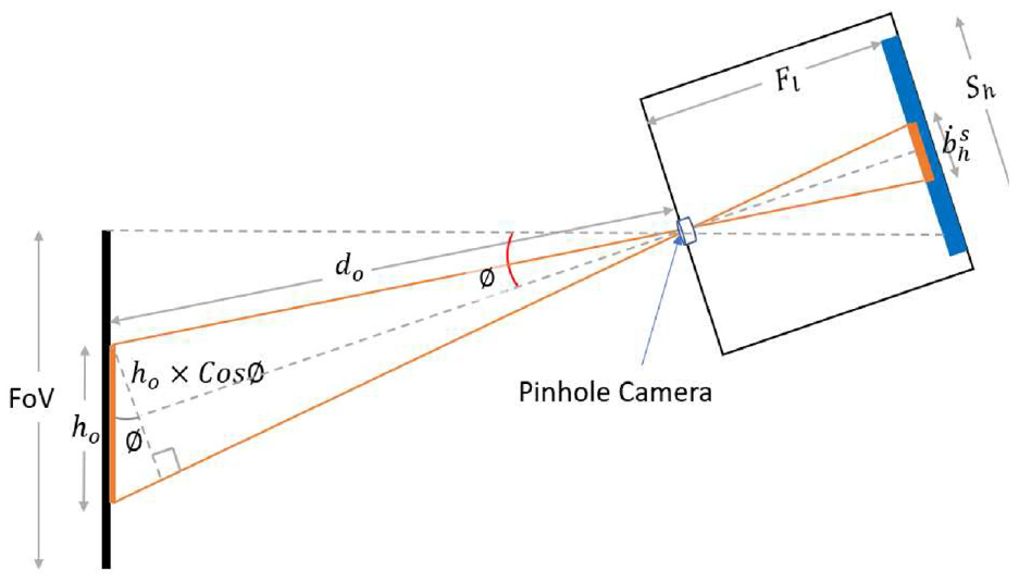
Schematic view of a pinhole camera model.
In the first step of distance calculation, the obstacle is detected in image
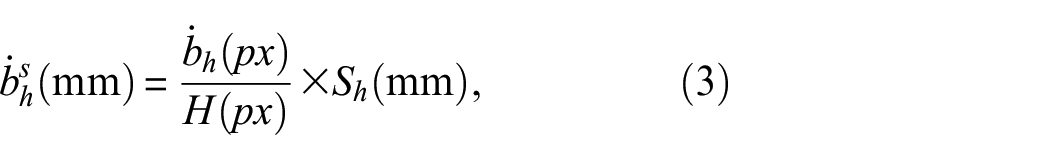
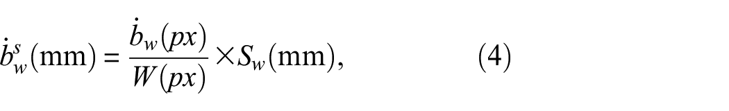
where
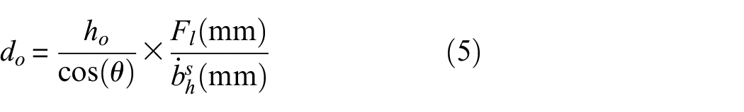
where
Generating new waypoint
When obstacles are detected in Step 1 in Figure 8, the proposed OAM has to figure out a new waypoint based on the distance between the UAV and the obstacles. In this case, only the first group of obstacles closer to the UAV (shown in Figure 6(b) as a red rectangle) is considered. When the calculated distance
Generating new waypoints with OAM.
The next step is to determine a new waypoint to avoid obstacles. To do this, the center
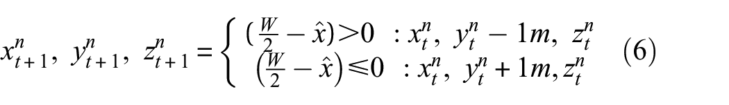
If
At the new waypoint
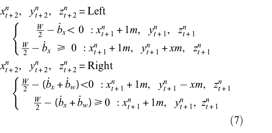
ArUco marker detection
To navigate a GPS-denied area autonomously, a USB was implemented by Kang and Cha. 24 However, the USB was vulnerable to magnetic interference; therefore, sometimes, it did not provide reliable signals and resulted in poor localization of the UAV, which is explained in later sections. To overcome this limitation of the USB, we introduce an ArUco marker-based UAV localization method.34,39 An ArUco marker is a square-shaped marker, as shown in Figure 9, with a black and white square patch containing a unique barcode. Multiple numbers of installed ArUco makers establish a 3D pseudo map to replace GPS signals, and each ArUco marker’s 3D coordinates based on this 3D pseudo map are saved in a marker library in the ground station. Then, we can set the starting waypoint of the UAV based on this 3D map. Because each marker has a unique binary barcode, the barcode number is used to find its location information in the library; therefore, we must read the barcode using image processing.
Schematic block diagram of ArUco marker detection process: (a) convert image to grayscale, (b) local adaptive thresholding and contour filtering, (c) rectangular image patch selection, and (d) assign the binary value 1 or 0.
The first step is to detect this barcode from
The ArUco marker detection method is robust against environmental distractions by using unique corner detection and increasing the number of bits in the marker. Using markers with a higher number of bits ensures that the pattern is complicated, so that it does not occur in the monitoring environment and improves robustness. Additionally, false detections can be filtered by using a predefined dictionary of markers. If a fake marker is detected and it exists in the dictionary, it will not affect the UAV’s position as it corrects its position based on the next true marker detected.
UAV localization
For autonomous flight using only ArUco markers, UAV spatial coordinates and pose
Attached ArUco markers (white circle) in the ceiling of the reinforced concrete structure.
Each marker in the pseudo map has its own local coordinate system
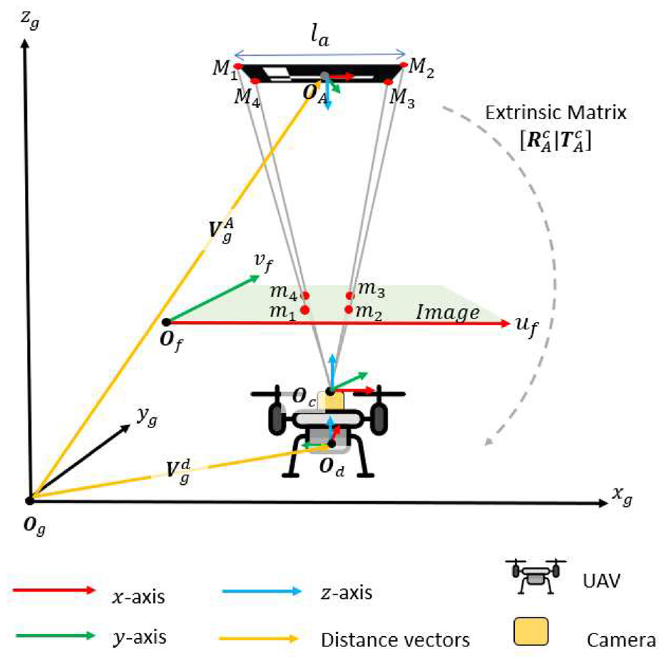
UAV localization in the pseudo map using ArUco markers.
In the first step of localization, the marker’s unique barcode information is decrypted from the incoming frame
Next, to find the location and pose of the camera using ArUco markers, we adopted Burger’s pose of the camera estimation method
43
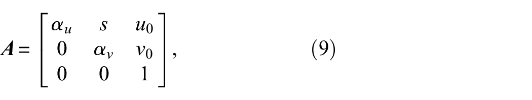
to this UAV camera pose estimation problem. It is assumed that the markers’ dimensions
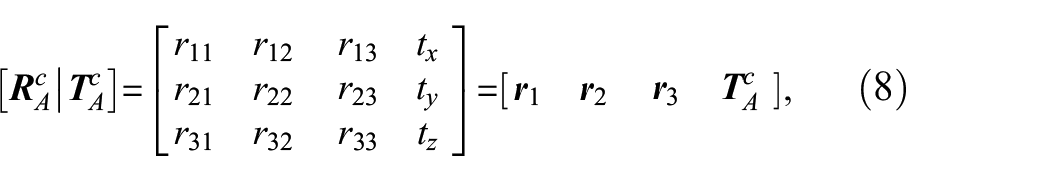
where
where
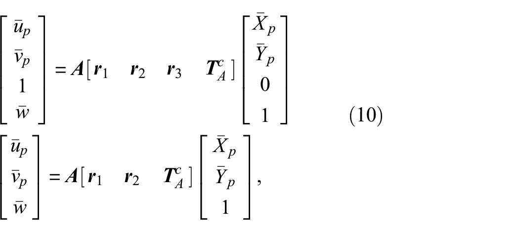
where
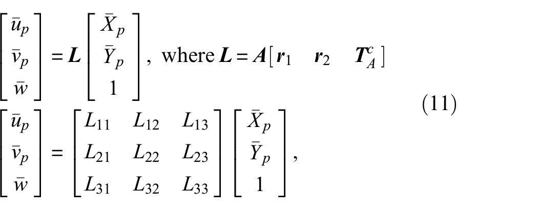
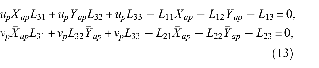
where
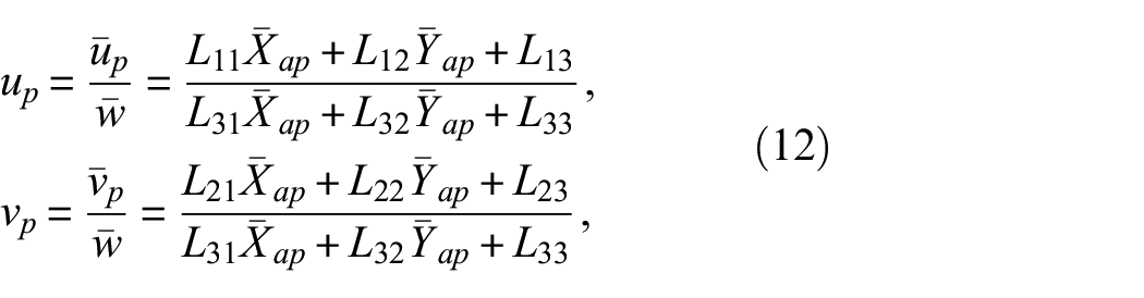
which can be rearranged to Equation (13):
which can be written in matrix form as shown in Equation (14):
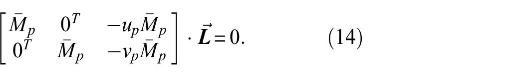
Here,
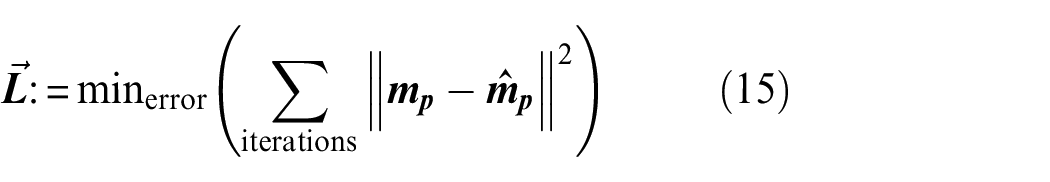
where


where
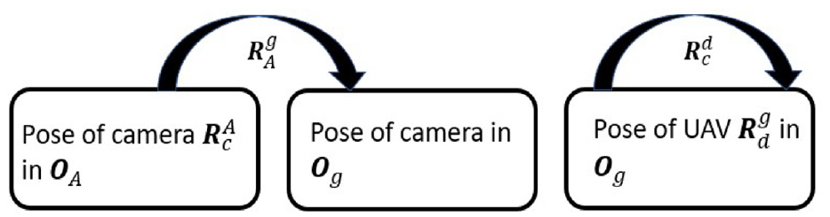
Rotation transformations to find pose of UAV.
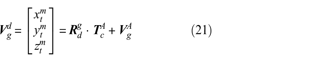
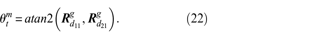
The series of transformations can be shown in Equation (20):

where
where
Here, for
Crack damage segmentation using STRNet
For a damage detection task, we recently used an existing algorithm called STRNet,
18
which is an advanced crack segmentation algorithm. STRNet is a deep learning network for crack segmentation in a complex background for real-time processing (i.e., 49 FPS for a relatively large size input image (1024 × 512)) using a self-attention-based decoder, as shown in Figure 13. The input image
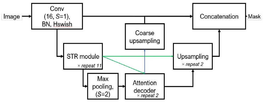
STRNet architecture.
STR module
CNNs use many convolution layers to extract an object-focused feature map. The computational cost of a convolutional operator is usually dependent on kernel size (k), input channel (C), input width (W), input height (H), and output channel (O). The computational costs of a traditional (T) convolution, depthwise (DW) convolution, PW, and their combination are calculated as


As shown in Equations (23) to (26), the cost is heavily affected by C, H, and W. To reduce computational costs, a pooling layer or convolution with two strides is usually applied. When we increase the size of the stride, W and H from Equations (23) and (26) are reduced. Therefore, proper sizes of the strides in each layer and operator are important to reduce the computational cost of a specific network, but the increase of stride may cause the loss of important features. This is a very critical problem in crack segmentation, since crack lines are thin, and specific feature loss may critically reduce the performance of the segmentation. To overcome the issue, an STR module was developed. The STR module consists of “Compress,”“Attention,” and “Restoration” modules. The base module is mainly composed of the PW and DW convolution blocks. As shown in Figure 13 Compress module applies DWs to increase stride sizes, and the compressed feature map is passed to the Attention module which includes a squeeze and excitation block (SE block). 49
In the SE block, to produce the attention map, global average pooling is applied for the input feature map, and two linear functions and all activation functions, such as rectified linear unit 50 and H-sigmoid, 51 are performed as a squeezing process. Then, the squeezed feature map is expanded by coping of the squeezed map to the input size of the SE block to apply the matrix multiplication (■). Finally, it is multiplied by the input of the SE block. The compress and restoration block (CRB) compresses the width and height of the input feature map and recovers the compressed size of the feature map to the original input feature map of the STR module by combining the reserved features using the skipped connection. The concatenation operation helps prevent a vanishing gradient and the loss of important features.
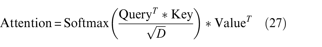
Attention decoder
After the STR encoder, we apply the attention decoder, as shown in Figure 14. The original concept of attention comes from a previous study. 52 Recently, an improved attention-based model, transformer, proposed by Vaswani et al., 53 applies multi-head attention using Key, Query, and Value. Query, Key, and Value are calculated using scaled dot-product to find the attention map and enhance the important features. This can be expressed by Equation (27)
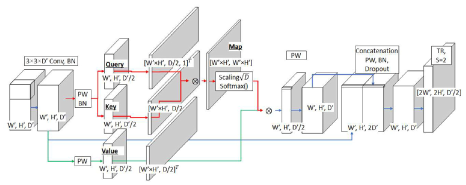
Attention decoder for STRNet.
Data generation for training of STRNet
Deep learning-based semantic segmentation methods have been actively adopted in pixel-level crack segmentation research in the last few years. However, annotating highly accurate segmentation data entails high labor costs because of labeling ground truth. For example, the annotation at the pixel level for PASCAL VOC is evaluated to be 239.7 seconds per image. 54 Annotating crack images take approximately 20–40 min. 55 To reduce the time required to prepare the dataset, we considered two options: (1) a public dataset and (2) raw images only.
Public concrete crack datasets exist.10,56–58 Although Choi and Cha 10 created a dataset using large-sized images, most other public crack datasets contain small-sized images, and the image and mask occasionally have errors. Furthermore, almost all public crack datasets have images with very simple backgrounds. For this reason, many public crack images were not selected for our training dataset, and a new dataset was developed 18 (see Table 1).
Crack datasets for training and testing (Kang and Cha, 2021).
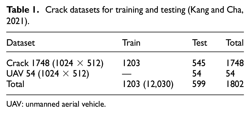
UAV: unmanned aerial vehicle.
STRNet training and evaluation
In this experiment, STRNet was trained using the data tabulated in Table 1. The Python programming language 46 with the Pytorch 1.6 deep learning library 59 was applied to implement STRNet. It was trained with four Titan XP graphics processing units (GPUs). The workstation had an Intel Core i7-6850 K central processing unit (CPU) and 128 GB memory. To train our models, the Nvidia Apex distributed data parallel training library was used to utilize the multi-GPUs. The input image size was 1024 × 512, which is randomly cropped if the image size is greater than the input size. The use of proper loss function is critical; therefore, we investigated several loss functions, such as cross-entropy loss, dice cross-entropy loss, and mIoU. Eventually, the focal Tversky loss function showed the best performance. 60 The formulation of the loss function is presented in Equation (28)
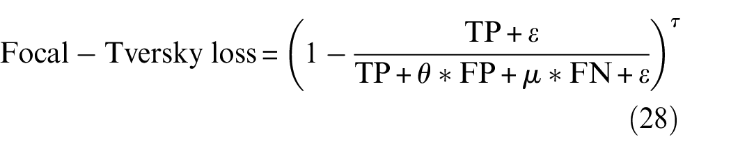
The hyperparameters
An Adam optimizer was applied as the optimizer, and the hyperparameters of
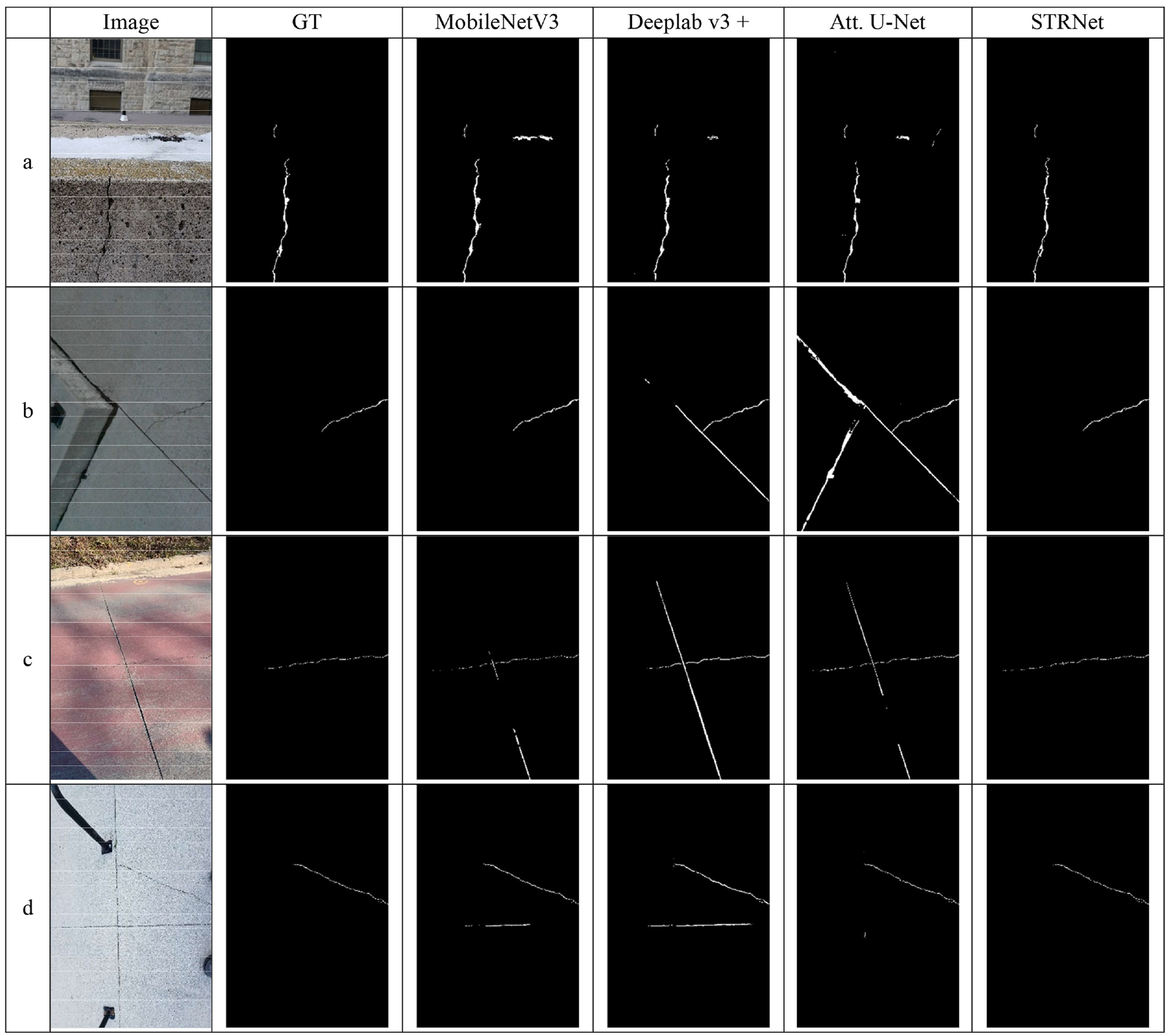
Example results of the comparative studies on complicated images: (a) concrete crack with a building in background, (b) concrete crack on pavement, (c) thin crack on concrete with grass in background and (d) crack with slab joints.
To calculate mIoU, we used Equation (29) since it can properly consider FP and FN compared to the other recall, precision, and F1 scores
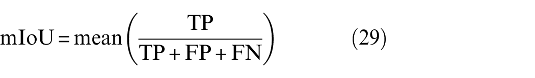
Using the dataset presented in Table 1, we conducted extensive training and testing, and the results are presented in Table 2. STRNet achieved the best
Performance comparison of different models for crack detection on UAV images and crack segmentation on ground images.

FPS: frames per second; mIoU: mean intersection over union; UAV: unmanned aerial vehicle.
The bold values are highlighting mIoU performance of networks.
MobileNetV3 included a false positive object in images a, c, and d. Deeplab v3+ showed more severe false positive detection in all the images. Attention U-Net detected expansion joints as cracks in images a, b, and c. The difficulty of the crack 1748 dataset lies in complex scenes and various shapes of crack-like objects. STRNet successfully overcame most of these challenging problems and showed very accurate segmentation results. Based on these achievements, STRNet was implemented on the images taken from the UAV camera for inspection. The results are presented in Section “Case studies.”
Case studies
Parrot Bebop 2 Power Drone 63 and Anafi 64 (https://www.parrot.com/en/about-parrot) were selected to test autonomous UAVs, as shown in Figure 16. This allows the developer to develop their own controller for autonomous navigation. A laptop computer with an Intel Core i7 2.6 GHz CPU and Nvidia Geforce (https://www.nvidia.com/en-us/) 1060 GPU communicated with the UAV through Wi-Fi-based communication. The front camera of the UAV was used for obstacle detection, and due to the limitation of the payload, a lightweight camera was chosen as the second camera for damage (crack) segmentation. As the second camera, we used the Hawkeye Firefly Micro Cam 160 model, as indicated in the red box in Figure 16. We modified the hardware of the camera to install it on the UAV. Two UAV localization methods, Marvelmind USB for indoor experiments and ArUco marker-based localization for outdoor experiments, were used, as explained in Figure 1 in Section “Methodology.” The details of experimental testing and validation for indoor and outdoor environments are explained in the following subsections “Indoor experiments” and “Outdoor experiments,” respectively.
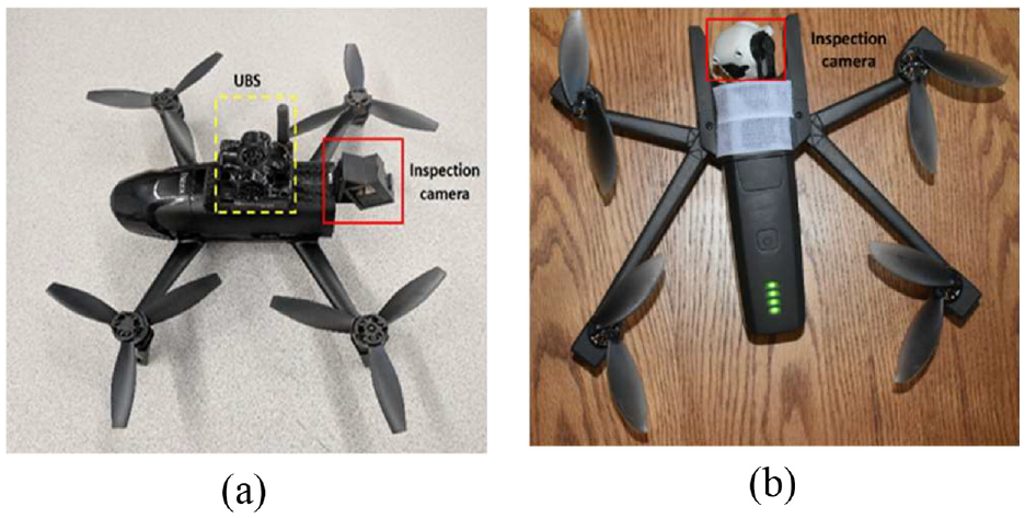
Hardware settings: (a) USB-based approach with Marvelmind beacon; inspection camera: Firefly Micro Cam 160 model, Bebop Power 2, and; (b) ArUco marker-based approach using an Anafi UAV.
Indoor experiments
The proposed OAM was initially tested in an indoor environment with a USB-based localization method. In order to investigate the performance, it was compared with existing OAMs such as the MonodepthV2 (Godard et al., 2019) 32 and AdaBins (Bhat et al., 2020) 33 approaches. Details of the OAM and STRNet experimental tests are provided below.
Obstacle avoidance
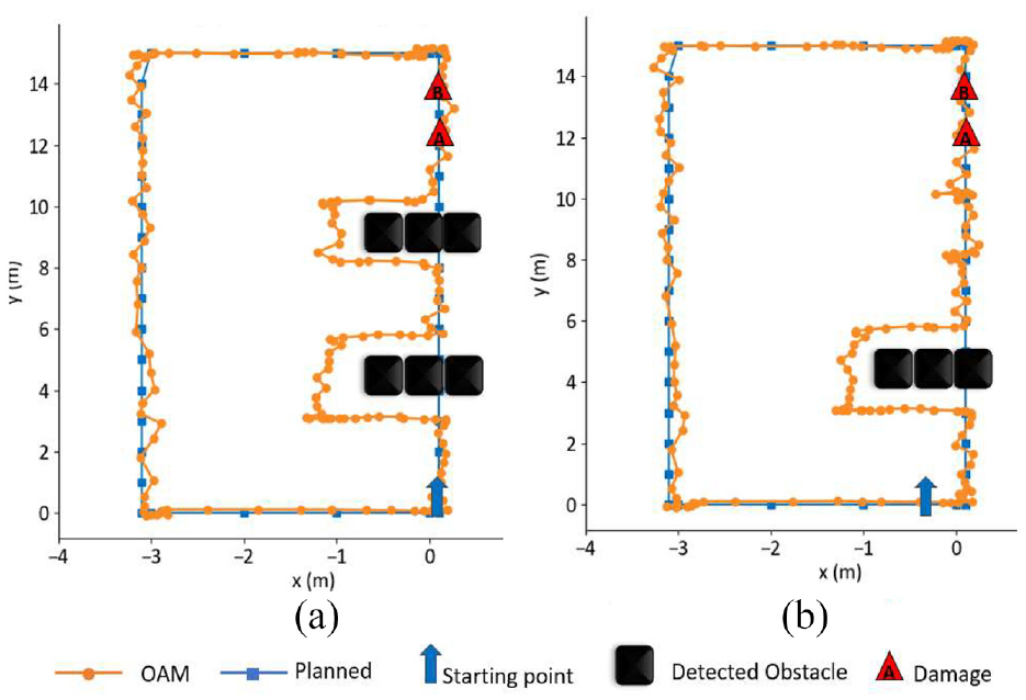
In order to conduct experimental tests to validate the proposed obstacle avoidance algorithm and crack damage detection, we generated a planned trajectory for autonomous navigation of the UAV in the laptop ground station by assigning a series of waypoints (expressed as blue lines, as shown in Figure 17). The distance between each waypoint was set as 50 cm. Two and three groups of obstacles were set, which are illustrated as black rectangular boxes. The locations of detected cracks in the concrete floor are illustrated as red triangles. Specific waypoints were expressed as red circles in obstacle scenario 1. As shown in Figure 17, two cases of obstacle scenarios were well avoided by using our proposed OAM. The orange lines express the trajectory to avoid obstacles. Also, during the navigations, all three cracks in the concrete floor were detected well. All the dimensions are expressed as cm units.
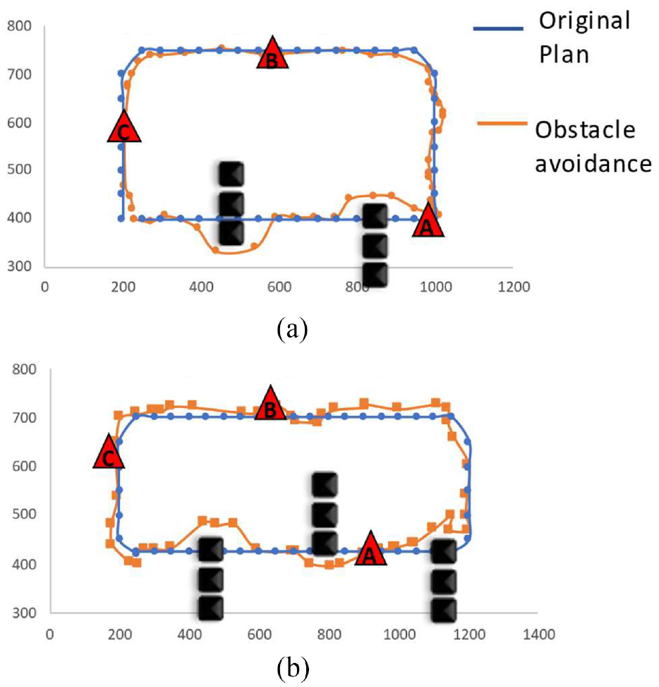
Flight path: (a) obstacle avoidance with two clusters of obstacles, and (b) obstacle avoidance with three clusters of obstacles.
There were three chairs in each group of obstacles, and the proposed OAM (see Section “Obstacle clustering”) operated well during the autonomous navigation. As shown in Figure 18, YOLOv3 detected obstacles successfully, and the K-means clustering algorithm created a group of boxes based on features and converted them into a single obstacle box at waypoints 1, 5, and 11.

OAM performances based on YOLOv3 and K-means clustering at waypoints 1, 5, and 11.
As comparative study, our approach was compared to existing deep learning-based monocular depth estimation algorithms such as MonodepthV2 (Godard et al., 2019) 32 and AdaBins (Bhat et al., 2020). 33 Using the two tests, 20 image frames with obstacles in the scenes from each autonomous navigation were selected to compare the performance of the obstacle identification/clustering. A total of 40 image frames were used as the input for the three methods and tested, as shown in Figure 19.
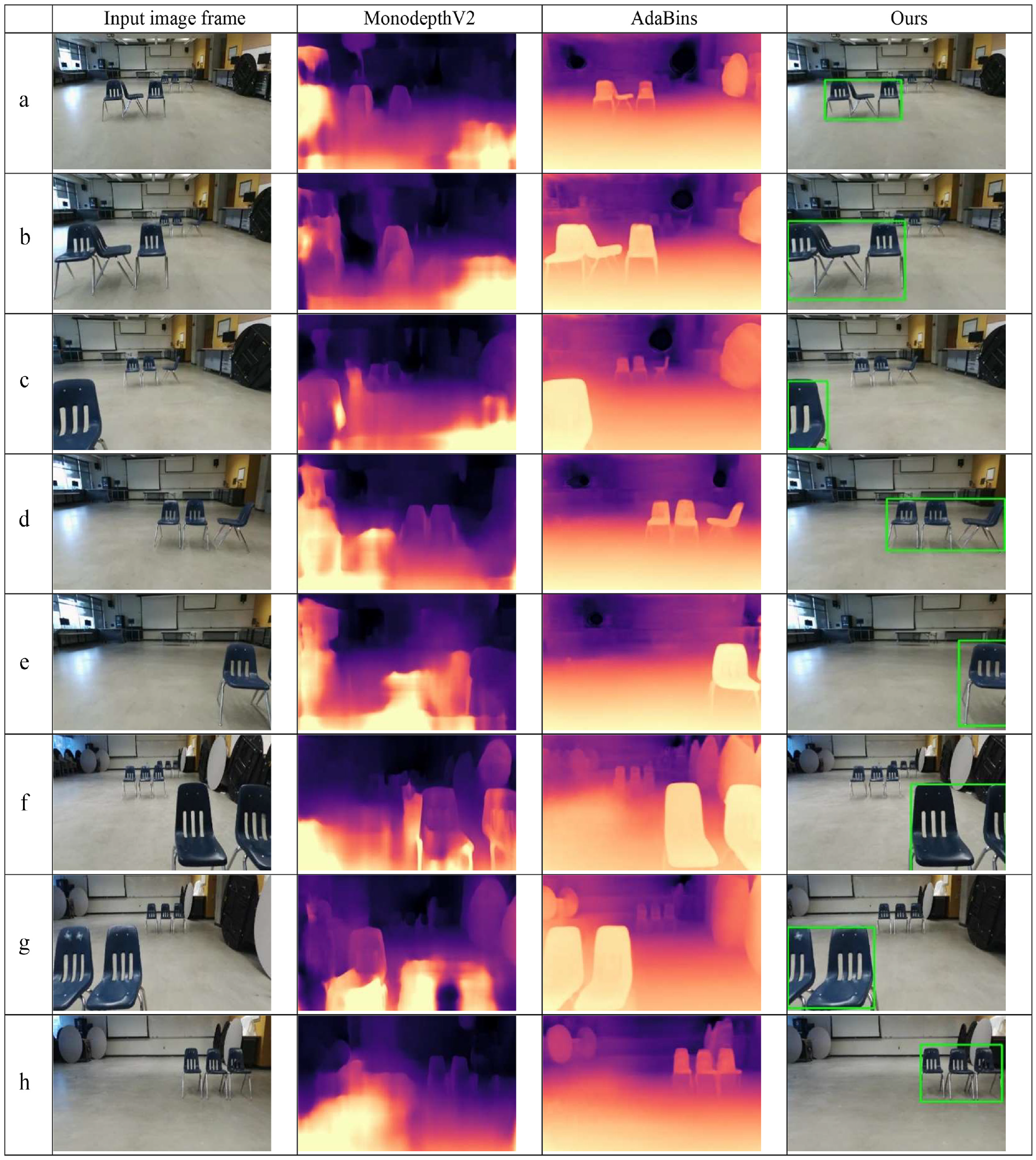
Detected obstacles in three methods: (a) Farther away obstacles in center, (b) Closer obstacles, (c) Multiple obstacle groups, (d) Farther away obstacles to right, (e) Partially visible obstacle, (f) Two closer obstacles, one partially visible, (g) Two closer obstacles, one partially visible to left, and (h) Three obstacles fully visible to right grouped.
Our object clustering algorithm and AdaBins worked well to identify obstacles in various scenarios in terms of location within the image frame. However, MonodepthV2 failed to identify the chairs as shown in Figure 19(a) to (d). Furthermore, empty spaces were detected as obstacles consistently in Figure 19(a) to (h).
While MonodepthV2 failed to provide the proper quality of the depth map to identify obstacles, AdaBins and Ours achieved very successful results. To evaluate the performances, we use the three most common evaluation metrics: precision, recall, and F1 score, as expressed in Equations (30)–(32). True positive, true negative, false positive, and false negative cases are abbreviated to TP, TN, FP, and FN, respectively.
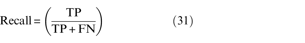
All the calculated evaluation metrics are tabulated in Table 3. The results of 40 images were manually checked. There were two obstacles in scenario 1 and three obstacles in scenario 2, as shown in Figure 17, which appeared in the 40 image frames 95 times. AdaBins and Ours showed satisfactory results in these two cases of autonomous navigation with different obstacle scenarios, as presented in Table 3.
Evaluation result of obstacle state for each algorithm
FPS: frames per second.
However, the processing speed of the AadBins was just 0.3 FPS, which may delay the overall inspection process due to the low speed of the OAM, since videos are commonly 30 FPS. However, our algorithm was still 10 FPS using an old 1060 GPU. Also, as shown in Figure 19(a), (b), and (d), AdaBins could not detect the legs of the chairs. It can be potentially dangerous in infrastructure inspections if small, thin obstacles are not properly detected during navigation for monitoring.
STRNet results for indoor case
Figure 20 shows the three different cracks presented in Figure 17 as red triangles (a, b, c). The cracks in the images from the UAV camera are seen as very unclear and blurry due to the vibration of the UAV. The results of the Deeplab v3+ and MobileNet v3 suffered from loss of the crack pixels throughout the line of the cracks (Figure 20(a) and (c)). Attention U-Net showed good results in image c, but it missed the end of the crack in images a and b. Among these algorithms, STRNet showed very good performance in all images, with 91.8% mIoU.
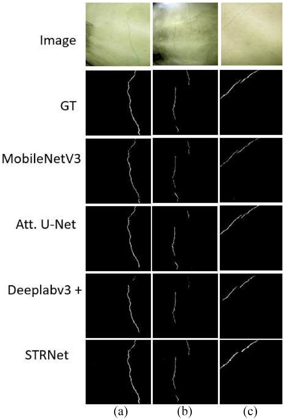
Comparison between MobileNetV3, Attention U-Net, Deeplab v3+, and STRNet: (a) crack image 1, (b) crack image 2, and (c) crack image 3.
Outdoor experiments
After obtaining successful results from indoor experiments, outdoor experiments were performed in a multi-level parking structure in the Fort Garry campus of the University of Manitoba. The top floor was used to conduct the autonomous UAV experiments. The wind direction was along the southeast, with wind gusts of more than 30 km/h.
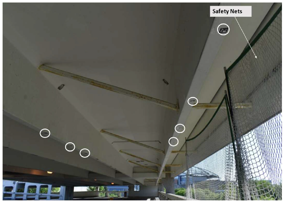
The average height of the UAV’s planned waypoint was 7 m from ground level. This natural, real-world environment was used to validate the robustness of the developed systems. ArUco markers were installed at every 1 m on the ceiling in the designated section, as shown in Figure 21. For safety, nets were installed instead of windows. In the experimental setup, the UAV was under the impact of strong to medium wind gusts. Different sets of planned waypoints were used to confirm the validity of the proposed method of UAV control via ArUco markers. The overall outdoor experiment area is shown in Figure 21. During the experiments in the parkade garage, the lighting conditions were challenging due to the low light levels and the presence of occluding lights. These conditions can affect the performance of a camera-based system, as the low light levels can make it difficult for the camera to capture clear images, and the occluding lights can create glare and shadows that may obscure objects of interest. These markers are designed to be easily detected by a camera system, even when the lighting conditions are poor.
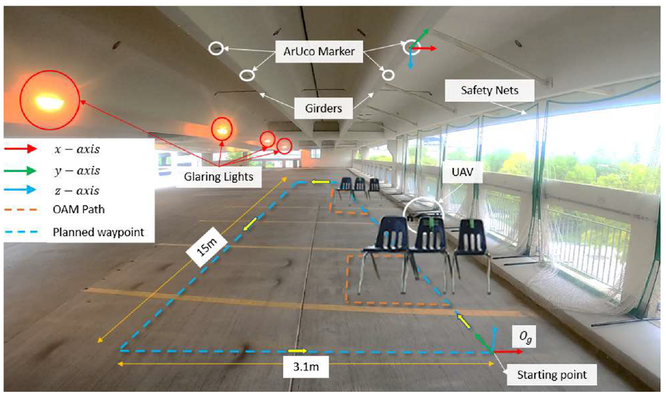
Outdoor experimental setup using the ArUco-based navigation system with chairs as obstacles.
Yaw control of UAV
The most important feature of using computer vision-based ArUco marker-based localization is the robust estimation of yaw
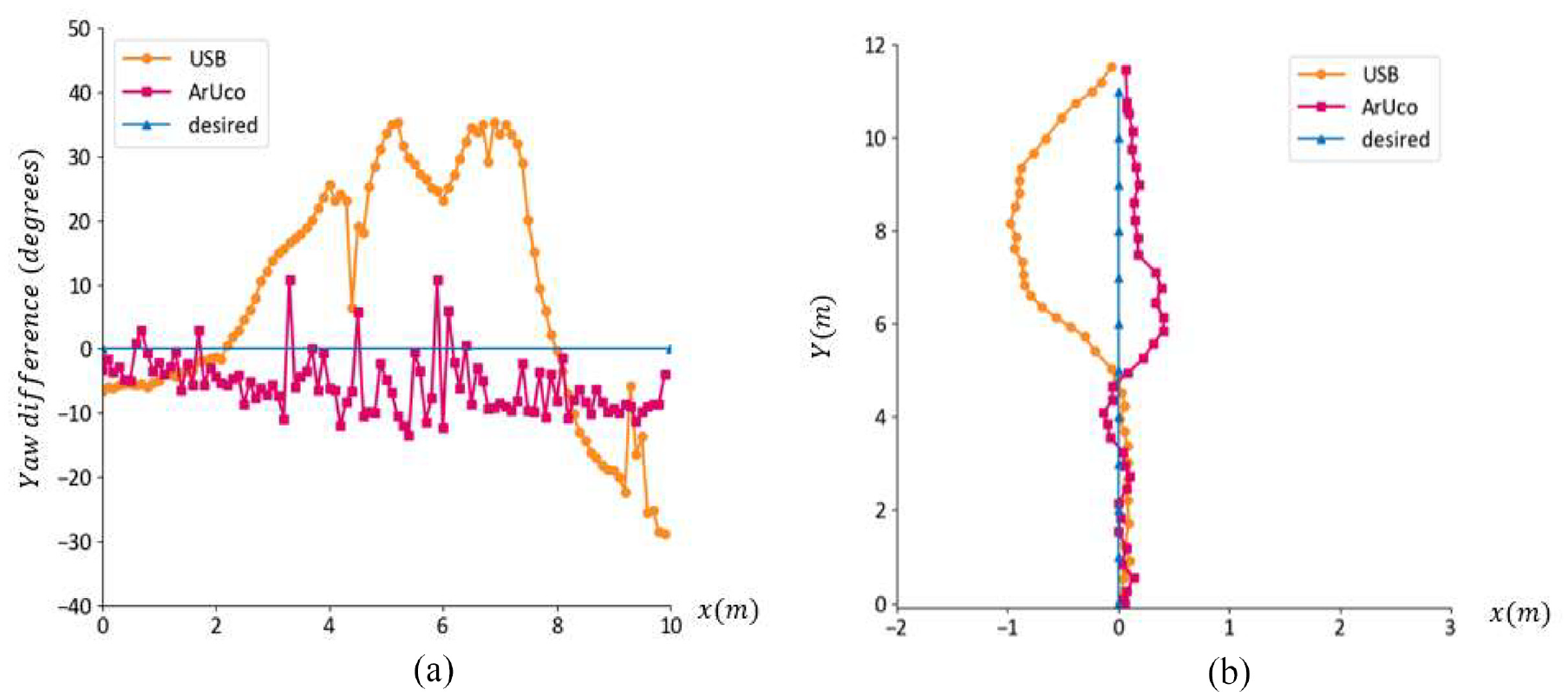
Comparing the performance of (a) deviation in yaw control and (b) deviation in path control for the ArUco marker and USB-based localization methods in an outdoor parking structure.
It was observed that the USB sensors resulted in poor readings when close to steel girders due to magnetic interference. The noisy and unreliable readings from the USB resulted in poor control of the UAV. As a result, the UAV deviated from the planned waypoints when relying on USB data, as shown in Figure 22(b). The yaw deviation
On the other hand, the ArUco marker-based localization was not impacted by magnetic interference and provided the robust yaw values required to control the UAV under the same challenging and complex environment. The deviation
Obstacle avoidance
Based on the comparative studies of the performances of the USB-based and ArUco marker-based localization methods, we chose ArUco marker-based localization for outdoor experimental validation of our proposed OAM.
To avoid obstacles such as chairs, the UAV camera must be able to capture images or video frames from the front side. For this, the camera feed
OAM path versus planned path when navigating through: (a) one group of obstacles, and (b) two groups of obstacles.
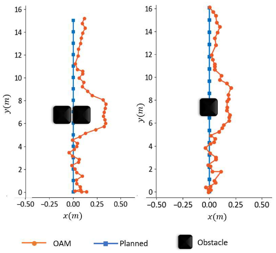
Proposed OAM performance for one and two chairs.
STRNet results for outdoor case
In Figure 25, the performance of STRNet on the data collected from the outdoor parkade is shown. Three images of two separate crack images are presented in Figure 25; their positions are shown as red triangles in Figure 23. Similar to the indoor experiments, the Deeplab v3 and MobileNetV3 performances were degraded as compared to that of Attention U-Net (Figure 25(b) and (c)). Overall, STRNet performed consistently well over all testing datasets and outperformed all the models in comparison. The crack images of Figure 25(a) are from the area indicated by red triangle A in Figure 23, and those in Figure 25(b) and (c) from that of red triangle B in Figure 23.
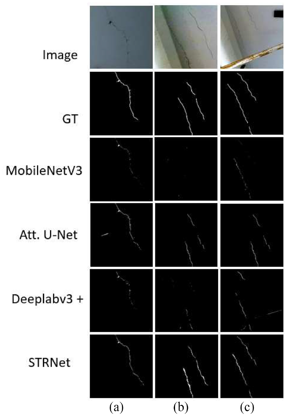
Comparison of crack detection methods using MobileNetV3, Attention UNet, Deeplab v3+, and STRNet on UAV captured images of parkade ceiling: (a) Crack 1, (b) Crack 2, and (c) Crack 3 are highlighted for evaluation during autonomous inspection.
Conclusion and future direction
To develop a reliable autonomous UAV system for SHM, we developed a framework for obstacle-avoiding autonomous flight methods through fiducial marker-based UAV localization. The contributions of the paper are as follows:
A complex autonomous UAV system for SHM was developed by careful integration of a new OAM, a new localization method, and a state-of-the-art real-time crack segmentation method.
A new OAM was developed with YOLOv3 (as an example network, but it can be replaced by any recent version of YOLO) and an obstacle clustering method based on the K-mean clustering method.
The developed OAM was compared to existing methods, and it outperformed with a higher FPS and robust obstacle detection compared to those of the traditional OAM methods.
A new autonomous UAV localization method was introduced for autonomous UAVs for SHM with fiducial ArUco markers. Due to the nature of the ArUco marker, it does not require regular battery charging and is not vulnerable to environmental electromagnetic fields.
The ArUco marker-based method decreased localization error by 67.29% and yaw control error by 60.45% compared to those of the USB method, respectively.
The new OAM, fiducial ArUco marker-based autonomous UAV system, was implemented in indoor and outdoor environments as GPS-denied areas.
The developed autonomous UAV system including a new OAM and localization method was integrated with a state-of-the-art crack segmentation network (STRNet).
STRNet 18 showed superior performance (mIoU 92.5%) compared to recently developed deep CNNs (mIoU 89.1%) for parking structure crack segmentation.
In future work, we plan to integrate new hybrid techniques, such as 3D sensor fusion, to estimate the distance of unknown obstacles for autonomous UAVs and integrate the developed method with a digital twin for real-time damage mapping and management.
Footnotes
Declaration of conflicting interests
The author(s) declared no potential conflicts of interest with respect to the research, authorship, and/or publication of this article.
Funding
The author(s) disclosed receipt of the following financial support for the research, authorship, and/or publication of this article: The research presented in this paper was supported by an NSERC Discovery grant (RPGIN-2016-05923), a Research Manitoba Innovation Proof-of-Concept Grant (4914), and a CFI JELF grant (37394).