
Abstract
Inland navigation structures (INS) facilitate transportation of goods in rivers and canals. Transportation of goods over waterways is more energy efficient than on roads and railways. INS, similar to other civil structures, are aging and require frequent condition assessment and maintenance. Countries, in which INS are important to their economies, such as the Netherlands and the United States, allocate significant budgets for maintenance and renovation of exiting INS, as well as for building new structures. Timely maintenance and early detection of a change to material or geometric properties (i.e., damage) can be supported with the structural health monitoring (SHM), in which monitored data, such as load, structural response, environmental actions, are analyzed. Huge scientific efforts are realized in bridge SHM, but when it comes to SHM of INS, the efforts are significantly lower. Therefore, the SHM community has opportunities to develop new solutions for SHM of INS and convince asset owners of their benefits. This review article, first, articulates the need to keep INS safe to use and fit for purpose, and the challenges associated with it. Second, it defines and reviews sensors, sensing technologies, and approaches for SHM of INS. Then, INS and their components, including structures in ports, are identified, described, and illustrated, and their monitoring efforts are reviewed. Finally, the review article emphasizes the added value of SHM systems for INS, concludes on the current achievements, and proposes future trajectories for SHM of INS and ports.
Keywords
Introduction
Inland navigation, or inland waterway transportation (IWT), is a mode of transportation in which vessels (ships and barges) navigate inland waterways such as rivers and canals, to transport freight and passengers from point “A” to point “B” on land via waterways. 1 These waterways are supported by structures like dikes (also referred to as dykes or levees) and navigation locks which maintain a required depth of water for navigation purposes. There are other structures that aid in transportation and trade, for example, inland ports, harbors, quays, and wharves, that are often connected to seaports through waterways. All of these structures are included in the purview of inland navigation structures (INS) in this article. Proper and timely maintenance of such structures facilitates the smooth functioning of inland navigation. 2 Figure 1 conceptualizes INS across a landmass connecting seaports with inland harbors through waterways.
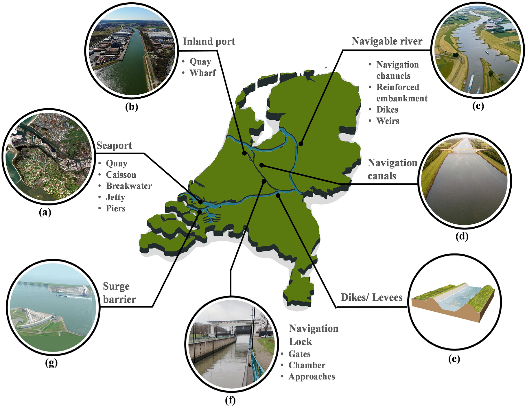
A schematic representation of components found in INS and ports: (a) a satellite view of the Port of Rotterdam (adapted from Placek 3 ), (b) an inland port, 4 (c) the River Elbe with groynes, 5 (d) the Amsterdam-Rhine canal, 6 (e) an illustration of a canal dike, (f) a lift type navigation lock (authors’ photo), and (g) the Maeslantkering surge barrier. 7
INS have a global presence and impact regional economies worldwide. The European Union (EU) maintains 41,360 km of navigable waterways. 8 Europe’s most dense network of inland waterways is found in the Netherlands, where 6000 km of waterways stretch out over only 41,543 km2. This network is vital to the Dutch economy as about one-third of total freight is transported in it. The country also maintains more than 22,500 km of dikes, 9 major ports, such as Rotterdam port, navigation locks, and the world’s largest storm surge barriers. In the United States, the US Army Corps of Engineers (USACE) maintains over 19,000 km of inland waterways, 200 navigation locks, over 900 commercial harbors, and 22,500 km of levees. 10 In China, the length of navigable rivers reaches 126,300 km, which is the largest as well as one of the oldest inland navigation network in the world. 11 Russia has a waterway network spanning 100,000 km, which connects five major sea areas. 12 The network has 16,000 km of artificial canals, 100 locks, and 70 dams. As IWT is an eco-friendly and cost-effective solution for freight transportation, the world bank is promoting the developments of INS in developing countries like India. 13 Compared to transport over railways and roadways, transport over waterway systems is not only more cost-effective but also more energy efficient and generates less air pollution; thus, it is considered a very clean option for transporting goods (see Figure 2). In the United States alone, the IWT saves between $7 and $9 billion a year over the cost of transportation using other modes. 14 The IWT is also recognized as an efficient form of transport in terms of CO2 emission per ton of transported goods. 15
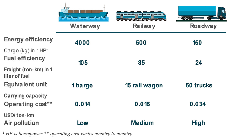
A comparison of inland waterway transportation with railway and road transportation. 16
With such a worldwide presence and economic significance of INS, it becomes important to maintain these structures against unforeseen scenarios that can emerge due to their increased use and changing weather patterns. Some of these structures, such as lock gates, are so crucial that their malfunctioning can have a cascading effect on a stretch of inland waterway. For example, the US Department of Agriculture estimates that any delay due to malfunctioning locks may cost ship operators around $44 million a year. 14 Hence making an inland navigation system resilient against extreme weather events and increased traffic volumes in the future, not only guarantees an uninterrupted operating IWT system but also supports the trade and economy. Also, waterway transport being the least polluting in comparison to rail and road, its improved utilization will reduce the carbon burden from the transportation systems.
Issues and concerns with INS
Studies report issues of aging INS, for example, (1) more than half of the locks and dams in the United States were constructed 50 years ago and are now being used beyond their design life, resulting in their poor state,10,17 (ii) and in the Rotterdam Port, the Netherlands, more than 80% of 74 km long quay walls were completed after World War II, and currently they have exceeded their 50-year design life. 18 Often, the size of such INS makes it impractical to replace or repair the entire stretch at once, due to budgetary and logistical constraints, resulting in lengthy works disturbing their users and local residents.
In the case of seaports, the marine environment accelerates the material deterioration and thus civil structures exposed to such an environment require frequent maintenance to keep them operational. These structures are subjected to corrosion, 19 chloride attacks, 20 wave actions, 21 extreme weather events,22–24 vessel impacts, 25 erosion, 26 and scouring. 27 The effects of deterioration may not always be apparent at the surface of a structure; thus, they might be easily overlooked during a visual inspection, compromising the integrity of the structure. For example, in case of pitting corrosion, the reduction in mass of the structure can be negligible, but the rate of deterioration of the structural integrity in a local region can be significant, resulting in an early catastrophic collapse. 28 In another case, caisson structures were observed to develop undesirable geometrical and mechanical changes resulting from frequent extreme weather events (e.g., large-scale typhoons and storm surges) due to global warming. 29 Such changes are not always visible during infrequent field inspections.
The harsh marine environment and aging of the structures, combined with climate change and frequent extreme weather events, make inspection and maintenance of INS more challenging. The current field practices employ regular visual inspections, in which the identified damage is assessed for severity, and a qualitative index is assigned to it based on the repair requirements. However, visual inspections are ineffective in differentiating between structural and superficial deterioration and identifying damage states. 30 Furthermore, it is limited to accessible locations and, in certain cases, may completely disrupt regular operations of the structure. For example, in a navigation lock complex, a detailed inspection of lock gates/chambers may require complete dewatering which will incur additional costs due to stoppage of transportation. 31 The complexity of lock gates and difficulty in access due to a partially submerged condition make the visual inspection expensive and inefficient detecting early damage. Visual inspections are also not effective in detecting incipient damage and misalignments of gates, which sometimes result in the emergency closure of the entire facility due to a sudden breakdown. Due to the significant expenses and downtime associated with visual inspections, it is normally performed every 5–10 years by the USACE. 31 During this period, the damage can propagate to a critical situation in the absence of repair. Hence, more frequent assessment of INS would be desirable. Sometimes inspections are supported with laboratory testing. For example, core samples are extracted from the concrete structures to evaluate the reasons for deterioration and estimate the remaining service life.32,33
Other major factors urging for frequent assessments of INS are as follows: (i) changing weather patterns causing floods and droughts, 34 (ii) a rise in extreme weather events like storm surges 35 , and (iii) an increase in the inland water traffic and size of vessels, 36 which may causes misuse of the navigation structures. These factors compromise the integrity of INS and their service life. Other concerns are land subsidence, 37 seismic activities, 38 and vessel impact 39 which can also impede the performance of navigation structures.
In structural health monitoring (SHM) collected measurements such as loads on and response of structures are analyzed for early changes/deviations from the set baseline conditions of the structure. SHM allows for continuous or frequent evaluation of the structure’s integrity; therefore, it can (i) be more insightful than visual inspections (ii) and improve the climate resilience of important structures. 40 SHM research in civil engineering focuses predominantly on bridges, dams, and wind turbines. INS and ports are also important components of the civil infrastructure, requiring continuous operations and timely maintenance, which SHM can support. This article reviews challenges and developments in SHM of INS and ports.
Recent projects on the SHM of INS and ports
In the last decade, requirements for monitoring and maintenance of INS and ports have been addressed and presented through collaborative projects and reports. 15 It has been envisioned that INS and ports have to be future-ready for growing global trade and climate change. The project NAIADES-III by European Commission (EC), released in 2021, calls for an innovative action focusing on implementing novel techniques and technology in IWT. 15 According to the International Research Centre on Artificial Intelligence (IRCAI), which is an organization working under the auspices of UNESCO, the water industry has increased the installation of sensors on infrastructure, but lacks the framework to take benefit of the obtained data. 41
The European inland waterway expands approximately 41,000 km through 25 EU member states, conveying around 150 billion ton-km of freight each year, which is 6% of EU freight. 42 It has a huge potential to decarbonize the current transportation system. The EC suggests shifting toward IWT, as it is more energy efficient, safer, and quieter than other modes of transportation and is almost without traffic congestions. 42 The NAIADES-III also calls for future-proofing the European IWT. A well-functioning system necessitates proper operation of its components, which in this case are the civil structures that make up an IWT system. The EC further highlights the significance of regular investments in waterway infrastructure, such as canals, rivers, bridges, and locks, to prevent their decline and enhance their long-term performance.
The World Association for Waterborne Transport Infrastructure (PIANC) calls for continuous monitoring of INS that are close to the end of their design life and, thus, supporting their real-time operations. PIANC defined the main objective of SHM as quantification of the risk and reliability for making important operational and financial decisions regarding the functionality and safety of INS. PIANC formed a working group (WG 199 43 ) to document international best practices of SHM for port and waterways infrastructure. The working group seeks to develop a knowledge pool in the domain of SHM of port and waterway structures, collecting inputs from asset managers, consultants, field engineers, and other concerned organizations. In another call, the EC aims to digitize the IWT to improve the navigation and management of traffic 44 , thus increasing the number of vessels in the navigation systems which is recognized as the main stressor for scouring. 45
Some demonstrators of major SHM applications exist. UrbanFlood (an European project) has developed an early warning system using artificial intelligence (AI) for calculating the probability of a dike breach and the amount of flooding. 46 The USACE is working on SHM of navigation locks under a project Structural Monitoring and Analysis in Real-Time of Gates (SMART Gates). The developed system has been employed at six locations in the US, with up to 300 sensors per location collecting strains, temperature, and tilt measurements. 47 Another project (Smart-Port) currently implemented in the largest European seaport, the Port of Rotterdam, is on monitoring the condition of quay walls, that are currently older than 50 years. 18 The scope of the project involves assessing the feasibility of utilizing the quay walls 20 years beyond their design life, which is 50 years. The project further investigates the effect of climate change on quays, and the effects of change in their use due to the development of additional facilities, larger vessels, and increased traffic on the quay walls. 48
Even though the abovementioned projects have highlighted the significance of SHM of INS, only a few case studies on SHM of such structures exist in the literature. For example, a wharf is considered one of the most critical structures in port facilities; still, in a review, EC COST Action on SHM of civil structures, the SHM of wharves encompasses only 15 case studies and close to 30 research articles. 49 In the case of navigation locks, the SHM is gaining popularity, but the process of SHM is still not automated. 31
SHM can improve the resilience of INS toward future changes and addresses several sustainable development goals (SDGs) set up by the United Nations general assembly, for example, industry innovation and infrastructure (SDG 9), development of sustainable cities and communities (SDG 11), climate action (SDG 13), and partnership for the goals (SDG 17). 50
Review organization
This section identified INS and briefly discussed the importance of their SHM. Calls for actions by various international organizations were mentioned stating the importance of SHM of INS. The Section “Sensors, sensing technologies, and approaches in SHM” explains the sensors and sensing technologies used in SHM of INS in the reviewed literature. Readers who are well familiar with sensor, sensing technologies and their approaches can proceed to the next sections, which discuss the SHM techniques implemented or under development for INS and ports. To this end, INS are classified under four Sections, “Port structures,”“Waterways and protective structures,”“Navigation locks,” and “Accessory structures.” Also, the stressors causing the damage to the structures are explained. The Section “Port structures” reviews the SHM techniques implemented for wharves and quays, coastal structures like breakwaters, and protection works. “Waterways and protective structures” discusses monitoring of navigation groynes, canals, and dikes. “Navigation locks” cover techniques used in the monitoring of the lock complexes. Being critically important structures in waterways, locks have been monitored extensively. Hence, the techniques are further discussed separately as local and global techniques. “Accessory structures” discuss SHM of other structures crucial in an inland navigation system. The Section “Added value of SHM systems for INS and ports“ is also provided. The review is completed with the Section “Conclusions and future outlook”, which concludes the state-of-the-art developments and provides an outlook for the future of SHM for INS and ports. The primary aim of this review is to identify the structures associated with inland navigation, explore the state-of-the-art developments in their monitoring, and identify the challenges associated with their implementations. Although dams in navigable rivers can be considered as a part of INS, recent reviews of (i) health monitoring of concrete dams51,52 and dams under various environmental conditions, 53 and (ii) dam monitoring data analysis methods 54 already exist, and, therefore, SHM of dams is not reviewed in this paper.
Sensors, sensing technologies, and approaches in SHM
SHM of civil structures can be divided into two basic stages. The first stage is employing sensors or sensing technologies to record structural parameters associated with the condition (load response mechanism) of the structure. The second stage deals with assessing the performance and safety of the structure based on the identification of damage-sensitive features from the acquired data. This section discusses sensors, sensing technologies, and measurement interpretation approaches found in the literature for SHM of INS and harbors. SHM processes, which entail data science and engineering, modeling, and data management, are not fully covered in this review; however, brief discussions wherever they are deemed necessary are given. Reviews of the data science and engineering used in SHM of civil structures can be found in Bao et al., 55 Malekloo et al., 56 Catbas, 57 Entezami et al., 58 Moughty and Casas, 59 Catbas and Malekzadeh, 60 Entezami et al., 61 Kim and Queiroz, 62 and Entezami et al. 63
Sensors are fundamental elements of SHM systems. They measure physical (e.g., displacements, accelerations, strains), environmental (e.g., temperature, humidity), and chemical (e.g., chloride contamination) parameters. Continuously collected parameters of interest form measurement time histories or signals. Signals are then pre-processed and analyzed using adequate algorithms and machine learning techniques to detect and characterize changes in the monitored structure. Sensors and sensing technologies are classified according to measured parameters, physical phenomena, and their proximity to the host structure. In this section, they are classified based on their proximity to the structure as, contact and noncontact sensors, and remote sensing (see Figure 3). In literature, noncontact methods are also kept in the purview of remote sensing. However, they can be classified differently based on the requirement for physical access to the site or areas of observation/monitoring. The size of INS and harbors ranges from a few meters to hundreds of kilometers. For this reason, noncontact sensors are separated from satellite-based remote sensing.
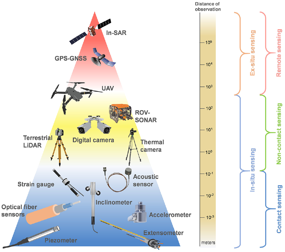
A fuzzy classification of sensors and sensing technologies used in the monitoring of INS and ports based on the observation distance from the structure to be monitored.
Contact sensors
Contact sensors (also, contact sensing) are basic sensors that need to be installed on or very close to the host structure. In general, contact sensors are installed permanently. They require power, wired or wireless data transmission, and physical protection/shield. Usually, a single sensor can take measurements at a single point, such as a strain gauge (SG) or an accelerometer. Such sensors are referred to as single point sensors. The advent of fiber optic sensor (FOS) technologies offers measuring at multiple points (distributed sensing).
Displacement sensors measure, for example, movements of joints or enlargements of cracks within a structure. Displacement sensors operate on different principles:
Linear variable differential transformers (LVDTs) work on the principle of electromagnetic (EM) interference. They have robust design and provide high-resolution measurements for long-term monitoring tasks. 64
Crack meters or joint meters are displacement sensors intended for a specific function, such as monitoring widths of cracks in concrete structures. 65
Vibrating wire sensors have a tensioned wire, which is fixed between two anchor points in a sealed metallic tube. The wire is constantly triggered, and its vibrating frequency is measured via a read-out unit. The frequency of the wire can be calibrated with displacement or strain measurements on the host structure.
Multi-point bore-hole extensometers (MPBXs) measure displacements between multiple points. They are primarily used for geotechnical applications under embedded conditions, such as monitoring movements of rock mass or foundation/retaining soil. MPBXs are also applicable for monitoring creep/expansion of aging concrete. 66
Eddy current sensors use the principle of EM induction. They can be utilized to perform high precision measurements in harsh industrial environments. They are used to measure (i) start of offsets in large moving components of load retaining structures, such as surge barriers 67 or (ii) crack growth in metallic components. 68
The first-generation SGs have a thin metallic zig-zag foil sandwiched between two insulated sheets. They measure strain at the location where a SG is attached to the host structure from the change in electrical conductance of the metallic foil. The electrical resistance of SGs varies with changes in dimensions of the metallic foil, which are transferred from the host structure. A change in resistance is converted into voltage using the Wheatstone bridge, and it is read by a datalogger. Commercial SGs are commonly available in 120 and 350 ohms. The resistance of SGs also changes with the surrounding temperature, hence either a temperature sensor or a dummy SG is needed along them to provide for temperature corrections. The two primary SG installation techniques are welding and bonding. In the first technique, a weldable SG is attached to a metallic surface with a resistance spot welder. In the latter technique, an industrial adhesive is used to bond a SG to the prepared surface of the structure. SGs bonded with adhesive can be delicate and subject to delamination and drift over time. 69 Weldable SGs are rugged and robust. They are explicitly developed for use in long-term SHM in challenging environments of large-scale civil infrastructure. SGs have been used in the analysis of defects in metallic structures such as navigation lock gates and ship lifts. 70 Strain can also be measured using vibrating wire SGs (VWSGs), which are based on the change in the vibrating frequency of tensioned wire. 71
Accelerometers are used to measure motions of a body with the respect to an inertial reference frame. In principle, they have a seismic mass that moves with the motion, a transducer element (e.g., Piezoelectric) attached to the mass, and measuring electrodes. Commercially available electromechanical accelerometers are based on piezoelectric, piezoresistive, or capacitive elements, among which piezoelectric accelerometers are the most common. They are durable, inexpensive, and widely available; however, they are ineffective in measuring very low-frequency vibrations. 72 Microelectromechanical systems (MEMSs) capacitive accelerometers are the cheapest and smallest in size. Accelerometers are a key instrument in determining vibration parameters of a structure, which are closely associated with the stability of the structure.29,47,73–75
Inclinometers or tiltmeters measure a slope angle of a surface with respect to the direction of gravity. Digital inclinometers are based on MEMS or bubble level. They are widely used in single- and dual-axis modes. Examples of applications of inclinometers for INS are for measuring anomalies in the hoisting of tainter gates, 76 changes in slope in dikes, 77 and bearing movements in surge barriers. 67
Load cells convert mechanical forces such as compression, tension, torque, or pressure into quantifiable electrical signals. The primary sensing element in load cells is a SG bonded on a metallic body of a known elastic modulus. The entire setup is encased in a hermetically sealed shell. Any load experienced by load cells generates a strain in the ESG, which is then converted into the load value. The piezoelectric-based load cells generate voltage instead of resistance, making them very suitable for monitoring dynamic loads. They are used for measuring operational loads on structures, for example, hydraulic load on a particular member of a navigation lock gate,47,78,79 tension in cables,75,76,80 and torque in rotating elements.
Pressure sensors measure hydraulic loads on structures or piezometric heads in geotechnical structures such as dikes. 81 They are commonly made of piezoelectric elements which generate voltage when a pressure/force is applied. Piezoelectric-based sensors can only measure the dynamic pressure. The static pressure is best measured with capacitive or SG-based pressure sensors, which have the capacitive or resistive element bonded to a tensioned wire attached to an outer diaphragm. The pressure exerted on the diaphragm pushes it inward, thus changing the tension in the attached wire. This change is measured and calibrated for values of the pressure.
FOSs can measure temperatures, displacements, strains, and accelerations at multiple points along the length of an optical fiber. Optical signals (i.e., light) are used instead of electrical signals for measurement, therefore making FOS resistant to EM fields, which can affect measurements of other sensors such as ESGs. The optical fibers are based on distributed Bragg reflector, that reflects or blocks a certain wavelength of light. The reflected wavelength is characterized by the index and period of a refraction, which are functions of a change in temperature and/or strain around the fiber.82,83 Multiple gratings are possible in an optical fiber. Such FOS are referred to as fiber Bragg grating (FBG) sensors. They have a wide range of applications, especially for monitoring spatially extended structures such as quay walls,84,85 caisson breakwaters, 83 and dikes.81,86,87 Fiber optics can also function as a linear temperature sensor, and the technique is called distributed temperature sensing (DTS). The DTS can measure temperature changes with a resolution of 0.05°C even at 1 km sampling distance. 86 Long-period fiber grating (LPFG) sensors can detect chemical as well as physical changes in their surroundings. High-quality helical LPFG (HLPFG) sensors due to the method of their formation and physical properties have a broader measurement range and higher sensitivity to torsional parameters than LPFG. 88 In damp and harsh environments, optical fibers can developed physical damage.
Temperature, humidity, and corrosion sensors are required while assessing the structural integrity (particularly, detecting seepages) of dikes.49,89 For example, underground seepage can have a detrimental effect on a structure, thus monitoring parameters related to it can give an early alarm. 49 Temperature measurements are crucial for correcting measurements of some sensor (e.g., VWSG). Temperature can be measured with resistance-based thermistors or thermocouples, which give a change in voltage at the junction of two metal wires when temperature changes.
Humidity sensors work on the principle of the electrical capacity. They have a strip of metal oxide between measuring probes. The electrical capacity changes together with relative humidity. Humidity sensors have a significant contribution for monitoring systems of dikes.90,91 INS and harbors are located in harsh marine conditions, which escalates the corrosion rate in concrete rebars or other steel members. Monitoring corrosion is therefore mandatory.92,93 Generally, corrosion sensors work on two principles: electrical resistance and electrochemical potential. 49 The loss of mass induced by the corrosion increases the electrical resistance between two fixed reference points; thus, the resistance becomes a suitable indicator for the quantification of corrosion. Sensors based on electrical resistance are called resistivity sensors. They are used along with humidity and temperature sensors as the resistivity of the concrete cover depends on temperature and concentration of chloride ions in the medium, which is generally water for concrete structures. 94 In the electrochemical method, the electrochemical potential of a silver/silver chloride electrode is measured against a stable reference electrode, usually, a graphite rod, which is insensitive to free chloride and hydroxyl ions. 95 The measured potential has a linear relation with the chloride activity in harsh marine environments. In addition, resistivity sensors get short-circuited due to the damp environment. Also, the life expectancy of resistivity sensors is limited since the service life of the reference electrodes (silver/silver or chloride/potassium type) is certified for up to 10 years, after which they would cease monitoring.
Non-contact sensing
Contact sensors require time-consuming installation, environmental protection, regular maintenance, and repairs, which can be overcome using noncontact sensors/sensing. 96 Non-contact sensing offers collecting many types of measurements. For example, temperature and displacements can be measured without coming into the contact with the host structure, thus enabling SHM at both local and global levels. 97
Computer vision (CV)-based monitoring is the process of monitoring structures using digital imaging technologies. CV can be compared to human vision, but with capabilities of data storage, pixel-level observation, and qualitative and quantitative image comparison. CV-based systems can be set up without the need of working at heights and causing disruptions. Conventional SHM methods can be applied to collected measurements. 98 Wide and varied ranges of digital cameras and lenses enable CV-based SHM of structures at both local and global levels. Applications range from straightforward tasks (e.g., underwater inspections or drone-based surveillances) to complicated tasks (e.g., object identification and feature extraction). Unmanned aerial vehicles (UAVs) are used for inspecting civil structures in remote or difficult to access areas. Research studies envision a completely automated facility inspection and monitoring with autonomous robots/drones equipped with CV-based systems. 99 Advancements in camera technologies, increasing computational capabilities, and available of commercial drones open opportunities for CV-based SHM to become very convenient and effective, allowing practicing engineers to use it routinely. 100
For SHM at the global level (measuring structural displacements), digital cameras on fixed platforms (or tripods) are set up away from structures and focused on them or their elements. A camera field of view is adjusted as per measurement resolution requirements or monitoring objectives. An image frame can consist of millions of pixels. Computational resource can be reduced when defining a region of interest, within which targets (objects of interest) are tracked with suitable techniques such as the template or feature point matching techniques. 101 Accuracy and resolution of measurements depend on the number of pixels and the sharpness of the image, and the deployed image processing algorithm. A very high-resolution device can measure displacements at the micron level at the cost of increased computational requirements. 102 Unlike contact sensors, CV-based systems do not have a physical limitation of taking measurements in a small region of interest, thus deformations at several locations on the structure can be acquired using a single camera. 103 CV-based SHM can capture static, dynamic, and quasi-static response of structures. For local-level applications of CV-based SHM (e.g., the detection of cracks, fracture, and corrosion) algorithms are trained using machine learning techniques to identify and quantify features in images and videos.103,104 In this review, applications of CV-based SHM in monitoring INS such as lock gates, dikes, and revetments are discussed. CV-based SHM techniques at local and global levels of civil facilities are reviewed in Dong and Catbas 98 , Xu and Brownjohn 101 , and Ye et al. 105
Light detection and ranging (LiDAR) is a noncontact sensing technique used to measure distances in the range of a targeted object or surface using laser pulses. Measurement points are coordinates in the 3D space forming a point cloud, which is converted to a digital elevation model. LiDAR has been employed for monitoring spatial structures such as beach nourishments, 106 dikes, and slopes. LiDARs can be mounted on stationary or mobile platforms, as well as on terrestrial or aerial devices. When LiDAR is installed on a UAV, the scanning technique is referred to as airborne laser scanning (ALS). When it is fixed to a stationary ground platform, it is referred to as terrestrial laser scanning (TLS). A TLS offers measurement of tens of millions of points in a 3D space with an accuracy of a millimeter. 107 It is mostly used in morphological studies of geological structures such as rocks, beaches, coastal dunes, and river banks. Mobile laser scanners can quickly cover large areas, whereas static laser scanners generate denser point clouds as they collect many more points per square meter than mobile laser scanners. A dense point cloud generates high-resolution models, which provide better volumetric and areal measurements. A mid-range TSL can measure from a range of 4 to 800 m, and can be coupled with a digital camera to generate a color model. 108
Fast ground-based synthetic aperture radar (SAR) is another radar-based system that is commercially available and can measure deformations in slopes of dikes with an accuracy of 0.1 mm from a distance of 4 km. 109 It uses real-time processing of interferometric images to measure distances with sub-millimeter accuracy. The system was tested in the IJkdijk project, the Netherlands, where it measured accurately deformations in the dike slope when the water level was increased on the opposite slope. 110
Sound navigation and ranging (sonar) transducers use sound propagation to measure distances and identify the location of objects in submerged conditions. They generate acoustic pulses and simultaneously record time to reflect from a target. This way the distance between a target and the transducer is estimated. This technique is called echo sounding. Multibeam echosounders or acoustic cameras use an array of transducers to create a multibeam swath, which can generate high-resolution 3D maps of underwater structures during bathymetric surveys. 111 Acoustic cameras mounted on remotely operated underwater vehicles (ROUV) or a surface boat can provide an ample information about conditions of submerged structures than visual inspections, particularly in turbid waters with limited visibility. The speed of sound, however, is not always constant along a water column, thus requiring the calibration of equipment according to surrounding conditions.
A side-scan sonar technique is used in 2D underwater imaging. It creates underwater images by measuring the intensity of reflected chirp signals rather than time as in echo sounding. The images along a path with recorded global coordinates are stitched together to generate an underwater map. Sonar imaging generally uses sound pulses with a frequency between 10 and 800 kHz. Commercially available devices, known as fish finders, can operate at up to 1200 kHz. High-frequency chirp signals can generate high-resolution images; however, they are only effective at relatively shallow depths.112,113 Both echosounder and sonar imaging have been extensively employed in monitoring scouring and erosion in bridges, 114 shoreface nourishments, 115 quays, breakwaters, 116 offshore wind farms, 117 and lock gates 118 . Sonar is a well-established technique used in underwater inspections of marine and coastal structures.
Geophysical methods. Electrical resistivity tomography (ERT) is a popular noninvasive geophysical method for monitoring geotechnical conditions of dikes. The technique uses the measurement of resistivity, which is sensitive to seepage, temperature change, and clay content between the electrodes fixed along the crest of a dike.89,119 It can even perform imaging of dikes down to the bedrock level. 120 Other geophysical methods used in dike inspection are EM and seismic methods, and ground-penetrating radars (GPRs). GPRs transmit short EM pulses (100–500 MHz) into the ground and receive reflected waves from different interfaces. GPRs provide higher spatial resolution than ERTs and seismic methods. 121 However, their measurement is limited to shallow depths, which is sufficient for monitor animal burrows and underground piping in dikes. 122
Remote sensing
Contrary to in situ monitoring, SHM using remote sensing entails observing and measuring a structure or phenomenon on the ground surface without physically contacting or visiting the facility. Remote sensing, in its broadest sense, refers to the use of satellite or aircraft-based sensing systems. The technology is currently being extensively investigated for monitoring deformations in spatially extended structures such as dikes, groynes, breakwaters, and railway tracks.
Interferometric SAR (InSAR) is a technique in remote sensing, which uses phase differences between two or more SAR images to develop digital elevation and ground subsidence maps. It has been employed for measuring ground deformations induced by calamities such as earthquakes and volcanic eruptions. It (i) has a precision comparable to laser and optical measurements (in millimeters), (ii) can cover a large area in one swath, (iii) and is not affected by weather and the absence of light. 123 Therefore, InSAR is suitable for disaster response applications. Monitoring includes a comparison of interferometric data acquired at intervals when satellites passed over locations of interest. Time-series analysis of InSAR data is a multifunctional tool for many earth observations. Permanent or persistent scatterer interferometry (PSI) is a time-series analysis approach for InSAR data that is often considered the most effective remote sensing technique for measuring displacements of structures. 124 PSI uses phase information of a small subset of radar targets that is free from any decorrelation (temporal and geometric) effects for interferometric measurements. 125 It can record displacement velocity between 0.1 and 2 mm/year at multiple points in a high spatial resolution. The primary benefit of the technique is that it can provide information about global structural stability as well as the stability of the surrounding environment. 126
Global positioning system (GPS) is a widely accepted technique for measuring 3D displacements of large areas.127,128 GPS uses a global navigation satellite system (GNSS) receiver to track real-time kinematics. Its accuracy is 5–10 mm for horizontal (i.e., on the plane of Earth’s surface) displacements; however, due to the high noise profile, real-time vertical (i.e., in the zenith) measurements are challenging. 129 It requires the installation of single or multiple GPS antennas in the area of monitoring. Researchers have attempted to apply GPS monitoring for spatial structures such as coastal dikes, 91 breakwaters, 130 embankments. 131 The GPS data can enhance the precision of InSAR for structural monitoring; thus, they are frequently employed in conjunction with each other.132,133 GPS has the advantage of monitoring data in real time and is unaffected by vegetative growth, which is not possible with InSAR monitoring. 134 The integrated use of both remote sensing techniques has proven to be a promising alternative to the traditional land surveying.
Summary. The improvement in the accuracy of satellite-based interferometry, remote sensing offers monitoring civil structures such as dikes, quay walls, and coastal protection structures. The InSAR technique for monitoring ground deformation can be pivotal in performing SHM in most structures where the movement of the ground is a crucial parameter. The SAR satellites are constantly orbiting the earth and generating high-resolution Big InSAR Data. 124 The development of simple InSAR products for processing Big Data and expansion of computational facilities holds a promising future for InSAR-based SHM.
SHM approaches
In principle, SHM is used as a “tool” to ensure integrity and safety of structures, detect onset of damage, and estimate deteriorations in structures. 135 But there is no specific set of rules for performing SHM of a structure. Over the years, researchers and practitioners have developed several approaches to achieve objectives of SHM. Developments in sensing technologies, wireless networks, data science, and computational techniques have contributed to the evolution of these approaches. There is no single approach that can be used to execute SHM on a certain structure. The selection of a suitable approach is subjected to requirements of maintenance, surrounding environment, and availability of skilled labor and resources. This section discusses SHM approaches of INS and harbors.
Strain-based approaches are the most basic strategies applied in SHM of civil structures. 71 In these approaches, only strain values are used as input. 136 Strain is directly proportional to stresses and deflections in a structure; hence, it acts as an effective measure of structural performance. In addition to SGs, which are commonly used to measure strains and are reliable, noncontact techniques such as CV-based measurement 137 are gaining popularity in these approaches. The presence of damage is indicated by strain values that differ from predefined references (baseline conditions). In addition, strain-based SHM is beneficial for providing decision support, when loadings on structures are increased. 138 Sensing technologies of the next generation, such as optical fiber strain sensors and digital image correlation, have enabled the measurement of strains at multiple points, hence supporting and enabling SHM at the global level.
In displacement-based approaches, structural displacements are monitored. Displacements of a structure or its element within a specific range can be an indicator of structure’s integrity and safety. 139 In case of a rigid body movement, a structure may observe displacements in forms of settlement, sliding, opening, or tilt: (a) caissons may settle due to changing ground conditions, (b) dikes may tilt or change their slope, (c) rock armors may displace from their original positions, and (d) and mechanical components may reduce in dimensions due to wear and tear. Displacements across multiple points on a single plane reflect a deformation of its surface. Such displacements are difficult to observe during visual inspections. An example of sensors and sensing technologies that measure minute changes due to displacements are LVDTs, sonars, LiDARs, and InSARs. These technologies fulfil the same requirement of measuring displacements, but at varying scales. When monitoring geotechnical phenomena, such as scouring, erosion of banks, and land subsidence, volumetric changes are measured as an integration of displacements at several measurement points. In some structures, dynamic displacements are more important than static displacements for the evaluation of structural performance. 140 Dynamic displacement measurements, on the other hand, are difficult to capture in long-term monitoring.
Vibration-based approaches. Vibration characteristics such as natural frequencies and damping ratios depend on physical parameters (e.g., shape, stiffness, and density) of structures. 141 Structural damage or deterioration reflects a change in the physical characteristics of the structure. Thus, monitoring vibration characteristics can be an effective indicator of structure’s conditions. Vibration signals can be obtained using many contact or noncontact sensing techniques. Accelerometers are the most widely used contact sensors. In the multipoint sensing, FBG-based optical accelerometers are considered more efficient than conventional wired accelerometers due to their high sensitivity, wide dynamic range, and multiplexing capability on a single fiber. 142 The vibration-based SHM is generally performed under three categories: time domain, frequency domain, and time–frequency domain.
In the frequency domain-based SHM, modal parameters such as mode shapes, vibration frequencies, and damping ratios are estimated. These parameters along with frequency response function are considered to remain stable in the structure. Natural frequencies are sensitive to the integral changes in the structure such as damage and temperature. Higher frequencies are observed to shift more than the lower frequencies. 143 When analyzing vibration parameters, temperature compensation must be considered to recognize response variations driven by temperature and affected by damage. The vibration-based SHM is considered effective for monitoring structures at a global level. However, it remains a challenge to locate damage within a structure. It requires acquiring vibration parameters at multiple points on the structure and applications of advanced data processing tools/algorithms.
Operational modal analysis (OMA) entails determining the modal properties of a structure, such as its natural frequency and mode shapes, within its regular operational (ambient) conditions (i.e., without any forced/external excitations). 144 The greatest advantage of OMA over the forced vibration approach is that the measurements are collected without disrupting the functionality of the structure. OMA is an output-only approach which consists of measuring velocity and acceleration, and the input is considered nearly “flat.” The output-only OMA can be classified under two classes: (1) parametric time-domain methods (2) and nonparametric frequency-domain methods. 145 The objective of OMA is to perform system identification, which includes identifying an unknown structural system that closely represents the actual structure. 146 After identifying the system, any subsequent physical changes such as caused by damage to the actual structure are reflected in the newly acquired structural parameters. Thus, the extent of damage and the structural integrity can be determined. OMA has drawbacks such as the difficulty (i) identifying complex, high-frequency modes, (ii) determining the correct mode shape when structural elements exhibit a combination of torsional and flexural modes rather than only pure torsional and/or flexural modes, and (iii) detecting mode shapes for very close modes. 147 Despite these challenges, OMA and model updating techniques are prevalent among researchers. They are employed extensively in monitoring buildings, bridges, caissons, piers, ship lifts, and miter gates. In the vibration-based SHM, accelerometers are the most commonly used sensors. Noncontact sensing techniques such as CV based are also demonstrated to provide good results particularly for structures which are difficult to access.
Physics-based and non-physics-based (model-free or data-driven) approaches. In a physics-based approach, one (or more) numerical (e.g., finite element (FE)) models of a structure are developed considering its material properties, geometry, and boundary conditions. The models are then calibrated using collected measurements such that predictions from calibrated models match measured structural behavior. Physics-based SHM solutions require large data inputs and high computation capabilities, which can restrict their applications in real-time monitoring. 148 In the present, strict economic environment, relying exclusively on physics-based models, can be discouraging for the industry. 149 Data-driven approaches require minimal structural knowledge and hence offer a lot of promise for real-time measurement interpretation. They are rooted in the fields of machine learning. 148 Research studies have shown interest in data-driven models due to the availability of historical data of structures. 150
Port structures
Ports are facilities that, in general, comprise multiple wharves or loading platforms, where ships load and unload cargo and passengers (Figure 1(a) and (b)). They are connected to other types of inland transport networks like roads and railways and therefore are considered primary facilities for IWT networks. For example, the Port of Rotterdam in the Netherlands controls around two-thirds of all cargo shipped by IWT from the Netherlands to foreign destinations. 151 It is well connected to other major seaports and 389 inland ports, with a waterway network expanding 44,000 km. 152 The expansion of intercontinental container traffic indicates a further increase in the port capacity worldwide.
Figure 4 shows various moving and stationary structural components, such as quay walls, wharves, rock armor, piles, caissons, and cranes, ensure the continuous operation of seaports. They are shown in order of their appearance in this section. These structures can be categorized into two groups, general port structures and coastal structures. General port structures, such as wharves, quay walls, piers, and caissons, are inherent components of the main port structure providing an area for loading and unloading of ships, and thus will also be found in inland ports. For seaports, general port structures are exposed to the harsh marine environment and are subject to continuous wave loads as well as major storm events, which lead to rapid erosion, corrosion, and scouring. 153 These structures must endure a hostile marine environment, including catastrophic events such as hurricane storm surges and tsunamis. Coastal structures, such as breakwaters and revetments, are specific for seaports and serve to (i) dampen the strength of wave actions in inshore waters, (ii) provide safe entrance and harborage areas for ships to exchange cargo, (iii) provide a shelter from waves, and (iv) and protect essential infrastructure on land from erosion and flooding. Regular inspections and maintenance are essential for port authorities to ensure the functionality of these facilities. Their failure results in downtime and can impact the trade and economy of the region. 154
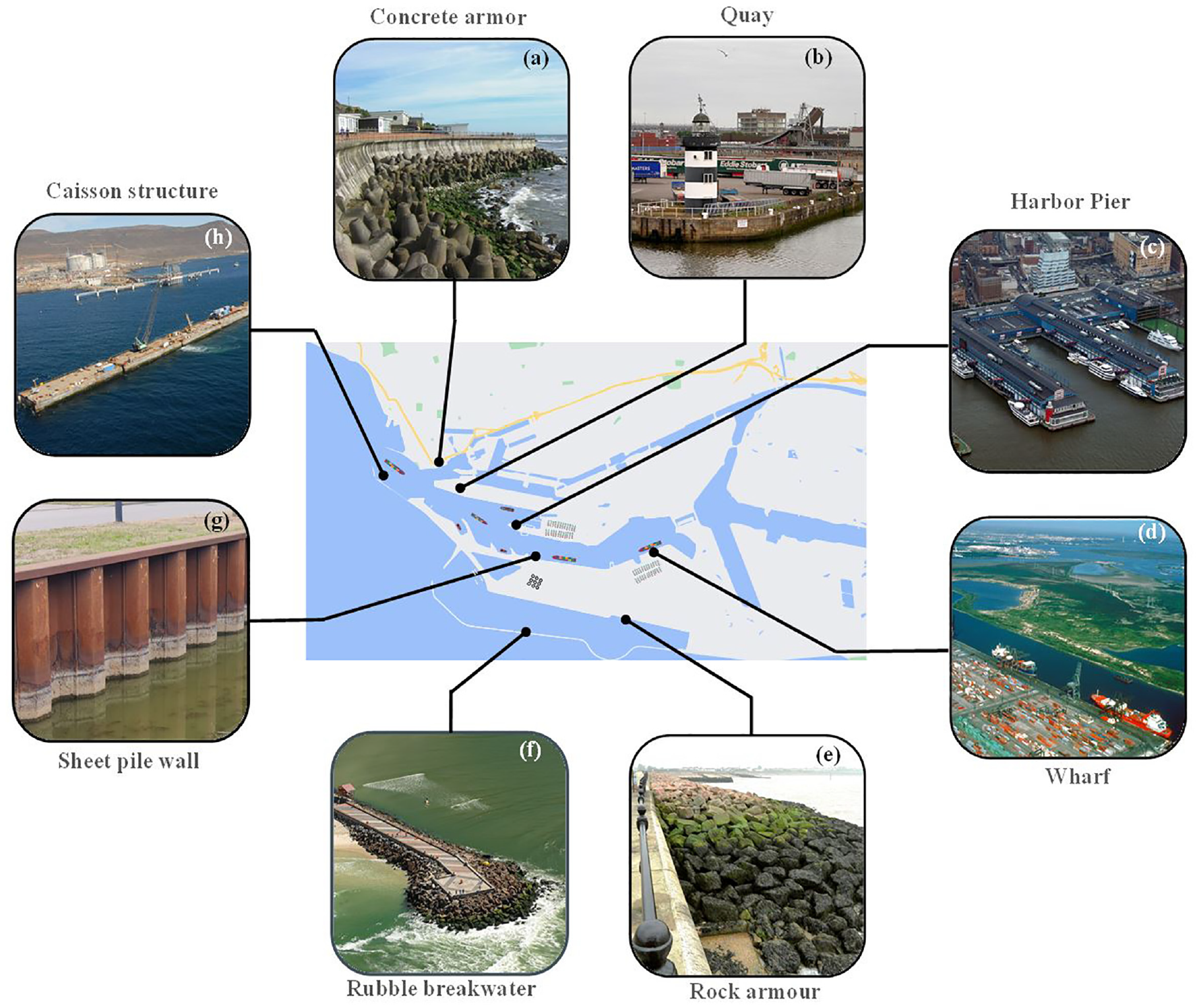
A schematic of various components of a seaport facility: (a) a tetrapod concrete armor, 155 (b) a quay wall in the Port of Dublin, 156 (c) harbor piers (Chelsea Piers, USA), 157 (d) a large wharf at the Port of Houston, USA, 158 (e) a rock armor revetment, 159 (f) a rubble breakwater, Barra da Tijuca Beach, Brazil, 160 (g) sheet pile wall, and (h) a caisson breakwater. 161
The main stressors responsible for the deterioration of seaport structures are scouring, sulfate attack, corrosion, wave action, and ship impacts. Global changes in foundation structures, such as uneven settlement, overturning, and sliding, can be observed on the deck surface by visible indications such as cracks and heaving. However, local changes in foundation structures, such as scouring at the foundation structure interface, require monitoring and regular observation to prevent a sudden collapse of the superstructure.
General port structures
In comparison to buildings and bridges, SHM of general port structures has not been much investigated. 162 Oftentimes, during port facility inspections, special investigations are required to identify stressors, post-extreme event damage assessment, and inconsistencies and flaws in prior designs. Such investigations help maintenance teams to have good insights for retrofitting measures and repairs. Inspection can aid identifying requirements of SHM systems for a port complex, which has concrete, steel, and geotechnical structures.
To monitor tilt or settlement of general port structures, conventional displacement measuring techniques, like contact sensors, have some technical limitations: (i) a contact sensor usually collects measurements at a single location, ideally, distributed measurements need to be collected of caissons of piers, and (ii) due to the presence of water some locations, for example on caissons, are difficult to access. For seaports, marine conditions portray challenges for conventional electrical sensors, as they develop thermal errors, corrosion, and sometimes short circuits. 163 Vision-based monitoring has demonstrated its feasibility, in inspecting 6-DOF displacements by measuring slope, deflection, and slip at multiple points. 164 The applications of vision-based monitoring in a port facility are not limited to monitoring the condition of port infrastructure but can be extended to monitor the berthing of ships. 165
Furthermore, the condition of concrete, steel, and geotechnical structures in port complexes can be assessed through vibrational parameters. However, one of the major issues in performing vibration-based SHM in general port structures is the change in the natural frequency of the structure with the fluctuation of the water level. 166 In such cases, the mass of the water up to the submerged portion is added to the self-weight of the structure, which decreases the natural frequency and increases the damping ratio.167,168 Hence, it becomes crucial to understand the vibrational behavior of the structure at different water levels, as it might affect the comparison of vibrational parameters for assessing the condition of the structure.
In the following sections, monitoring of the structural health of general port structures is discussed through a series of case studies. We separate these structures in two groups: structures parallel to the shore and structures extending out from the shore.
Structures parallel to the shore: Port wharves and quays
A wharf is a structure built along or at an angle to navigable waters where ships and barges dock to load or unload cargo and passengers. As shown in Figure 4(d), wharves generally consist of other structures such as cranes and warehouse buildings. For ports with soft soil, high piled wharves are commonly considered, in which the entire load on a wharf platform is supported by several pile foundations. A permanent tilt or settlement can be a critical measure of their condition.
Green et al. 169 found evidence of considerable deterioration of the wharf and piling at the Port-au-Prince seaport in Haiti, which had been reported in previous inspections but neglected, resulting in ground failure at the western end of the North wharf as a result of the 2010 Haiti earthquake. The earthquake caused sand boils and significant liquefaction, forcing the entire wharf to move 89 cm in a zone stretching inland 30 m from the post-shock shoreline. In an incident at Wroclaw, Poland, a 100 m long RC section of the wharf of the Odra river collapsed due to the fluctuation in water level. The investigations reported an un-noticed displacement of 15 cm of the structure toward the river, which became critical. 170 Marine wharves deteriorate quicker than other structures at the port facilities due to their demanding operating conditions. 171
Various sensors and sensing techniques have been used to monitor the structural health of wharves. Lecieux et al. 49 developed a measurement chain with various sensors to monitor the evolution of concrete in a wharf structure at Saint-Nazaire port, France. They installed resistivity sensors, chloride sensors, humidity and temperature probes, and FBG sensors for strain and temperature at the construction of the wharf and acquired the data for 1 year. The main aim of the study was to quantify the chloride effect, which is responsible for the corrosion of the reinforcement. They also discussed the malfunctioning of several sensors and provided critical insight into the shortcomings of contact-based sensing.
Nonetheless, due to their resistance to EM noise, damp conditions, and radio interference, FBG sensors are an excellent choice for marine environments. 172 In comparison to standard electrical sensors, FBG sensors are nonconductive and unaffected by the maritime environment, which makes them suitable for use in water for extended time. Liu et al. 173 used FBG sensors to monitor dynamic strain and obliquity angle in prestressed concrete piles during the construction of a high-piled wharf project in Tianjin Port, China. They measured the maximum compressive strain at the middle of a pile during pile driving and found that it was within the limits of ultimate compressive strain.
Some of the components of general port structures that can experience displacement extend over large distances, for example, the Port of Rotterdam maintains 80 km of quay walls in total. 18 Furthermore, sections of earth retaining quay walls along canals are at risk of collapsing.174,175 Quays along canals can run for several kilometers; thus, reconstruction or repair of long sections can be impractical due to limited resources. Efficient monitoring can assist in prioritizing repairs in such cases.
In 1999, the Port Authority of Genoa, Italy, used FOSs for monitoring possible disruptions of quay walls due to dredging activities. 176 They observed that sensors bonded to the outer surface of the quay blocks showed a lower response than those bonded near the pier root. FBG sensors have also been used as load cells for measuring ground anchor forces in quay walls. 177 They are suitable for long-term monitoring as they are stable in measuring loads over time. In another long-term monitoring case study, Yáñez-Godoy et al. 178 tracked quays from construction to 2 years of operation to develop an in-depth understanding of their in-service behavior. They instrumented VWSG on tie-rods between quay blocks and ESGs in a Wheatstone bridge fashion, to avoid recording flexure strains and measure only longitudinal strains in tie rods. In addition, they employed piezometers and tidal gauges to monitor fluctuations in the water level adjacent to the quay wall. The findings were crucial for performing a re-analysis of the quays in a scenario of future modifications. The nonlinear behavior of soil makes it difficult to establish a high confidence correlation between numerical and probability-based reliability assessments of quay walls. 179 In such cases, monitoring data can effectively improve the reliability models by taking account of several uncertainty parameters. Ichii et al. 180 proposed to monitor sheet pile quay walls through surface wave monitoring using geophones. The method was efficient in identifying the groundwater conditions but can be tedious and uneconomic in assessing longer sections.
In recent years, several attempts of using ROUV in the monitoring of quays have been made. ROUVs equipped with cameras and sensors are a preferable alternative to human divers. They eliminate the risk to human life. 181 Satellite-based monitoring of structure displacement using the scattering-based InSAR technique has shown promising results in measuring deformations of the structures along the quays.182,183 Calibration of the InSAR measurements with ground observations improves accuracy. In the near future, the technique has the potential to identify critical sections that require immediate intervention.
Structures extending out from the shore: Caissons and piers
Soil–structure interaction constitutes the most common source for damage to general port structures. 184 For caissons, slipping at the soil–structure interface has been reported as the primary damage.185,186 During the 1995 Hyogoken-Nambu earthquake at Kobe port, Japan, the caisson-type quay walls experienced an average displacement of 3 m toward the sea, as well as rotation and settlement in the soil. The seismically designed caisson-type quay walls resisted the strong ground motions. 187
Vibration-based monitoring has been thoroughly explored for condition monitoring of caissons employing various techniques, for example, harmony search method 188 and dynamic centrifuge tests. 189 Lee et al. 190 successfully attempted to use vibration-based SHM to detect local damage at the foundation level, such as scouring, which can lead to global damage such as tilting, shifting, and settlement due to wave actions. Later, Huynh et al. 191 proposed to measure changes in modal strain energy (MSE) for monitoring damage in interlocked multiple caisson structures, as shown in Figure 4(h) as an example. MSE, a damage index for accurately locating and quantifying structural damage is related to the second-order derivatives of the mode shapes for plate-like structures. 192 MSE is proven to be more sensitive to damage than mode shapes and natural frequencies. Huynh et al. 191 numerically simulated caisson units connected through shear keys and interacting with the foundation, recreating different damage scenarios. Based on the numerical results, they verified the feasibility of using MSE as a damage-sensitive parameter in the case of monitoring interconnected caissons.
Lee et al. 29 used laboratory-scale models to experimentally validate vibration-based monitoring of the harbor caissons at the foundation structure interface. They used accelerometers to obtain modal parameters for single caissons in non-submerged conditions and observed the parameters to be effective in monitoring damage caused by the removal of armor gravel. However, they noted the challenges to be overcome while using vibration monitoring in field conditions such as removal of the water-level effect on measurements and low sensitivity of mode shapes due to the presence of damage. These issues were previously raised by Yuan-Zhan et al. 193 in their numerical study. They found fluctuations in dynamic parameters of the caisson structure due to partially submerged conditions. They also observed, that as the water level rises, the natural frequency of the structure decreases, and the damping ratio increases. Therefore, it becomes mandatory to apply corrections to the recorded parameters, before using them for the comparison of damage detection.
The Oh-Ryuk-do breakwater in Busan, South Korea, was monitored using a wireless sensor system. 73 The parapet cap above the caissons was instrumented with wireless accelerometers on three different caisson units. The monitoring was performed using the natural excitation through waves and wind only, with no other forced excitations. Damage in the structure was analyzed using vibration-based methods involving a comparison of modal parameters and power-spectral density before and after the damaging episode. They proposed to define the reference state by comparing the relative motions of the instrumented caissons and also emphasized the importance of the direction of the accelerometer to acquire a strong response.
Recently, Bolourani et al. 184 numerically implemented static (dead load of the structure, live load, truckload) and dynamic (earthquake and vessel impact) loads on the caissons. They simulated damage as scouring of bedding sand layer and performed analyses considering both frequency and time-series features. In addition, they used principal component analysis (PCA) to reduce the dimensionality of the data, hence optimizing the online SHM. These investigations demonstrated the utility of vibration-based SHM approaches for monitoring the caisson foundations of breakwaters and harbors, particularly for damage that occurred at the level of soil–structure interaction.
The Port of Genoa, Italy, initiated a project to monitor harbor piers (an example shown in Figure 4(c)) using fiber-optic deformation sensors for planning maintenance and retrofitting operations of the port.84,85 A quay wall of a pier was instrumented with 72 fiber optic linear deformation sensors (10 m active length of each sensor) along different sections to monitor the distress caused by dredging activities. They observed temperature as a significant stressor causing displacement in the quay walls. However, due to the complexity of the joints between the blocks, the effect of dredging activities could not be established. The passive tendons supporting the large concrete blocks of the pier were further equipped with FBG sensors for measuring strains and temperature. The monitoring system was effective in correlating the effect of dredging activities on the stability of pier walls. Maintenance dredging is carried out regularly in port facilities and can inflict damage to the piles. 194 This often results in replacing the damaged piles. Monitoring strains and displacements in vulnerable piles can help ensure safe dredging and avoid any disagreements between the maintenance company and port authorities.
Coastal structures
In the context of seaports, the most relevant coastal structures are breakwaters and revetments. Breakwaters are sea-backed on both sides such that wave action is a dominant force in disturbing their stability. Revetments are similar structures, but land-backed. These types of structures are often constructed with interlocking rocks or concrete blocks. These blocks are prone to shifting and can generate major slides due to tsunamis and scouring. As protective structures, their monitoring and timely maintenance become critical to ensure the safety of the coastline they protect.
A rubble-type breakwater (see Figure 4(f)) consists of an inner core, outer protection (armor) layer, and sometimes a superstructure. The elements of armor tend to shift from their original location due to the long-wave action, exposing the core to waves. Some of the common modes of failure of a rubble-type breakwater are sliding of the superstructure, overtopping, toe instability, and excessive settlement of the entire structure. 195 Almazan et al. 196 measured the forces (accelerations and velocities) caused by waves during a storm on a breakwater and found them comparable to the impacts during the docking of vessels.
Campos et al. 197 reviewed the definition, parameterization, and measurement of damage in rubble mound breakwaters. They suggested that damage is characterized following a visual approach or a measuring approach, which is based on a 2D or 3D profile reconstruction. One of the challenges in monitoring an armored breakwater for displacements, settlements, damage, and losses in packing, has been choosing monitoring locations and their number. As the structure is not rigid and has hundreds of independent concrete/rock blocks interlinked to each other, placing sensors on each of them is not feasible.
In some of the earlier attempts, the breakwaters were monitored through conventional methods of visual inspection and line survey. However, documenting the visual observations for evaluating the present state of a section of the breakwater involves a potential for high errors. 198 Aerial photographic surveys using UAVs (as illustrated in Figure 5(b)) and underwater inspection are effective in identifying the breakages in individual core-loc (armor protection), still, the process is time-consuming and labor-intensive.199,200 Ferraz et al. 201 proposed image analysis to evaluate the stability of rubble-mound breakwater (indicated in Figure 4(f)) and successfully detected the displacement of rock blocks. The study was performed in a laboratory environment on a scaled physical model. Its application in the field conditions is very challenging. However, the approach was comparable to satellite imagery for monitoring, which is viable in the field environment.
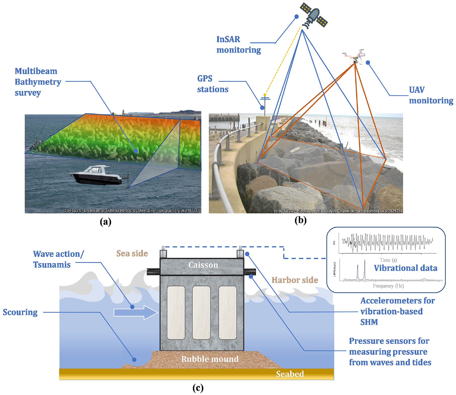
A conceptualization of monitoring techniques for breakwaters: (a) a multi-beam side scan sonar for bathymetry survey of concrete armor, (b) InSAR, GPS, and UAV-based monitoring of a rubble mound breakwater, (c) and accelerators and pressure sensors for monitoring caisson breakwaters.
In 2017, Natsuaki et al. 202 performed preliminary experiments for monitoring the movement of concrete armor used for coastal protection (as shown in Figure 4(b)) from the original position using InSAR (as shown in Figure 5(b)). The method uses SAR images from the ALOS-2 satellite, having amplitude and phase information in each pixel to generate interferograms of an area. The interferograms of an area at different times are compared to calculate the deformation in the direction of line-of-sight from the satellite. ALOS-2 can monitor the region once every 14 days which is the return period for a point in its orbit. The authors monitored the southern breakwater at the Nagata port, Japan, and observed a shift in the armors due to wave actions.
Another way of monitoring the degradation of rubble mound breakwaters is LiDAR-based remote sensing. Esposito et al. 203 demonstrated an approach for reconstructing 3D geometric models of the cube armored rubble mound breakwaters using incomplete LiDAR point clouds to perform their monitoring over time. The study featured constraints regarding the accuracy of models due to the limited view available from the scanning location. Apart from far-range monitoring, researchers have also effectively combined two close-range detection techniques in an integrated manner so that the limitations of one can be compensated by the advantages of the other. Saponaro et al. 204 demonstrated the use of a TLS and visual camera installed on a remotely piloted aircraft system for developing a dense 3D point cloud. However, the study was only a proof of concept and did not attempt to evaluate condition of a coastal protection system. In recent years, methods for monitoring breakwaters have been explored at a number of port locations. Remote sensing approaches, such as displacement measurement by InSAR monitoring, are feasible and effective in monitoring both rock and concrete rubble breakwaters.
Grosso et al. 128 monitored the reinforcement procedure of a century-old breakwater at the Port of Genoa, Italy, using GPS-based movement monitoring system (see Figure 5(b)). The system consisted of 10 GPS antennas installed on different sections of the breakwater and two reference antennas on firm stable ground. Furthermore, they compared the displacement results to an accessible data set using the PSI. The PSI has better accuracy (1–3 mm) in measuring displacement than GPS; however, its measurement interval is longer. After continuously monitoring for 4 years, a decrease in the vertical displacement of the breakwater with the progress in repair operations was observed. They proposed using both the satellite systems complementing each other, over the traditional surveying methods.
Pereira et al. 205 performed SHM of a breakwater in the Funchal Port, Portugal for 30 months using a hybrid approach. They identified multiple object points on the crest to be monitored for 3D displacements through the GNSS. The observations from the GNSS were correlated with acceleration amplitudes from the installed accelerometers. The system successfully provided insights on the structural stability of breakwater after impacts from dockings of cruise ships. However, the authors recommended further investigations due to an offset in the time domain between the GNSS observations and accelerometer values. They also recommended regular underwater video inspection for detecting any reduction in the slope of the breakwater foundations. 206
Multibeam sonar scanners are commonly used by inspection teams for marine scanning to conduct a high-quality asset mapping, as shown in Figure 5(a). However, sonar scanning is generally performed using a moving vessel and is considered an advanced form of inspection instead of a continuous monitoring system, which records slow progressive changes in breakwaters.
The gravity type caisson breakwater resists the wave action using its own weight. The caisson-type breakwaters were mostly monitored with vibration-based techniques. Lee et al. 74 performed OMA on the Oryuk-do breakwater at the Port of Busan, Korea using piezoelectric accelerometers. The aim of the study was to analyze the structural stability of breakwater against overturning, settlement, and sliding. They acquired the in situ dynamic characteristics under ambient wave excitations. The natural frequency of the caisson increased as the water level lowered; however, the modal damping and mode shape did not indicate any correlations. The study recommended further investigation into the mode shapes of different caissons in the array.
Recently, Fu et al. 88 proposed using HLPFGs for long-term durability monitoring of coastal structures. The system was capable of measuring strain and torsion in the sea-sand concrete structure under seawater. However, the study was conducted in a laboratory environment and requires field validation.
Newly built breakwaters are susceptible to scour which leads to a sinking of the structure into the seabed. Perez et al. 207 implemented a novel methodology of observing the sinking of concrete modules with installed pressure sensors (see Figure 5(c)). They observed a continuous sinking even after backfilling due to the wave structure interaction as the modules were placed close to the breaking zone. In addition, they have presented a brief comparison of case studies on the sinking of submerged breakwaters from all over the world. Scour around the structure will be a much lesser issue with the recently introduced, nature-based concept of a Sandbar Breakwater, being constructed in 2018 in Lekki, Nigeria. 208 This type of breakwater utilizes the natural process of sand accumulation (caused by interruption of the longshore sediment drift) to build out an initial breakwater design consisting of a combination of dredged sand and some rock material, hence requiring less rock volume. 208 As a minimum geometry of the sandbar breakwater must be maintained, this requires regular monitoring of the coastline position, bathymetry, and topography.
Summary
Damage developing in port structures mostly arises from soil–structure interaction. This interaction results in tilt and settlement of structures, which can ultimately lead to the collapse of these structures. Regarding damage to coastal structures associated with seaports, displacement of blocks by waves, and scour-related sinking of the structure into the sea bed play a large role. The condition of concrete, steel, and geotechnical structures in ports can be assessed through a range of sensors, including for example resistivity sensors, chloride sensors, humidity and temperature probes, and FBG sensors. For seaports, marine conditions portray challenges in employing conventional electrical sensors for SHM. Under those conditions, advanced sensing technologies like FBG sensors, are proved to be more successful than electrical sensors. The condition of concrete, steel, and geotechnical structures can also be assessed through vibrational parameters. However, one of the major issues in performing vibration-based SHM in port structures is the change in the natural frequency of the structure with the fluctuation of the water level.
To monitor displacement of spatially extended structures, such as quay walls and breakwaters, satellite-based techniques are found to be promising for continuous monitoring. In the near future, the technique has the potential to identify critical sections of quay walls that require immediate intervention. Continuous monitoring of the submerged parts of these spatially extended port structures is still a challenge.
Waterway protection structures
Navigation waterways (also channels) may require regulations through river training and stabilization works to maintain sufficient width, depth, and gradient of water with controlled currents to be considered navigable. 209 These regulations are met by building (artificial) water protection structures such as dikes, groynes, revetments, quays, and locks along waterways. Apart from regulating the flow of a channel, water protection structures (i.e., dikes, groynes, revetments) also safeguard residential areas from floods and provide bank protection from the erosion and recession, which is also caused by large ships generate long recurring primary waves. This section discusses studies on SHM of groynes, revetments, and dikes.
Groynes and river banks
Groynes (or groins) are geotechnical structures constructed in rivers to deflect the flow away from critical zones. 210 They are built up of arranged stones, gravels, or soil, protruding toward the width of the river from its bank. They are subjected to high currents during floods and turbulent ship wakes. Pires et al. 211 attempted to monitor rubble groynes along the coastal shoreline using geographical information system (GIS) tools. They set up a geo-referenced database for groynes using ground-based geotechnical data and aerial photographs, and calculated the area of damaged sections. The study emphasized the importance of monitoring for efficient maintenance measures. Umar et al. 212 extracted coastline vectors from satellite images to monitor shoreline erosion of the Padang beach, Indonesia. They reported that remote sensing methods provide reasonable accuracy for monitoring inland and coastal regions. The technique was able to monitor the improvements in the shoreline after the construction of groynes and jetties.
TLSs and LiDAR are widely used to create high-resolution 3D digital elevation models of river and coastal banks to monitor spatial and temporal morphological changes.107,127 Tschirschwitz et al. 213 monitored groynes on a navigation channel from the Elbe to the Port of Hamburg, Germany. There were cases of breakthroughs between connections between revetments and groynes in the channel. They were caused by long and periodic wave loads induced from large vessels. The authors monitored changes in the geometry of groynes using a TLC for two years. They reported the following challenges: (i) maintaining power in remote location, (ii) dealing with large data, (iii) managing a large number of outliers in the measurements, and (iv) and analyzing the collected data. They also reported the highest erosion in one-third of the length of groynes toward the river. They further proposed to extend the study to correlate the deterioration with passages of vessels. A TLS can generate a four times denser 3D point cloud than a drone mapping, but it is three times slower in acquiring data than a drone. 214 A UAV mounted with a LiDAR can generate a high surface density model comparable to a ground TLS, but it can be a costly option. 215 The armor layer porosity and packing density of rubble mound groynes having regular size units (shape factor of 60%–80%) can be monitored efficiently utilizing UAV-based remote sensing.
CV-based systems have also been used for monitoring shorelines and sediment nourishment.216–219 Uunk et al. 220 employed an automated approach for an intertidal bathymetry and conducted a long-term monitoring program to study storm impact, seasonal changes, and other parameters on the shoreline. Later, Santos et al. 221 showed the capability of a CV-based system in quantifying the changes in shoreline protected with groynes. The deposition of sediments or erosion is monitored against a shoreline extracted from time-averaged images. 222 The height of the monitoring station is a crucial parameter and is selected considering the coverage area and image resolution. 216 However, a minor camera movement in camera position due to thermal or mechanical reasons can cause significant georectification issues, which need to be corrected before comparing the recorded images.223,224 Even after being firmly mounted, optical cameras are subject to movements due to the solar heating and tiny, periodic refocusing of the camera. 225 Cameras have also been used as space-time image velocimeters to measure flow velocity. 226 Aelbrecht et al. 227 monitored a 1/40 scaled model of a riverbank and groynes in the laboratory environment. They estimated the volumetric deposition or erosion of sediments using 3D laser scanning. The study was extended to examine the long-term monitoring of morphological traits. It is evident from the literature that only noncontact/remote sensing techniques are being used to monitor groynes and river banks.
Dikes
A dike is an earthen flood defense structure built parallel to a flowing water body, such as a canal, river, or along the sea coast, to protect the adjacent area from flooding. In some rivers, dikes are built to maintain the required depth for navigation. However, the depth of the river is primarily maintained by dredging as it is considered 10-fold more economic than structural measures. 228 Still, the failure of dikes during floods, often called a breach, can trigger a major catastrophe and can disrupt navigation. Typically, dike monitoring involves patrolling and expert visual inspections, which are neither economical nor consistently effective in identifying problems. 81 Even with expert observations, it can be challenging to detect volumetric changes or variations in the slope of a dike. Considering this, a well-designed SHM system could be a viable alternative. Figure 6 depicts the most commonly employed monitoring techniques for dikes. The SHM of flood defense structures aids in assessing reliability and requirements for reinforcement. 229 Monitoring soil parameters such as pore water pressure, density, and moisture, or observing settlement in the structure provide helpful information for assessing the stability of earthwork structures.
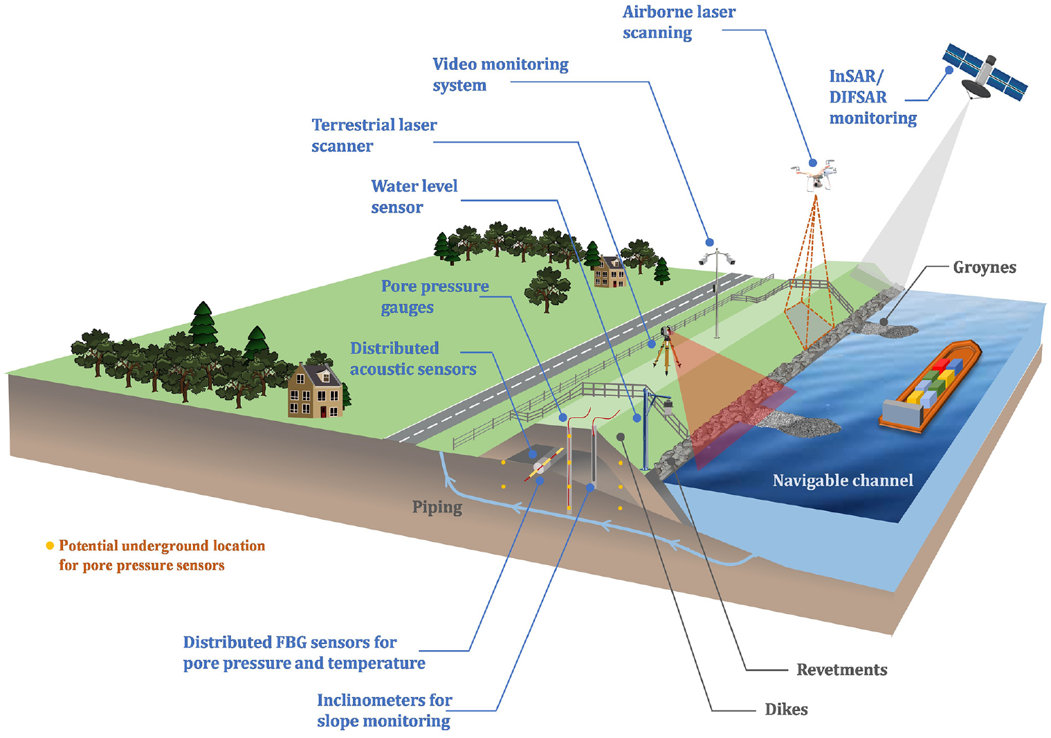
A conceptual overview of contact and remote sensing techniques for monitoring dikes, groynes, and revetments protecting waterways.
In 2007, the IJkdijk project was initiated in the Netherlands for the development and testing of early warning dike monitoring technologies on a full-scale model dike. 110 Most of the studies discussed in this section on SHM of dikes have been tested at this site. In 2011, the dike was declared unsafe in a safety assessment. 230 Dutch authorities then decided to develop the Ommelanderzeedijk as a living laboratory. The monitoring saved 40% of maintenance costs. The study concluded that SHM is a crucial component of the life cycle management of dikes.
During floods, a completely distributed sensing system that detects internal seepages or soil movement in river embankments can provide essential data and issue early warnings. Several attempts have been made to monitor the internal seepage in dikes by (i) measuring the electrical resistance between two points in the soil, 231 (ii) using GPR measurements, 232 (iii) performing passive seismic interferometry with geophones, 233 and (iv) collecting temperature measurements with distributed fiber sensors.234,235 Clemens et al. 236 proposed measuring density and volume changes due to the contact erosion in dikes using the impedance spectroscopy. The technique employs capacitive sensors for measuring the dielectric properties of the surrounding soil. However, the study was a proof of concept conducted in a laboratory environment and has yet to be verified for practicability in the field conditions. Krzhizhanovskaya et al. 237 proposed a prototype of an AI-based early warning system for urban floods utilizing the data obtained from sensors in flood defenses. The technique could analyze the stability of a dike and forecasting its failure. It was developed within the UrbanFlood EU FP7 project, in which the extent and feasibility of monitoring dikes and floods remotely were investigated. 238 The AI-based system analyzes the probability of a dike failure and simulates the consequences of the dike breach on the surrounding region using a network of sensors. 237 The data are fed into an indigenously developed Virtual Dike software to train an AI module for predicting its response due to instabilities. The AI module uses a data-driven approach for the real-time condition assessment. 239
The seepage at the soil–concrete joint contributes to a failure of a dike, especially when a sluice or culvert passes through it. 240 Thus, the erosion at contact zones caused by seepage is minimized to preserve the stability of flood protection dikes. In such cases, monitoring the internal temperature of a dike to detect seepage beneath the ground level has been proven to be beneficial. Su et al. 241 experimentally monitored the seepage at soil–concrete interaction using an optical fiber-based DTS. FBG sensors integrated with geotextiles have been tested for measuring strains in dikes. 87 Attempts have been made to identify the progress of piping in dikes by acquiring acoustic emissions, at the IJkdijk field-lab 242 and in small-scale laboratory tests. 183 However, the fact that granular media is poor for the propagation of high-frequency AE signals limits its applicability on full-scale structures.
Several modules of multi-parameter sensor networks are commercially available for monitoring soil stability in dikes. 77 They generally comprise inclinometers, temperature sensors, and piezo sensors. The data are analyzed for anomalies that aid in detecting damage at its onset, allowing for a prompt intervention to avoid its further propagation. Pyayt et al. 243 developed an anomaly detection technique that uses time–frequency feature extraction from wavelet analysis and phase shift measurements on data from multi-sensor modules. The modules were installed in the Boston dike (UK) and the Rhine dike (Germany) under the UrbanFlood project for an online early warning system. The study emphasized the importance of measuring pore water pressure, groundwater flow, and deformations, especially during spring tides. The pore water pressure can have short- and long-term effects due to changes in the water level. 81 It is commonly considered a significant factor in the failure of slopes. Bennett et al. 244 developed a shape acceleration array by coupling an in-place inclinometer with accelerometers. The array was able to measure in situ accelerations and deformations up to a hundred meter depth. The system was tested at the IJkdijk dike testing site and successfully identified real-time status of the dike during a stability test. One of the primary concerns with wired monitoring is that data from networks of wired in situ sensors are acquired through parallel configurations between sensors and data acquisition units. This leads to the interference between the wires and the distortion of recorded measurements. Thus, taking measurements in a parallel-serial mode can be suitable for monitoring linear dikes. 245
The feasibility of geophysical and remote sensing techniques has also been studied for dike SHM. ERT is one of the most commonly used geophysical methods for assessing the geotechnical condition of earthen dikes. 89 However, it has to be performed at the site, which can be labor-intensive; thus, it is used only at critical locations. Tresoldi et al. 246 developed a prototype of ERT for shallow depth monitoring that can be permanently installed and requires less current (200 mA) to monitor an embankment dike at a single cross-section. They reported the system as being ineffective in distinguishing rainfalls from changing water levels in canals.
The length of dikes can be up to tens of kilometers, making it a practical challenge to monitor them using contact sensors. For example, 17,000 km of dikes are found in the Dutch flood defense systems. Only a few stretches are continuously monitored using in situ sensors.247,248 The rest are inspected visually. In such circumstances, InSAR-based 249 remote monitoring has demonstrated strong capabilities measuring displacements at a high precision over a wide swath of coverage. 250 The technique is efficient monitoring internal structural changes in dikes that lead to settlement or displacement at their outer surfaces. Over the last two decades, LiDAR and InSAR have been examined for their ability to monitor dike deformations and slides caused by seepage or other factors. 251 Recently, a combination of both methods has been used to estimate the rate of land subsidence for a 10 km long dike. 252 The method was able to determine the additional soil required to counteract the effect of subsidence for the next 50 years. Mechanisms of dike failure, and resulting vertical and horizontal movements that can be monitored remotely using radar interferometry are also discussed in Özer et al. 249
Remote monitoring becomes crucial when a long stretch of a dike needs immediate monitoring, particularly during (or immediately after) floods or storms. Antoine et al. 253 introduced the integration of multiple remote sensors (LiDAR, near-infrared and optical cameras, and a thermal infrared camera) on a UAV to monitor the erosion of French dikes in conditions when it is unsafe for experts to carry out visual inspections. Cundill et al. 251 have discussed most of the remote monitoring techniques for dike monitoring. They further compared visible, thermal, and multi-spectral remote sensing data with ground measurements from soil moisture sensors, and observed soil moisture and grass cover quality as important parameters for monitoring grass-covered dikes.
Summary
Water protection structures are visually inspected and assessed based on predefined metrics and rubrics. 254 Visual inspections are cumbersome and tedious due to the vast expanse of these prolonged structures, while advanced sensor technologies offer monitoring these structures remotely, and with good and reliable results. With thousands of kilometers of dikes and river protections, and countless groynes already constructed, remote sensing will continue to play an important role in monitoring and assessing them, whereas a thorough real-time monitoring with contact sensors will be limited to relatively critical locations. Satellite-based monitoring is appropriate for measuring deformations and interior seepages on a regular basis. For urgent inspections, UAVs equipped with monitoring devices are the best option.
Navigation locks
Navigation lock facilitate navigating vessels to travel across two (or more) water stretches at different levels. They can be built along the width of a canal or constructed with a dam on wide rivers. An inland navigation route can have multiple navigation locks throughout a river span. A lock complex consists of a large, usually concrete chamber and two movable gates at both ends that close the chamber, allowing the water level to be raised or lowered with ships/barges inside. The water level in the chamber is controlled by filling and emptying valves in the lock culvert. The main structures are a lock chamber, where the vessel stays during the raising/lowering of water, and two hydraulic gates (one upstream and one downstream), which control the flow of water in the chamber. Gates are the most important and also the weakest components of a navigation lock complex. Odds of faults of movable elements in lock gates, due to wear and tear, are high. Figure 7 illustrates damage that might occur in a lock complex resulting in its temporary closure. In 2007, the Southern gate of the Meuse lock complex broke off from the hoisting chains causing a significant threat to navigating vessels. 255 The major causes of distress in lock gates include fatigue cracking formed at welded connections, pintle cracking, out-of-plane distortion/buckling, reduction in prestressing, shear cracking of pintle sockets, and fatigue failure of diagonals.256–258 The malfunction of locks is the primary source of closures and downtime on inland navigation waterways.31,259
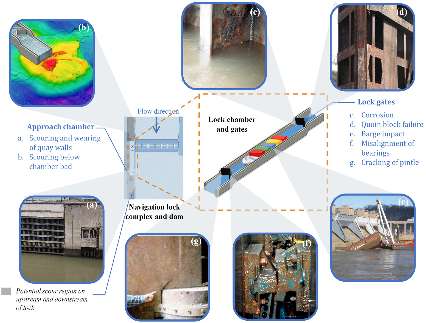
Common damages in navigation lock complexes: (a) scouring and wearing of quay walls of lock chamber, (b) scouring below the chamber bed, (c) corrosion of the navigation lock, 25 (d) failure of the quoin block, 25 (e) barge impact, 25 (f) misalignment of miter bearings, 260 and (g) cracking of the pintle. 258
The primary way of monitoring lock gates is a visual inspection. Even though it is time-consuming and labor-intensive, it is still considered one of the best methods. As gates are typically immersed in turbid water, visual inspections require complete closure of the facility and dewatering the lock chamber. The complex design of gates and their submergence in water makes visual inspections expensive and less efficient in detecting damage. Dewatering is done seldom. After operating for 20 years, the David D. Terry lock (USA) was completely dewatered for an inspection and repair of erosion damage. 261 Its dewatering disrupted the transportation of thousands of tons of goods. One of the earliest attempts in visual inspection-based observations for characterizing the level of damage in hydraulic lock gates was done by Greimann and co-workers. 262 Based on their experience, they assigned distress codes and weights to different types of damage for calculating condition indices. However, the study was a visual inspection-based decision-making tool rather than an SHM system. Visual inspections provide crucial information for lifetime reliability analysis and recommend repair strategies. 263 For example, Dang et al. 264 optimized visual inspections for the fatigue assessment of welded joints by computing stresses from fluctuating water levels and the number of lockages.
Ships enter and exit the lock chamber through approach channels, which are reinforced concrete slabs with two side walls, as illustrated in Figure 7(b). Navigation locks are not immune to the devastation caused by the scouring of channel bed that supports the entire load of the structure. During operations of a lock, the turbulence created by ship thrusters (while entering, existing, and waiting for the water to raise/drop) aggravates scouring below approach channels and side quays. In comparison to bridges, the probable scour locations in navigation locks are less predictable due to the multiple stressors involved, such as the presence of heavy propelling ships, seasonal floods, and turbulence caused by filling and draining of the lock chamber. In 2011, the Lock and Dam 25 on the upper Mississippi River (USA) experienced severe scouring on its downstream, reaching a depth of over 13.7 m. 265 The downstream floor slab, which functions as a lock chamber floor, partially failed due to material loss along the I-wall. It was perceived as a threat to the global stability of the structure. The floor was repaired for $5.1 million and the lock returned to its regular operation after 1 years. In a similar incident at the New Savannah Bluff Lock and Dam (USA), the inspection team indicated continuous deterioration under the floor of the lock wall resulting in a 15 m deep scour hole adjacent to the sheet piles. 266 The USACE carried out emergency repairs to avoid instability and to reduce risks of its collapse during the flood season. During an annual inspection of the world famous Panama Canal locks (Panama) in 2014, it was discovered that the Gatun lock had eroded from scouring for more than 6 m beneath the 2.1 m thick concrete lock approach slab and almost completely under foundations of separating walls. 267 The stability of the structure was perceived to be compromised and hence prompt actions were taken for its repair.
The majority of the above examples are from the North American region, however, due to the changing weather patterns, networks of inland waterways in Europe are vulnerable to such incidents. A large number of important locks in Europe lacks scour protection measures. The current practices followed in the field for identifying scour are hydrographic surveys and underwater inspection by divers. 268 Early detection of scouring through continuous monitoring could be a solution to prevent emergency closure and financial loss to the asset owners. Besides scouring, reinforced concrete structures are visually inspected, and NDT tests such as chloride content analysis, depth of concrete carbonation, and steel corrosion rate, are used to classify conditions of concrete for monitoring its degradation. 269 This section focuses on current techniques for the condition monitoring of lock gates. SHM of lock gates is categorized into local and global monitoring approaches.
Lock gates
Navigation lock gates can be classified based on the hydraulic load transfer mechanism. The three most prevalent types are (a) miter gates, (b) vertical lift gates, and (c) rolling gates. In miter gates, the load is transferred by both the bending moment and axial load, whereas in the other two types of gates, the load is transferred through the bending moment. Miter gates are more widely used than other types of gates. Figure 8 illustrates the location of miter gates in lock and dam complexes and their structural components. An inland navigation system consists of numerous static and moving components, which are prone to human-induced and natural stressors such as corrosion, hydraulic loading, and environmental variance. The concept of automating the monitoring process of miter gates is not new. It was first discussed by Commander et al. 270 due to its economic importance and criticality to the lock complex. They reported a huge requirement of interpretation and evaluation of the recorded results before condition assessment can be automated.
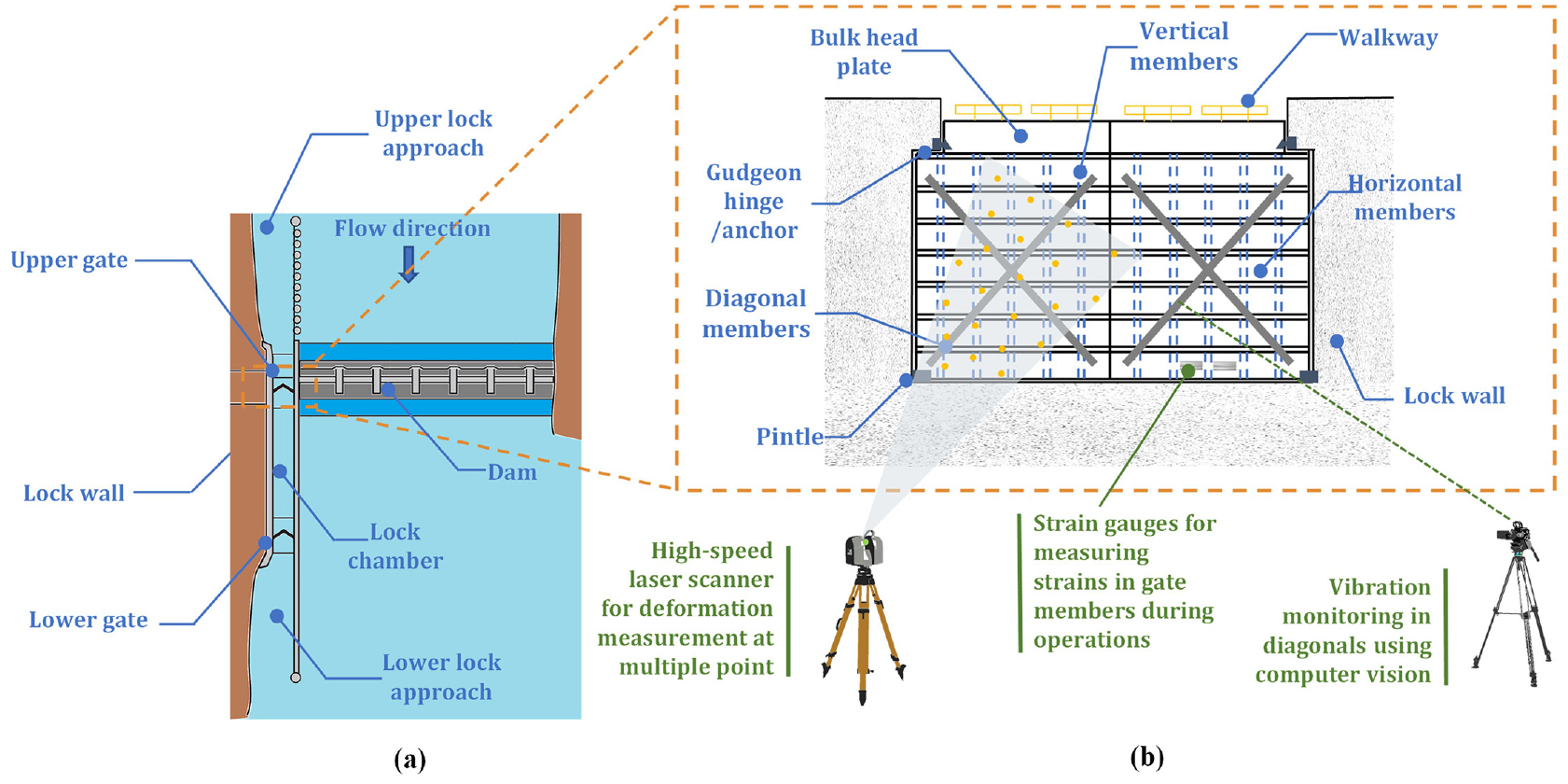
(a) Layout of a typical lock and dam complex 271 and (b) conceptualization of different SHM techniques used in monitoring lock gates.
Local monitoring
Underwater inspections of gates and other submerged structures involve skilled divers accessing underwater components and assessing their condition. Such assessments are hazardous and not consistently effective due to the poor visibility. The gates are always partially submerged in turbid water which hinders underwater visual inspections even with visual cameras for identifying defects at the local level, for example, dents due to barge impacts and corrosion. Acoustic cameras, which are based on high-frequency sonars, are quite efficient in scanning and imaging features of structures submerged in turbid water. 118 Sonars can be mounted on manually or remotely operated boats to record detailed scans in deep waters. The sonar scanning is effective in identifying cracks in concrete, biological growth, deposition of sediments and debris, and scouring exposed steel and timber piles.
The data gathered from inspections are also used in prediction models to detect issues in operations of gates. Riveros and Arrendondo 25 proposed a Markov chain model to predict the deterioration of gates. Prediction models operate on two fundamental assumptions: (1) the deterioration of the structure is continuous (2) and the condition of the structure can be characterized by a limited number of states. The first assumption does not consider damage due to an extreme/unusual incident. In contrast, the second assumption has an issue with recognizing the state of the structure under a given categorization, which requires detailed observations. In general, a structure can have an infinite number of health states, and assigning the present condition to any of them becomes challenging. 272 The Markov chain model can predict the deterioration of hydraulic steel structures and can be made efficient by updating and recalibrating it with new data from condition assessments.
Inspections can suggest monitoring parameters, which can help to understand undergoing issues and, as a result, determine the plan of required repairs. The inspection crew at Chickamauga Lock and Dam (USA) discovered alkali-aggregate reaction (AAR) in the concrete. AAR is a chemical reaction between the cement and the aggregate that causes “concrete growth.” The AAR expansion of the concrete caused the misalignment of the lock miter gates and damage to the miter gate pintles and anchorages. The inspection crew carried out a structural analysis to determine the remaining service life of the miter gate anchorages. 66 They installed growth meters and extensometers, and observed a linear growth in strains at the location of installation on the anchors. The data also confirmed the previous survey measurements and predicted the expansion of concrete. It is evident from the case studies that visual inspections are the most commonly practiced methods of observing local level damage. It is not always feasible to attach sensors to monitor local-level defects, unless it is at a critical location on the structure and its malfunction can jeopardize the functionality of the gates. In a case study of the Mississippi river lock and dam, the gate was instrumented with strain sensors around an observed crack. The leaf developed excessive shear deformation, resulting in high tensile stresses induced by vertical loadings. 273 Such observations would unlikely be detected in visual inspections alone. Also, local-level damage may reflect in the global response of the structure. In that case, monitoring gates at the global level is an efficient option in terms of resources and analysis.
Global monitoring
One of the contributing stressors to the deterioration of navigation gates is collisions with passing vessels, which mainly result from human errors, strong winds, inability in slowing down vessels, and operational or mechanical failures at the lock facility. 274 Collision may inflict local damage as well as deform the gate at a global level, as the energy of a collision is expected to dissipate through the global bending of the gate. 275 It can cause loss of water tightness due to the change in the shape, and loss of operability and overall stability of the gate. In steel hydraulic gates, damage due to cracks and corrosion can cause the loss of stiffness in structural members. As a result, strain measurements in these components serve as warning signs of damage. In 1994, Commander et al. 270 reported damage detection in miter gates using visual inspection, numerical studies, and field measurements. In one of the studies, they installed 60 SGs on a leaf of a miter gate to measure strains during operational loads. They observed an inoperative seal between the gate and the bottom sill as the net hydraulic pressure was acting in the downstream direction. The observations were utilized to improve the design of the miter gates.
In some cases, quoins of gates become out of plumb with the wall of the lock creating a space between them. This space redistributes the hydraulic load which generates stresses at the other parts of the gates. Eick et al. 31 attempted to automate the monitoring of gates for detecting such redistribution of stresses, resulting from gaps between gate-to-wall interfaces, using SGs in a full-scale structure. They proposed using change of strain as a damage indicator instead of strain-time analysis and used PCA to reduce data dimensionality. The proposed method was successfully verified on a numerical model by introducing two gaps. Strain data have been interpreted to detect gaps in the quoin blocks and to learn about damage features using multi-layer artificial neural network, 276 deep Bayesian neural network (BNN) 79 , and variational BNN. 277 These techniques are more computationally efficient than the inverse FE analysis for mapping the gaps in the structure. The information from physics-based simulations and damage features can be used to prognose the failure of in miter gates and optimize maintenance tasks. 278 Vega et al. 279 proposed a general framework to integrate abstract data from visual inspections and strain data to study advancements in the gaps of quoin blocks. Smith et al. 66 placed 30 ESG on anchorage channels to find the axial force and bending moment in the linkage while operating the gates. These characteristics were helpful to validate a FE model built for studying effects of crack repairs by adding reinforcement plates.
Kutterer and Hesse 280 used a high-speed laser scanner for monitoring deformations of a gate due to exerted hydraulic loads from changing the water level (illustrated in Figure 8(b)). The data were acquired at 500,000 measurements/second and was analyzed using PCA to find interrelations between multiple data sets. The affected region due to deformations was detected. Binczyk et al. 260 deployed a laser scanner to perform modal analysis of a miter gate to identify the sources of excess vibrations during operations of the lock. They adopted a comparative methodology using dynamic measurements from the laser scanner, surveying, and numerical study. The authors concluded that laser scanning performed faster than tachymeter measurements in assessing structural displacements, but its accuracy was insufficient due to the subtraction of coordinates from two different point clouds.
Recent developments show the feasibility of CV-based monitoring of lock gates. Eick et al. 137 presented a proof of concept study by applying a CV-based technique using Lucas–Kanade optical flow for monitoring tension in diagonal members of a miter gate. The diagonal members are responsible to resist the torsional deflection of the gate against their weight. They recommended (i) further investigations to completely implement the vibration-based method as a tool for monitoring tension in members using CV-based measurement and (ii) and evaluating the effect of change in boundary conditions due to partial submergence of the structure as the water substantially influences the vibrational frequency and damping of the structure. Later, Eick et al. 76 monitored the unequal hoisting of tainter gates. They used preinstalled SGs and tiltmeters under the SMART initiative by USACE. However, the data were not sufficiently assertive in observing unequal hoisting. Furthermore, they used accelerometers to monitor tension in the hoisting cables, which lift and lower the gates. The approach was effective in detecting uneven hoisting. The use of accelerometers for acquiring acoustic data for assessing the linkage performance of reverse tainter valves has also been examined, but the research is still at its early stage. 75 The SMART Gate project is implemented at six sites of locks and dams. Each lock gate is installed with up to 250 sensors for monitoring (i) strains, loads, tilts, and temperatures on gates and (ii) and water levels.31,281 The system can also detect minor impacts of barges from accelerometer measurements. 47 The collected data is analyzed manually; its automation is under development. The high-dimensional data are processed using Bayesian and Gaussian approaches, and a precise FE model is employed to determine the damage location and cause. 282 The system can also issue warnings regarding the performance of degrading gates and excessive loadings.
Summary
The majority of monitoring case studies are on miter gates, that is, the most common type of lock gates. High-speed laser scanners and CV-based techniques are effective in condition assessment, but contact sensors (e.g., SGs) offer robustness and reliability for continuous monitoring of gates. Measuring strains and modal parameters can aid identifying locally affected areas, and the data can be utilized to update FE models and understand the severity of damage. Apart from the damage in gates, scouring of lock approaches is a significant concern that requires constant monitoring. While scouring beneath approaches to a lock has been reported in numerous cases, there is presently no significant study available on the subject in the literature.
Visual inspections are not effective in detecting incipient damage and misalignments in the structure. This sometimes results in the emergency closure of the entire facility due to a sudden breakdown. When dewatering is not possible, the inspection is conducted by underwater divers who are proficient in inspecting underwater facilities. Even though visual inspections face challenges, they are always considered invaluable by maintenance engineers due to their simplicity and adaptability.
Accessory structures
In an inland waterway network, some structures are constructed to perform specific functions making navigation possible and safeguarding the waterway from floods. This review shows surge barriers, navigable aqueducts, and ship lifts are denoted as accessory structures. Such structures are not widely available compared to structures such as dams and locks; thus, the literature involving their SHM is also limited. This section discusses SHM case studies of these accessory structures. These structures are sometimes also considered of national importance. Hence, a proper SHM system is required to keep them functional.
Storm surge barriers
Surge (or flood) barriers are structures, generally, constructed at mouths of rivers and tidal inlets to prevent storm surges or tides from flooding protected areas and damaging other constructions along the river. These structures safeguard ports and coastal cities from flooding, when sea levels rise. Around the North Sea coast, the Environment Agency (UK) and the Ministry of Infrastructure and Water Management (Netherlands) operate and maintain 16 storm surge barriers. Some of the famous examples are Oosterscheldekering part of Delta works (Netherlands), Maeslantkering on the New Waterway, which is the artificial mouth of river Rhine (Rotterdam, the Netherlands), the Thames Barrier on the River Thames (London, the UK), and the Navigation Pass S-1 of St. Petersburg Dam at the mouth of the River Neva (St. Petersburg, Russia). Movable surge barriers which are built on navigable waterways have a mechanism to allow continuous navigation across them. In storm surges, they can close the route, thus stopping the flow of water. Such structures are designed for extreme floods, for example, with a probability of occurring once in 4000 years. 283
As a result of frequent storms and rising sea levels, many surge barriers are closed more frequently than anticipated. This might negatively impact their integrity, operation, and design lifespan. Surge barriers are tested for their mechanical functioning through routine drills one or twice a month. The Maeslant Barrier (Maeslantkering), a movable surge barrier located on the New Waterway that protects the city and the Port of Rotterdam from storm surges. The barrier was designed to protect from Rotterdam from storms once every 10 years, but as the sea level rises, the barrier is closed frequently. The likelihood of a failure of closing the barrier increases from 1/1000 to 1/25 per year. 284 Apart from that, ground subsidence may result in a further reduction in the height of surge barriers, thereby increasing the hydraulic loads in floods. In accordance to the Dutch Water Act, flood defenses have to be assessed for statutory safety requirements on a regular basis. 285 In 2007 during the first major maintenance, the hydraulic pumps were found to be in poorer condition than expected, even with limited use since 1997. Later, the Maeslantkering was equipped with a sensor system for monitoring the hydraulic system and stresses in several structural components (e.g., the push–pull bar joining the drive train). 288 The data from the sensors are collected and analyzed every 3 months and after each yearly test, in which the barrier is closed to ensure its functionality. The second major overhaul cycle, which was due after 10 years, was safely postponed using this strategy, thus saving a significant cost.
Another example is the Thames Barrier (see Figure 9), which operates since 1982. Its design life is 90 years. It was designed for a storm surge with a return period of 1 in 1000 years. 289 Until 2014, the barrier was closed already 48 times, which is comparable to its combined closure (apart from monthly maintenance) over its entire design lifespan. 35
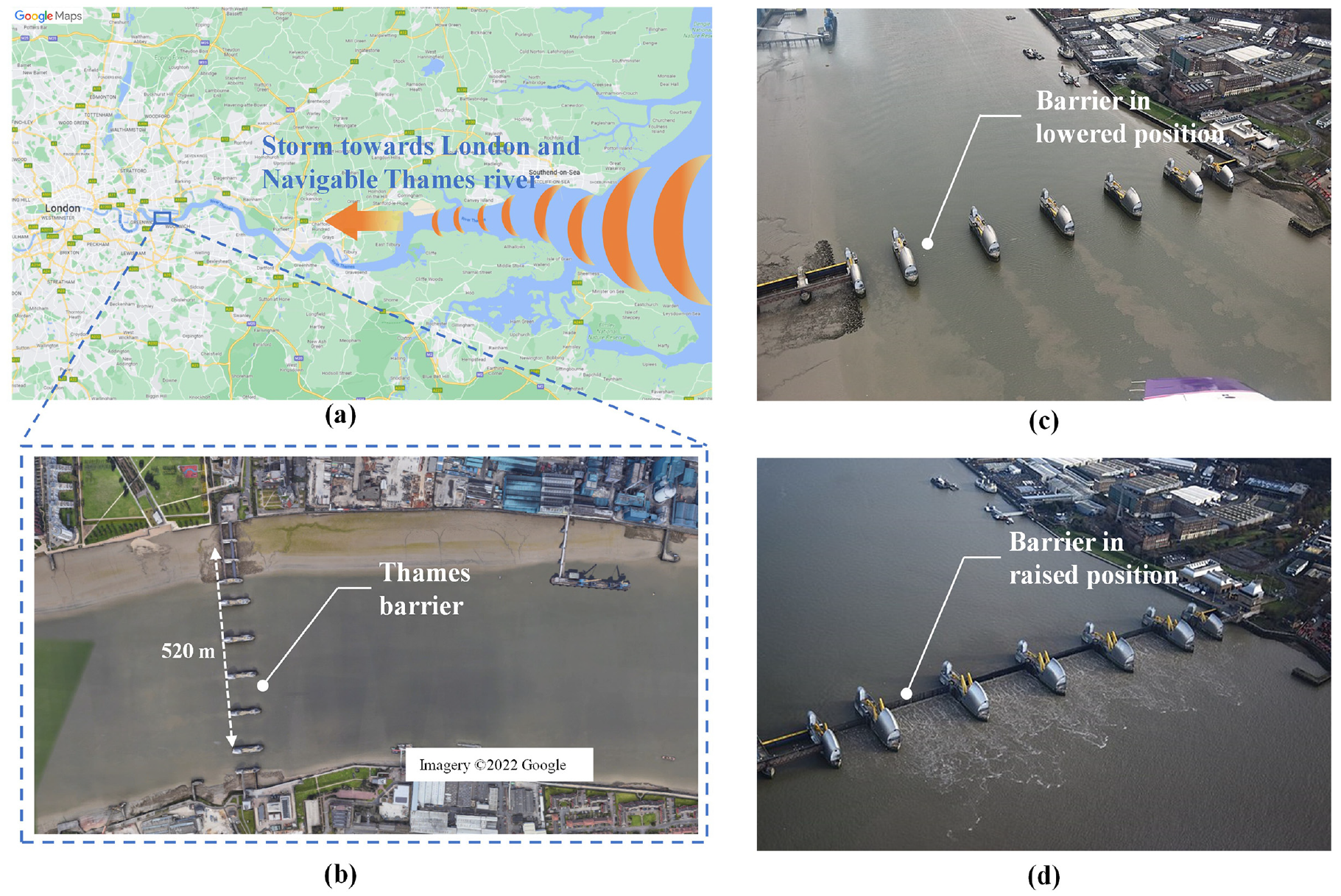
The Thames barrier: (a) the location of the barrier with a depiction of a storm, (b) satellite view of the barrier (Imagery ©2022 Bluesky, Getmapping plc, Infoterra Ltd & Bluesky, Maxar Technologies, The GeoInformation Group, Map data ©2022), and (c) the barrier in a lowered position 288 (d) and a raised position, 289 that is, opened and closed for navigation, respectively.
The Thames barrier comprises radial and rising sector gates with heavy moving parts such as bearings that rotate partially through 90° and 180° (Figure 10(a)). The position of gates and the bearing movement are continuously monitored through a SHM system installed by Monitran, UK. 67 The sensors are installed on bearings on the outer faces which are subjected to hydraulic and tidal forces of the river. Each bearing is instrumented with four Eddy current sensors for displacement measurements, a pressure sensor for measuring the height of the tide, an inclinometer for recording the position of the gate, and an accelerometer in the center for measuring vibrations (see Figure 10(b)). All the data acquisition is performed through a wired network and hence, the installation of the SHM system through narrow and rotating components poses a challenge to engineers. A report on the Thames Estuary 2100 (TE2100) project for London emphasized the need for monitoring the usage and functioning of the Thames Barrage due to changing water levels and barrier closures to establish requirements of modifications in the barrier or construction of a new barrage. 289 A decade after the report, the mentioned risks were verified, and it was reported that the repaired defenses (over 3000) such as quay walls and embankments are regularly inspected for their conditions. 290
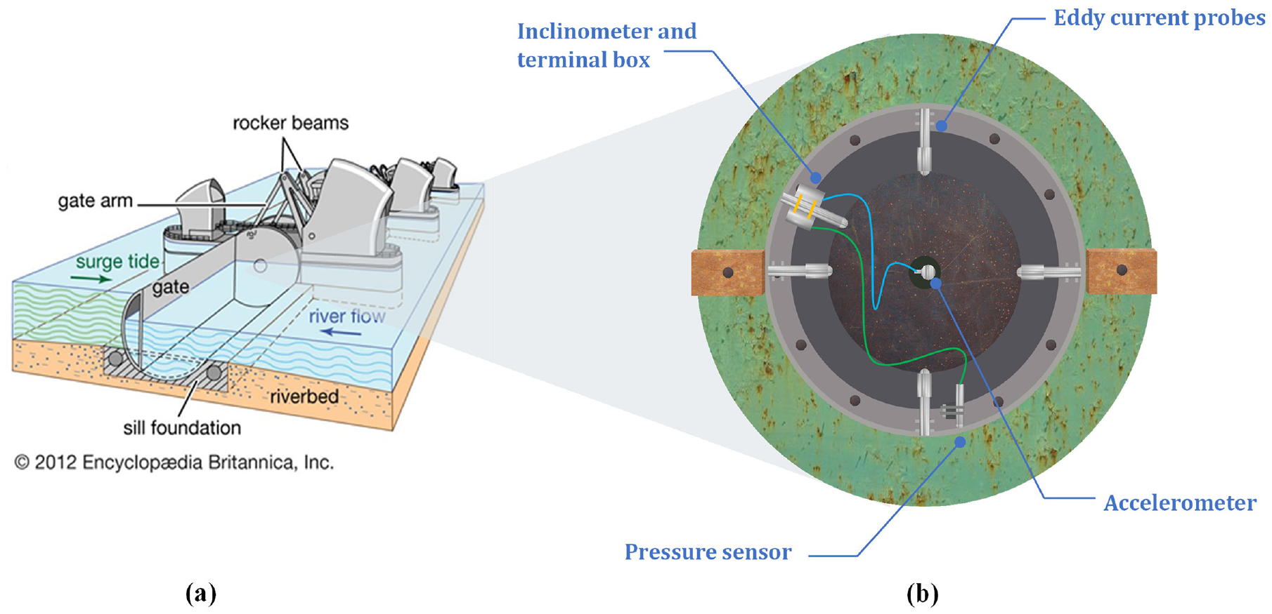
Navigable aqueducts (bridges for waterways)
The Magdeburg Water Bridge in Germany, the Ringvaart Aqueduct and the Gouwe Aqueduct in the Netherlands, and the Briare Aqueduct over the Loire in France are examples of modern navigable aqueducts. Navigable aqueducts are generally monitored for multiple parameters during and after their construction. The available literature on SHM of navigable aqueducts is limited. The Magdeburg Water Bridge (see Figure 11(a)) is the longest navigable aqueduct in the world. It spans 918 m and operations since 2003. It is monitored for settlement of piers, temperature of steel structure and water, forces in all bearings, and anchor forces in the anchor system at the approach bridge, as illustrated in Figure 11(b). 292
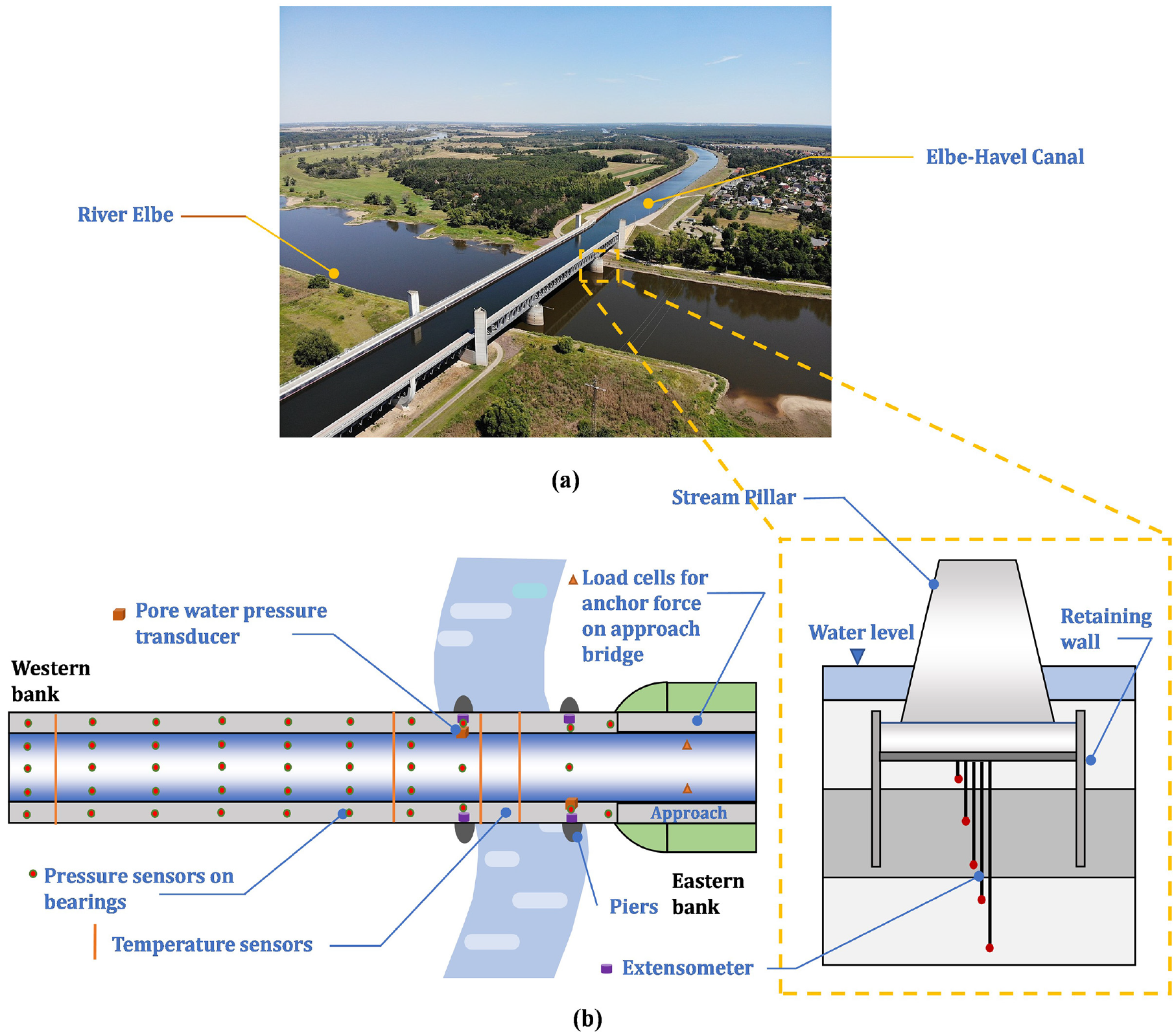
The major stressors in aqueducts are due to the change of the water level and temperature in structural members. The operators of the Magdeburg Water Bridge decided to run a complete check-up in 2008 by emptying the trough. It was observed that some of the pressure sensors malfunctioned and the values of pressure in some bearings were highly scattered. Hence, it was decided to calibrate sensors ensuring the acquisition of the correct response of the structure. 293 Later, Resnik and Ribakov 294 performed geodetic monitoring of the water bridge using accelerometers to identify signs of its deformation. They measured the dynamic behavior of the structure at multiple locations along its length. They reported changes in dynamic parameters, such as shifting of resonant peak amplitudes due to changes in temperature and traffic. Some studies exist on monitoring aqueducts that are not used for navigation. Deng et al. 295 installed resistance SGs on the Cao River aqueduct (China) to measure strains in its span during and after impounding. They observed no changes in existing concrete cracks and minor changes in the stresses due to impounding.
Aqueducts are also monitored for the effect of land subsidence. Wang et al. 296 used Sentinel-1 two-year data for the InSAR technique to measure deformations in the middle route of the South-to-North water division project, China. There are multiple water aqueducts in this route, out of which two pass from a subsidence area formed due to mining. They observed a maximum deformation rate of 20 mm/year in the canal section. This was validated with in situ leveling. However, the overhead aqueducts were relatively stable due to deep pile foundations. InSAR displacements were also suggested for the calculation of the changes in the water flow and for the identification of areas susceptible to damage in the structure of the California Aqueduct. 297
Ship lifts (lift locks)
Ship lifts, boat lifts, or lift locks lift vessels between two water bodies at different elevations in a waterway (see Figure 12(a)). These structures are not very common, as they are built when the elevation difference is significantly high and requires multistage canal locks. Ship lifts have replaced multistage locks in several sites in the world, reducing total passage time by 3–5 times. The Three Gorges Ship Lift in China, the Niederfinow Boat Lift and the Scharnebeck Twin Ship Lift in Germany, the Strépy-Thieu Boat Lift in Belgium, and the Peterborough Lift Lock in Canada are a few examples.
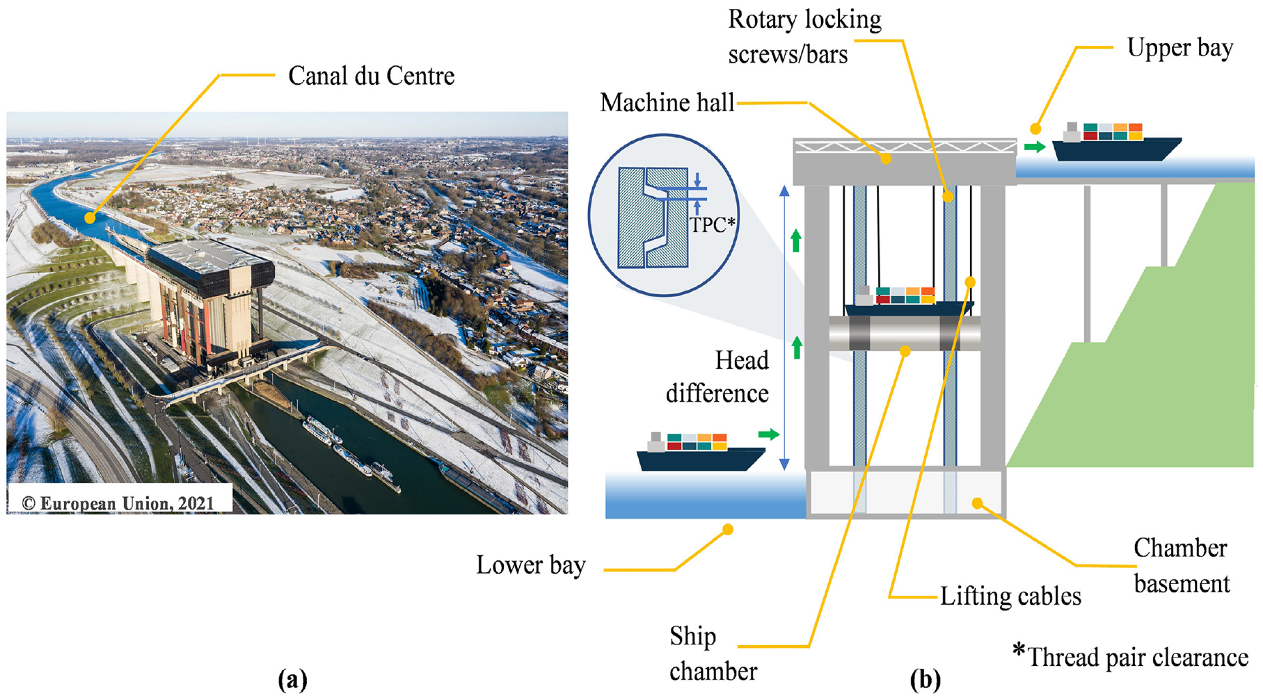
(a) An aerial view of the Strépy-Thieu Boat Lift in Belgium 298 and (b) a sketch of a ship lift and its safety function, the rotary locking screws.
Ship lift have millimeter-precision equipment managing large loads within, usually, concrete structures. The equipment comprises electromechanical systems, including counterweights, winches, ropes, and electric motors to lift a vessel vertically along with the water, which is in the range of several thousand tons. For large vessels, ship lifts can be bottlenecks, as the water depth in the trough, and the amount of impact exerted on the gate barriers can be a constraint. 299
The pitch stability of vertical ship lifts during hydraulic loading is a matter of concern, reducing productivity and posing risks of operational safety. 300 Monitoring chamber levels ensures synchronous and safe lifting of the chamber. High-capacity load cells are installed on the control cables to monitor the load and ensure a correct balance force among them. 80 The main lifting mechanism is controlled by four main drive motors, which are monitored for torque outputs with torque transducers to ensure a power equilibrium. 301 As the load is lifted using balanced counterweights, any leakage in the trough or sudden movement of the vessels while lifting can disrupt the balance causing the development of excessive stresses. Ship lifts are regularly inspected and, if required, undergo destructive tests like concrete core extraction. 302
Commonly, ship lifts are built in canal segments having a controlled water discharge and flow velocity. In case if ship lifts are built alongside large dams, the discharge from spillways during floods and the operation of the powerhouse cause undesirable vibrations in ship lifts. Xu et al. 34 monitored the vibration response of the Xiangjiaba Ship Lift (China) for 2 years. They observed a confirmed impact on the ship lift tower due to the discharge of floods through spillways. However, the measured vibration amplitudes were in the safe range. The pulsating nature of discharge (2 Hz) was in the range of the third (2.52 Hz) and fourth (2.87 Hz) modal frequencies of the tower.
The Three Gorges Ship Lift is the highest in the world. It is 113 m in height, and its maximum carrying capacity is 3000 tons. 303 During its construction, the support towers were monitored for deformations using a 360° prism and a total station with a monitoring frequency of one recording per day. 304 The deformations were within 2 mm, which was acceptable as per the design. However, as the ship lift is a thin-walled structure, it shows identifiable deformations with temperature changes. The rotary locking screw, which is a safety feature, is also monitored for the change in thread pair clearance (as shown in Figure 12(b)) due to wear. 305 The ship lift is installed with pressure sensors to measure pressure in the hydropneumatic spring, magnetostrictive sensors for measuring vertical displacements in the test rack and the shaft, and tilt sensors for measuring tilt at shafts and frame rings. Variations of the water level in the chamber exert an elastic deformation in it. Over time, this phenomenon can cause unwanted wear in the rotary screws, thus leading to a loss in thread pair clearance and putting the safety mechanism at risk.
The towers that support the heavy machinery room and the entire shipload during lifting are not braced for lateral stiffness. The deterioration of the construction material might decrease the overall stiffness of the structure, which can be unsafe. This can further affect the pitching stability of a completely hoisted ship lift, due to the changes in primary structural parameters. 306 Large ship lifts are not common; thus, the assessment of design parameters may be subjected to some uncertainties due to limited expertise with such structures. 307 Also, during the hung condition, seismic activity can give a rise to coupled vibrations between the structure and the ship chamber, thus aggravating the situation further. 38 This confirms that condition monitoring is crucial for ship lifts constructed in environmentally harsh conditions and seismically active regions.
Summary
This section discussed examples of monitoring accessory structures whose effective functioning is critical for the smooth running of inland navigation. Such SHM studies are not widely available. The majority of them are documented by the industries that installed sensors and performed condition monitoring, and only a few were published in scholarly journals. In the last three decades, the expansion of trade through waterways resulted in the construction of new ship lifts, and water bridges having unique designs and use. Traffic in inland waterways have increased and will continue to increase as a result of expanding global trade. In such a scenario, it becomes critical to monitor these structures due to their increased use and environmental stressors, and ensure that they are resilient to unforeseen events.
Added value of SHM systems for INS and ports
This section summarizes the added values of SHM systems for INS and ports that can be considered by the asset owners when deciding on the installation of a SHM system for the structure(s). Also, the added values highlight the importance of further developments and applications of SHM techniques for INS and ports, which are currently scarcely explored/researched. SHM can be considered for:
(i) A reliable measure for condition assessment that adds insights to visual inspections. SHM systems can provide critical information about structural integrity, particularly from areas where visual inspections are not always possible, such as submerged regions of structures. Visual inspections are, in general, scheduled periodically based on past experiences. They are qualitative and require skilled personnel to correlate the present state of the structure to a damage index. Thus, proper quantification of damage in terms of engineering values is unattainable. Whereas a SHM system can measure changes in structural parameters, such as natural frequencies, settlement, etc., and provides reliable information to maintenance teams.
(ii) Ensuring safe operations at the facilities. The impact of operating larger vessels than the current permissible standards set in INS can be monitored. For example, the effect of propeller thrust on scouring of quay walls and chamber floor of a navigation lock can aid in deciding operating policies for large vessels.
(iii) monitoring expansion of the facilities. SHM can be crucial for ensuring a safe expansion of an existing facility by monitoring changes in its structural behavior. Expansions often imply deep excavations, which are accompanied with vibrations, and a diversion of water, which may affect the existing structure. With the support of SHM systems, the scope of construction of new facilities over existing ones can be considered, when ensuring safe construction and operations. 18
(iv) Assessing structural integrity of INS after adverse events. SHM can provide a better and safer insights than routine inspections in assessing the condition of structures after undesirable events (e.g., floods, storm surges, barge impacts). For example, a stretch of a dike may become inaccessible for inspectors during floods. For situations like this, real-time insights from a SHM system or using advanced monitoring techniques can assist making timely decisions about the (re-)use of the facility.
(v) Monitoring repaired and retrofitted INS. SHM can support the optimization of the maintenance operations and resources by assessing quantitatively improvements in the structure, which is challenging with visual inspections as they are rather qualitative. In addition, the performance of structures undergoing repair or retrofit can be analyzed to ensure the effectiveness of repair measures.
(vi) Extending the service life of a structure. SHM can support decisions utilizing a structure beyond its design service life, and provide input for estimating required logistics and finances for replacing the existing structure with a new one or for repairing it.
(vii) Reducing monetary losses due to downtime. Any downtime resulting from sudden breakdowns of critical INS result in monetary losses to asset owners. Losses can be related to repair and maintenance (i.e., direct losses) and freight delays (i.e., indirect losses to the shipowners). In some cases, such circumstances can result in cascading effects such as extended delays. 308
Conclusions and future scope
In this review article, the current state-of-the-art in SHM of INS, such as waterways, dikes and navigation locks, and ports is presented. Sensors and sensing technologies used for SHM of INS and ports are described. The need and urgency of inspecting and monitoring aging, as well as newly developed facilities, is emphasized in the context of the climate change and the increase in trade. Developments and applications of sensing technologies, as well as pertinent case studies, are given, subject to availability. SHM technologies are discussed for their applications along with the scope of improvements and future research trajectories.
The main conclusions from the review are as follows:
SHM for INS and ports is under explored. It is evident that even when commercial sensors and proof-of-concept studies are available in this field, there are—up to now—limited case studies that have used SHM technology for monitoring INS and ports. One reason is that the majority of SHM technologies for civil constructions are designed specifically for bridges and buildings.
While concerns over health of INS and ports is particularly growing, evidence suggests that (1) bridges are in better conditions than INS (2) and much future investment will go in INS. According to ASCE’s 2021 report card, in the United States, bridges are grade C, which is a higher grade in comparison to D+ and D given to inland waterways and levees (dikes), respectively, indicating that INS are in worse conditions than bridges. The Dutch Ministry of Infrastructure lists many lock and quay walls, in addition to bridges and roads, as projects needing replacement and renovation; this indicates that (i) INS need replacement/renovation and (ii) the asset owner has the budget for such actions.
The majority of SHM studies for INS have been carried out in controlled laboratory environments. Consequently, there is not much confidence for their reliability in real-life conditions.
Asset owners are reluctant implementing new SHM technologies, even when they have demonstrated promising results. This can be due to several factors, the most important of which are the involved risk of technology failure and the additional expense burden. Aside from that, the loss of revenue caused by the disruption of routine operations of a structure during the installation of an SHM system or acquiring data during an inspection makes asset owners more hesitant to use any new SHM technique.
The lack of appropriate SHM norms and standards obscures the significance and necessity of implementing SHM systems in any civil structure.
New technologies may overcome challenges for monitoring spatially extended structures. In comparison to bridge, INS such as ports, harbors, and dikes cover large areas and may be expanded even further based on future requirements. The recent developments in noncontact and remote sensing technologies present them as a cost-effective and feasible solution for monitoring extended structures such as breakwaters, dikes, and quays. These technologies are critical for emergency inspections, particularly if the facility is inaccessible due to a natural catastrophe such as floods.
A need for collaborative efforts by academia, SHM industry, and government to raise awareness of the significance of SHM in maintaining the safety of INS and its users among the asset owners. The data from field observations on deteriorating conditions of a structure provided by the maintenance professional or asset owners are crucial for academia and SHM industries to develop robust and effective monitoring technologies.
Footnotes
Appendix[ALS,IRCAI,GIS]
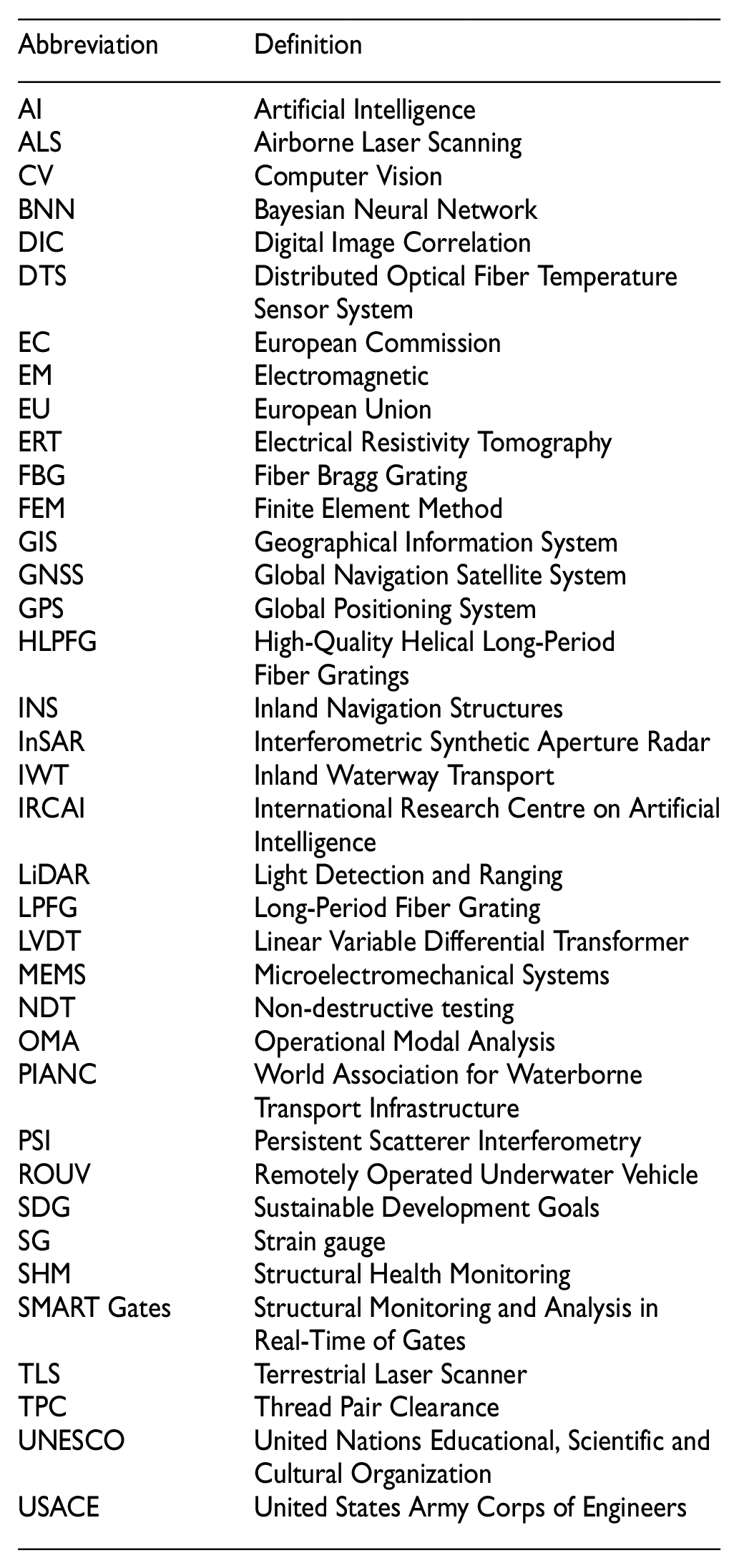
| Abbreviation | Definition |
|---|---|
| AI | Artificial Intelligence |
| ALS | Airborne Laser Scanning |
| CV | Computer Vision |
| BNN | Bayesian Neural Network |
| DIC | Digital Image Correlation |
| DTS | Distributed Optical Fiber TemperatureSensor System |
| EC | European Commission |
| EM | Electromagnetic |
| EU | European Union |
| ERT | Electrical Resistivity Tomography |
| FBG | Fiber Bragg Grating |
| FEM | Finite Element Method |
| GIS | Geographical Information System |
| GNSS | Global Navigation Satellite System |
| GPS | Global Positioning System |
| HLPFG | High-Quality Helical Long-PeriodFiber Gratings |
| INS | Inland Navigation Structures |
| InSAR | Interferometric Synthetic Aperture Radar |
| IWT | Inland Waterway Transport |
| IRCAI | International Research Centre on ArtificialIntelligence |
| LiDAR | Light Detection and Ranging |
| LPFG | Long-Period Fiber Grating |
| LVDT | Linear Variable Differential Transformer |
| MEMS | Microelectromechanical Systems |
| NDT | Non-destructive testing |
| OMA | Operational Modal Analysis |
| PIANC | World Association for WaterborneTransport Infrastructure |
| PSI | Persistent Scatterer Interferometry |
| ROUV | Remotely Operated Underwater Vehicle |
| SDG | Sustainable Development Goals |
| SG | Strain gauge |
| SHM | Structural Health Monitoring |
| SMART Gates | Structural Monitoring and Analysis inReal-Time of Gates |
| TLS | Terrestrial Laser Scanner |
| TPC | Thread Pair Clearance |
| UNESCO | United Nations Educational, Scientific andCultural Organization |
| USACE | United States Army Corps of Engineers |
Declaration of conflicting interests
The author(s) declared no potential conflicts of interest with respect to the research, authorship, and/or publication of this article.
Funding
The author(s) disclosed receipt of the following financial support for the research, authorship, and/or publication of this article: Designing Systems for Informed Resilience Engineering (DeSIRE) Programme supported by the Centre for Resilience Engineering of the four universities of technology in the Netherlands (4TU).
_europoortkering.PNG)