
Abstract
Axles are widely used mechanical components in rotating machines. In many applications, axles are exposed to varying environmental and operational conditions, including for example, temperature, load and rotational speed. To apply acousto-ultrasonics–based structural health monitoring for axles, it is in some cases not economically feasible to collect data and to construct a baseline model for each combination of all possible environmental and operational conditions. In consideration of such a practical limit, a novel baseline-free method, called Dynamic Reference Method, is proposed in this article for the detection of transverse cracks in axles. Piezoelectric wafer active sensors are applied for exciting and sensing ultrasonic waves. In case a transverse crack is present in an axle, it is noticed that the crack will sequentially open and close within one revolution of the axle when it is mechanically loaded in the radial direction. Such an opening and closing phenomenon of the transverse crack will influence the propagation of the ultrasonic waves. During the short time of data acquisition, the environmental and operational conditions remain nearly constant and the changes in the propagation of the ultrasonic waves may indicate the appearance of a transverse crack on the axle, and a baseline model for the environmental and operational conditions is not needed. To validate the proposed baseline-free method, an axle is put on a rotating bending test rig to first initiate a fatigue crack on the surface of the axle and second to observe its growth. During the test, the ultrasonic waves are measured by piezoelectric wafer active sensor in situ and are analysed online using the proposed baseline-free method. According to the test results, not only can the crack be effectively detected, but also the progressive changes of the crack size can be differentiated. Such results demonstrate the potential of the proposed baseline-free method in condition-based maintenance and predictive maintenance for critical axle components.
Keywords
Introduction
In order to prevent catastrophic failures, safety critical components in civil infrastructure, aircrafts and mechanical systems need to be monitored. For this reason, structural health monitoring (SHM) and non-destructive testing (NDT) techniques are moving into the focus of research communities and potential industrial users. This article presents an acousto-ultrasonics (AU)-based method which has the potential to monitor permanently the health condition of mechanically loaded and rotating axles during operation. Thus, the presented method actually provides the possibility to realize condition-based maintenance (CBM) and predictive maintenance. This in turn will significantly reduce the maintenance cost and increase availability.
AU-based methods are a group of well-established active methods for SHM with a wide range of applications.1–6 These methods use the principle that ultrasonic waves travel through the material and interact with discontinuities in the structure. Such kinds of SHM systems need at least one actuator which is capable of exciting the ultrasonic waves and at least one sensor which is used to measure the structural response. In this study, piezoelectric wafer active sensors (PWASs) are applied considering its small size and reasonable price. PWASs operate on the piezoelectric principle and can function either as actuators or as sensors. They are permanently bonded to the structure. Each structural response has a characteristic wave pattern which is caused by reflections at discontinuities. Possible cracks in the structure will change this pattern. To extract these changes, most SHM systems first need to collect data from the structure in healthy condition to build the so-called baseline. With the help of signal processing and feature extraction, the structural health condition is assessed through the comparison of the baseline and the newly acquired data.2,3 The method which is presented in this study is based on the difference in the propagation of ultrasonic waves that is generated between the opening and the closing of a fatigue crack, and it does not need to collect data from a healthy structure in advance. In this sense, the presented method is baseline-free.
Mechanically loaded and rotating axles often work under varying environmental and operational conditions (EOCs), for example, temperature, rotational speed and load. In some earlier studies, it has been reported that temperature has dominant effects on the ultrasonic wave propagation. In order to compensate such temperature effects, methods like optimal baseline selection and baseline signal stretching have been developed by for example, Lu and Michaels, 7 Konstantinidis et al. 8 and Croxford et al. 9 These methods work well for the cases which exhibit a homogeneous temperature change within the monitored structure. However, this is not always the case. In many applications, the distribution and the change of the temperature on axles are not always homogeneous. Furthermore, it might be not economically feasible to collect data and to construct baselines for different types of axles under all different combinations of EOCs. In consideration of such practical factors, this article presents a baseline-free method which is based on the difference that is generated in the ultrasonic wave propagation between the opening and the closing of the crack during operation. The recorded structural response data are analysed with a principal component analysis (PCA)-based damage detection method described by Mujica et al. 10
Methodology
The ultrasonic waves can travel through a structure and interact with discontinuities within the structure. Even in healthy condition, the structure has discontinuities, for example, edges, holes or thickness changes, which influence the propagation of the ultrasonic waves. 11 In this article, the focus is on the difference in the propagation of ultrasonic waves which are generated between the opening and the closing of a fatigue crack in mechanically loaded and rotating axles. The opening and the closing of a fatigue crack during one revolution of an axle is described as the crack breathing mechanism. 12
Influence of the crack breathing mechanism on the ultrasonic wave propagation
During one revolution of an axle, the crack will be fully open/closed or partially open/closed. Assuming an incipient crack on the surface of an axle, the crack will be open at the upper half of the cross-section of the axle when it is under local tensile stress
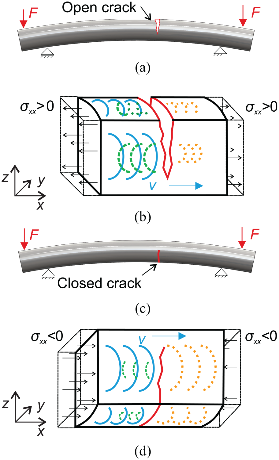
(a) Open crack under local tensile stress, (b) influence of the open crack on the ultrasonic wave propagation, (c) closed crack under local compressive stress and (d) influence of the closed crack on the ultrasonic wave propagation.
In addition, the ultrasonic wave propagation is influenced by the change of the stress distribution surrounding the crack and the crack tip plastic zone.13,14
Figure 2 clearly shows the difference of the stress distribution surrounding the crack for an open and a closed crack. The pictures were taken from a numerical simulation model of a semi-elliptical crack with the crack length of
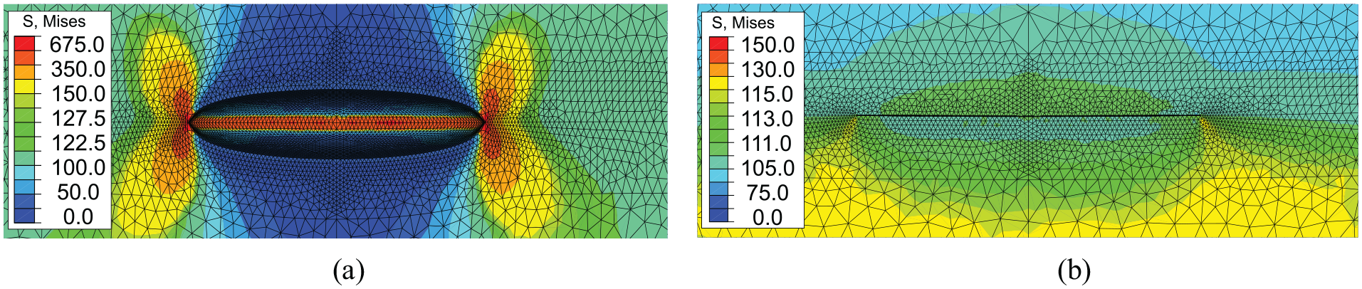
Numerical simulation of the stress distribution for two cases surrounding a semi-elliptical crack with the crack length of
Clark et al. 15 show that the propagation of ultrasonic waves is influenced by the stress distribution surrounding a crack tip. Furthermore, they determine the entire stress field in the region of interest around the crack tip with an acousto-elastic measurement method.
Influence of stress on the ultrasonic wave propagation
The basic theory of the bulk elastic wave propagation for isotropic material subjected to stress is proposed by Murnaghan.
16
Based on this theory, Hughes and Kelly
17
developed the formulation of the influence of stress distribution on the propagation of ultrasonic waves in the theory of acousto-elasticity. They consider the change in wave-speed in isotropic elastic materials in the presence of uni-axially applied stress and hydrostatic pressure. The velocity of the longitudinal wave

The velocity of the shear wave propagation in the direction of the applied stress
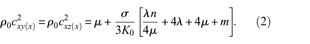
Equations (1) and (2) are dependent on the two Lamé constants
In this article, mechanically loaded and rotating axles are under investigation. Due to the loading condition, a bending stress appears in the structure. The influence of bending stress on the propagation of ultrasonic waves in an elastically deformed material is described in, for example, Si-Chaib et al.
18
in which numerical and experimental evaluations are made to study the change in the wave velocity of longitudinal and shear waves in a cylindrical sample under three-point bending. For the half of the cross-section of the sample under local tensile stress, the longitudinal wave velocity decreases while the shear wave velocity polarized in the
For the described sample in this article, the stress distribution will also change during one revolution of the axle, which will lead to a dependence of the ultrasonic wave propagation on the rotation angle of the axle. The influence of stress on the ultrasonic wave propagation are provided in the section on the experimental results.
Damage detection
The main steps of the presented baseline-free method are illustrated by the flow chart in Figure 3. The core of the process is the Dynamic Reference Method, which will be described later.
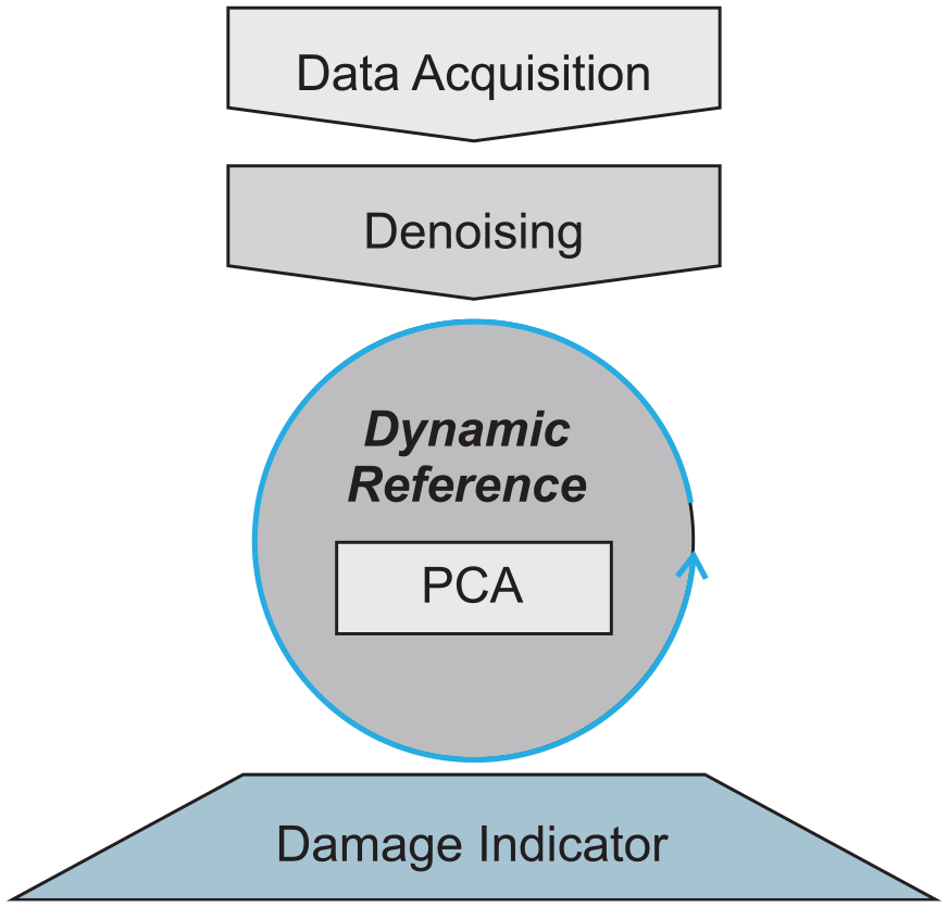
Main steps of the applied damage detection method.
Data acquisition and denoising
In the first step, the structural response data are acquired at different rotation angles
In the denoising step, the recorded data sets are processed with digital filters and discrete wavelet transform (DWT) in order to enhance the useful information in the data. In the present article, the wavelet multi-resolution analysis (WMRA) is used as a kind of low-pass filter to reduce noise in the sensor signals. 19 This method is widely used to reduce noise in sensor signals very efficiently. 2 For filtering, the DWT is terminated after a certain level and the approximation of the signal, which contains the low-frequency components of the signal, is used as the filtered sensor signal. 19 The level of the DWT is chosen so that, based on the sampling frequency, the maximum frequency of the approximation of the signal is close to the highest frequency of the frequency range of the excitation signal. In this article, Daubechies-wavelets db8 are used. 20 Remaining undesired low-frequency components in the structural responses are filtered with a Butterworth-filter (high pass). The cut-off frequency of the filter is close to the lowest frequency of the frequency range in the excitation signal. The filter coefficients are calculated with the Signal Processing Toolbox of MATLAB. 21
PCA
To detect the difference in the ultrasonic wave propagation, the following damage detection method based on a statistical approach is used.
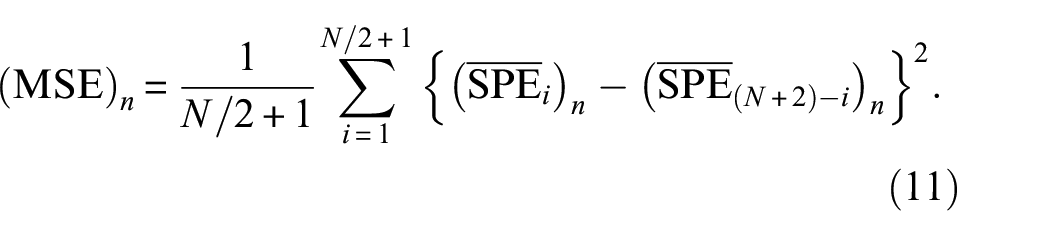
The denoised data are compressed with the help of the PCA technique which is an eigenvector-based multivariate statistical approach to reduce a complex data set to a lower dimension and to extract hidden features. Details on the PCA technique can be found in. for example, Jolliffe’s study. 22 The damage indicator is calculated in the form of a squared prediction error (SPE) which is sensitive to changes that are not represented by the PCA model. 10 The main equations in PCA and the equation for calculating the damage indicator are provided below.
For the purpose of building the PCA model,
The covariance matrix

The eigenvectors

The eigenvectors

For the full set of eigenvectors, which means

PCA-based SPE
Based on the difference between

The variability of the data projected within the residual subspace is represented by the SPE and is defined for the

The SPE quantifies the difference between a sample and its projection into the PCA model, which indicates abnormal situations.
With the described statistical approach, the presented SHM method evaluates the differences during the rotation of the axle caused by the crack breathing mechanism. In this study, a PCA model is built with a data set which is recorded at one reference rotation angle
In order to compare all data sets which are recorded at different rotation angles
Dynamic Reference Method
In this study, a Dynamic Reference Method is proposed and applied for the detection of transversal cracks in mechanically loaded and rotating axles. This methodology is based on the acousto-elastic effect and the crack breathing mechanism.
As previously discussed in the section “Methodology”, the stress distribution has a significant influence on the propagation of ultrasonic waves. The difference in ultrasonic wave propagation compared to the ultrasonic wave propagation at
For an undamaged mechanically loaded axle, the stress distribution for the rotation angles
The changes in ultrasonic wave propagation due to the stress dependence can be quantified by the SPE. Quiroga et al. 24 show that the PCA and in particular the SPE is able to differentiate various stress scenarios in cylindrical steel specimens using PWAS and ultrasonic waves.
For an undamaged mechanically loaded axle, the pattern of the SPE values for one revolution theoretically increases for the rotation angles
For a damaged axle, the crack will be fully open/closed or partially open/closed during one revolution. As previously described, the crack breathing mechanism influences the ultrasonic wave propagation and generates a difference in ultrasonic wave propagation between an open and a closed crack. The influence on the ultrasonic wave propagation will lead to a change in the pattern of the SPE values. Due to such a change, the pattern of the SPE values is no longer symmetrical to
Using only one randomly chosen reference rotation angle
Dynamic Reference Method.
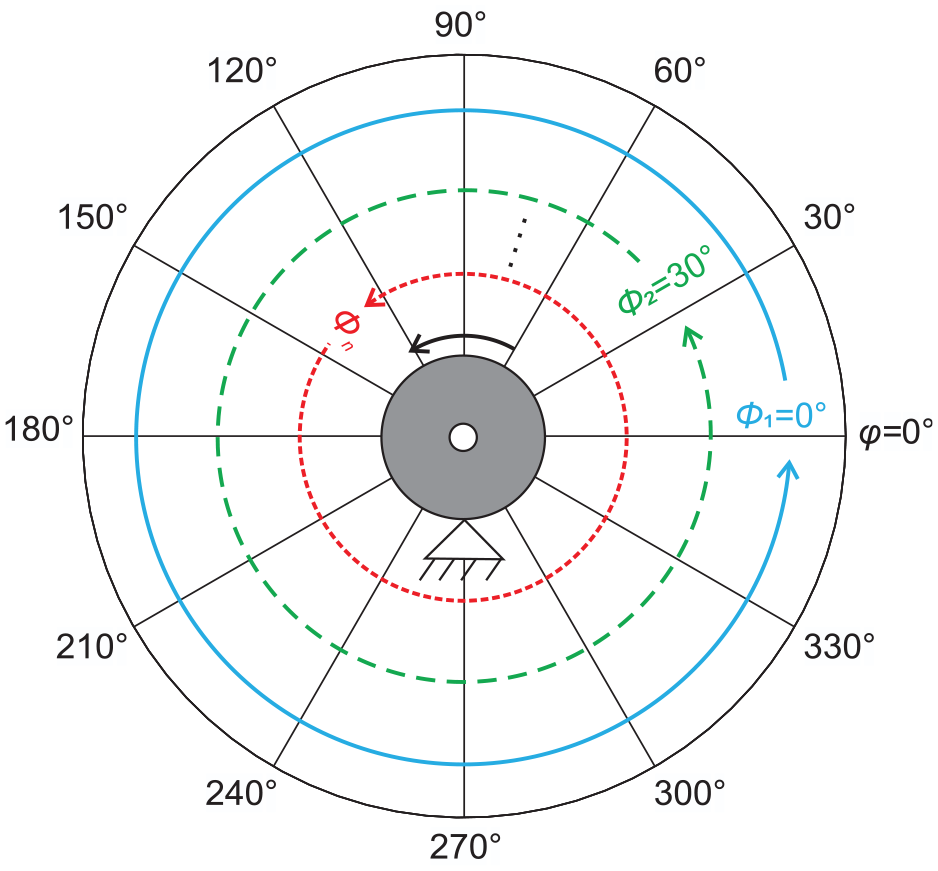
The Dynamic Reference Method can be divided into different steps. In the first step, the data sets are recorded at different rotation angles
For each reference rotation angle
Basically, the Dynamic Reference Method can be broken down into individual analyses. The reference rotation angle


It has to be mentioned that there is no need for new measurements for the Dynamic Reference Method. All analysis is performed based on the same data sets.
For an undamaged mechanically loaded axle, it is expected that the pattern of the SPE values is nearly symmetrical to
For a damaged mechanically loaded axle, an angle-dependent influence, such as the crack breathing mechanism, leads to different patterns of the SPE values in dependence of the reference rotation angle
Damage indicator for the Dynamic Reference Method
In order to detect and to localize a crack, it is necessary to quantify the symmetry of the patterns of the SPE values. One possible indicator is the correlation coefficient
For an undamaged mechanically loaded axle, a correlation coefficient
Using the Dynamic Reference Method, the correlation coefficient
In order to visualize the health condition of the mechanically loaded and rotating axle during operation, the correlation coefficients
A single damage indicator to quantify the symmetry of the patterns of the SPE values for all reference rotation angles

In such a manner, cracks can be detected with the proposed Dynamic Reference Method, and previously collected baselines for different EOCs are not needed. The reference data sets are all taken during a short time of data acquisition during a few revolutions of the axle. During the short time of data acquisition, the EOCs remain nearly constant, and the methodology focuses only on the difference in ultrasonic wave propagation due to the changing stress distribution and the angle-dependent influence of the crack breathing mechanism. In this sense, the Dynamic Reference Method is baseline-free.
Experimental setup
In order to validate the method described in the previous section, a dynamic experiment was performed. The test object is a hollow steel axle with several diameter transitions between 130 and 205 mm and a length of 2200 mm. In the experiment, the axle was put on a rotating bending test rig to first initiate a fatigue crack on the surface of the axle and second to observe its growth. With the rotating bending test rig, it is possible to apply a rotating bending moment as it appears in real operation. A drawing of the test rig is shown in Figure 5. To control the location of the starting crack and to accelerate this process, a small notch (drilled hole with a diameter of 1 mm and a depth of 1 mm) is introduced in the axle at a transition between a diameter of 170 and 205 mm, before starting the dynamic test. At the position of the notch, the axle is a hollow cylinder with an outer diameter of 170 mm and an inner diameter of 30 mm. During the operation of the rotating bending test rig, sensor data are recorded and analysed on-line to monitor the health condition of the axle. As a reference, crack propagation gauges are applied to monitor the crack growth during fatigue.
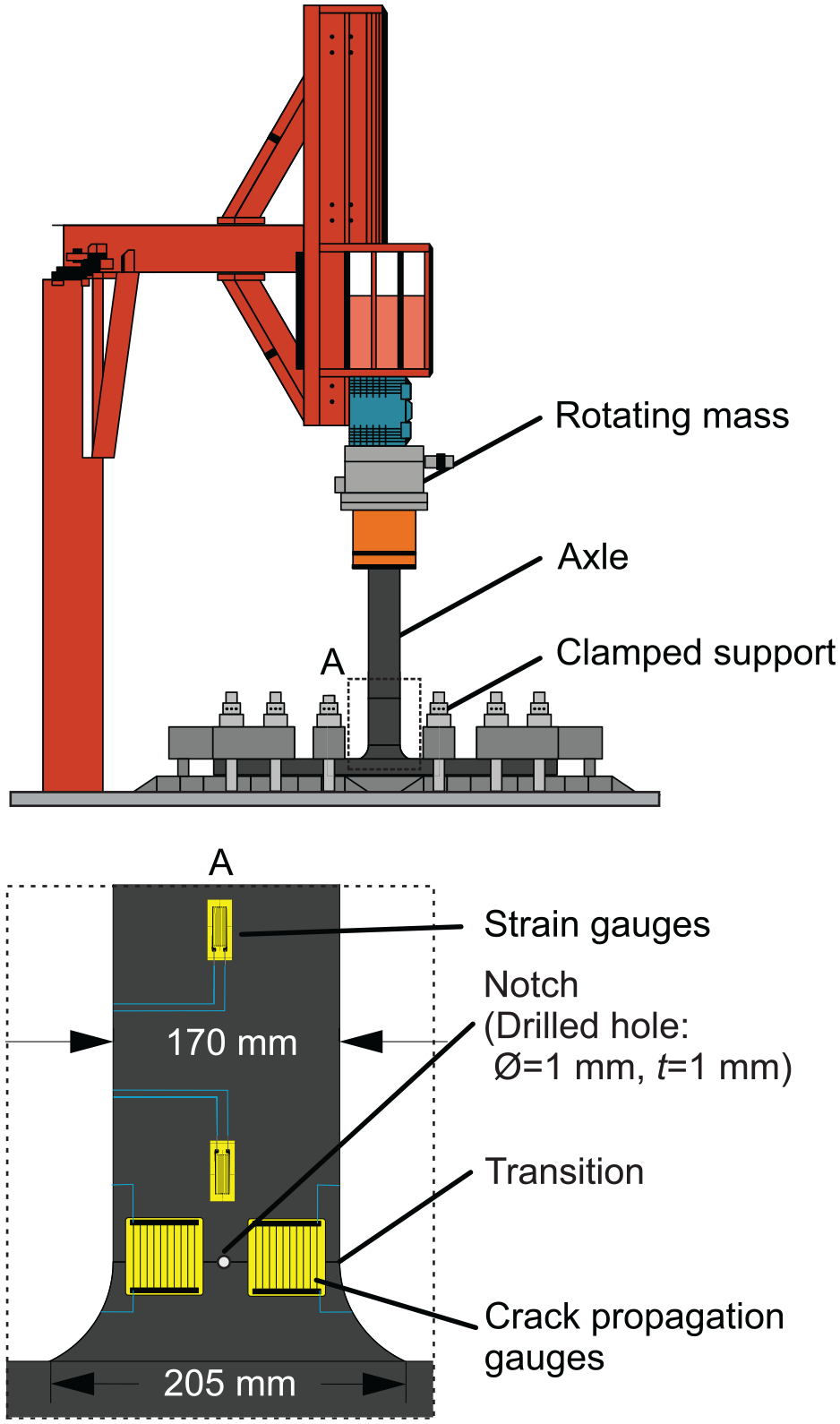
Rotating bending test rig to initiate a fatigue crack and to observe its growth on the surface of an axle.
Figure 6 shows the setup used for data acquisition. A PWAS is attached to the front surface of the axle. The PWAS is used as an actuator and as a sensor using a transmit and receive switch (T/R-switch).28,29 A high-resolution oscilloscope is used for generating the excitation signal for the actuator and acquiring the measured structural response. A sampling rate of
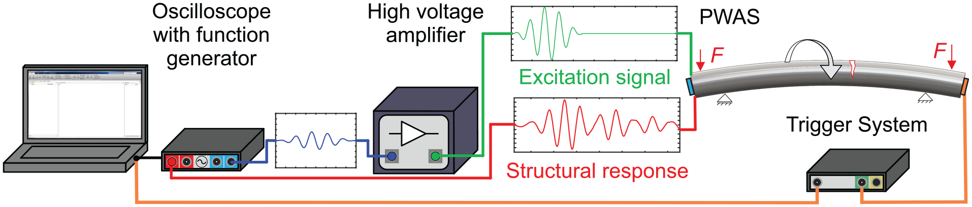
Hardware components of the measurement chain for the Dynamic Reference Method for the detection of cracks in mechanically loaded and rotating axles.
The data are recorded at different rotation angles
The results from the dynamic experiment are provided in the next section.
Experimental results and discussion
In the following section, the proposed baseline-free AU-based method for detection of cracks in mechanically loaded and rotating axles is validated. First, the influence on ultrasonic wave propagation due to a rotating bending moment in the axle is considered. Then, the Dynamic Reference Method for crack detection is applied during the rotating bending fatigue test. Different crack sizes are considered. This is followed by an investigation of the influence of different stress levels on the Dynamic Reference Method for crack detection during the rotating bending fatigue test.
Influence of an applied rotating bending moment on ultrasonic wave propagation
The following experimental investigation shows the influence on the ultrasonic wave propagation due to a rotating bending moment. With the rotating bending test rig, three different rotating bending moments are realized. The applied rotating bending moments result in stress ranges of
Figure 7 shows the patterns of the calculated SPE values depending on the rotation angle
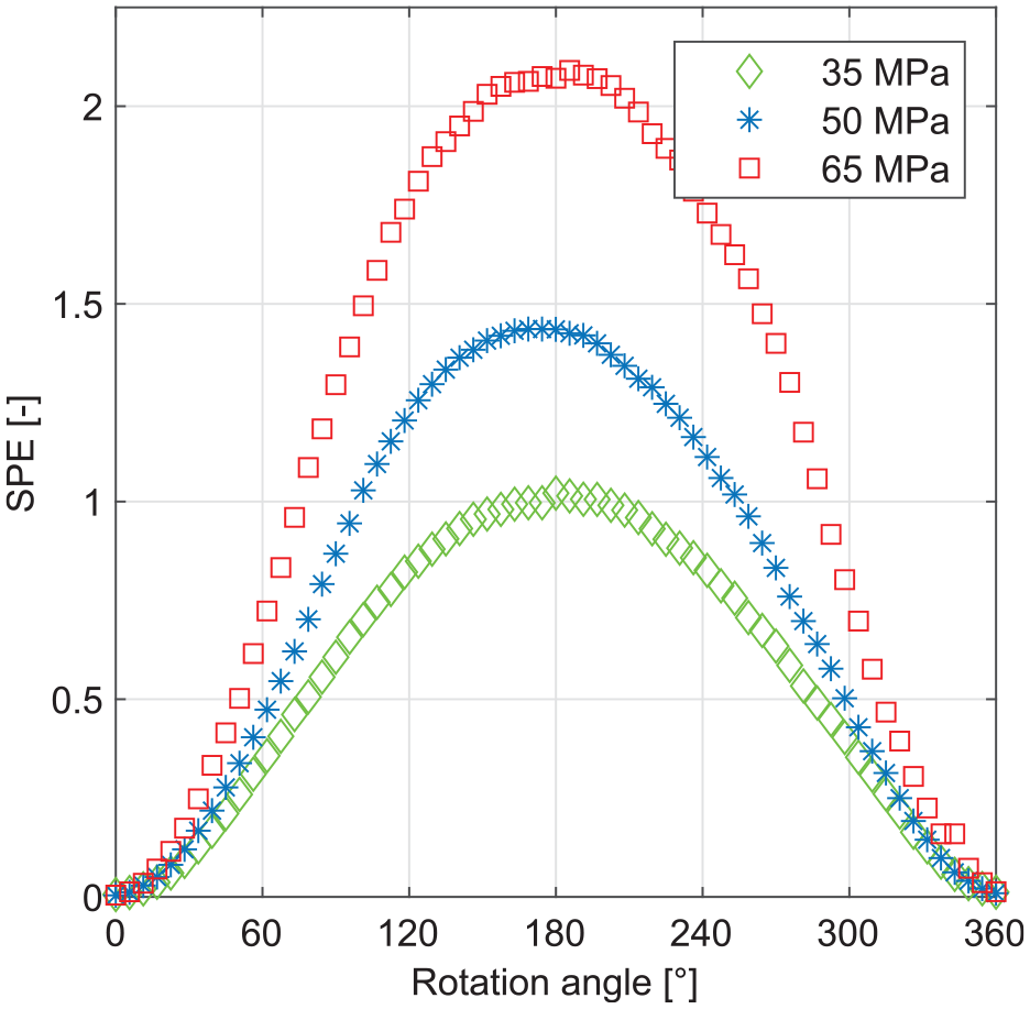
Calculated mean values
As the stress level increases, the maximum of the SPE values at 180° increases. This dependence is caused by the acousto-elastic effect and is described by the equations (1) and (2).
In real operation of an axle, the stress level may not always be the same. To be able to compare different experiments with different load levels in the following, the maximum of the SPE values is normalized to
Application of the Dynamic Reference Method
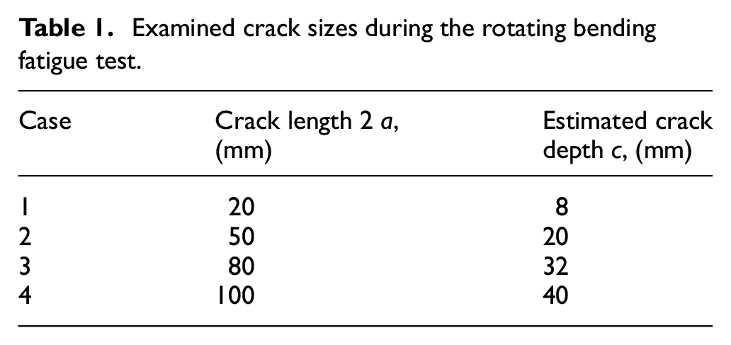
In this section, the Dynamic Reference Method for crack detection in mechanically loaded and rotating axles is applied. The data are recorded during the rotating bending fatigue test as described in the section “Experimental Setup.” During the fatigue test on the rotating bending test rig four crack sizes are examined in more detail. The crack sizes are listed in Table 1. The crack length is determined by means of crack propagation gauges. The crack depth
Examined crack sizes during the rotating bending fatigue test.
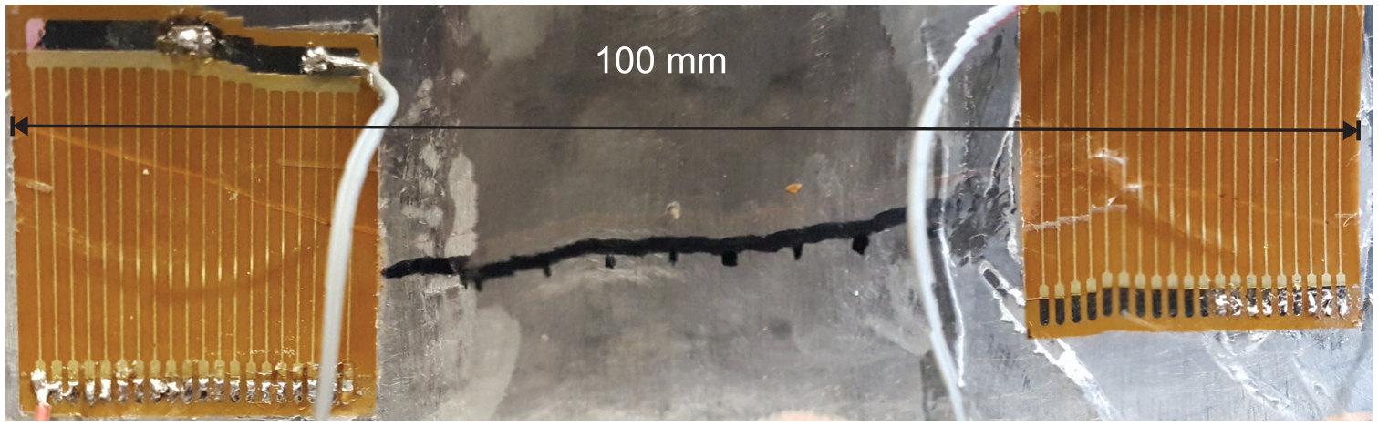
Propagated crack from starter notch at a transition between two diameters of the axle. Crack propagation gauges were applied to monitor the crack growth during fatigue.
Figure 9 shows the calculated mean values
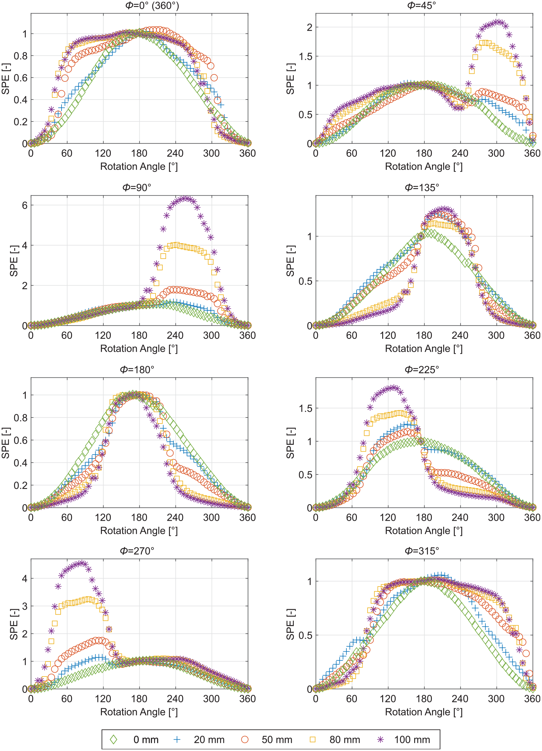
Calculated mean values
For the undamaged case, Figure 9 shows that there is no dependence of the calculated SPE values on the reference rotation angles
In contrast, the results with a crack in the axle are strongly dependent on the selected reference rotation angle
For the reference rotation angles
The patterns of the SPE values for all crack sizes show an obvious deviation from that representing the undamaged case. Furthermore, the deviation increases as the crack size increases. This indicates that the pattern of the SPE values is related with the health condition of the axle, and an unsymmetrical pattern can be considered as an indication of the existence of a crack.
Figure 10 shows a polar plot of the correlation coefficients
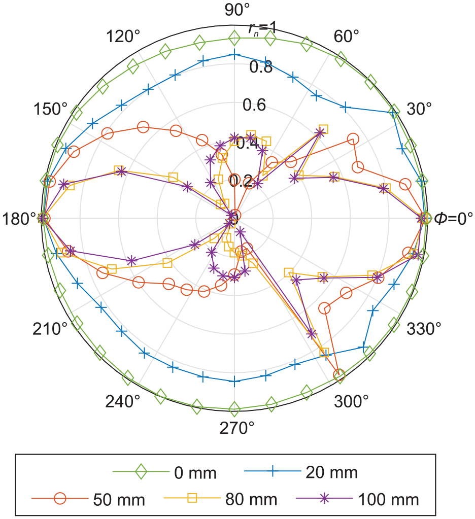
Polar plot of the correlation coefficients
For an undamaged axle, the correlation coefficients
For a damaged axle, no matter which crack size in Figure 10, the correlation coefficients
As previously described, for the reference rotation angles
Nevertheless, correlation coefficients
Influence of rotating bending moments on the Dynamic Reference Method
In order to analyse the influence of rotating bending moments on the Dynamic Reference Method, the fatigue test is interrupted at different crack sizes. During the interruption, data are recorded for different stress levels ranging from 20 up to 155 MPa. The bending stresses in the crack plane are measured with strain gauges.
Figure 11 shows the calculated MSE for all reference rotation angles
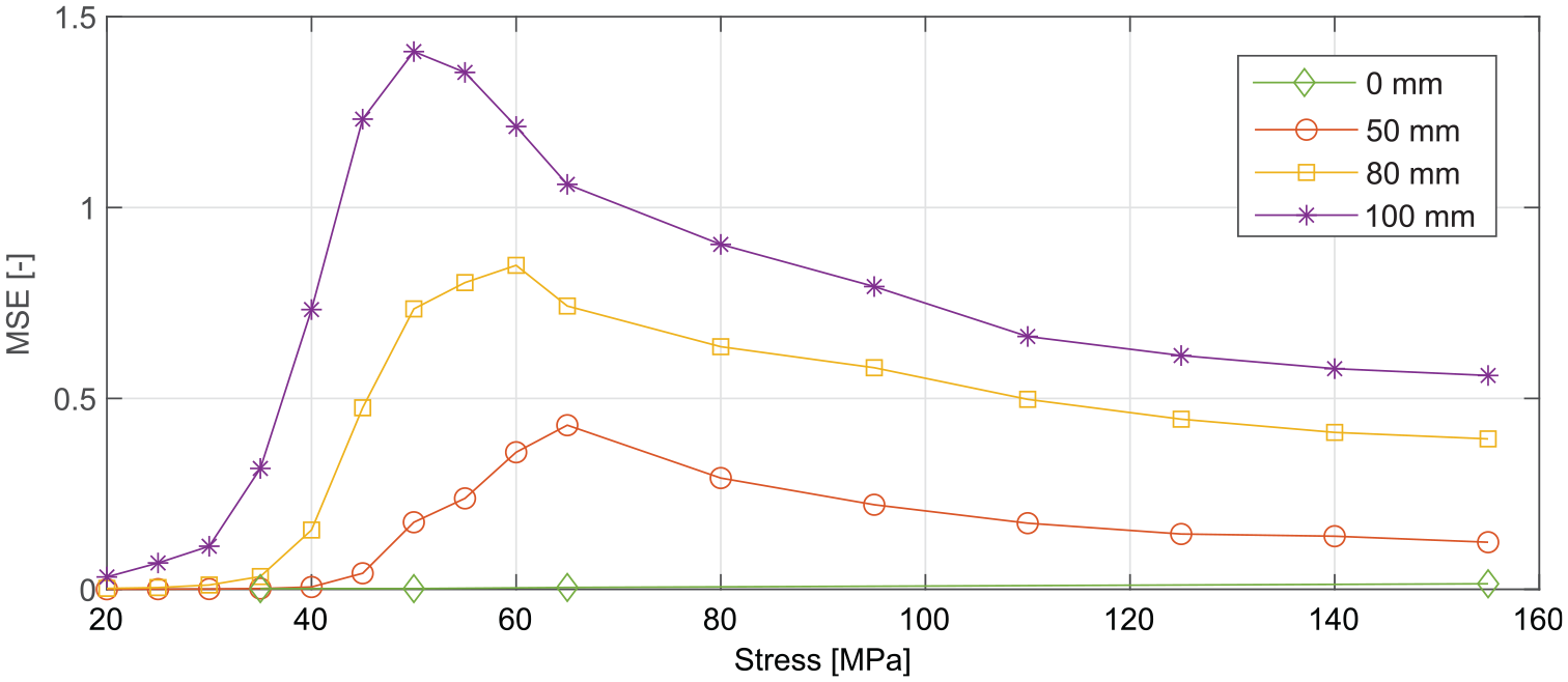
Calculated MSE for all reference rotation angles
In the undamaged case, the MSE is very small and almost independent on the stress level. Only a slight increase can be recognized by increasing the stress level. In comparison to the damaged cases, the MSE can be neglected.
The MSE for the crack sizes of
The MSE first increases to a maximum.
The maximum of the MSE value increases with an increasing crack size.
The applied stress, where the MSE is at a maximum, decreases with an increasing crack size.
If the applied stress further increases after the MSE reached the maximum, the MSE decreases.
For the crack size of
The dependence of the MSE on the applied stress can be explained with the help of the crack breathing mechanism and the theory of acousto-elasticity. For lower stress levels, the crack opening displacement is not enough to fully separate the crack faces due to fatigue crack closure, in particular roughness-induced crack closure, oxide-induced crack closure and plasticity-induced crack closure.
31
The stress, at which the crack opens completely, decreases as the crack size increases. Therefore, the MSE starts to increase for increasing crack sizes at lower stress levels. For a rising crack size, the angle-dependent influences due to the crack breathing mechanism increase, which leads to higher maximum MSE values. By further increasing the applied stress, the change in the ultrasonic wave propagation due to the acousto-elastic effect during one revolution of the axle has a dominant influence on the pattern of the SPE values. As previously described, the maximum of the SPE values at
This investigation thus shows that the crack is detected with the Dynamic Reference Method starting from a certain stress as a function of the crack size, but is less well detected at higher stresses. In real operation, however, a further increase in stresses would lead to a higher crack growth rate, which in turn would increase the level of the damage indicator and thus lead to an early intervention of the proposed SHM system.
Conclusion and outlook
In this article, a novel baseline-free AU-based SHM method for the detection of transversal cracks in mechanically loaded and rotating axles is proposed. The described Dynamic Reference Method utilizes the difference that is generated in the ultrasonic wave propagation between the opening and the closing of a fatigue crack during one revolution of an axle. For the Dynamic Reference Method, a previously collected baseline is not needed.
The proposed Dynamic Reference Method is validated on a mechanically loaded axle through a dynamic experiment on a rotating bending test rig. During the fatigue test, different crack sizes are considered and the influence due to different rotating bending moments in the axle is investigated.
The results from the experiments demonstrate the effectiveness of the proposed method. Cracks can be detected and the crack propagation can be observed during the experiment. Furthermore, the approximate circumferential position of the crack can be localized by the proposed method. The experimental results show a dependence of the proposed damage indicator on the applied rotating bending moment.
As next steps, the Dynamic Reference Method will be validated under consideration of varying EOCs and the correlation between the crack size and the change of symmetry in the profiles of the SPE values will be under investigation. Therefore, more fatigue tests are necessary to statistically validate this correlation. Furthermore, the system will be further developed towards an industrial application.
Footnotes
Appendix 1
Acknowledgements
This research work is part of the SAFE On-Line project (EFRE-0800840) which is financially supported by the European Regional Development Fund (EFRE) and the State of NRW, Germany. Furthermore, the authors would also like to acknowledge the cooperation partners of the SAFE On-Line project: Chair for Embedded Systems from the University of Siegen, Bombardier Transportation GmbH, Sondev GmbH, W.S. Werkstoff Service GmbH and Alpha Trains Europa GmbH. SAFE On-Line is based on patent pub.no. WO/2016/066212 and international application no. PCT/EP2014/073393.
Declaration of conflicting interests
The author(s) declared no potential conflicts of interest with respect to the research, authorship and/or publication of this article.
Funding
The research work is financially supported by the European Regional Development Fund (EFRE) and the State of NRW, Germany.