
Abstract
Acousto-ultrasonic composite transducers (AUCTs), comprising piezoceramic materials in a reinforced polymeric matrix, show promise for structural health monitoring in composite structures. Challenges arise when integrating AUCTs onto highly loaded thermoplastic composites, especially low-surface-energy materials like polyaryletherketone composites. To address this, the study explores the viability of attaching AUCTs to low-melting polyaryletherketone carbon fiber-reinforced thermoplastic composite structures using ultrasonic welding. This welding technique forms a joint where the interface material fuses with the AUCT embedment and the structure matrix, providing a reliable and automatable process. The investigation includes a comparative analysis of an ultrasonic welded joint with an external energy director and a reference AUCT system integrated using a vacuum bagging oven procedure. Results highlight the potential of AUCT configurations integrated by ultrasonic welding as an alternative solution, acknowledging challenges that persist for further development and increased reliability in structural health monitoring applications.
Keywords
Introduction
Composite materials have not stopped growing in the past few years for their excellent properties, such as high specific strength. Recently, new applications have been rising with new materials, such as aeronautic structures based on thermoplastic matrix composites.1–3 Despite the fact that composite structures are designed with principles of safe life and can theoretically withstand critical failure, 4 they are susceptible to impact damage. Especially hidden damage caused by low-speed impacts and fatigue can lead to various types of damage such as delamination, debonding, or fracture on fibers and matrix, decreasing the structures’ properties and compromising their integrity. 5 The detection of these damages is a major issue in the maintenance of composite structures because it demands extensive non-destructive testing, which requires access to the structure and, in some cases, disassembly. Another approach is to use structural health monitoring (SHM), which allows for the transition from time-based to condition-based maintenance and does not require direct access to the structure. With the use of SHM-driven diagnostic and prognostic tools, maintenance can be minimized and reliability increased, making SHM a promising technology for optimized structures. Despite all of the potential benefits of SHM, this technology still needs to mature further, particularly in the area of aerostructures. This is because there are still numerous challenges to overcome, such as the weight added by the various systems and cabling, the increased complexity in the manufacturing phases, the reliability of SHM systems, the implementation cost, or the lack of standards and certifications.6,7
A very promising and reliable SHM technique for detecting damages in composite structures is piezoelectric wafer active sensors (PWAS). 8 Using the direct or inverse piezoelectric effect, piezoceramic materials can be used as sensors and actuators. PWAS can excite and receive acousto-ultrasonic (AU) waves through structures called guided waves (GWs) or Lamb waves when used in thin-wall structures. By comparing the baseline signal of a pristine structure with the actual signal, damages (e.g., impact damages) can be identified. 9 Overall, of the different PWAS available on the market, the AU composite transducers (AUCTs) based on the DuraAct™ design 10 (PI Ceramic GmbH, Lederhose, Germany) are highly reliable in terms of admissible tensile load thanks to their composite construction. 11 However, when they are secondary-bonded onto highly loaded composite structures, ensuring proper joining properties is a challenge. 12 On GW-SHM networks, the transducers are permanently installed, and consequently, the system must ensure an acceptable performance over the lifetime of the structure in its operational conditions.13,14
The conventional approach to attaching AUCTs to structures is by using adhesive bonding, which may not be sufficiently reliable and is difficult to evaluate, especially for low-surface-energy thermoplastics. 15 The use of co-bonding techniques 11 is also inconvenient because the processing temperatures of thermoplastic composite structures are higher than the Curie temperature of piezoceramics, requiring repolarization of sensors or a second co-bonding process below the Curie temperature. New approaches proposed the usage of thermoplastic adhesive films with vacuum bagging oven integration of PWAS onto carbon fiber-reinforced thermoplastic (CFRTP), giving promising results but with a time-consuming and complex integration process.14,16
Welding techniques, on the other hand, can be used to create a joint in which the interface material interfuses with the AUCT embedment and the structure matrix. 17 They are fast integration methods that are easy to automate, resulting in a homogeneous interface. Over all available welding techniques, ultrasonic welding (UW) is a very fast and energy-efficient friction welding technique. 18 With the help of an energy director (ED), a design feature used to facilitate the welding process by focusing and directing the ultrasonic energy to the interface, 19 the parts to be joined are subjected to high frequency (∼20 kHz) and low amplitude (∼39 µm) mechanical vibrations while being subjected to static welding force. Heat is generated by surface friction and viscoelastic heating in the interface with the ED absorbing energy and heating up quickly, creating a localized melting zone. 20 In compatible adherents, when the temperature reaches the glass transition for amorphous materials or the melting temperature for semi-crystalline materials, molecular interdiffusion occurs, creating the joint. In the case of incompatible adherents, such as thermoset to thermoplastic adherents, they cannot be directly welded and require an adhesive interface or a coupling layer. 21 When using adhesive films as ED, instead of joining by molecular interdiffusion, chemical bonds and Van-der-Waals forces are used for bonding.14,16
Considering the aforementioned challenges, the study aims to develop a new approach for integrating AUCTs onto thermoplastic composite structures in a reliable, fast, and automatable way using UW. The first method involves employing the commercially available DuraAct™ AUCTs with adhesive film as ED. The second method focuses on developing a new AUCT design with a compatible embedment matrix for the transducer based on glass fiber (GF) low-melting polyaryletherketone (LM-PAEK).
To investigate the feasibility of using UW to attach AUCTs to thermoplastic composite structures, a set of specimens with two different AUCT configurations on top of CFRTP coupons is manufactured and welded. The welding process is monitored, and the joint performance is characterized. To identify a first approach of suitable welding parameters, a parameter study of the UW process is performed using different monitoring systems. In this regard, control welding machine parameters 22 and infrared thermography 23 are employed. Assessing survivability is determined using electromechanical impedance (EMI), 24 and joint quality is determined using C-scans. The overall SHM system performance is estimated by checking the amplitudes of an AUCT network. 25 Moreover, results are compared to a vacuum bagging oven AUCT reference system to evaluate the potential of the proposed approach.
Materials and methods
Transducer configuration
Two different AUCTs are employed in this study. Firstly, the commercially available DuraAct™ shown in Figure 1(a) is a consolidated product available on the market. DuraAct™ is an AU thermoset composite transducer consisting of a lead titanate zirconate piezoceramic (PIC255 from PI-Ceramic GmbH) covered on both sides by an electrode contacted with a metallized polyester fleece. The transducer is embedded in an external electrically insulating ductile polyester fleece-reinforced polymer laminate, and it includes two contact points for soldering the wires. 10 One of the main features of DuraAct™ over other PWAS available on the market is the induced pre-compression of the piezoceramic during the autoclave manufacturing process. This is due to different coefficients of thermal expansion between the piezoceramic and the embedment composite, which increase the reliability of the transducer under tensile and fatigue loads. 11
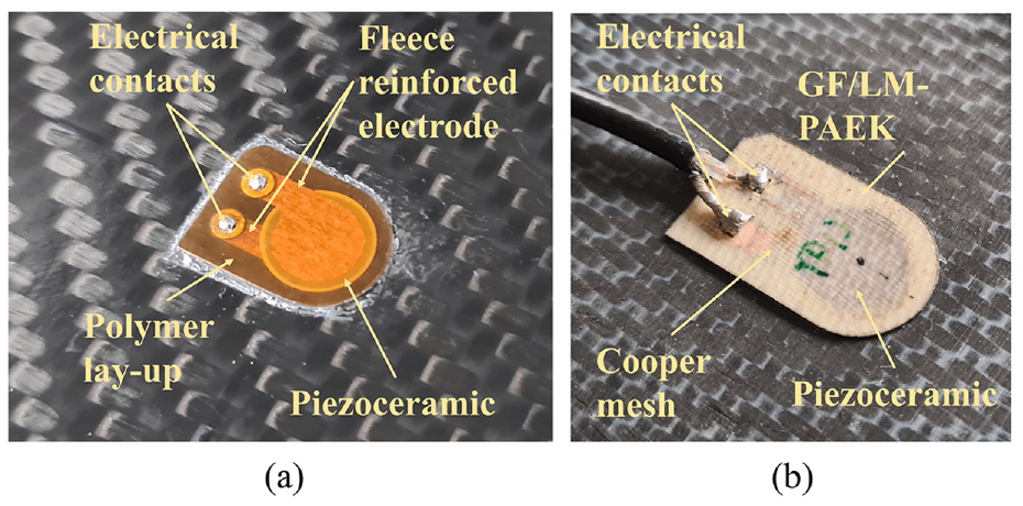
(a) DuraAct™ AUCT and (b) the novel GF/LM-PAEK AUCT.
The second AUCT is a newly developed version depicted in Figure 1(b), based on the DuraAct™ design but with a different material configuration. This allows it to be welded directly onto thermoplastic structures without creating an undesirable interface of dissimilar materials. For this purpose, the embedment on the newly proposed AUCT has been changed from polyester-fleece-reinforced epoxy to glass-fiber-reinforced low-melting polyaryletherketone (GF/LM-PAEK). The electrode contacts have been modified from conductive fleece to copper mesh, and the contact points have been changed to a cooper lamina to withstand the higher processing temperatures. In contrast, the piezoceramic disk, with a 10 mm diameter and a thickness of 0.2 mm, remains consistent with DuraAct™.
LM-PAEK was selected for its high-performance characteristics as a semicrystalline thermoplastic with low moisture absorption, making it suitable for welding or co-bonding in aerospace PAEK thermoplastic composites. As a matrix embedment, it protects the system from external environments while enhancing AUCT reliability under tensile loads by inducing pre-compression in the piezoceramic, effectively behaving as a multifunctional material. The pre-compression occurs during thermal processing, similar to DuraAct™, where the different coefficients of thermal expansion between the embedment and the piezoceramic lead to the embedment shrinking more than the piezoceramic during cooling, resulting in the desired compressive residual stress. With an endset melting temperature of 320°C, slightly lower than the PIC255 Curie temperature, it allows processing without repolarization. In the study, the Victrex plc. LM-PAEK film in combination with 49 g/m2 plain weave GF is used for the AUCT laminate. The addition of GF reinforcement makes the AUCT embedment more rigid and easier to process. Its ability to withstand high temperatures and its low conductivity make it a suitable candidate as a reinforcement. The woven reinforcement provides a certain in-plane isotropy that is desirable for wave sensing and propagation. However, a high fiber ratio can be disadvantageous when maximizing pre-compression, as the coefficient of expansion of GF is smaller than that of LM-PAEK, lowering the resultant coefficient of expansion of the embedment and leading to lower piezoceramic pre-compression. The laminate is prepared and placed in vacuum bagging for subsequent processing in an oven at 330°C to manufacture the GF/LM-PAEK AUCT, resulting in a thickness of 0.5 mm with proper embedment of fibers and the piezoceramic.
Specimen setup
Two different setups are employed in the study. The first setup aims to find the proper welding parameters and assess the joint quality by integrating AUCT on top of a CFRTP coupon. Meanwhile, the second setup is designed to evaluate the performance of different AUCT configurations and integration methods for SHM on a CFRTP plate.
For each setup, a specific CFRTP laminate with a distinct stacking sequence is utilized. In the case of the coupons, a uni-directional (UD) Toray Cetex® TC1225 TP UD tape prepreg T700/LM-PAEK (Toray Advanced Composites Inc., Nijverdal, Netherlands) with a nominal thickness of 0.18 mm laminate of 305 × 305 mm and [0, ±45]2S stacking sequence is selected. Concerning the panel,
For the welding evaluation, once the laminates are consolidated, several coupons of size 120 × 40 mm are cut from the 305 × 305 mm panel, aligning their longer sides with the 0° orientation of the top fibers. The AUCT is positioned at the top center of the coupon, with the ED located between the CFRTP and the AUCT, as schematically represented in Figure 2(a) and in the cross-section representation of Figure 2(b) and (c).
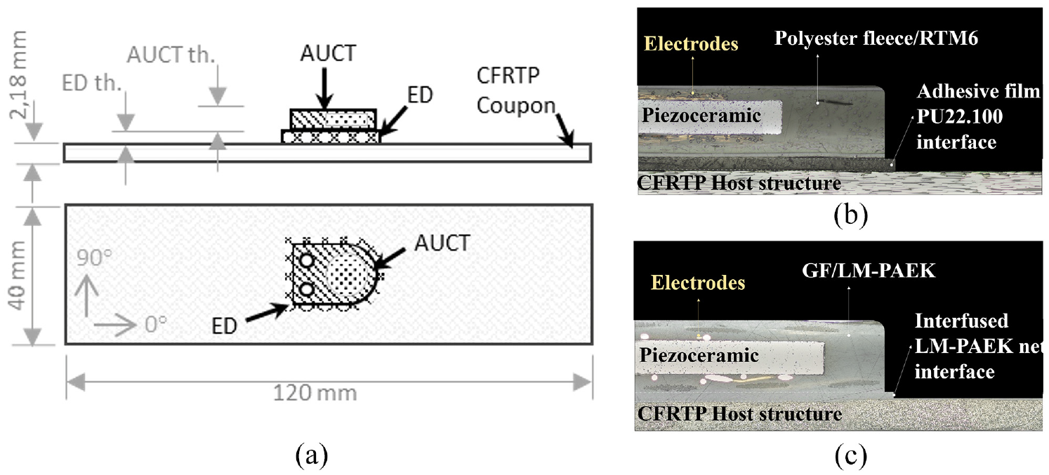
(a) Schematic representation of UD CFRTP coupon for AUCT UW evaluation and cross-section representation of (b) UW DuraAct™ AUCT and (c) GF/LM-PAEK AUCT.
For the SHM performance evaluation, the edges of the 580 × 580 mm panel are trimmed to eliminate manufacturing defects, resulting in a final dimension of 550 × 550 mm. AUCTs are strategically distributed onto the panel in two rows, separated by 300 mm, with four transducers in each row, and a 100 mm separation between transducers. Each type of transducer occupies the same position in both rows, arranged in a manner where each configuration faces its pair in front of it, as depicted in Figure 3.
In the first column position, two GF/LM-PAEK AUCTs with LM-PAEK net as the ED are integrated by UW (1 and 5).
In the second column position, two DuraAct™ AUCTs with PU22.100 from Pontacol AG as the ED are integrated by UW (2 and 6).
In the third column position, two DuraAct™ AUCTs with PU22.100 as the adhesive interface are integrated by oven vacuum bagging, serving as the reference configuration (3 and 7), processed at 140°C for 20 min.
Finally, in the last column position, two GF/LM-PAEK AUCTs with PU22.100 as the adhesive interface are integrated by oven vacuum bagging (4 and 8), processed at 140°C for 20 min.
After AUCT’s integration, they are connected by coaxial cables into a GW-SHM (data acquisition) platform based on the PXIe technology (National Instruments Corp., Austin, US) and into a C-60 impedance analyzer (Cypher Instruments Ltd., London, UK).
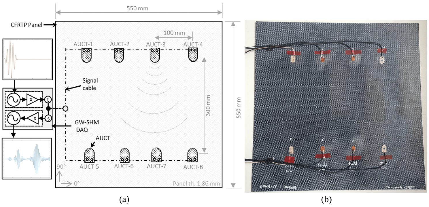
(a) Schematic representation of woven CFRTP panel for SHM performance evaluation and (b) setup.
UW setup
UW is performed using a 20 kHz Rinco Dynamic 3000 ultrasonic welder (Rinco Ultrasonics AG, Romanshorn, Switzerland) the top of the AUCT. The welding direction is defined based on future applications that involve automated processes, where the AUCT will be positioned while the structure is still in the mold. Energy-controlled welding is configured to have the microprocessor-controlled welding unit automatically adjust the electrical power input while maintaining a constant vibration amplitude. In this study, a 1:1 booster and a 1:2.75 sonotrode configuration are employed. The horn has a rectangular shape with a 10 × 30 mm edge length, aligning with the welding parts.
Two main sources are utilized to monitor the welding process. Firstly, the welding unit’s microprocessor records the force, power, and displacement over time. Secondly, the section side of the assembly is thermally monitored using a FLIR A655sc infrared (IR) camera. The surfaces where the coupons and AUCT join are cleaned with isopropanol. The DuraAct™ AUCTs are affixed on top of the CFRTP coupon using polyamide tape, while the GF/LM-PAEK AUCTs are fixed by manual spot UW. The CFRTP coupon is clamped using screwed clamps on the welding structure. Figure 4 depicts the configuration and setup for UW.
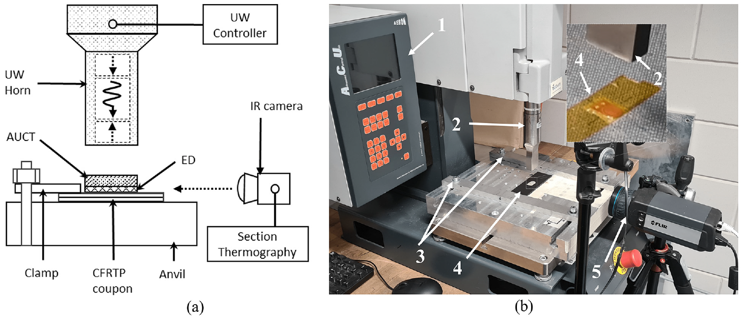
(a) Schematic representation of AUCT UW on CFRTP coupons and (b) setup including UW controller (1), horn (2), clamps (3), CFRTP coupon and AUCT (4), and section IR camera (5).
In the initial phase, a number of specimens are employed to establish suitable welding parameters. Subsequent to these initial observations, a parameter set is narrowed down and optimized based on the visual assessments for six coupons of each AUCT configuration: the DuraAct™ with PU22.100 adhesive film as energy director (ODi), and the GF/LM-PAEK with the LM-PAEK net as energy director (OLi). Table 1 provides the welding parameter values for all specimens.
Coupon AUCT welding parameters.
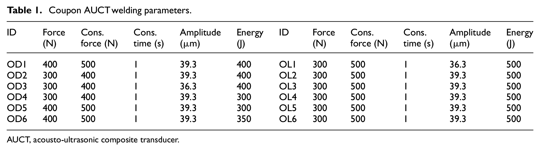
AUCT, acousto-ultrasonic composite transducer.
A Cypher Graph C60 measurement tool is used to conduct an EMI measurement, evaluating the AUCT’s health and joint quality following the welding operation. Additionally, C-scan is performed using an Olympus EPOCG 650 system, which employs automated scanning equipment with the source and receiver located inside a water tank to compare and evaluate bonding quality. Due to setup restrictions, no section thermography is used to monitor the panel AUCT integration. Instead, a parameter set is selected based on the characterization results of the welded coupons to weld the panel AUCTs with increased consolidation time. The welding parameter values for both AUCT configurations are provided in Table 2.
Panel AUCT welding parameters.
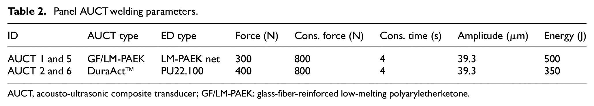
AUCT, acousto-ultrasonic composite transducer; GF/LM-PAEK: glass-fiber-reinforced low-melting polyaryletherketone.
Results and discussions
UW monitoring
Following the adjustments made during the initial tests, AUCTs were welded on top of the coupons and monitored throughout the process. Figure 5(a) and (b) depict the monitored travel as the displacement of the horn in the direction of the thickness, the power as the ratio to the nominal machine power (3000 W), and the force as the reaction force sensed by the horn, over welding time for the DuraAct™ODi coupons and GF/LM-PAEK OLi coupons, respectively.
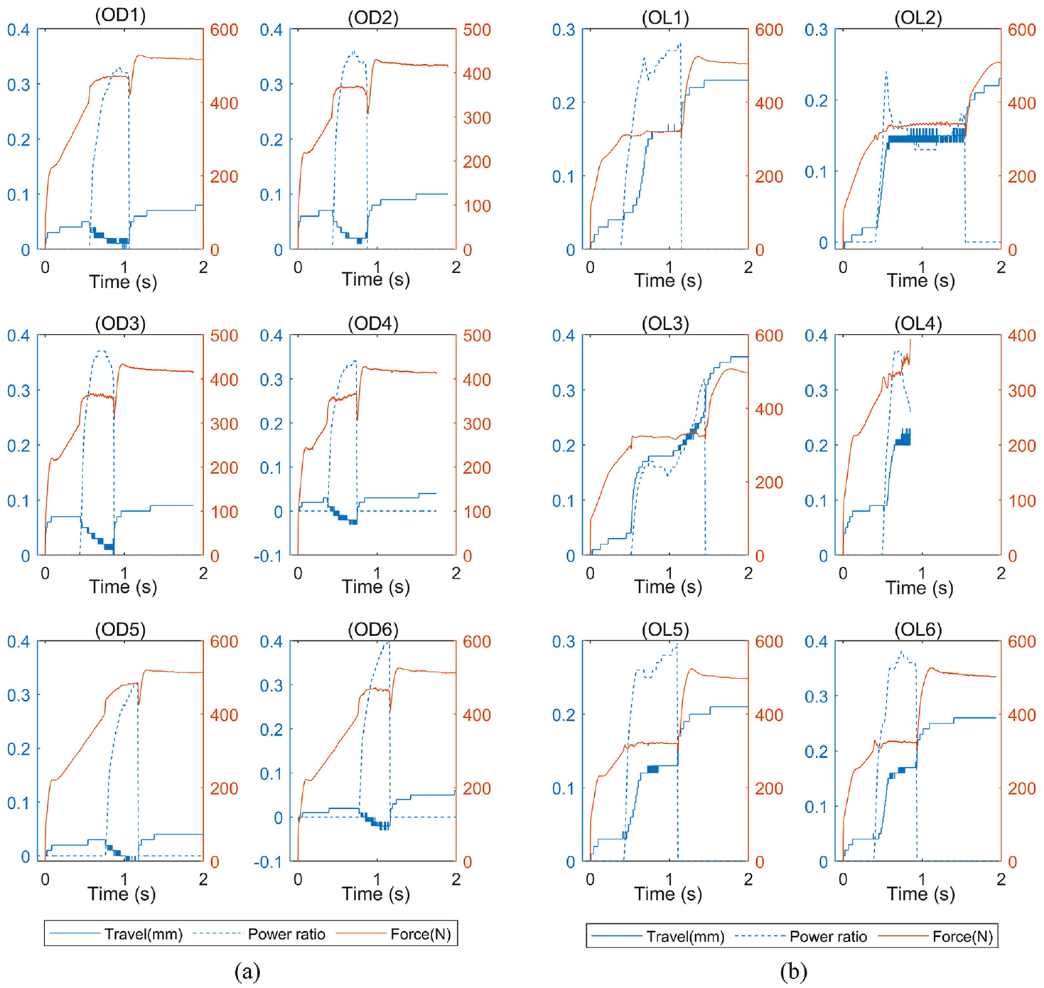
UW machine welding monitoring parameters for (a) UW DuraAct™ integrated AUCT ODi coupons, and (b) UW GF/LM-PAEK integrated OLi coupons.
The key distinction between the two design configurations is that the reaction force and thickness of the welded system increase during the welding of the ODi coupons, with an abrupt end when the welding power is released. On OLi coupons, however, the system decreases its thickness during all welding processes due to the melting of the ED and the embedment composite. This expansion effect is consistent across all ODi coupons, with a 0.05 mm expansion during the welding phase. The absolute movement for ODi coupons during welding ranges from roughly 0.08–0.1 mm for the first three coupons to 0.04–0.06 mm for the remaining coupons, representing 40%–100% of the ED thickness. The travel for OLi coupons is between 0.21 and 0.26 mm, comprising 70%–87% of the ED thickness. OL3 is an exception, with a displacement of 0.37 mm, probably due to transducer rotation.
Power behavior in all ODi coupons is similar, growing until reaching a maximum peak and then dropping. However, this is not the case with OLi specimens, where the power exhibits two peaks: the first with a large displacement followed by another peak with a smaller displacement. The lack of data on OL4 after 1 s is due to the abrupt stop of the welding.
The heat distribution throughout the overall welding process in the system section is visualized through the thermography monitoring. For data analysis, a cropped portion of the section zone between the horn and the upper surface of the CFRTP coupon is taken into consideration. During the initial welding step, thermograms exhibit a distinct AUCT edge; however, in some specimens, material squeezed from the ED obstructs the edge view after the welding process begins. In Figure 6, the heat distribution of the cropped area is depicted, where the maximum temperature is observed spatially and temporally over frames.
In ODi specimens (Figure 6(a)), two recurrent hot zones appear in the location of the piezoceramic and the electric contacts. It is possible that the different stiffness of the AUCT zones affects the generated heat. In OLi specimens (Figure 6(b)), heat distribution is not homogeneous in any of the samples, and it is mostly distributed with hot spots along the AUCT length due to the squeezed ED net. The distribution of heat indicates that in both configurations, it is not concentrated in the ED but relatively along the thickness of the AUCT.
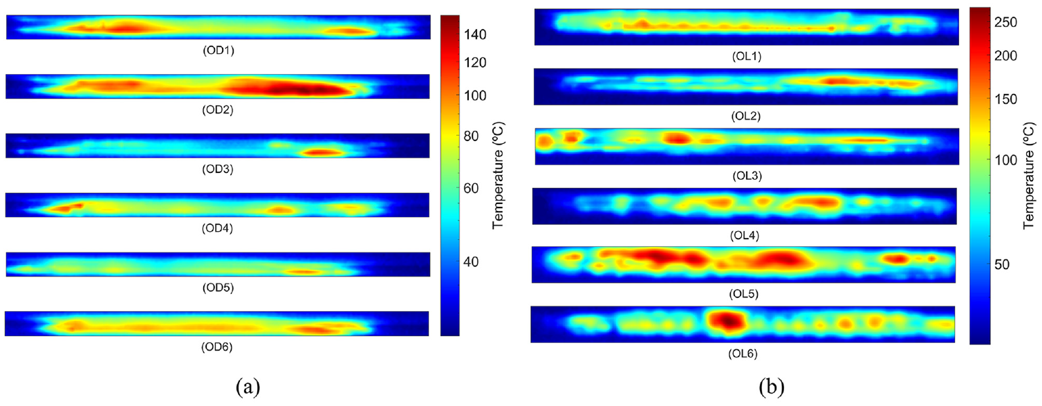
Maximum temperature thermography image frame of the cropped cross-sectional view of each (a) UW DuraAct™ integrated AUCT ODi coupons and (b) UW GF/LM-PAEK integrated OLi coupons.
The average and maximum temperatures of the cropped area during the welding process are plotted in Figure 7, where most specimens show matching average and maximum temperature peaks. The heating process lasts approximately in 0.5–1 s, followed by a consolidation phase of 1 s, after which the horn is removed. When the horn is removed, a drop-in temperature can be observed. Due to a hot ED spot that moves and appears from behind on specimen OL3, the maximum temperature rises rather than decreases after removing the horn. Maximum temperatures vary between 110°C and 160°C for ODi specimens and between 180°C and 280°C for OLi specimens. However, in any case, no temperatures exceeding the degradation or melting temperature of the AUCT are observed. The maximum temperature difference between ODi and OLi specimens is noticeable, despite the fact that the parameter set is similar. One of the reasons is a slight increase in power, but the temperature difference is also caused by differences in the EDs’ shape and thickness, stiffness, and thermal behavior of the material.19,26,27
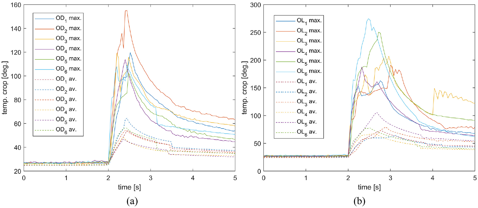
Maximum and average temperature of cropped area during the welding process for (a) UW DuraAct™ODi coupons and (b) UW GF/LM-PAEK OLi coupons.
Join characterization
The EMI of the AUCTs is measured and compared with a free AUCT, as well as with a vacuum bagging oven-integrated AUCT of each type, serving as a reference. Since the resonances of bonded transducers are higher than those of free transducers due to the coupled vibration system of the structure and transducer, EMI can be used to determine the coupling grade between the transducer and the structure. Additionally, since piezoceramic behaves as a pure capacitor out of resonance range, transducer health can be estimated from the impedance value.
From Figure 8(a), it is evident that OD1 and OD2 did not survive the welding process, as their impedance values are 0 over the entire frequency range. On the other hand, ODi coupons show that the first resonance frequency is between the free DuraAct™ and the fully bonded vacuum bagging oven-integrated reference system, indicating partial or incomplete bonding.
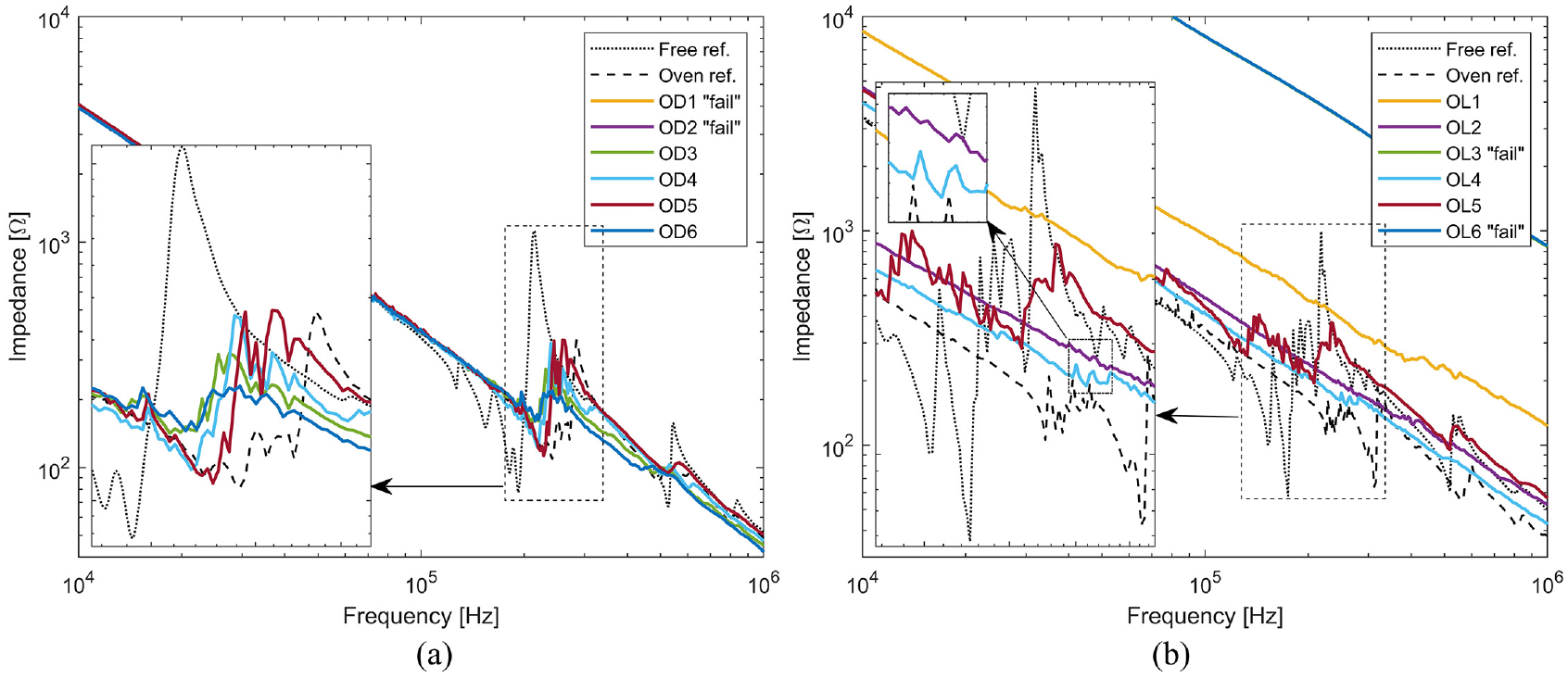
EMI measurement for (a) DuraAct™ AUCT ODi coupons and (b) GF/LM-PAEK AUCT OLi coupons.
From Figure 8(b), it is observed that OL3 and OL6 had a short circuit since their impedance is one order of magnitude higher than the reference systems. OL1 also exhibits some survivability problems, with its impedance being more than 2.5 times the reference system values. OL5 has the first resonance frequency close to the free transducer, most probably due to poor welding joint quality. Finally, OL2 and OL4 present a first resonance frequency higher than the oven reference, most likely because they are attached directly to the composite coupon without any softer interface like the reference PU22.100.
In addition to the EMI measurements, visual inspection and C-scan are performed on the specimens and compared to the reference system to identify any discontinuity in the interface or in the AUCT laminate. When observing the reference system, since the epoxy embedment is translucent, some of the background can be sensed out of the piezoceramic and electrical system zones, changing the color of the AUCT and making it slightly darker. The C-scan shown in Figure 9 illustrates low dispersion of signal with approximately −2 dB in the polymer lay-up compared to the CFRTP. The piezoceramic has a slightly higher value of around −5 dB in comparison to the coupon’s CFRTP, and the electric contacts have a value of around −11 dB. Furthermore, the AUCT’s edges have a −8 dB effect on the signal relative to the CFRTP.
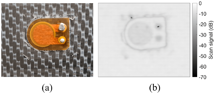
(a) Vacuum bagging oven-integrated DuraAct™ AUCT and (b) the corresponding C-scan.
In the case of ODi specimens, as shown in Figure 10, when visually inspecting the change of color out of the piezoceramic and electrical zones, it is not homogeneous, exhibiting some darker and lighter regions that match the C-scan values. OD1, OD2, and OD3 display the left bottom part of the AUCT burned and some visual damage that also corresponds with lower values on the C-scan. The C-scan on electric contacts only matches with the reference system in OD1 and OD6, while all the others exhibit some discontinuity either in the AUCT interface or in the metal-polymer contact region. Except for OD5, all other specimens show a slightly lower signal value on the piezoceramic than the reference system. In general, the region with the electrical contacts outside of the piezoceramic appears to be the most affected part of the welding process, according to the C-scan. This could be due to the non-uniform distribution of heat, with a more focused impact on the piezoceramic region due to its higher stiffness.
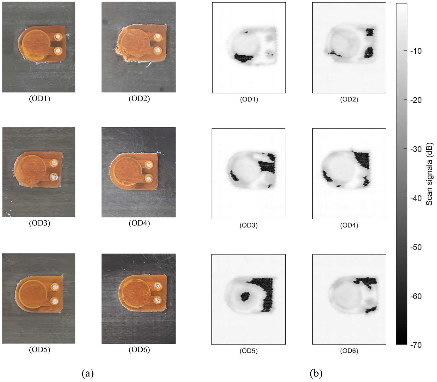
(a) ODi UW integrated DuraAct™ AUCTs and (b) the corresponding C-scans.
When visually observing and analyzing the C-scan data of the OLi specimens shown in Figure 11, a variety of effects can be noted. The first noticeable problem faced during the welding integration is the rotation of the AUCTs on OL2 and OL3. The improper fixation of the AUCT within the anvil and the CFRTP because of the impossibility of clamping due to a greater area of the horn compared to the AUCT causes the AUCTs to shift as a result of the horn ultrasonic vibration. This effect may be magnified in the case of the GF/LM-PAEK AUCTs due to the low initial surface friction area of the ED net shape and its thickness. A possible solution would be to add some removable appendices to the AUCT out of the horn area, allowing to mechanically clamp it together with the CFRTP.
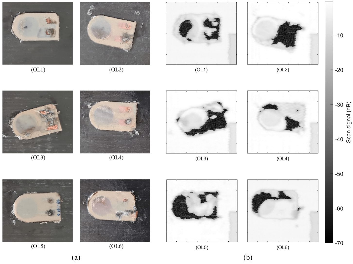
(a) OLi UW integrated GF/LM-PAEK AUCTs and (b) the corresponding C-scans.
Second, a non-uniform bonding distribution in the contact region can be seen across all specimens. Taking a closer look at OL4, C-scan values denote acceptable welding in the left bottom region, while values on the top right jump following the net fabric of the ED, indicating that the welding has not completely melted it. This effect is repeated in other specimens and indicates that the welding pressure or energy is not uniformly distributed most likely due to the different stiffness regions of the AUCT and movements during the procedure. Also, as with in ODi specimens, the regions where the cooper laminas for the electrical contact are placed have a significant gap in the C-scan values when compared to the reference system, probably for the same reason. To improve heat homogenization and pressure distribution during UW, one solution could be to modify the AUCT design and use horns with different shapes in accordance with piezoceramics stiffness region, while keeping the electrical contacts out of the welding zone.
Finally, on top of the piezoceramic zones, some dry regions can be observed where the GF is visible and the C-scan signal is lower than the adjacent ones, like in OL1 left part or OL6 left top part. Since GF/LM-PAEK is not translucent, observations cannot be made regarding the bonded regions in this case.
SHM performance
For the SHM performance evaluation, a preliminary visual inspection and EMI measurement for all AUCTs are conducted to assess the AUCTs’ health and joint quality. Integrated AUCTs in the panel are shown in Figure 12, where it is clearly visible that AUCT-5 exhibits some burned areas where the GF is visible, which is also happening in AUCT-1 to a lesser extent. On AUCT-3 and 7, since the epoxy embedment is translucid, some of the background can be sensed. In contrast, in AUCT-2, there are just a few zones that can be sensed, and none in AUCT-6, indicating poor joint quality.
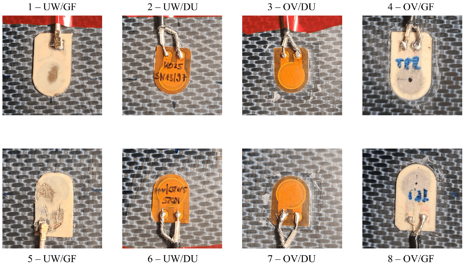
GW-SHM performance panel integrated AUCTs.
Figure 13 illustrates the EMI response in the frequency range of the first and second resonance frequencies of the system for all integrated AUCTs compared to a free AUCT of each type. In contrast to the reference vacuum bagging oven integrated AUCTs that have a higher first resonance frequency as well as a lower impedance amplitude, the welded DuraAct™ exhibits a clearly visible first resonance frequency and impedance amplitude closer to the free AUCT, indicating poor joint quality. When examining the GF/LM-PAEK, the AUCT-5 is clearly out of range, meaning that there is short circuit. The rest of the GF/LM-PAEK AUCTs have a significantly lower impedance amplitude and slightly higher resonance frequency compared to the free AUCT, indicating a decent joint quality.
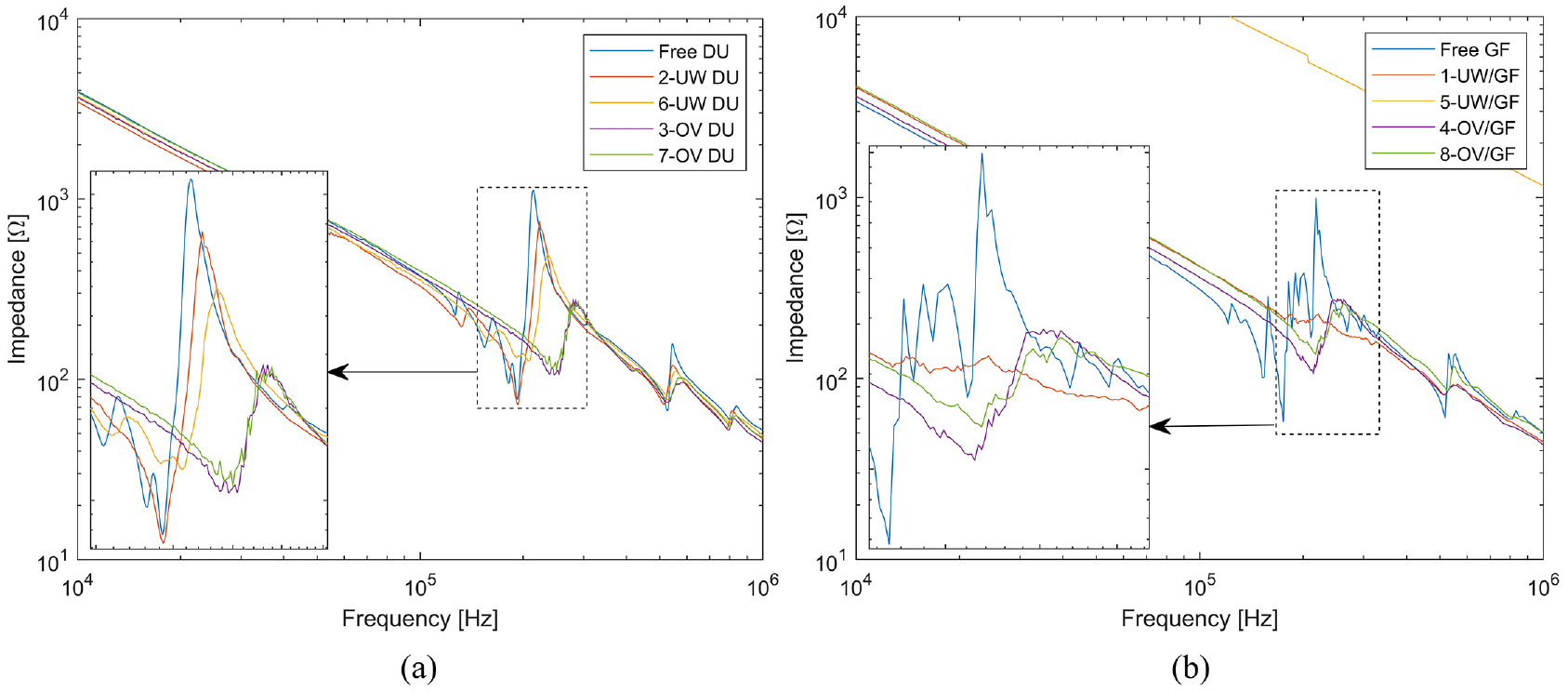
Plate EMI measurement for (a) DuraAct™ AUCTs and (b) GF/LM-PAEK AUCTs.
An actuation signal of a 5-pulse sine wave with a Hanning window and an amplitude of 5 V, amplified by a factor of 10, is triggered in all eight AUCT configurations, while sensing with the others is used for the performance evaluation. The frequency varies from 20 to 300 kHz in 10 kHz steps in order to assess wave transmission in the most common frequency range for GW-SHM. The sensing signal is further processed by denoising and finding its envelope and envelope peaks, as shown in Figure 14(a). Using the signal emitted by AUCT 1 and sensed by AUCT 3 and 4, the S0 and A0 mode group velocity (Cg) is estimated by dividing the distance from the sensors 3 and 4 (100 mm) by the measured time between the arrival of the two peaks with maximum amplitude for all frequency ranges. The empirical group velocity approximation is only used in the study to find the maximum amplitude of the primary modes during signal processing because comparison with theoretical velocities estimation requires extensive material characterization. When plotting the data in Figure 14(b), a significant increase is observed at 130 kHz, where the amplitude of the S0 mode exceeds that of the A0 mode, enabling differentiation between each group velocity.
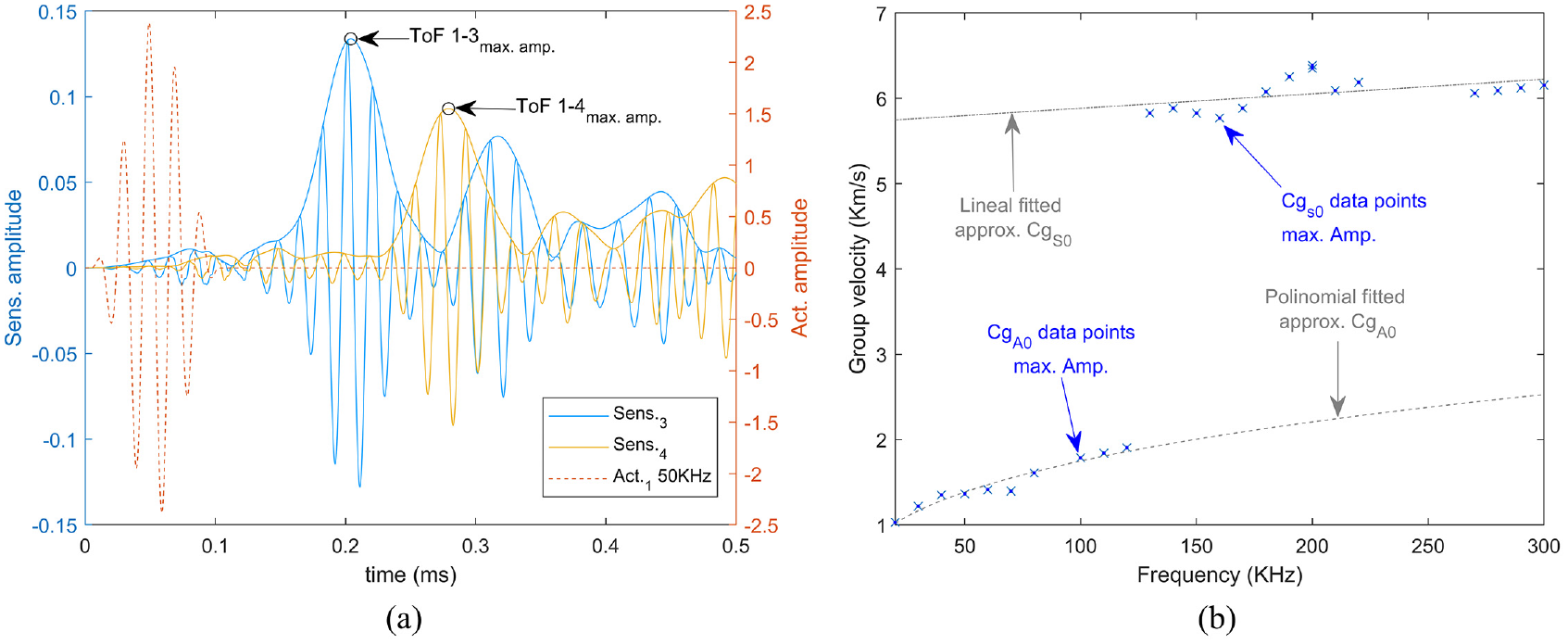
(a) Trigger and postprocessed sensing signals from AUCT-1 to AUCT-3 and 4, respectively, and (b) estimated group velocity for S0 and A0 modes.
Utilizing this information, the maximum amplitude over the frequency range is calculated for each path between equal sensor configurations. Given the failure of AUCT-5 as indicated by the EMI results, the path between AUCT-1 and -5 is replaced by the path between AUCT-1 and -4, and although they are integrated using different strategies, the AUCT and the distance remain the same as in the initial planed configuration. The propagation of the signal on the changed path is also influenced by some other factors, such as reflections or mode change brought on by transducers positioned in the path or by the closer plate edges. However, the expected influence of the change is deemed tiny for the primary excited mode of each path used for the performance comparison.
In ideal cases, the maximum amplitude of both modes occurs when the transducer diameter (2a) matches half of the wavelength (λ), and is zero when the diameter is equal to the wavelength, as depicted in Figure 15(a). In reality, the piezoceramic transducer is coupled to the structure with the embedment and joint interface, which produces incomplete transmission of stresses. This effect, also known as shear-lag, depends on the thickness and mechanical properties of the interface between the structure and the piezoceramic. 28 Stiffer and thinner interfaces reduce the effect, while thicker and softer interfaces increase it.
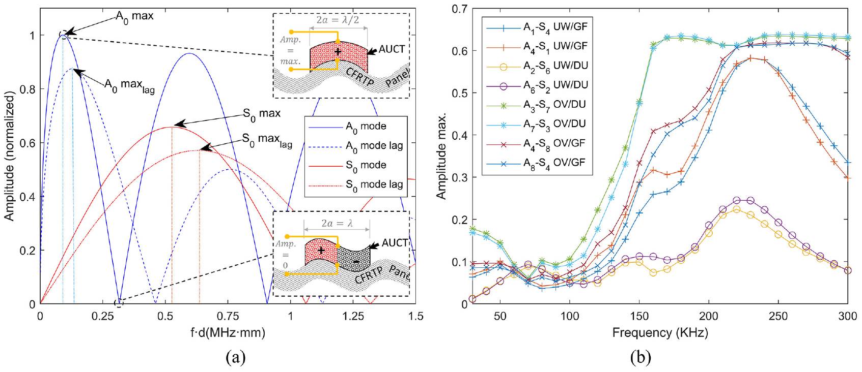
(a) Example of carbon fiber-reinforced plastic theoretical amplitudes for A0 and S0 modes over frequency range with and without lag effect and (b) maximum amplitude over frequency range for different AUCT paths.
The shear-lag together with the bonding properties affects the wave propagation and acquisition through the bonding interface, 29 and consequently it is different for the different integration methods and resulting bonding qualities. Shear-lag decreases the effective length of the transducer and, in consequence, shifts the maximum amplitude of the modes toward higher frequencies with smaller wavelengths, concurrently decreasing the amplitude. Additionally, incomplete bonding of the transducer decreases the effective length with the consequent shift. This effect, together with the EMI, aids in identifying the joint quality.
Figure 15(b) displays maximum amplitudes across the frequency range. Focusing on the lower frequency range where the A0 mode is dominant (0–100 kHz), the reference configurations (3–7 and 7–3) exhibit the maximum amplitude at 30 kHz, while the UW GF/LM-PAEK has it at 50 kHz. The vacuum bagging oven integrated GF/LM-PAEK shows the maximum at 40 kHz but with similar values at 30 and 50 kHz without a sharp peak. In the case of the UW DuraAct™, and following the results from the EMI, a clear maximum appears at 70 kHz, denoting a poor bonding interface. Regarding the amplitudes, all proposed configurations have an A0 maximum around half of the reference system. The difference between the reference vacuum bagging oven DuraAct™ and GF/LM-PAEK might be due to the AUCT construction materials and residual stresses, where the expected higher pre-compressions of GF/LM-PAEK might restrain the piezoceramic movement and consequently decrease the acquired amplitudes.
In the overall frequency spectrum, all configurations follow similar behavior except for the UW-integrated DuraAct™ (2 and 6). Consistent with the results from the EMI measurements and the frequency of the maximum amplitude in the A0 mode, which indicates a poorly welded interface, amplitudes are significantly lower, especially in the mid- and high-analyzed frequency range (130–300 kHz). In case of the S0 mode dominant frequency range, since in this frequency range the effect of the first resonance frequency plays a greater role than the lag effects, no significant shifts can be noticed.
Conclusion
The study highlights the challenges of integrating AUCTs onto CFRTP structures through UW. Despite the difficulties, the research serves as a promising starting point for an alternative approach to current solutions in developing new integration methods and AUCT designs for effective SHM networks. The UW integration method, despite the challenges, confirms the expectations to be a fast and automatable process with small infrastructure in comparison with other methods such as oven vacuum bagging where surface integration are tedious and time-consuming, with the requirement of complex infrastructure, especially for bigger parts.
The innovative AUCT design in the study demonstrates successful fiber and piezoceramic embedment into the thermoplastic matrix. Notably, the new concept shows potential benefits such as theoretically higher pre-compression of the piezoceramic, enhancing reliability under tensile and fatigue loads compared to existing market-available AUCTs. However, the research indicates that integrating AUCTs via UW faces reliability challenges when it comes to changing the materials of the AUCT using the same design principles as DuraAct™ without rethinking the entire concept. The assumption of achieving higher pre-compressions with very low fiber content appears ineffective for UW, requiring a reconsideration of design principles. Challenges include the need for higher fiber content for successful energy focusing in the ED and the optimization of AUCT geometry and electrical contact arrangement for the UW process.
Process monitoring tools identified successful welding in certain regions of the AUCTs, but challenges remain in obtaining a clear picture of heat distribution during the welding process. Characterization techniques, including EMI, C-scan, and GWs, proved effective in identifying integration flaws and electrical issues. EMI has proven to be a fast and reliable method not only to identify flaws in the join but also electrical issues. The study emphasizes the need for further work to optimize welding parameters, enhance heat homogenization, and improve pressure distribution during UW. Additional tools, such as thermocouples and advanced thermography systems, could contribute to a comprehensive understanding of heat distribution. Differential scanning calorimetry tests can also be employed to identify the heat affection zone and the possible impact of the AUCT integration onto the structure.
In conclusion, the tested SHM network demonstrated that UW is a viable solution for fast AUCT integration, particularly for the newly designed GF/LM-PAEK. The latter seamlessly interfaces with the structure matrix without creating dissimilar material interfaces. While there is room for improvement in GW amplitudes, the study suggests that differences in performance compared to DuraAct™ may stem from transducer construction rather than the integration method.
Footnotes
Author contributions
Declaration of conflicting interests
The author(s) declared no potential conflicts of interest with respect to the research, authorship, and/or publication of this article.
Funding
The author(s) disclosed receipt of the following financial support for the research, authorship, and/or publication of this article: This project has received funding from the European Union’s Horizon 2020 research and innovation programme under the Marie Sklodowska-Curie grant agreement no. 859957 “ENHAnCE, European training Network in intelligent prognostics and Health mAnagement in Composite structurEs.”