
Abstract
Aerodynamic and aeroacoustic performance experiments were carried out on four- and eight bladed, 1.542 m diameter, axial flow cooling fans, with constant solidity and hub-to-tip ratio. Tests were conducted in an ISO5801, Type A Fan Test facility. The tip gap (TG) was reduced from 4 mm (0.26% fan diameter) to 2 mm (0.13% fan diameter), to 0 mm, for both fan configurations. The noise profile of each fan configuration at the same TG over the whole volumetric flow rate spectrum was compared to each other. The 4 mm (0.26%) TG is used as a baseline to measure the nett increase or decrease in sound levels. Noise emissions decreased as the TG was reduced. It is discovered that the four bladed fan configuration had lower noise emissions than the eight bladed fan configuration at all blade tip clearances at design flow rate. It is concluded that reducing the TG and number of blades, at constant solidity, reduces sound emissions. The 0 mm TG for the four bladed fan produced the greatest reduction in noise emissions. An increase in fan total-to-static performance is observed when reducing the TG for both fan configurations.
Introduction
Thermal power stations that make use of the Rankine steam cycle, such as concentrated solar power (CSP) plants, use arrays of air-cooled condenser (ACC) units to condense the working fluid by rejecting its heat to the passing air. Each ACC unit contains heat exchanger bundles through which air is forced by large diameter axial flow fans. 1 These rotor-only fans have no nose cone, rotor-straighteners, or guide vanes, and can be as large as 12 m in diameter per fan. 2 Studies indicate that these axial flow fans are significant contributors towards noise emissions at thermal power stations, with measured average noise emission intensities as high as 88 dB(A).3,4
The intensity with which noise is emitted from an axial flow fan is dependent on the rotational speed, number of blades and geometric shape of the blades. Large diameter axial flow fans are predominately low frequency noise emitters due to the sheer size of the blades and lower rotational speeds. Low frequency noise can travel greater distances and penetrate nearby houses and buildings and poses a greater concern towards human quality of life than high frequency noise. 3 Kugler et al. 5 showed that exposure to seemingly unobtrusive low frequency noise (<250 Hz), at 80 dB(A) for 90s, affects the micro-mechanics of the human ear for up to 2 min after exposure.
Numerous attempts to reduce ACC noise emissions in thermal power plants have been made, mostly by adding silencers to the ACC units. These methods have proved detrimental to the electrical output of the power plant as the system efficiency is decreased due to ACC inflow conditions being distorted. 3 Focus has therefore shifted towards the redesign or modification of axial flow fan blades. Van der Spek 6 found that increasing the chord length and reducing the rotational speed of the fan, in order to maintain performance through constant solidity (Eq. (1)), resulted in a reduction of noise emission intensity. To further reduce noise emission intensity, it is advantages to add blade sweep to the blade profile. This type of fan achieved a 15 dB(A) decrease in noise emission intensity.
Unfortunately, to manufacture such a low noise fan costs four times higher than that of conventional straight bladed axial flow fans. 6 This has led to the development of numerous blade modifications to silence noise sources on the fan blades.7–11 Research done in silencing noise sources on large diameter axial flow cooling fans without compromising fan performance is not exhaustive. There remains therefor a need to investigate simplified noise reduction techniques that are easily appliable to existing large diameter axial flow cooling fan blades.
Industrial fan design
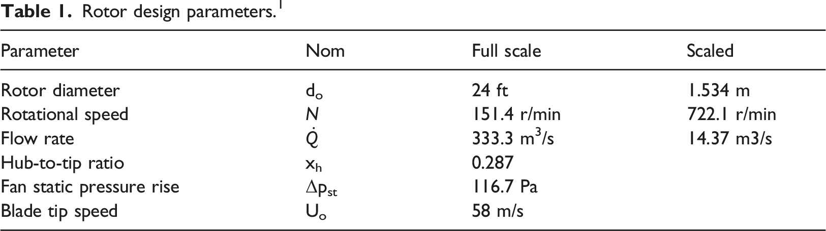
Rotor design parameters. 1
Fan noise sources
Noise is the result of flow fields experiencing a spatially non-uniform distribution, that causes an unsteady response of the resulting periodic pressure pulses due to the acting lift and drag forces on the fan blades. The noise radiation frequency corresponds to the blade-passing frequency (BPF) and is radiated with high aeroacoustic efficiency. 13 The BPF is dependent on the rotational speed and is therefore perceived as a low frequency sound.
Human perception of sound intensity is different to that of physically measuring sound intensity (dB). Humans perceive sounds well between 1 kHz and 6 kHz but have reduced perception outside of this bandwidth. 14 To represent the human perception of sound in numerical terms the sound intensity level (dB) is given a weight distribution over the spectrum known as A-weighting (dB(A)). 14 Therefore, impeller design should take into consideration the effect of BPF and its harmonics. The closer the impeller’ BPF is to the 1 – 6 kHz bandwidth the more likely the effect of the BPF will be perceived by humans.
One method of reducing the BPF is to reduce the number of blades at constant RPM and volumetric flow rate, and thus necessitates a scaled chord length using constant solidity ratio as defined by equation (1)6,15
This is applied to the eight bladed M-fan in this study. The number of blades is halved and the chord length doubled to keep the solidity of the fan the same, thus keeping the design point parameters of the four bladed M-fan the same as that of the eight bladed M-fan. All other parameters are kept constant.
A dominant noise source found in large diameter axial flow fans is tip leakage noise or tip clearance noise.16,17 Tip clearance noise is the byproduct of vortices that form due to the high-pressure air leaking around the blade tips. 18 These tip leakage vortices are ingested by the rotor, due to the reverse flow nature of these vortices, and can contribute significantly towards turbulence ingestion noise or leading-edge noise.16,19 Turbulence ingestion noise can be countered through adding leading edge serrations to the blades.9,20 These serrations act as vortex generators and reduces noise generation through destructive interference. 9 Biedermann 9 and Becker 20 found that decreasing the leading-edge serration wavelength and increasing the serration amplitude resulted in a reduction of noise emissions.
The use of blade tip modifications to control the formation of tip clearance vortices have been proposed by Corsini et al. 21 Milavec et al. 11 and Meyer 22 with Milavec et al. achieving a maximum noise reduction of 8.6 dB(A) with their blade tip modification. Study conducted by Wilkinson and van der Spuy 23 concluded that fan performance is improved by the addition of fan blade end plates but not to the extend as decreasing the blade tip clearance. In the case where tip leakage vortices lead to leading-edge noise, the size of the vortical structures around the blade tips can be reduced by reducing the blade tip clearance.16,18,21 Therefor it would be beneficial to reduce the blade tip clearance and investigate the effect of a zero mm blade tip clearance on the aerodynamic and aeroacoustic performance of a large diameter axial flow cooling fan such as the M-fan.
Experimental setup
All tests were conducted in the large fan test facility at the Department of Mechanical and Mechatronic Engineering at Stellenbosch University. The Fan Test Facility is classified as an ISO 5801, Type A (free inlet, free outlet) test facility, conforming to the standards prescribed in ISO 5801.
24
Details on the design and commissioning of the facility is described by Venter.
25
The main features (also indicated on Figure 1 below) of the fan test facility adapted from Augustyn
27
and Louw
26
are: 1. A calibrated bellmouth inlet ( 2. A louvre unit (throttle unit) with flow straighteners which is used to manually adjust the volumetric flow rate through the facility. 3. An 11 kW, six blade auxiliary fan is used to overcome pressure losses in the system. The auxiliary fan is powered by a variable speed drive (VSD). This was also used in conjunction with the louvres to adjust the flow rate. 4. A flow straightener to remove flow disturbances due to the auxiliary fan. 5. The plenum chamber (6) includes guide vanes and three mesh screens of increasing fineness to correct the flow and ensure a uniform flow field enters the test fan. 6. The plenum/settling chamber. The plenum chamber is a 4 m high, 4 m wide by 7 m long chamber used to slow the inlet flow velocity in order that the dynamic pressure at the test fan inlet can be considered negligible if the flow velocity is less than 2 m/s. Thus, ensuring that the inlet conditions of the test fan can be considered as “open”.
24
7. The test fan with a casing diameter of 1542 mm. 8. The test fan motor unit which is covered by an anechoic material lined box to minimize noise sources from the motor. The motor power rating is 11 kW. The motor delivers the power through a belt drive to the test fan shaft. A torque transducer is located on the shaft between the belt drive pulley and test fan. ISO5801, type a fan test facility adapted from louw,
26
including microphone positions.
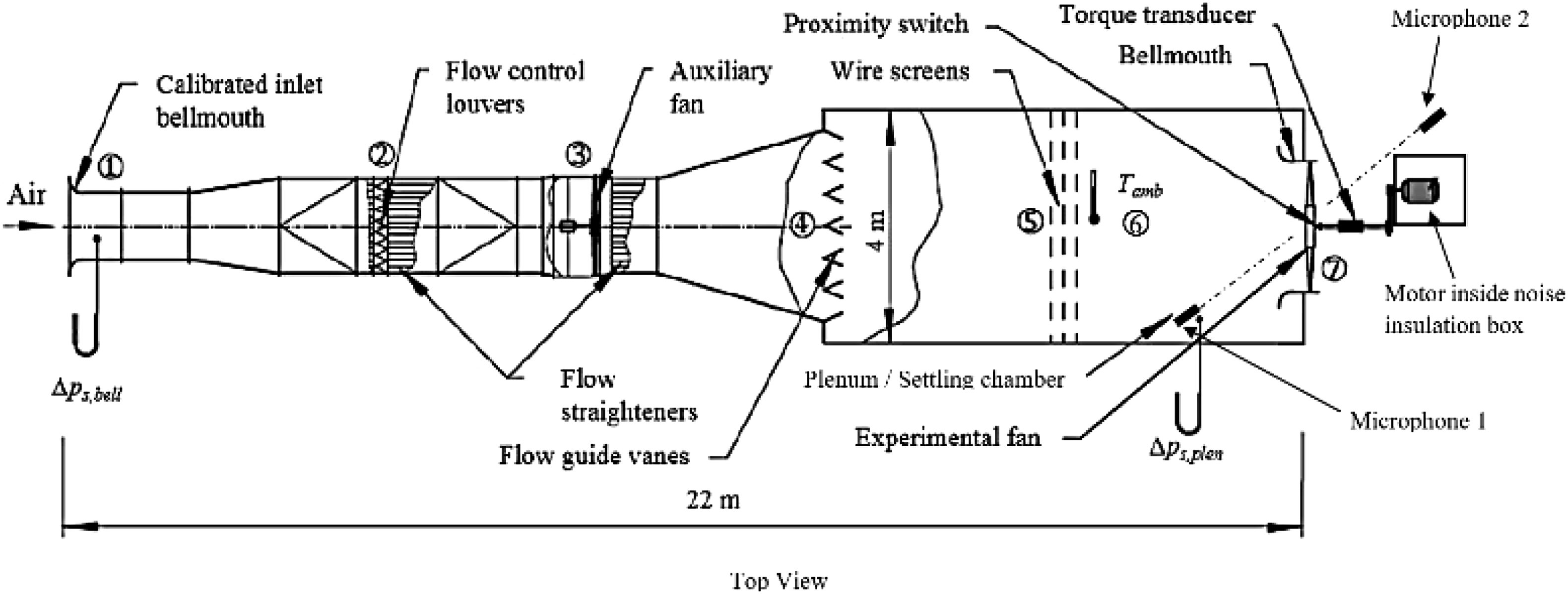
Figure 2 below displays the installed M-Fan in the fan test facility. The positions of microphones one and two are indicated in Figure 1. Microphones one and two are located at a 45° angle and two fan diameters away from the center of the rotor on both the pressure and suction side of the fan. The noise measurement equipment is discussed in Noise measurement equipment below. 1.534 m eight bladed m-fan installed in the ISO5801, type a fan test facility.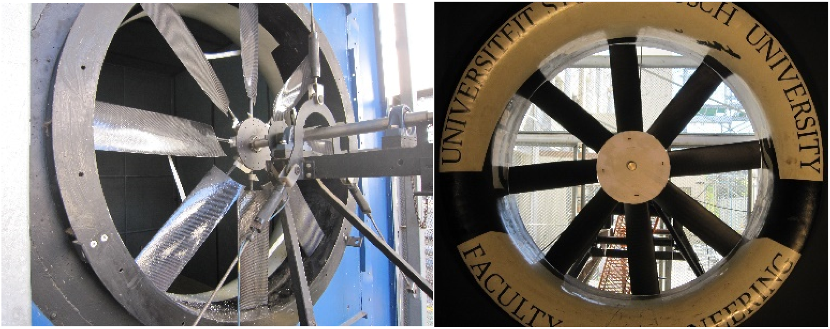
Fan test facility equipment
The instrumentation used to capture the fan performance characteristics of both the four and eight bladed M-Fans are as follow:
Pressure: Endress + Hauser Deltabar S (range: ±1000 Pa)
Torque: HBM T22 Torque Transducer with no-slip ring (100 Nm).
Speed: Turck Inductive proximity sensor (0–10 V)
DAQ: HBM PMX with PX401 and PX455 measurement modules.
Noise measurement equipment
The noise instrumentation used to capture the noise spectrum of the fans are as follows:
Microphone 1: ½” free field microphone, class 1 WS2F (DIN IEC 61,094–4).
Frequency response: 3.5 Hz–20 kHz.
Sensitivity: 50 mV/Pa.
Microphone 2: ¼” IEPE free field microphone, class 1 (IEC 61,672).
Frequency response: 20 Hz–20 kHz.
Sensitivity: 50 mV/Pa.
DAQ: two Channel NVH Analyzer Lite for IEPE sensors. 16-bit, 48 kHz simultaneous sampling rate.
Signal processing
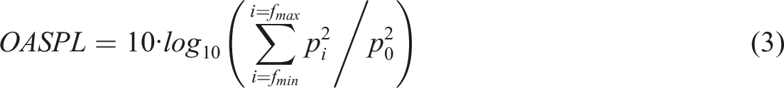
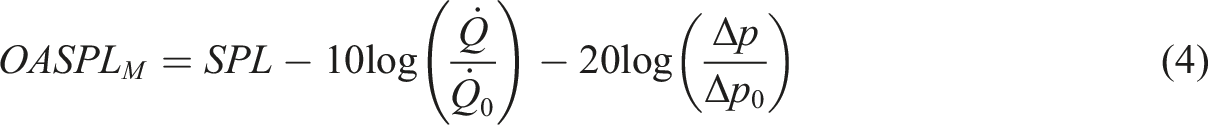
The aeroacoustic signals require an advanced pre- and post-processing strategy. The set of wall-mounted microphones is employed to gather the aeroacoustic signature of the prototypes at a sampling rate and block size of SR = BS = 32,768 (Hz), resulting in a frequency resolution of Δf = 1 Hz. Applying several 200 averages while using Hanning windowing and an overlap of 66% serves to minimise random noise effects while improving the stability and reliability of the gathered signals. The sound pressure levels (SPL) of the gathered microphone signals is obtained via equation (2) by taking the spectral data for each discrete frequency into account. Integrating or, in the time-discrete domain, summing-up the spectral levels result in the overall sound pressure levels (OASPL) as defined by equation (3) for a band-pass filtered spectral range of 10 Hz ≤ f ≤ 10 kHz. Note that the low spectral threshold of fmin = 10 Hz is chosen to incorporate the fans' first speed-dependent fundamental frequency of n = 720 r/min = 12 Hz for the current analysis as well. However, an aeroacoustic assessment of the radiated noise always requires rating both the aerodynamic and the acoustic characteristics at the same time. One way to reduce the resulting complexity of the analysis is to normalise the OASPL by the aerodynamic parameters as e.g. proposed by Madison et al.,
29
where minimum levels indicate an optimum in terms of aerodynamics and aeroacoustics (Eq. (4))
To assess the underlying aeroacoustic effects of signal differences between any baseline reference case and modified prototypes it is considered useful to separate the tonal effects of discrete frequencies from those of purely broadband character. The former can either be aligned with the rotor-speed (tip clearance effects, rotating stall) or be caused by vortical structures which rotate with a lag relative to the rotor speed (rotating instabilities, blade to blade interaction noise).
30
However, the current study focusses on the tip clearance effects, which is why a spectral filtering of a ±5 Hz frequency band around the blade passing frequency and their integer ith multiples (harmonics) is conducted (Eq. (5)). On the other hand, a one-dimensional median filter of 100th order is employed to obtain the broadband signal, neglecting all tonal effects.
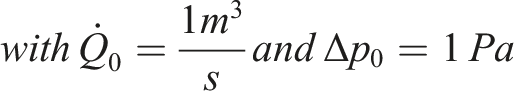
Preliminary investigations showed the blade passing frequency to be highly stable during operation. Figure 3 highlights the variance of the BPF (12 Hz–720 r/min) associated with the different fan settings under investigation. Given the maximum variance ΔfBPF ≤ 2 Hz and considering the spectral measurement resolution of Δf = 1 Hz, justifies the choice of a 5 Hz frequency band around the BPF to cover the aeroacoustic energy of these tonal artifacts. Adding-up the extracted BPF-spectra with the separated broadband spectrum yields exactly the OASPL of the initial signature. Variance of measured rpm across 12 operating points for each fan configuration.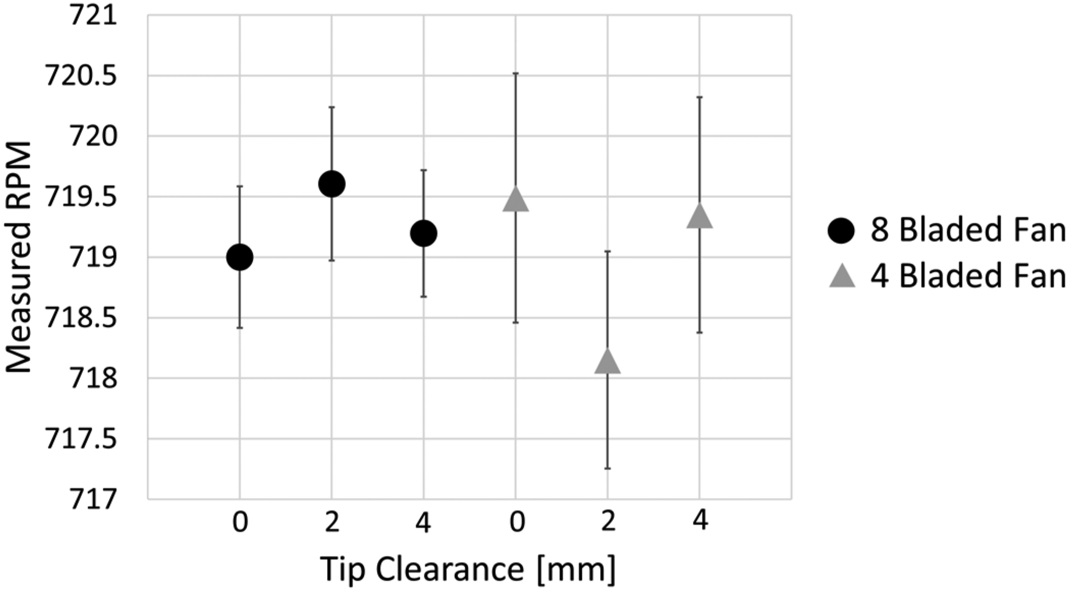
Experimental methodology
Investigations into the performance and noise characteristics of the four- and eight bladed M-fan configurations are conducted by reducing each fan’s tip gap by 2 mm increments from 4 mm to 0 mm, thus closing the tip gap completely. Noise measurements are taken throughout the performance characterization of each fan configuration to provide a thorough noise spectrum across each fan’s characteristic profile at their respective tip gaps. A box lined with anechoic material was designed to cover the motor driving the fan to eliminate unnecessary noise sources. Ambient noise levels were taken from within and outside of the plenum chamber. These ambient levels are not subtracted from the results as they are sufficiently low.
The performance curve of each fan configuration is achieved by throttling the volumetric flow rate through adjusting the auxiliary fan speed and the closing of the louvres. The inclusion of the louvres and auxiliary fan in facility allows the user to control the load (volumetric flow rate) experienced by the fan without having to adjust the blade setting angle or rotational speed of the fan. Thus, the flow rate is adjusted without adjusting the fan configuration under investigation. Whilst keeping the fan speed constant at around 720 r/min, 12 consecutive readings are taken across the performance curve of the fan. The noise generated by the test fan was masked by the auxiliary fan when switched on and running at full speed. When lowering the speed of the auxiliary fan, the noise source produced by it became negligible, but enough volume flow rate was still provided to overcome the pressure losses in the system. The microphones were kept at the same positions, aimed at the center of the rotor plane.
Aerodynamic repeatability
Aerodynamic repeatability is realized by keeping the hub position axially constant on the motor shaft. Effort is taken to ensure that blade root set angle and blade tip angle for both four- and eight bladed M-fans remained the same. Tip gap measurements were also performed before each test to ensure the tip gap remained constant with each fan configuration and was comparable to the previous configuration.
Aeroacoustic measurement conditions
In order to provide reliable data, the assessment of the acoustic measurement conditions play a key role. This is especially the case as the test chamber is located outside and hence, experiences an increased influence of the background noise, weather conditions etc. Therefore, preliminary experiments at characteristic operating conditions of the fans were conducted to monitor (a) the ambient background noise as well as (b) the influence of the driving motor (Figure 1), located outside the plenum chamber in the free-field. In the sense of a worst-case scenario Figure 4 exemplarily shows the results of the 4-bladed M-fan since this configuration has proved to be less noise compared to the 8-bladed configuration. Hence, the risk of experiencing an impairment of the acoustic fan signature by the motor noise or the environment is at its highest. Spectral composition of 4-bladed m-fan at characteristic operating conditions including ambient and motor noise. Free-field signature (top) and plenum signature (bottom) at 720 r/min.
Figure 4 shows the acoustic signature of the fan at three characteristic operation conditions at overload (Q = 13.3 m³/s), design (Q = 11.3 m³/s) and part-load (Q = 7.3 m³/s), all having operation-specific patterns due to the differences in the aerodynamic flow regimes. In addition, the motor signature at maximum fan speed as well as the ambient conditions are included. The spectral composition offers detailed insights in potentially disturbing components, not fulfilling the required signal-to-noise ratio, while the listed overall levels (OASPL) state the total differences between the depicted cases. Figure 4 (top) generally shows a satisfying distance between the ambient noise and all tested operation conditions for the entire frequency band. The motor signature primarily shows high-frequency characteristics with the highest noise levels occurring at f > 1 kHz, hence showing some potential to affect the obtained acoustic signature of the fan at frequencies corresponding to the motor-rpm and the number of coils at 3 kHz ±200 Hz, 6 kHz ±500 Hz and 9 kHz ±500 Hz. These unfavorable conditions are clearly assigned to the free-field microphone being in close proximity to the motor itself. However, in terms of the total level, the fan operates with at least 16.2 dB above the motor noise. Assessing the conditions inside the plenum chamber (Figure 4 bottom) significantly changes the measurement conditions to the better. Along the entire spectral range, a sufficient signal-to-noise ratio is obtained for the conducted measurements. Solely at 5400 Hz, 5926 Hz and 6000 Hz a slight and discrete contamination of the fan signature exists, not considered relevant for the declared purpose of this study. On the other hand, the first harmonic of the fundamental frequency at f = 24 Hz, previously been masked by the free-field environment, shows to be of similar magnitude than in the fan signature, potentially leading to reinforcement effects.
Acoustic transfer function
As it is shown in Figure 1, two microphones are employed to monitor the aeroacoustic signature of the fans under investigation. The first microphone is located inside the plenum chamber to reduce potential disturbances of the ambient noise as well as the motor signature. However, a second microphone is located outside the plenum in the free-field to serve two purposes. First, previous numerical studies on the acoustic signature of the fan analyse the derived sound pressure using a virtual monitor point at the same location.
16
Hence, the experimentally obtained data can be used for direct comparison. Second, comparing the signals between plenum chamber and free-field allows to conclude on effects such as directivity, the modal structure of the plenum but also on differences between the suction side and the pressure side of the fan. In the following sections, however, primarily the acoustic signals of the plenum chamber are analysed. Performing simultaneous measurements at both locations enables to define a transfer function, which allows for conversion of the obtained signals from Mic one to Mic 2 (Figure 1). The transfer function describes the spectral relation between e.g. a source U1 and a receiver U2 by treating potential influencing interfering signals as a black box and can be defined according to equation (6). However, for the current setup the transfer function is defined between the microphone on the fan pressure side and on the fan suction side, being mounted in the plenum chamber (see Experimental setup, Figure 1). The transfer function is therefore used to validate the results obtained from the microphone on the fan suction side within the plenum to that of the microphone on the fan pressure side in the free field.
As the measurement setup already indicates, a number of influencing parameters is varied during the measurement campaign, namely the number of fan blades, the blade tip gap and the point of operation. To define a general overview on the relationship between the plenum microphone (suction side) and the pressure side microphone in the free field, the averaged sound pressure level difference between the two sensors is depicted in Figure 5. Note that multiple transfer functions are averaged for 12 discreate operation points along the characteristic curve, ranging from overload to part-load conditions. Moreover, three different tip gaps Δz = 0 mm, 2 mm and 4 mm are incorporated as well, resulting in a characteristic transfer function for the 4-bladed and the 8-bladed M-Fan. Both fans investigated show a similar dependency on the measurement conditions, where especially at 80 Hz a significant decrease of the transfer function is observed, being due to an eigenmode of the plenum chamber. Sound pressure level difference between the pressure and suction side microphone.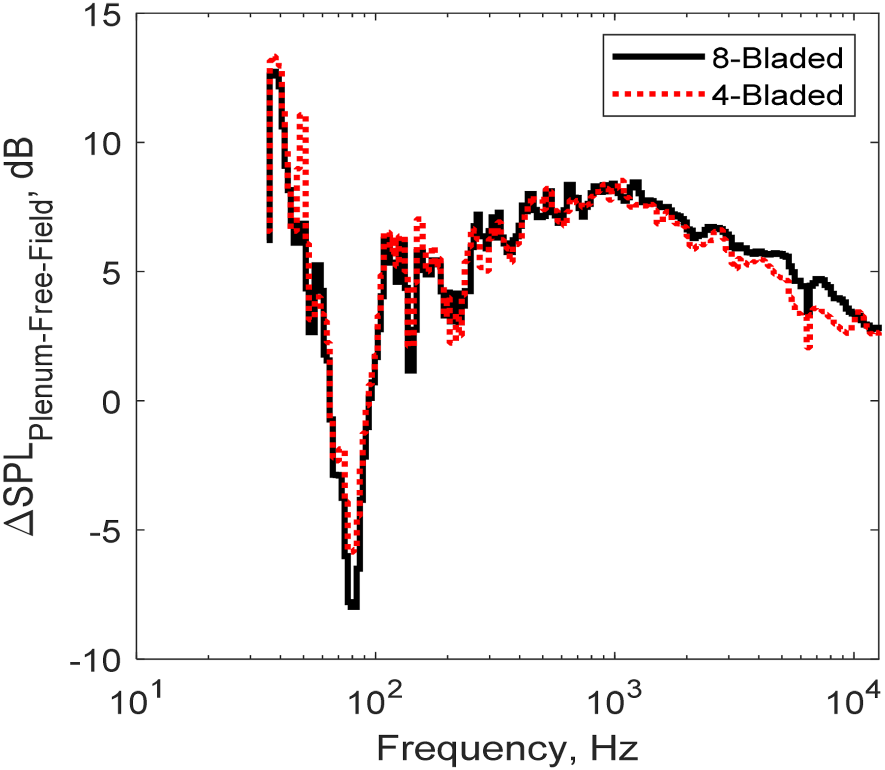
Figure 6 compares the so generated mean transfer function against local representatives at characteristic operating conditions for overload, design, and part-load of the 8-Bladed M-Fan. As can be seen the general pattern of the transfer function is maintained independently of the operating conditions even though local phenomena are poorly represented by the averaged transfer functions in Figure 5. Since no strong dependencies of the transfer function on a) the blade tip gap, b) the chosen blade number of the M-Fan or c) the point of operation is observed, the transfer function can be stated as qualitatively general. Hence, for brevity this paper is restricted to analysing the plenum chamber suction side signals, being less prone to signal masking due to high ambient noise etc. Sound pressure level difference between the pressure and suction side microphone.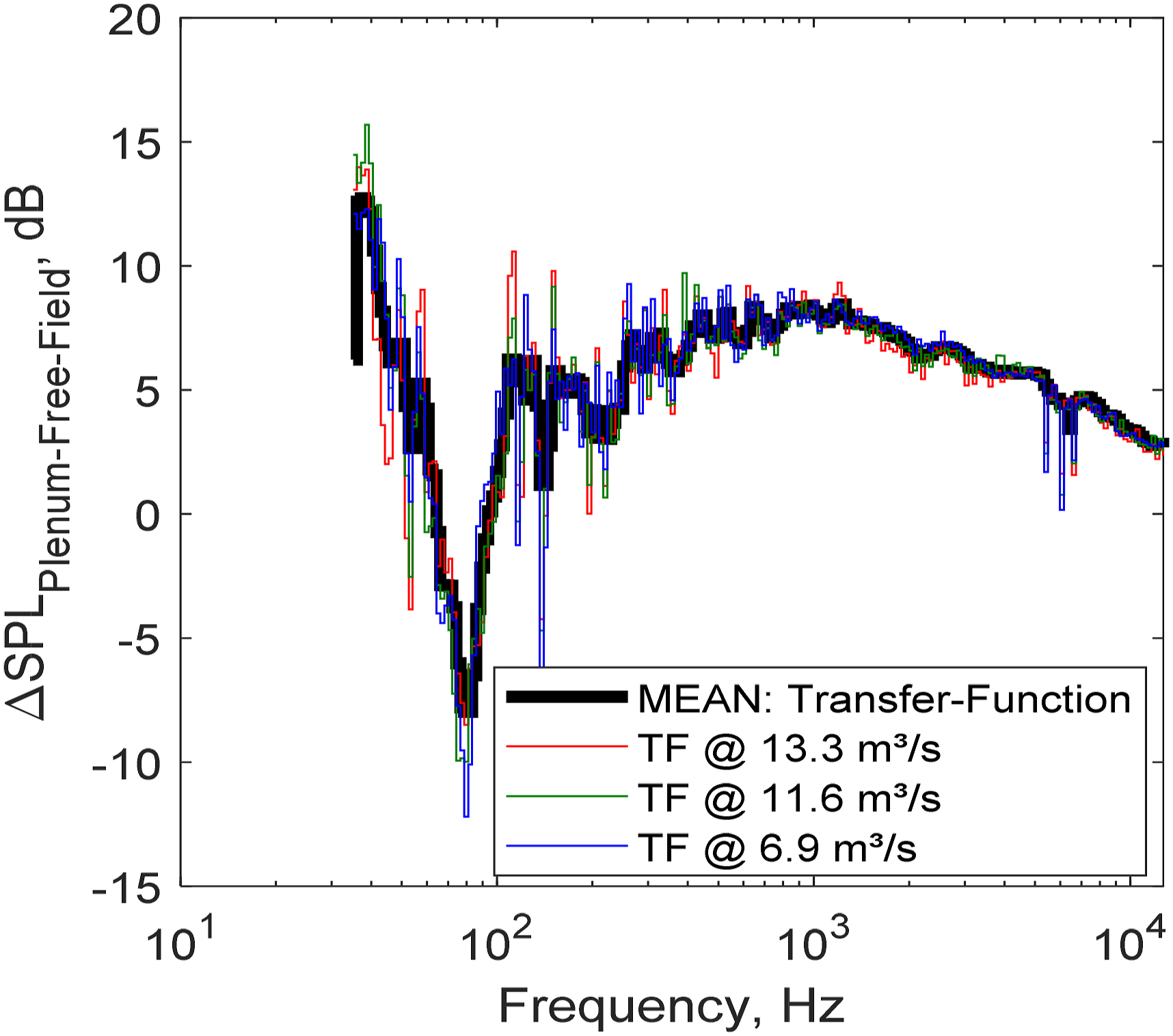
Fan blade variation
Aerodynamic performance
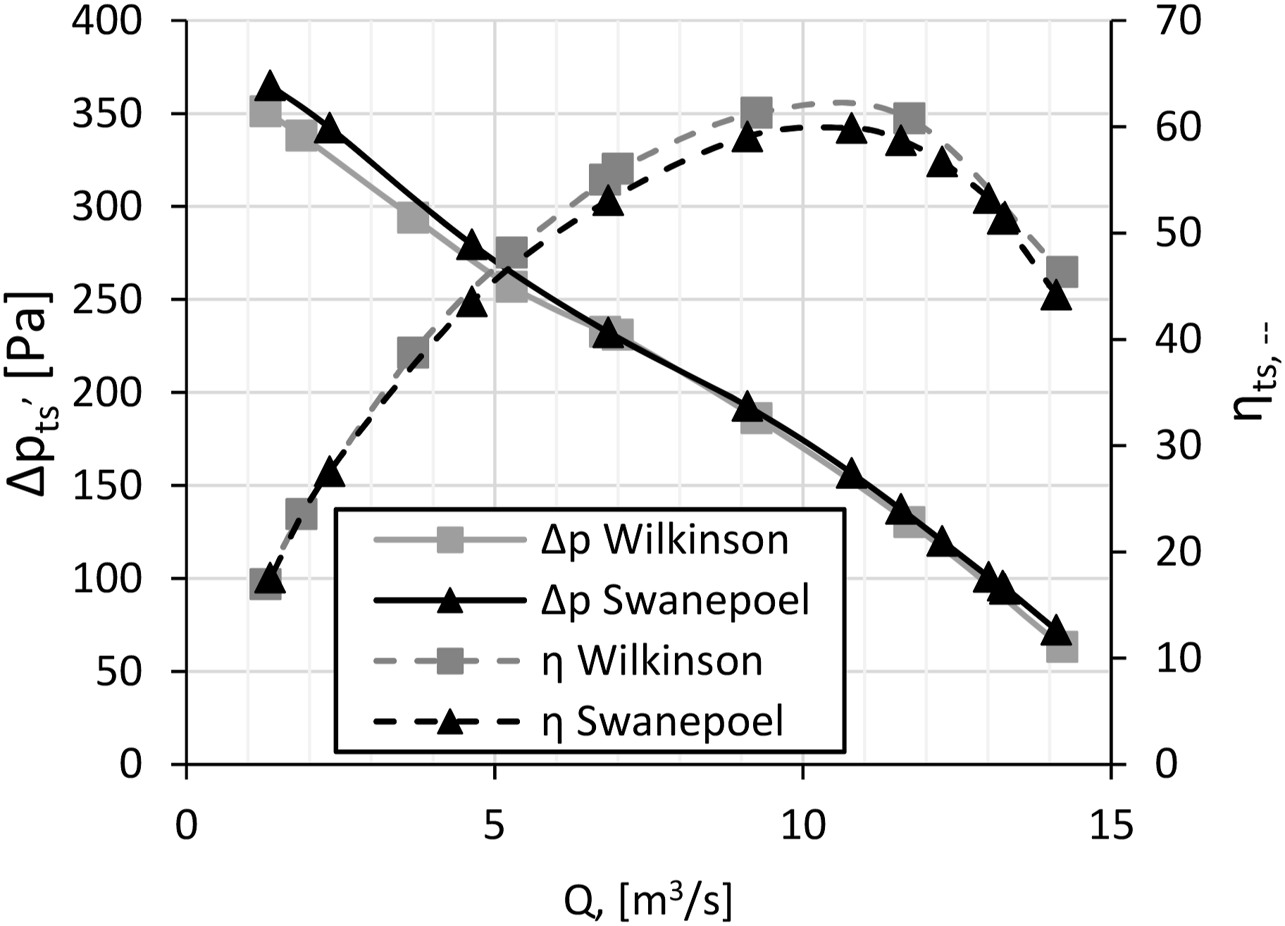
The eight bladed impeller configuration with a 0.26% tip gap, 33° blade setting angle is tested and compared to previous work done by Wilkinson et al.
1
As seen in Figure 7, the results obtained agree well with the data from Wilkinson and therefore validated the blade angle used throughout all experiments. As the aerodynamics are kept constant, except for the tip gap and chord length, the aerodynamic and aeroacoustic characteristics are evaluated relative to the largest tip gap of 0.26% fan diameter (4 mm) of each configuration. Validation of eight bladed m-fan at 33° blade set angle and 4 mm (0.26%) tip gap with wilkinson.
1
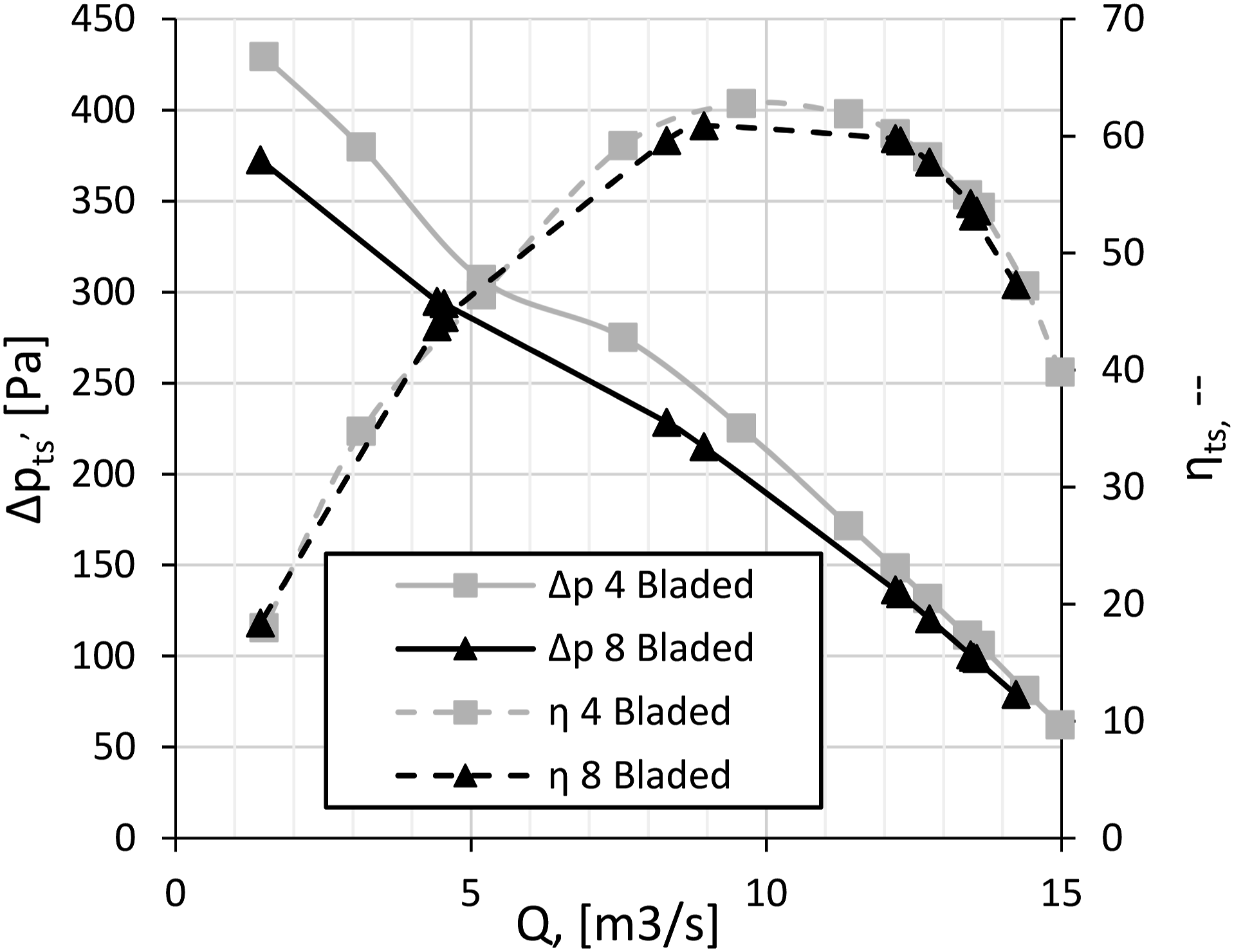
As mentioned above, two impeller configurations are tested, namely the four bladed M-fan and eight bladed M-fan. The four bladed M-fan has the exact same profile as the eight bladed M-fan but half the blades at twice the chord length. This is to keep the solidity constant but reduces the blade passing frequency (BPF) while maintaining the performance characteristic of the eight bladed M-fan at design conditions.6,15 The initial design flow rate was determined for the eight bladed M-fan at Validation of four bladed m-fan with eight bladed m-fan at 4 mm (0.26%) and 2 mm (0.13%) tip gap. Validation of four bladed m-fan with eight bladed m-fan at 0 mm (0%) tip gap.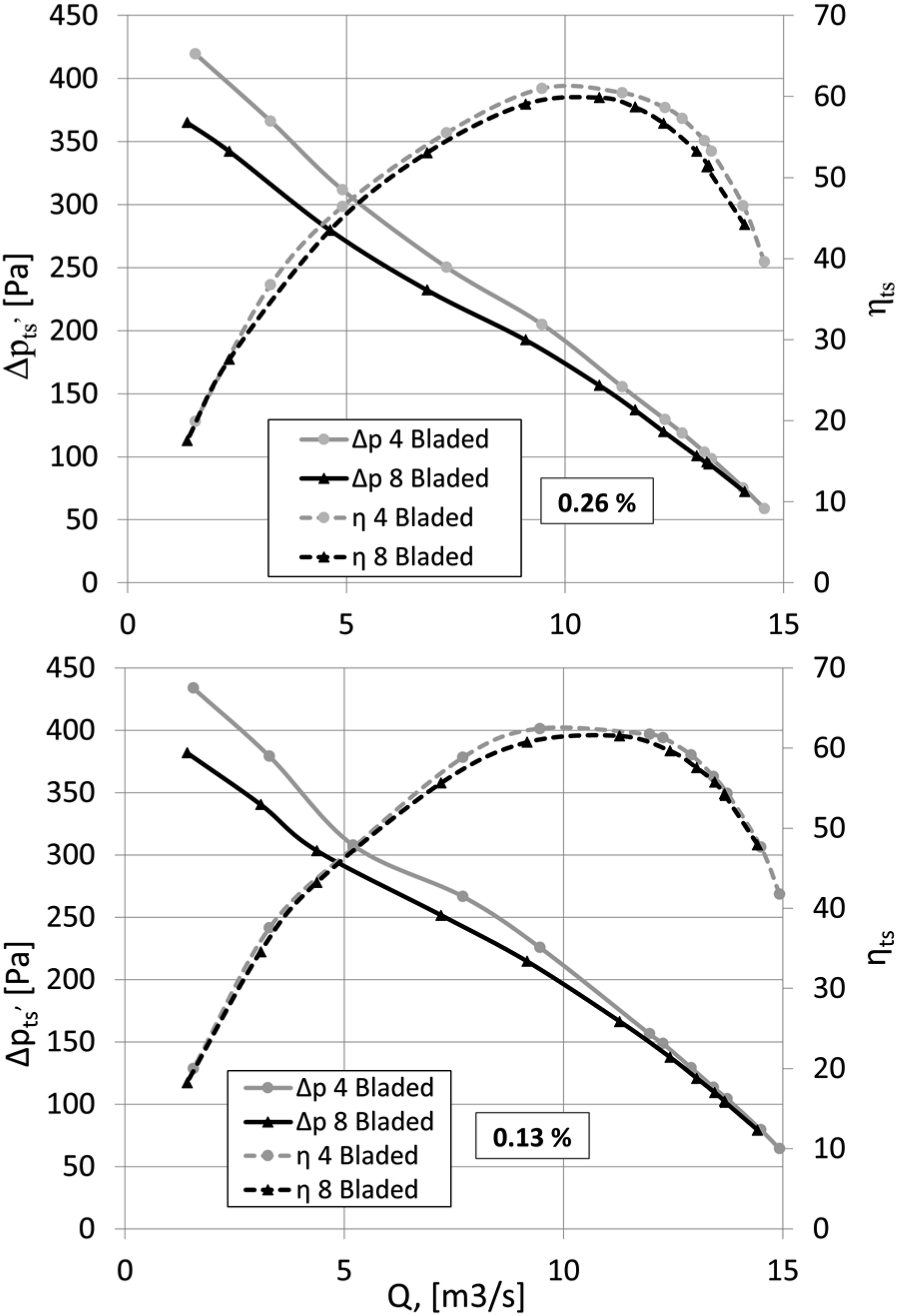
Aeroacoustic Performance
Figure 10 shows the overall sound pressure level in the frequency range 10Hz ≤ f ≤ 10 kHz along the full characteristic curve. Starting at maximum flow rates, indicating overload conditions according to Figure 7, minimum blade inflow angles and a smooth flow aligned with the impeller blades is present, resulting in minimum noise radiation. Approaching design conditions with maximum efficiency indicates optimum lift-to-drag ratio of the fan impeller even though local separation causes a rise in aeroacoustic radiation. Overall sound pressure level oaspl of 8-bladed vs. 4-bladed m-fan.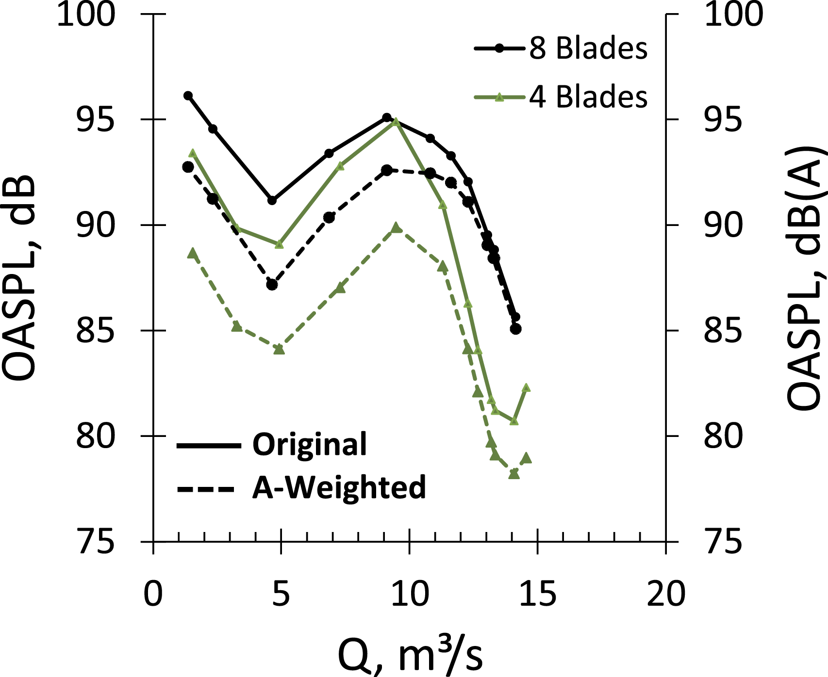
Throttling the system results in continuous increase of the blade inflow angles. Even though a static pressure rise is encountered, entering this instability region is accompanied by local stall phenomena, causing an initial increase of the aeroacoustic signature followed by a temporary decrease due to a broadband reduction in the spectral range of 20 Hz–2 kHz. This stall effect is caused by the fan operation on a secondary characteristic curve in that throttled region. Further reduction of the flow rate extends the stall regime, transiting from local to global, hence significantly affecting the aerodynamic efficiency and resulting in a strong increase of low frequency noise radiation due to the separation of aerodynamic structures of high wavelength. This is also the region where the impact of A-weighting becomes most prominent since spectral components at f < 1 kHz are increasingly attenuated.
Comparing the aeroacoustic signature of the eight bladed versus the four bladed rotor case shows a similar dependency of the aeroacoustic characteristic on the operation point. However, the four bladed impeller shows a clear reduction in total noise which is especially prominent at overload and severe part-load condition. Applying A-weighting of the signature, the aeroacoustic benefits of the 4-bladed impeller are further increased and extended towards the design conditions. Consequently, the underlying mechanisms of the noise reduction are considered to be a shift in spectral range associated with a broadband noise reduction as will be further examined in the subsequent sections.
Incorporating the aerodynamic performance of the tested impeller allows a combined assessment of the aeroacoustic suitability (Figure 11, Eq. (4)) of specific configurations without the need to analyze the aerodynamic characteristics in parallel. The results obtained highlight the benefits at design conditions as well as at off-design. Maximum performance at minimum noise is obtained at Q = 13.3 m³/s, ηTS = 53.2%, ΔpTS = 98 Pa for the 4-Bladed configuration. Overall performance including aerodynamic characteristics acc. To madison et al.
29
oasplm of 8-bladed vs. 4-bladed m-fan.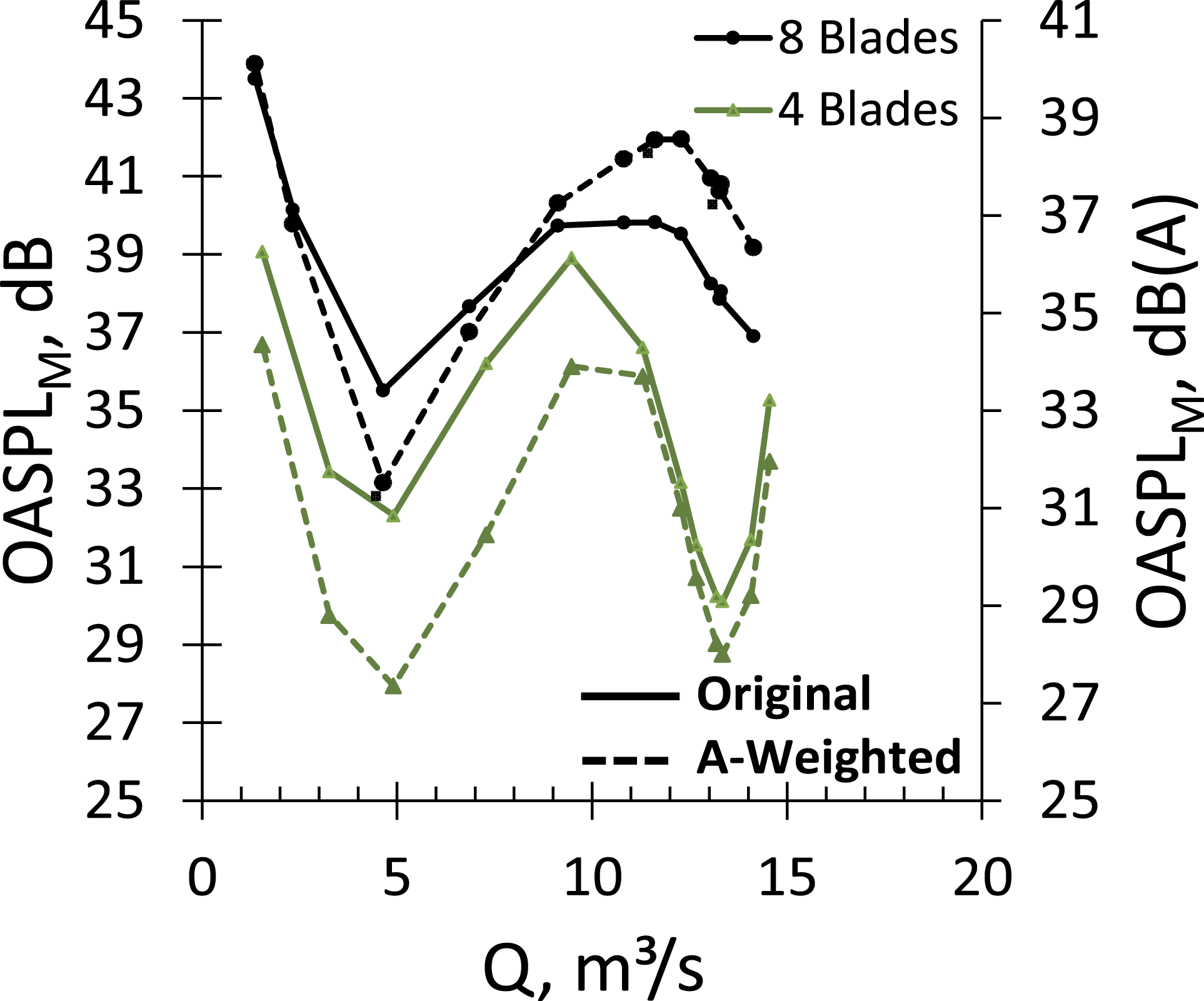
Spectral analysis
The resulting single-number values in terms of the OASPL (Eq. (3)) provide an estimate of the acoustic effects but is unable to give conclusive evidence on the underlying aerodynamic and acoustic root causes and phenomena resulting in the change of the signature. Accordingly, Figure 12 provides the spectral differences of the eight bladed versus the four bladed fan configuration for selected operating conditions. The main noise reduction of the 4-bladed configuration occurs in a frequency band 200Hz ≤ f ≤ 6 kHz, coincidently being also the range of maximum human sensitivity as represented by e.g. A-weighting.
14
For both the magnitude and the associated frequency of the maximum noise reduction, the spectral composition shows to scale with the flow rate or the free stream velocity, respectively. Though at lower magnitude a similar pattern is also seen at high frequencies, where the maximum reduction frequency coincides with the fourth harmonic of the main noise reduction. However, at severe part-load conditions, Q <5 m³/s, high frequency noise increase is encountered for the 4-bladed fan, where the blade self-noise increases at a higher gradient compared to the eight bladed, although showing negligible impact on the resulting overall levels. Spectral noise reduction four bladed vs. Eight bladed configurations at varying operating points at δz = 4 mm, 720 r/min.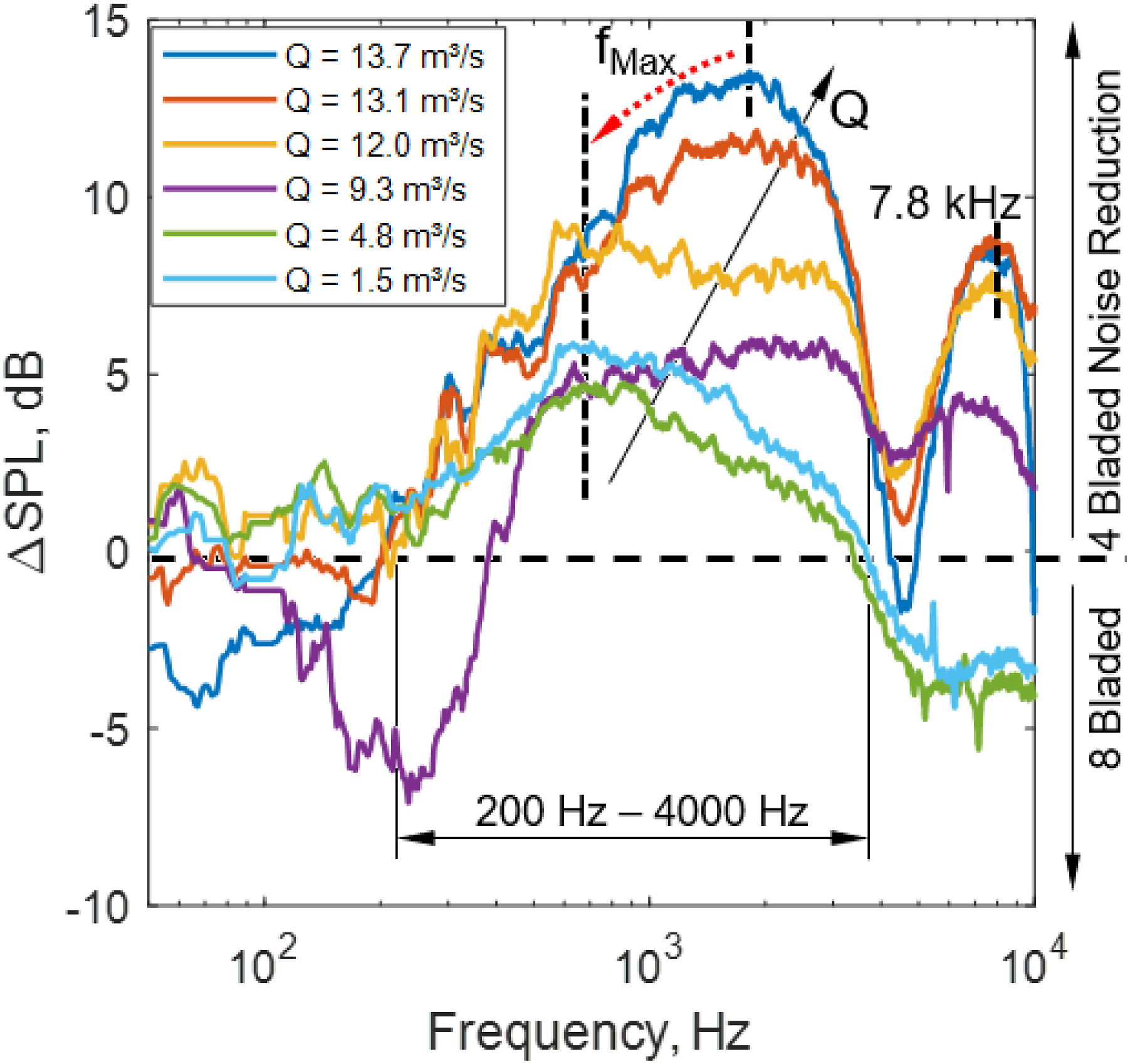
The full picture of the spectral broadband differences is provided in Figure 13 by extending Figure 10 for the full characteristic curves of the eight bladed and four bladed fan configurations. In summary, a significant noise reduction is observed for a wide frequency range resulting in significantly lower overall levels for the four bladed configuration relative to the eight bladed case. Highest aeroacoustic efficiency is obtained at maximum flow rates close to design conditions. Spectral noise reduction four bladed vs. Eight bladed configuration along full characteristic curve at δz = 4 mm, 720 r/min.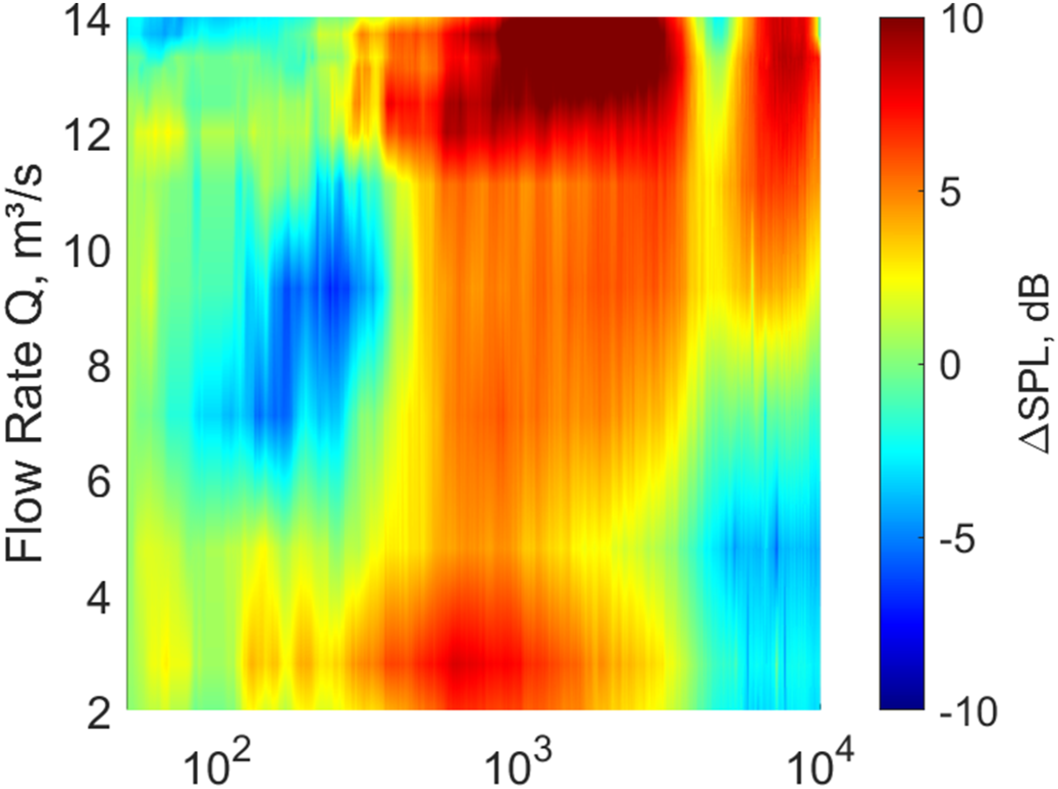
As outlined in Signal processing the local magnitudes of the blade passing frequencies (BPF, Eq. (5)) and their harmonics are analysed for both fan configurations. In general, the first BPF at fBPF = 48 Hz for the four bladed configuration is of significant magnitude (Figure 14) along the entire characteristic curve. On the contrary, the first blade passing frequency of the eight bladed configuration occurs at fBPF = 96 Hz, being of comparable magnitude to the first harmonic of the four bladed case at the same frequency. Comparing development of the BPF-harmonics for the two fan blade configurations shows a comparable magnitude for design conditions whereas approaching part-load conditions, the four bladed harmonics are once again excited to a stronger degree. In opposition to the comparably high initial BPF, being of low impact due to the A-weighting at fBPF,4B(1) = 48 Hz, these higher harmonics increasingly affect the total level of the four bladed fan configurations, resulting in slightly decreased but still existent benefits in direct comparison to the eight bladed configuration. Effect of blade variation on the bpf radiation at design (top) and part-load conditions (bottom), δz = 4 mm, 720 r/min.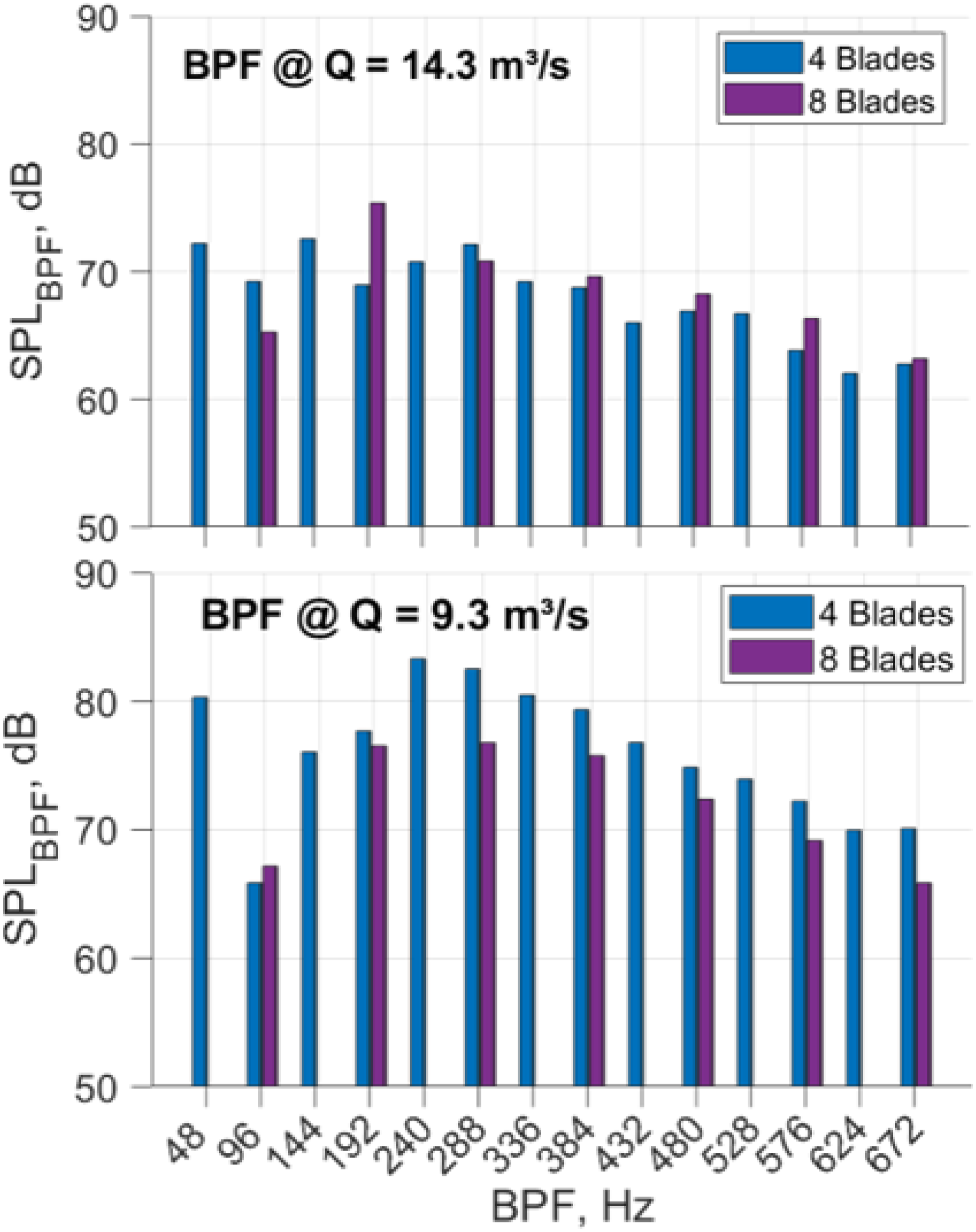
Results and discussion
As outlined in Fan noise sources, the tip clearance is considered one key parameter affecting the aerodynamic performance of axial fans, especially when the chosen vortex design results in an increased loading towards high blade radii. Moreover, the tip clearance is also known for contributing to the resulting aeroacoustic signature in the mid-frequency range in terms of tonal (discrete) and broadband effects. 17 For the current study both fan configurations under investigations are tested at varying tip clearances. The baseline reference case is defined by the radius-normalized maximum tip clearance of 0.26% or 4 mm, respectively. Successive tests at identical aerodynamic conditions were conducted at a tip clearance of 2 mm (0.13%) and 0 mm (0%) while monitoring the aerodynamic and aeroacoustic characteristics. Aerodynamic performance results are discussed first and thereafter the aeroacoustic performance results.
Aerodynamic performance
In Figure 15 below, the effect of the closing tip gap can be seen on the performance of the fans. This is however consistent with literature as tip leakage vortices are reduced and more work performed at the tip.18,21,31,32 Fan performance characteristic curve with tip gap reduction.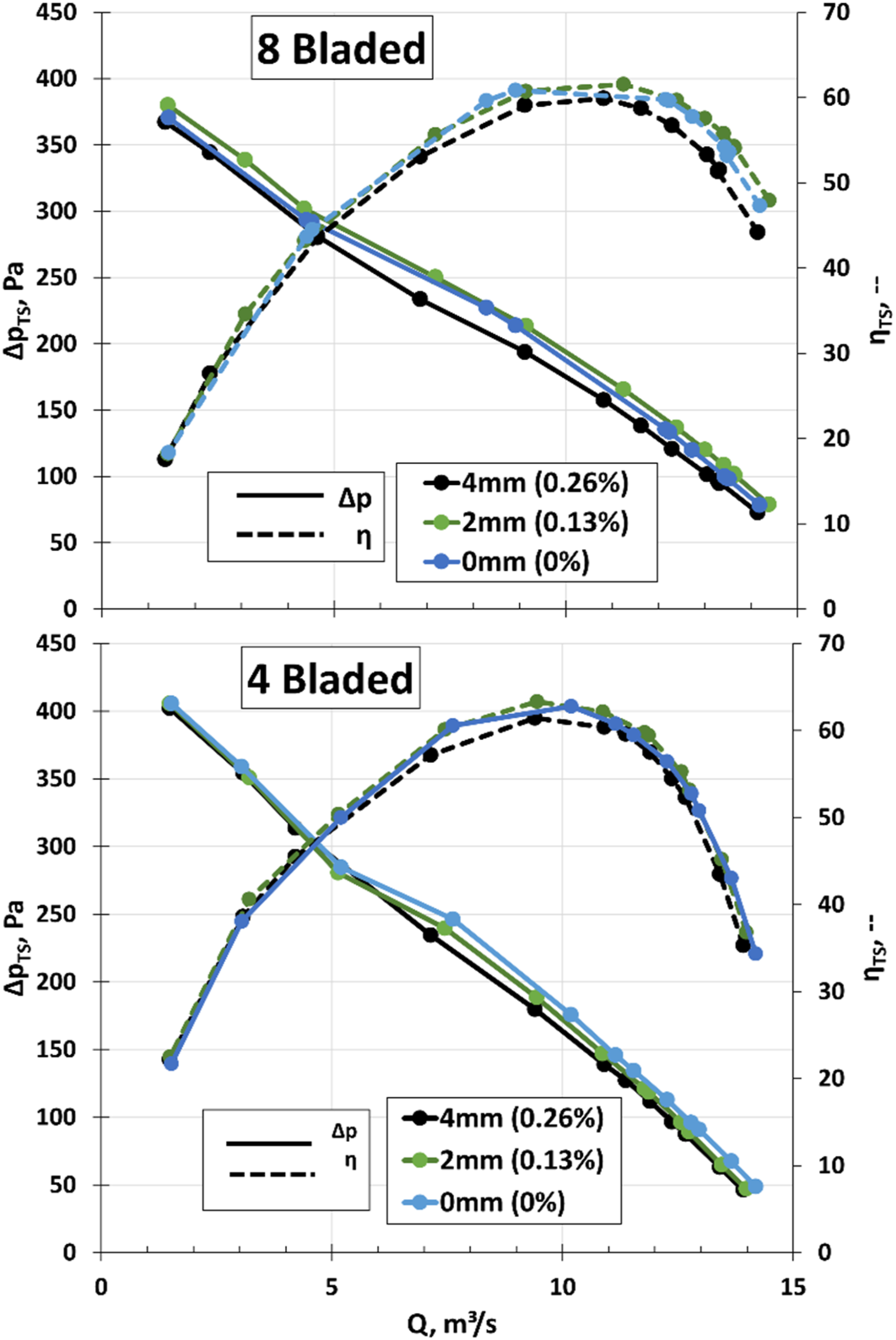
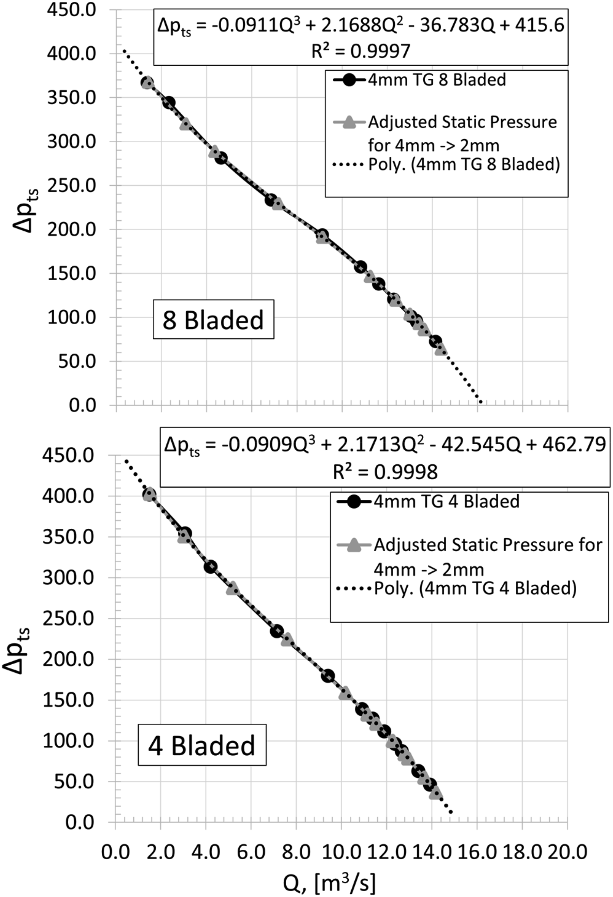
The difference in static pressure rise due to the tip gap reduction is normalized against the maximum pressure of the 4 mm (0.26%) tip gap fan configurations. This is to attain a better view on the increase in performance due to the closing of the tip gap.
To accomplish this, the static pressure distribution for both 4 mm tip gap fan configurations, are shifted along a curve fit to obtain the static pressure of the 4 mm fan configuration at the same flow rates as the 2 mm and 0 mm fan configurations. This allows comparison of the change in static pressure at the same flow rate for the varying tip gaps. The shifting of the static pressure for the 4 mm tip gap fan configurations, including the curve fit equations, can be seen in Figure 16 below. A third degree polynomial curve was chosen as it represented the static pressure curves the best near the design flow rate of the M-fan. The difference ( 4 mm tip gap fan total-static pressure shifted to fit 2 mm and 0 mm tg flow rates to acquire direct comparison.
The increase in performance due to closing the tip gap can be clearly seen for both four- and eight bladed M-fan configurations in Figure 17. The four bladed fan shows a clear performance increase from 4 mm to 2 mm, to 0 mm tip gap, while the eight bladed shows a clear performance increase from 4 mm to 2 mm and from 4 mm to 0 mm, but not from 2 mm to 0 mm. Nevertheless, the results remain clear, that reducing the tip gap leads to an increase in aerodynamic performance of a fan. Normalised static pressure percentage increase relative to 4 mm (0.26%) tip gap case.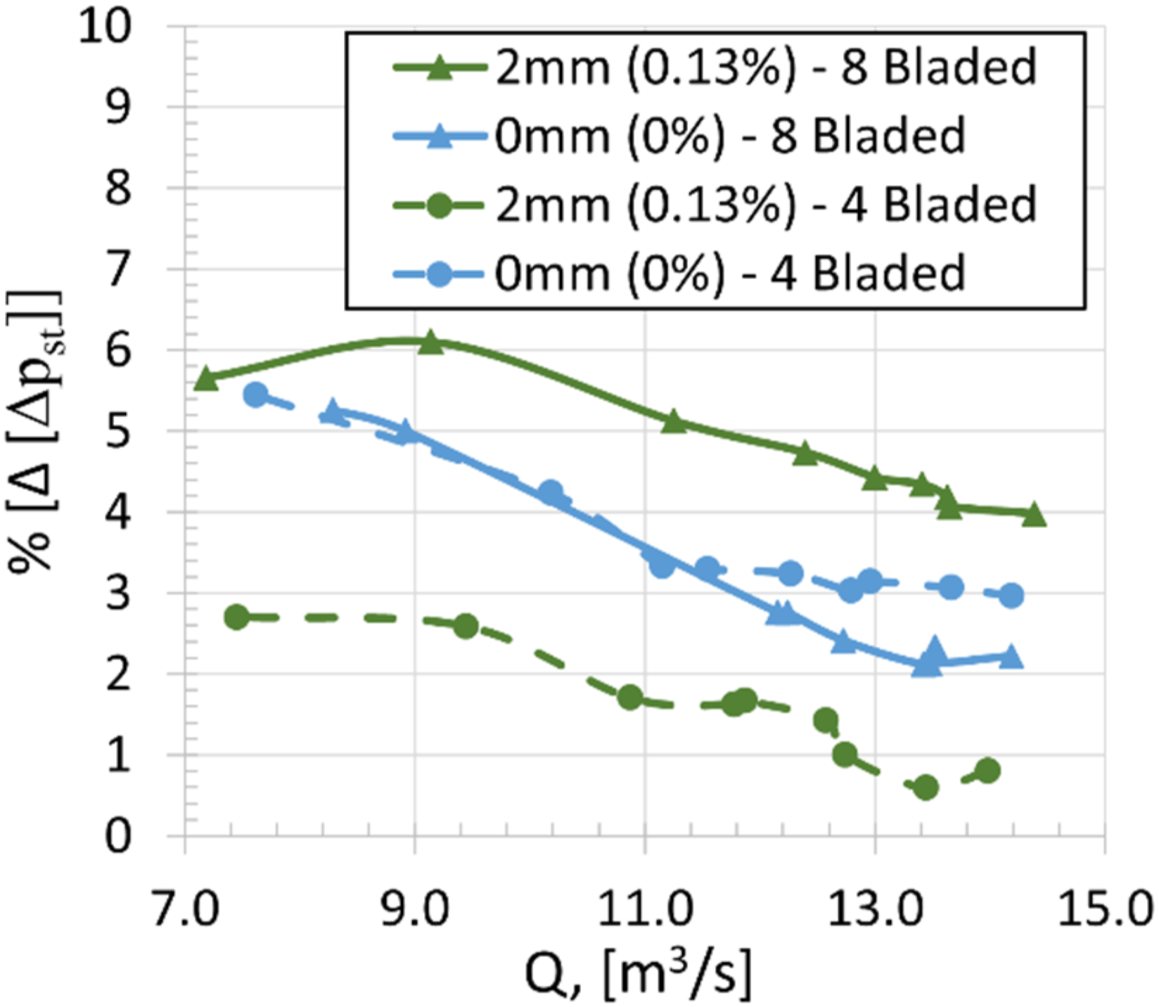
Aeroacoustic performance
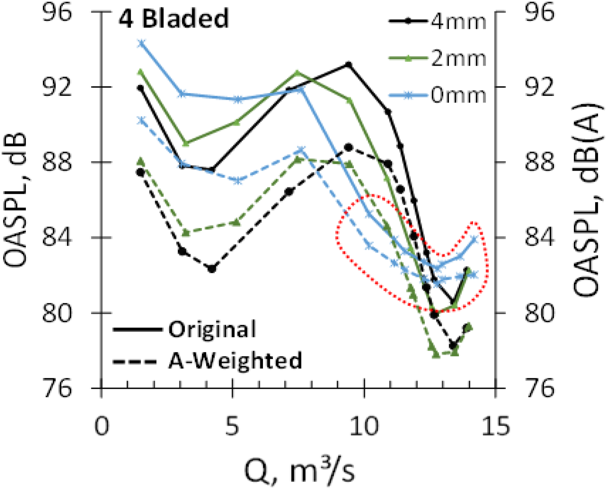
Supplementary to the aerodynamic characteristics in Figures 15–17, Figures 18 and 19 serve to provide information on the general aeroacoustic performance. As can be seen for the original as well as the A-weighted OASPL, minimum tip clearance shows a significant noise reduction for high flow rates Q >10 m³/s, indicating design and overload conditions. This pattern reverses when entering the instability region at Q <10 m³/s, where local stall starts to affect the general fan performance. The underlying effect is considered to be of aerodynamic origin, where at high flow rates smooth flow conditions with low blade incidence angles are present, also resulting in a low to intermediate rise of the static pressure at maximum efficiency. Here, the moderate secondary reverse flows in the blade tip gap region are efficiently reduced by the change in tip clearance. However, reducing the flow rates is accompanied by a rise in the static pressure difference while the blades experience flow separation effects with vortical structures of increasing length scales, resulting in a shift of the noise radiation towards lower frequencies. Here, the capability of the low tip clearance in reducing the reverse flow reduces significantly, where the high-pressure fluid passes the blade tip gap with increased force, increasing the rotating instabilities and interacting with the blade tip of the adjacent blade.16,17 Changing the focus towards the four bladed case in Figure 19, the strong qualitative similarity of the observed trends already indicates a certain ability to generalise the obtained patterns. However, at maximum flow rates Q >10 m³/s an increase in the overall noise is observed particularly at 0 mm tip clearance. The effect can clearly be assigned to rubbing noise between the attached tip flaps and the fan shroud itself, which is aeroacoustically being masked at high noise level (Q <10 m³/s) but getting more prominent and acoustically visible at maximum flow rates. Nevertheless, since this detriment is solely due to current manufacturing restrictions, the noise reduction potential of this application in general is not considered to be affected. Eight bladed m-fan: aeroacoustic performance at varying tip clearance, 720 r/min, δz = 4 mm/2 mm/0 mm. Four bladed m-fan: aeroacoustic performance at varying tip clearance, 720 r/min, δz = 4 mm/2 mm/0 mm.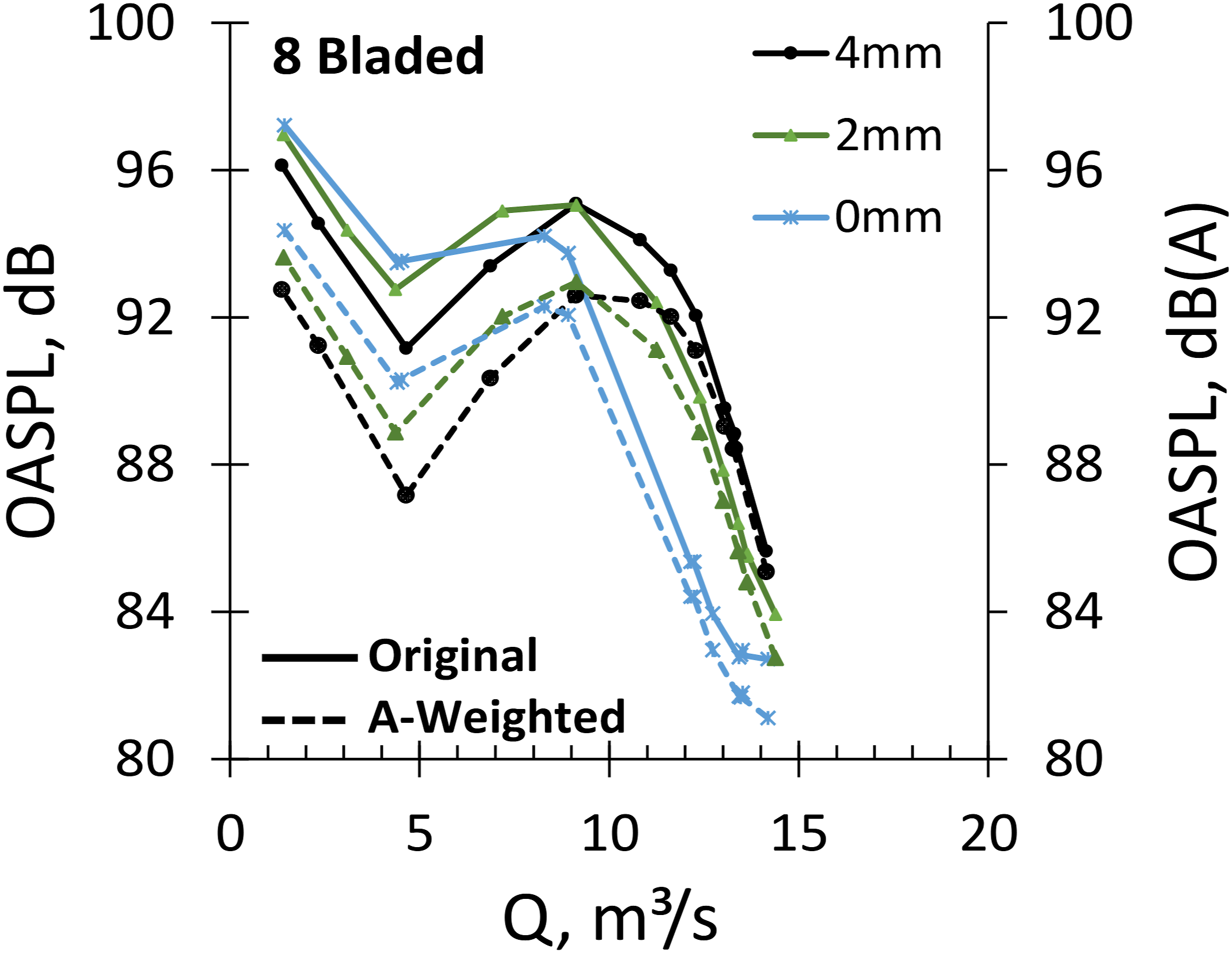
Normalizing the acoustic radiation by incorporating the aerodynamic performance as shown in Figure 20 reinforces the benefits of a small tip clearance at overload and design conditions. Due to the improved aerodynamic characteristics at low tip clearance this range is even extended towards the instability region with Q ≥ 7 m³/s for both the 4-bladed and 8-bladed conditions. The reverse pattern remains existent only at severe part-load Q < 7 m³/s. 4 vs 8 bladed: combined aeroacoustic performance acc. To madison
29
at varying tip clearance, 720 r/min, δz = 4 mm/2 mm/0 mm.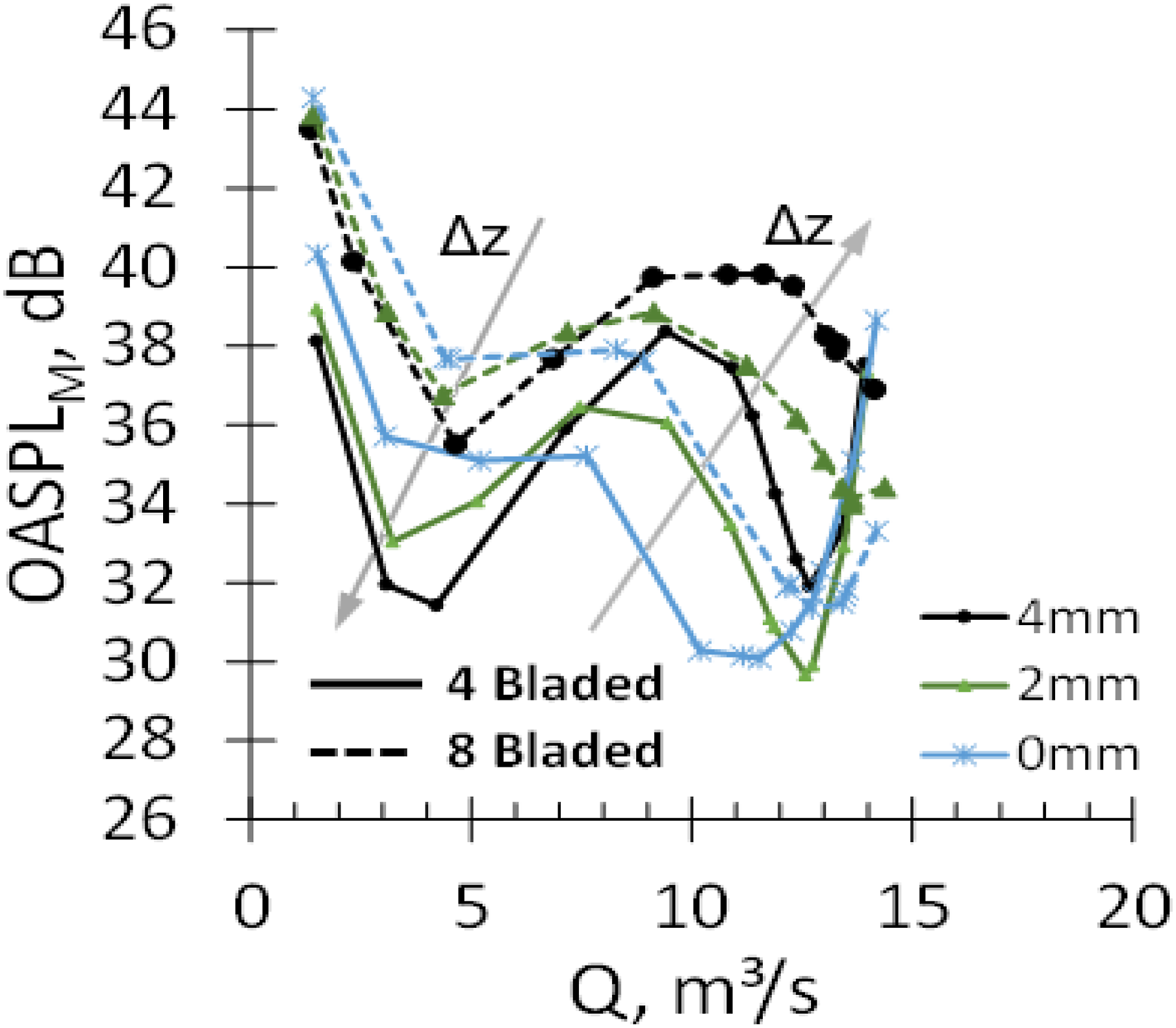
Filtering the gathered aeroacoustic signatures for their respective blade passing frequencies in a narrow spectral range of fBPF± 5 ‘Hz enables to separate the tonal fan speed dependent effects from those of broadband character. Summing-up these discrete components along the frequency, results in single number values as represented in Figure 21 for a frequency band 10Hz ≤ f ≤ 1 kHz, hence covering the level-relevant range of up to 20 BPF harmonics (4-bladed). As can be seen for the four bladed design, a clear scaling from high to low tip clearance manifests over a wide operation range along overload and design conditions, minimum tip clearances perform best. For the eight bladed case, mostly similar BPF-levels at high to intermediate flow rates are observed whereas at flow rates Q <11m³/s, high tip clearance proves to be more beneficial, also being more pronounced at part-load. This can partly be assigned to a changed sensitivity due to the spectral shift since the four bladed design shows to have more pronounced BPFs at lower frequencies. However, the reverse pattern of the tip clearance effect along the characteristic curve generally agrees with the observed overall levels shown in Figures 18 and 19, indicating effects of the tip clearance on both tonal and broadband components. On the other hand, in relative comparison to the total levels, the reversal shows to occur premature for the OASPLBPF, being already present when underrunning flow rates of Q <11 m³/s (8 bladed, Figure 21). 4 vs 8 bladed: sum level based on bpf oasplbpf at varying tip clearance, 720 r/min, δz = 4 mm/2 mm/0 mm.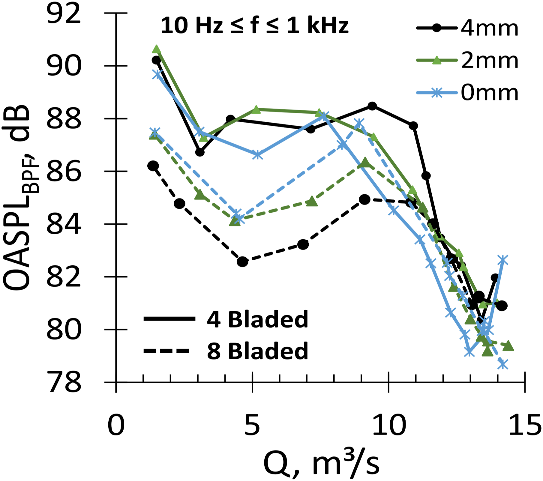
Spectral tip clearance effects
Evaluation of the spectral composition of the aeroacoustic signature enables to conclude on the underlying mechanisms as well as to define the affected spectral range. Figure 22 exemplarily shows the noise radiation close to design condition at varying tip clearance for the eight bladed and the four bladed fan configuration. Especially for the eight bladed case a clear spectral scaling becomes apparent in a frequency band 150Hz ≤ f ≤ 4.5 kHz, also representing the most sensitive region for the human perception of noise, once again highlighting the noise reduction potential of this passive application. The radiated peak noise is reduced by ΔSPL = 6.0 dB from SPL4mm,Max = 60.4 dB towards SPL0mm,Max = 54.4 dB while experiencing a slight decrease in the associated frequency from f4mm,Max = 920 Hz to f2mm,Max = 746 Hz, further reinforcing the noise reduction through A-weighting. For high frequencies, aerofoil self-noise increases in relevance, while tip-clearance effects cease since their underlying effects mainly relate to vortical structures of high to intermediate length scales. These trends are qualitatively confirmed by the four bladed case whereas the total differences are less pronounced. This is considered to be due to a) the lower overall level of the four bladed case and b) the increase (doubling) of the fan blade chord, resulting in a spectral shift of the noise reduction regime towards lower frequencies. Small changes in the spectral pattern can for example also be derived from the small humps of narrowband character at f = 4.4 kHz, indicating laminar shedding noise for the four bladed configuration.
33
Moreover, both the 8-bladed as well as the four bladed configuration show the detrimental impact of the rubbing noise between the attached tip flaps and the fan shroud as already discussed in Aeroacoustic performance, not being of aerodynamic/aeroacoustic origin but preventing assessment of the Δz = 0 mm tip clearance characteristic at high frequencies. Spectral tip clearance effects at 4 mm, 2 mm and 0 mm at high flow rates, eight bladed (left), four bladed (right), 720 r/min.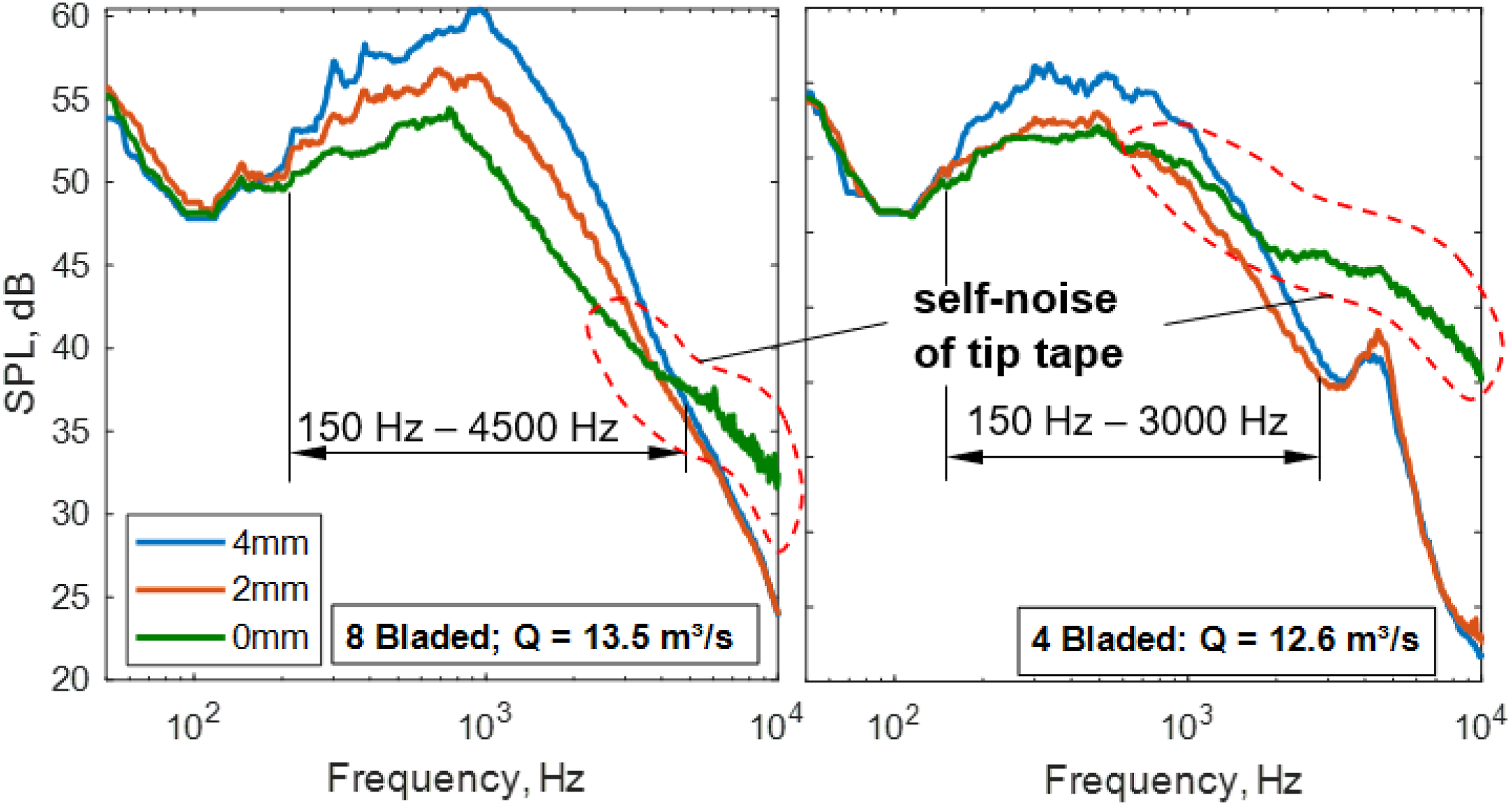
The full picture of the noise reduction potential of varying tip clearance can be derived from Figure 23 (8 bladed) and Figure 24 (4 bladed). Note that the Δz = 4 mm tip clearance case serves as the reference, hence being the one used for relative assessment of the Δz = 2 mm and Δz = 0 mm effects shown. For the eight bladed configuration in Figure 23 a clear dependency of the noise reduction on the respective flow rate is observed. This affects both the spectral extend of the noise reduction as well as the magnitude. Especially at high flow rates a broadband noise reduction 130Hz ≤ f ≤ 5 kHz is present with local differences of up to ΔSPL2mm ≤ 6.3 dB and ΔSPL0mm ≤ 13.0 dB for the Δz = 0 mm configuration. Reducing the flow rate or entering the instability region, respectively, primarily affects the upper spectral threshold which reduces from fupper ≤ 5 kHz (Q = 14.2 m³/s) towards fupper≤ 290 Hz (Q <8 m³/s). At part-load, however, the effect of the tip clearance caves towards blocking large-scale coherent structures of low frequencies, hence also showing a minimum effective frequency range 50Hz ≤ f ≤ 290 Hz. Comparing the two cases of different tip clearance shows a highly similar spectral operation range, supporting the reliability and generalizability of the observed pattern. Eight bladed: spectral tip clearance effects at 4 mm, 2 mm and 0 mm along full characteristic curve, 720 r/min. Four bladed: spectral tip clearance effects at 4 mm, 2 mm and 0 mm along full characteristic curve, 720 r/min.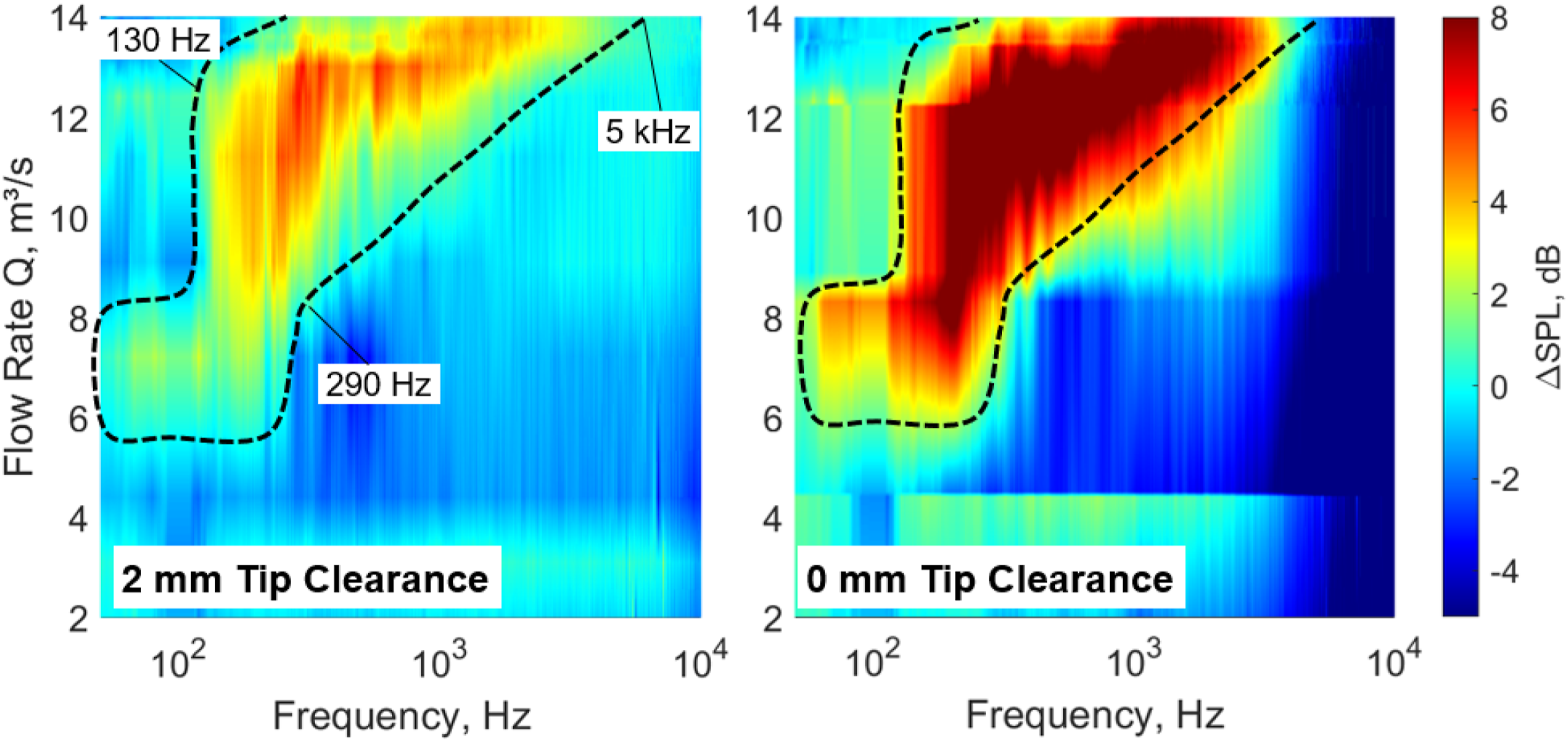
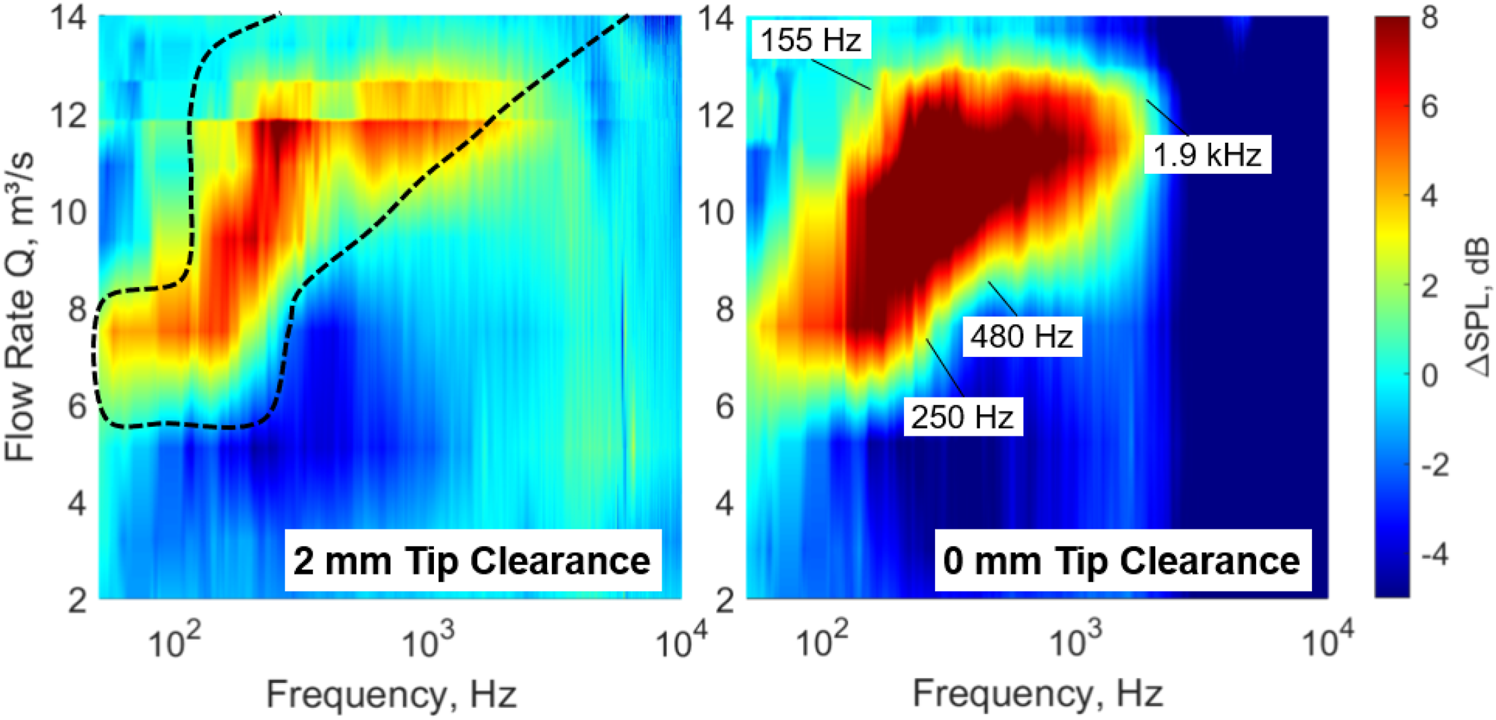
Changing the focus towards the four bladed configuration in Figure 24 does show a comparable pattern on a qualitative level. Nevertheless, the upper spectral range decreases significantly due to the different blade chord and the bisection of the blade passing frequency as can be seen from the dotted regime in Figure 24, transferred from the eight bladed case in Figure 23. In terms of magnitude, the main noise reduction slightly shifts to lower flow rates, being most effective at Q = 11.5 m³/s (8 bladed: Q = 12.7 m³/s). Local differences of up to ΔSPL2mm ≤ 9.3 dB and ΔSPL0mm ≤ 14.6 dB indicate a significant noise reduction potential close to design conditions.
Continuing the BPF analysis discussed in Figure 21 on a local level, Figure 25 shows the distribution of the single BPF and their harmonics for selected operating conditions of the eight bladed fan configuration. At maximum flow rates Q = 14.2 m³/s a clear pattern is observed with the noise at the BPFs being most excited at maximum tip clearance. This pattern is even more prominent close to design conditions at Q = 12.1 m³/s. Here, at moderate total-to-static pressure differences the reverse flow interacts with the blade tip region, where a small clearance is expected to contribute to the spatial uniformity of the blade flow profile, hence resulting in a reduction of the periodic pressure pulses. Moving towards instability and part-load leads to the reversed (8 bladed) or stagnated (4 bladed) effect of the blade tip clearance, already observed for the overall levels depicted in Figure 21. As Figure 25 (bottom, right) indicates, especially at low flow rates, the first BPFs are excited at increased level, almost independent of the tip clearance itself. The harmonics, however, tendentially show slightly higher values for low tip clearances, which is potentially due to the high-pressure gradient at low flow rates in the tip region, forcing the reverse flow fluid through a tip gap of decreased dimension and perturbating the blade tip flow field at increased force. Eight bladed: effect of tip clearance on the bpf radiation alon the characteristic curve from design (top left) to part-load (bottom right), 720 r/min.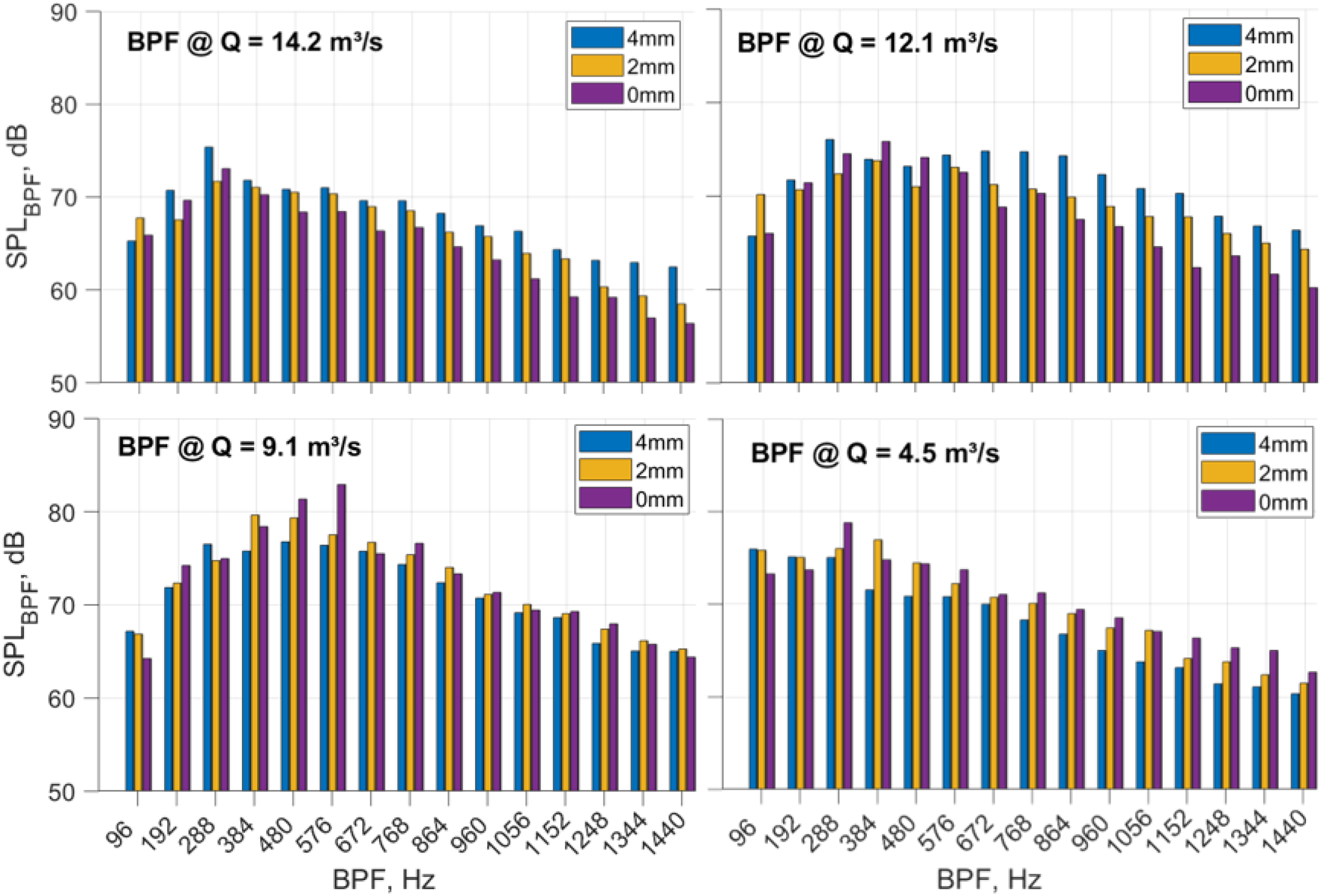
Conclusion
An experimental study of two model fan rotors were conducted. From the results it can be concluded that reducing the number of fan blades from eight to four significantly affects the aeroacoustic characteristic by lowering the broadband noise radiation of the investigated fan. At lower flow rates, A-weighting works in favor of the four bladed fan configuration although it has a higher noise excitation at its BPF than that of the eight bladed. Reducing the tip gap leads to slight improvement of the aerodynamic characteristics but is accompanied by significant reduction of the radiated noise. This is in agreement with the findings of du Plessis 16 and Higgens et al. 34 as the shedding location of tip leakage vortices are shifted towards the leading edge, thus diminishing the size of the vortical structures that will interact with the adjacent blade. Lowering the blade number at constant solidity ratio affects the spectral range by shifting it towards lower frequencies. The superimposing effect of reducing blade number and tip clearance variation was less distinguishable. The practical approach to alter the blade tip gap is considered to represent a starting point for designing a robust yet efficient passive application to be used for fan noise reduction in the industrial environment.
Footnotes
Declaration of conflicting interests
The author(s) declared no potential conflicts of interest with respect to the research, authorship, and/or publication of this article.
Funding
The author(s) received no financial support for the research, authorship, and/or publication of this article.