
Abstract
This study focuses upon a new permeable topology design concept as an alternative to porous metal foams, for turbulent boundary layer trailing-edge (TBL-TE) noise attenuation. The present permeable topology has unconventional characteristics with respect to the metal foams: a combination of low flow resistivity r and high form drag coefficient C. The unconventional characteristics are realized by a Kevlar-covered 3D-printed perforated structure. An experimental study featuring a NACA 0018 airfoil model with a Kevlar-covered 3D-printed TE insert at chord-based Reynolds numbers up to
Keywords
Introduction
Airfoil self-noise, in the form of turbulent boundary layer trailing-edge (TBL-TE) noise, 1 is the major contributor to aerodynamic noise from wind turbines. Excessive exposure to wind turbine noise are found to cause health consequences.2,3 Due to this potential societal impact, in 2018, the World Health Organization has issued guidelines for wind turbine noise, 4 recommending the day-evening-night-weighted Sound Pressure Level (SPL) to be below 45 dB. Subsequent regulations are limiting installation and operation of wind turbines close to densely populated areas. 5 Nevertheless, wind turbine manufacturers today are capable of developing wind turbine blades with spans as large as 100 m, and with tip speeds exceeding 300 km/h. 6 From the dimensional analysis by Curle 7 and Ffowcs Williams and Hall, 8 the acoustic power of the noise produced by the trailing edge of wind turbine blades scales with the fifth- to sixth-power of the relative free-stream flow speed, depending on the compactness of the airfoil with respect to the acoustic wavelengths. With wind turbines growing in size, the problem of TBL-TE noise becomes even more relevant.
Research on passive noise control strategies for TBL-TE noise has been carried out in the last decades by both industry and academic institutions.9–12 One of the most successful methods for attenuating the TBL-TE noise is integration of porous materials into the airfoil shape.13–20 In research conducted by Geyer et al., 14 it was shown that the application of porous materials over the full extent of an SD7003 airfoil could achieve up to 8 dB noise reduction for frequencies below 8 kHz when compared to the solid airfoil.
According to a recent investigation by Rubio Carpio et al., 21 the TBL-TE noise attenuation by such materials is obtained due to partial balancing of surface pressure fluctuations enabled by the permeability between the suction and the pressure sides. Such a mechanism was confirmed by the correlation of the near-surface velocity fluctuations between both sides across the porous metal-foam materials, measured with particle image velocimetry. This pressure-balancing mechanism weakens unsteady pressure imbalances, hence noise scattering, at the trailing edge.
Flow communication across the porous materials also causes balancing of the steady pressure difference between the suction and the pressure sides, leading to a loss of lift. 22 For instance, up to 75% reduction of lift has been reported for highly permeable fully porous airfoils tested in a range of angles of attack between 12 and 24 degrees by Geyer et al. 13 Studies from literature have, therefore, proposed to apply the permeable porous material only at the location where the TBL-TE noise is generated, i.e. as close as possible to the trailing edge. This approach gives a better compromise between the noise reduction and the preservation of the original aerodynamic performance, compared to the fully porous airfoil.16,19,20,23
To date, many studies have identified links between characteristics of the porous materials to aeroacoustic characteristics of airfoils equipped with them.13,15,18 The permeable materials are usually characterized by their resistivity (inversely proportional to the permeability) and form drag coefficient.24–27 Since the form drag coefficient usually increases gradually with the increasing resistivity,20,28 only the latter has mostly been sufficient to be related to the aeroacoustic characteristics.13,15 Generally, it has been found that decreasing the resistivity, potentially by increasing the pore size of the porous materials, increases the noise attenuation. For example, an experimental investigation of Herr et al.
18
featuring a DLR F16 airfoil at chord-based Reynolds numbers between 0.8
In addition, complex dependencies of the noise attenuation with the angle of attack provided by porous airfoils have been presented by Sarradj et al. 15 and Geyer et al.. 13 Generally, the ability of fully and partially porous airfoils in TBL-TE noise attenuation seems to deteriorate when the airfoil loading, i.e. angle of attack, increases.18,30 This deterioration appears to be more pronounced as the cell diameter of the porous topology increases. 16 Aerodynamic performances also clearly depend on the resistivity of the porous material. Sarradj et al. 15 showed a clear reduction of lift and an increase of drag of a fully porous SD7003 airfoil with decreasing resistivity. The latter can be attributed to the surface roughness since cellular materials (i.e. open foams, generally metallic), which often entail high surface roughness, have been used in most of the previous research works. Increasing the pore size of such materials increases the surface roughness, and hence the friction drag. 18 Increasing surface roughness also introduces the so-called roughness noise in a range of relatively high sound frequencies.16,18 The frequency above which the TBL-TE noise emission of the (partially) porous airfoil exceeds that of the reference solid airfoil is generally known as the crossover frequency.16,20 For instance, Herr et al., 18 found that the crossover frequency of the TBL-TE noise emission of the partially porous DLR F16 airfoil is around 9 to 12 kHz. The crossover frequency has been found to vary inversely with the pore sizes.15,16,18,20
Despite the promising noise attenuation capability of the porous materials proven by experimental results in literature, usage of such materials with large airfoils or in operating wind turbines could still be unappealing for industrial manufacturers. The permeable materials typically employed in the previous studies consist of randomized pore distribution resulting from the electrodeposition manufacturing processes.15,16,20 Apart from the aforementioned drag and roughness noise increase due to the rough topology, large-scale realization, including manufacturing and maintenance, of such a complex topology could be very challenging.
More recently, simplified perforated topologies comprising of an array of straight channels linking the suction and the pressure sides of the airfoil have also been employed as another alternative to the porous (metal) foam materials.17,28 The investigation by Herr et al. 18 discussed previously also featured a micro-perforated TE insert which could achieve a comparable noise attenuation of approximately 6 dB to more conventional porous topologies such as the porous aluminium. A similar finding has been reported by Rubio Carpio et al. 28 for a NACA 0018 airfoil with 3D-printed TE inserts by which, when the number of straight channels per unit area is increased in order to reach a sufficiently low level of resistivity, a comparable TBL-TE noise attenuation to that achieved by a porous metal-foam insert can be obtained. Nevertheless, care has to be taken when reducing the resistivity of such a perforated structure as tonal noise may appear. Herr et al. 18 and Rubio Carpio et al. 28 have commonly reported tonal noise increase found in their highly permeable variants of the perforated structure. It has been hypothesized that the tonal noise is caused by vortex shedding across regions of regular perforation,18,31 yet this issue has not further been addressed.
The downsides of the permeable materials discussed earlier, namely the surface roughness, the applicability, and the airfoil loading dependency of the metal foams as well as the tonal noise of the perforated channels, may not be overcome by the usage of conventional homogeneous permeable materials. Previous research works have anticipated that ‘tailoring’18,31 the permeable material properties along the chord may mitigate issues such as the tonal noise increase. However, some issues such as the surface roughness may be mitigated only partially. As an alternative, this paper focuses on tailoring the overall permeable material property in the direction normal to the chord. An unconventional combination of the flow resistivity and form drag coefficient is proposed. The concept is realized by combining two permeable materials: a 3D-printed perforated structure covered by a Kevlar fabric. The present study focuses on the use of a highly permeable 3D-printed insert with straight channels to form a simple perforated structure. The pores directly connect regions of the suction and the pressure sides, allowing a point-to-point communication between both sides. On the other hand, a stretched Kevlar fabric, which has widely been used in aeroacoustic applications to replace hard walls of closed-section wind tunnels to allow for acoustic measurements32–36 due to their ability to be acoustically transparent while being aerodynamically impermeable,33,34 is used to cover the surface of the 3D-printed perforated structure. There are two main purposes; first, the relatively smooth texture of the Kevlar fabric is expected to mitigate the roughness noise; second, the flow-impermeable Kevlar fabric is used to cover the regular highly permeable 3D-printed pattern to prevent the tonal noise generation. Overall, this present permeable material combination is expected to provide a mixture of low resistivity (given by the highly permeable 3D-printed pattern) and high form drag coefficient (given by the Kevlar sheet). Aeroacoustic characteristics of an airfoil with Kevlar-covered 3D printed TE insert is investigated with a close comparison to two other metal-foam TE inserts of which well-established characteristics are available in literature.16,20,21
This paper is structured as follows: first, the perforated 3D-printed structure with and without the Kevlar fabric is characterized for their permeability and form drag coefficients to establish a baseline trend with respect to two metal-foam materials. The airfoil model with TE inserts made of those permeable materials is tested in an open-jet anechoic wind tunnel, subjected to a range of free-stream flow speeds and angles of attack. Quantification of the far-field noise and its variation, as well as localization of the dominant scattering noise sources, are achieved by means of microphone array beamforming. In addition, the wake survey method is employed to compare the drag coefficients of the airfoil with the different permeable TE inserts. Finally, based on the analysis of the acoustic and drag results and their links to the material properties, a general design recommendation for the permeable topology for the TBL-TE noise attenuation is given.
Materials, models, and experimental techniques
Wind-tunnel set-up and permeable TE specifications
A NACA 0018 airfoil with interchangable permeable TE inserts was studied in the anechoic vertical wind tunnel (A-Tunnel) at Delft University of Technology (TU Delft).37 The airfoil was mounted on a 400 mm × 700 mm nozzle opening via two parallel side plates. The chord c was 200 mm and the span was two times the chord. The interchangeable TE inserts made up 20% of the chord. A schematic of the set-up is shown in Figure 1.
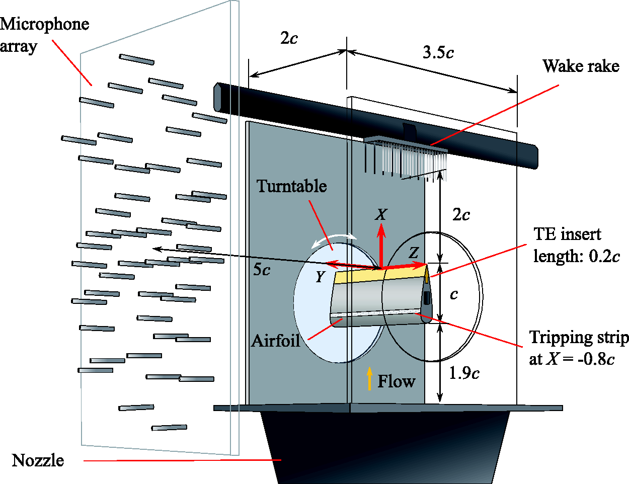
Schematic of the wind-tunnel test set-up, measurement devices, and coordinate system.
The free-stream flow speed
Figure 2 shows the 3D-printed permeable TE insert covered by the Kevlar sheet installed on the NACA 0018 airfoil model together with close-up views of the 3D-printed TE insert and the Kevlar fabric alone. The 3D-printed permeable TE insert was produced using an Ultimaker 3 3D printer. Polylactic Acid (PLA) was used as printing material. The honeycomb-like pattern was obtained by replicating the unit pattern shown in Figure 2. The hexagonal voids were surrounded by 0.8-mm-width 3D-printed PLA edges, forming a perforation parallel to the Y direction connecting the pressure and the suction sides of the airfoil.
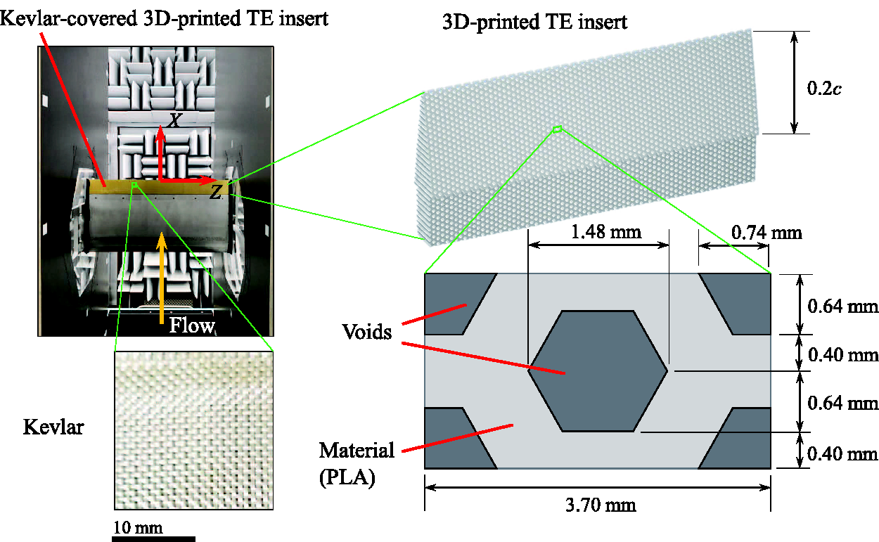
3D-printed permeable TE insert covered by Kevlar installed on a NACA 0018 airfoil model with a close-up view on the Kevlar fabric, the 3D-printed TE insert, and the perforated pattern.
The wind-tunnel tests were carried out both with and without the Kevlar sheet covering the 3D-printed TE insert. For the Kevlar-covered 3D-printed TE insert case as shown in Figure 2, the Kevlar sheet was glued to adhere on the surface of the 3D-printed permeable TE insert. The aviation-standard Kevlar 49 T 965 fabric provided by Engineered Cramer Composites 38 was used. The Kevlar foil has a weight-to-area ratio of 61 ± 3 g/m2, a density of 1.45 ± 0.05 g/m3, and a thickness of 0.12 ± 0.02 mm.
Porous metal-foam TE inserts were also tested on the airfoil as baseline references. The porous metal foam made of NiCrAl was manufactured by Alantum, featuring dodecahedron-shaped cells. Due to the well-established characterization and experimental data in the literature, the porous metal-foam TE with a cell diameter dc of 0.8 mm and 0.45 mm were chosen. Details on these porous metal-foam TE inserts, as well as their extensive test results can be found in previous literature.16,20,21
Permeable material characterization
Characterization of the 3D-printed perforated structure with and without the Kevlar sheet was performed in order to establish a baseline trend for comparison with the porous metal-foam materials. A cylindrical material sample made of the same material having the same perforated pattern as the TE insert was used. The diameter of the cylindrical sample was taken as 55 mm. The thickness t of the material sample was chosen to be 60 mm, according the recommendations from previous tests. 16 Characterization was done by measuring static pressure drop values across the sample. To achieve this, a high-pressure air supply of up to 10 bar was passed through an Aventics pressure regulator and a TSI 4040 volumetric flow meter (range: 0 to 2.5 m/s, accuracy: 2% of reading 20 ) to reach a test section containing the material sample. An exploded view of the test section is shown in Figure 3. The 3D-printed permeable material with the pore direction aligned with the flow direction in the test section was tested with and without a stretched Kevlar sheet covering at the entrance and the exit of the permeability test section. This alignment provides a representation of the material properties across the airfoil in the direction normal to the chord, i.e. between the suction and the pressure sides.
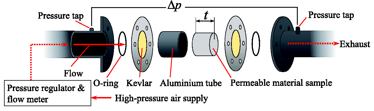
Exploded view of the permeability test section.
The static pressure drop
The characteristics of the material are coefficients of the so-called Forchheimer equation
25
or the Hazen-Dupuit-Darcy equation
27
which is a quadratic equation describing

Microphone array for acoustic measurement
Acoustic signals were recorded using an array of 64 GRAS 40PH microphones (frequency response
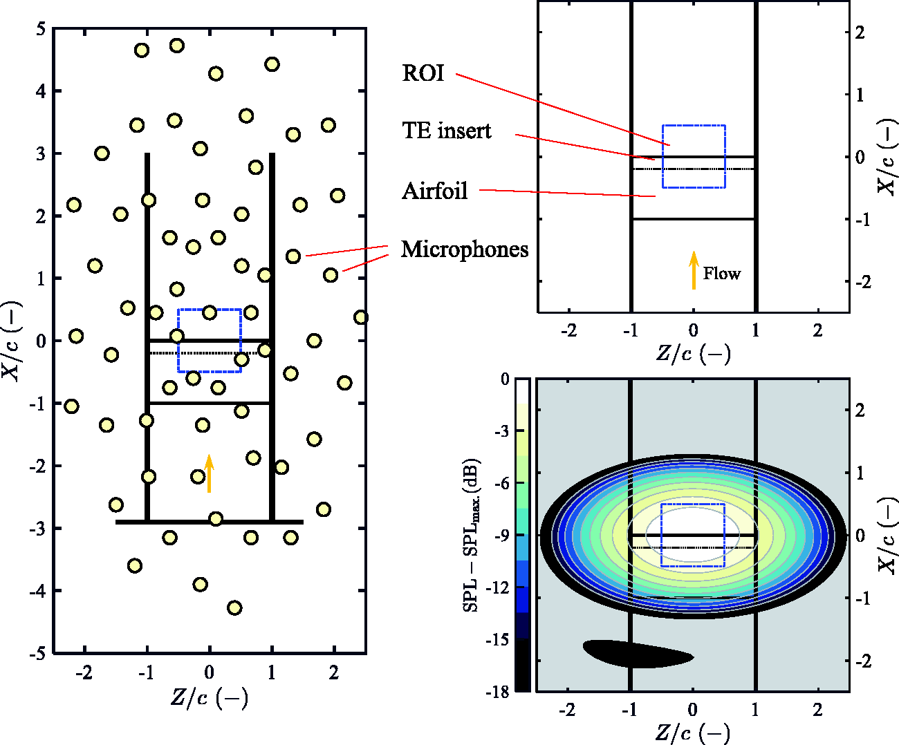
Schematic of the microphone array and the ROI locations relative to the NACA 0018 airfoil model. The source map shows a point spread function at 1 kHz of a point source placed at the origin.
The Rayleigh resolution limit 42 regulates the minimum distance where two sound sources can still be discerned. For the present set-up, the Rayleigh resolution limit for the intended 1/3-octave band frequency range for beamforming is expected to range from 0.44c to 1.75c in the streamwise (X) direction.
Conventional Frequency-Domain Beamforming (CFDBF)
43
was first applied to reveal the acoustic source map. Then, in order to accurately extract only the TBL-TE noise from the source map, the source power integration (SPI) method44–46 was employed where the Region of Integration (ROI) was defined as shown in Figure 4. The ROI covers only half of the span in order to avoid the possible corner sources.44,46 In addition, the SPLs below –6 dB relative to the maximum SPL in the CFDBF source map at each frequency were rejected from the integration to avoid inclusion of side lobes. Having obtained the source power, the SPLs were calculated using the reference distance of 1 m, meaning that the presented SPLs are as observed at
Drag coefficient measurements
A wake survey was performed using a traversing wake rake to measure momentum deficits and thus extract the profile drag coefficients cD of the NACA 0018 airfoil model with different TE inserts.47,48 The wake rake consisted of 50 and 12 total and static pressure probes, respectively. The total pressure probes spanned a distance of
Effective angle of attack determination
Since the tests were conducted in an open-jet wind tunnel, the effective angle of attack
It is assumed that the relationship between

Static surface pressure distribution data, collected by 30 pressure taps having a diameter of 0.4 mm distributed on the airfoil surface, was used to determine
A contour map illustrating the SSEs for different combinations of kB and ϵ is given on the left plot of Figure 5. The lowest SSE was obtained at
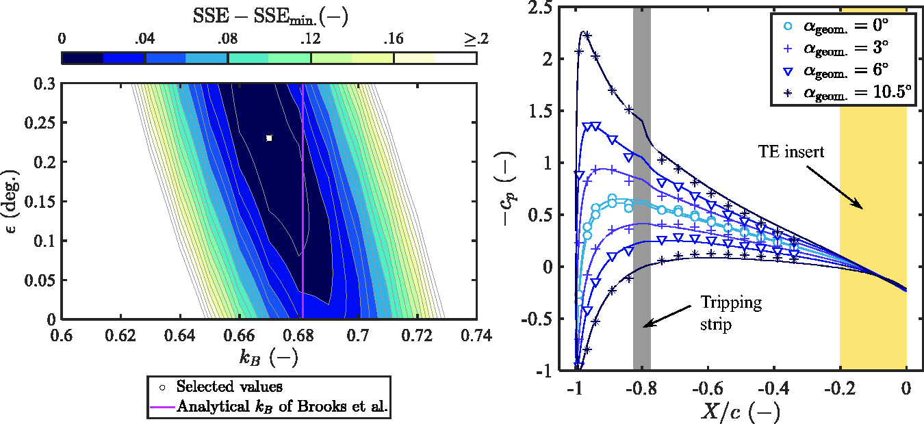
Left: contour plot visualizing the SSEs between the measured pressure distribution and the pressure distribution resolved by XFOIL for different combinations of kB and ϵ. Right: pressure distribution on the NACA 0018 airfoil at Rec = 4.6
On the right plot in Figure 5, the pressure distributions at four different
For the remainder of this paper, data from the four
Results and discussion
Permeable material characteristics
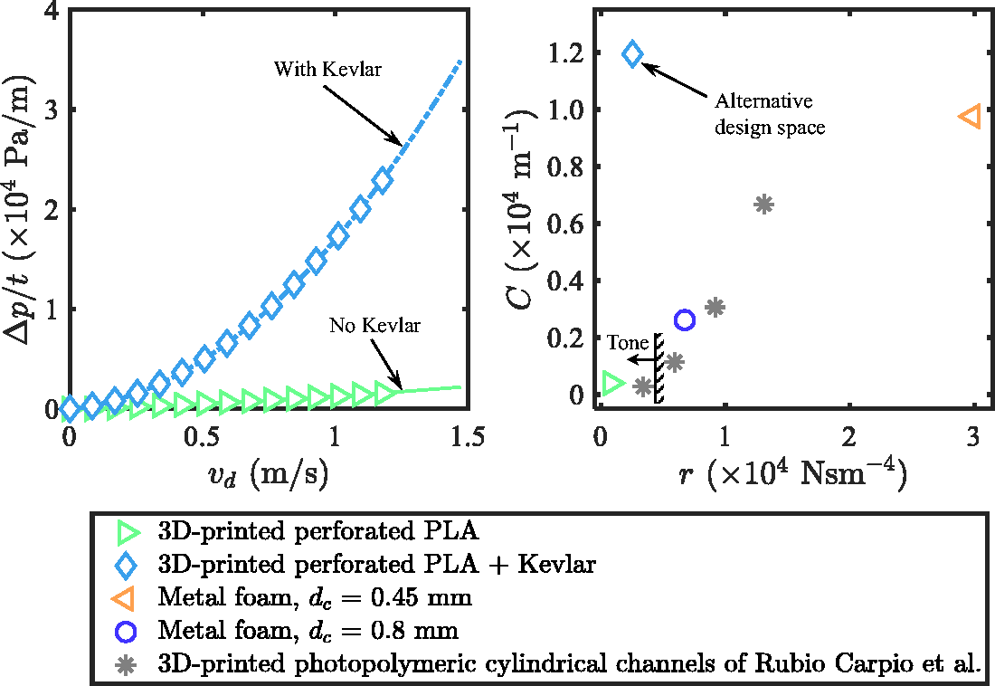
A plot showing the measured static pressure drop
Left: measured static pressure drop
Measured properties of the permeable material samples and metal-foam materials.
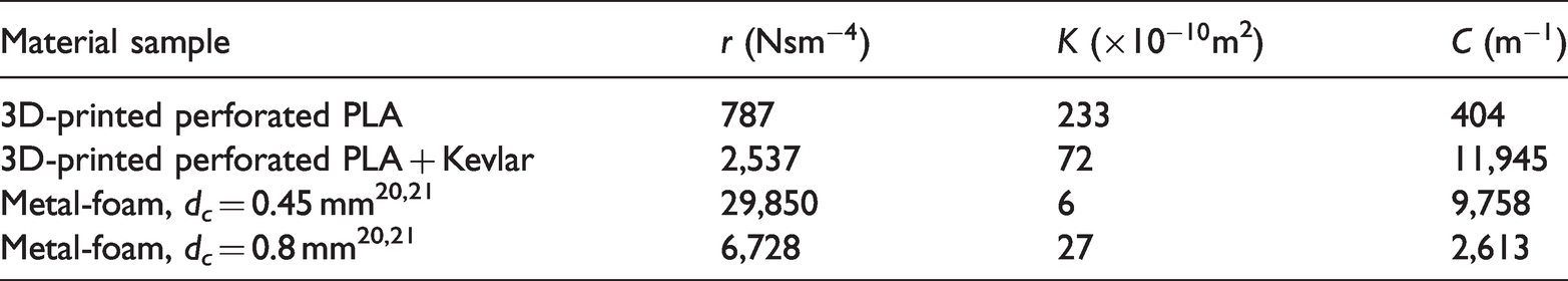
For the perforated 3D-printed PLA sample without the Kevlar sheet, a relatively low static pressure drop is observed, resulting in the lowest r. This is mainly due to the alignment of the straight pores with the flow direction in the permeability test section which facilitates the air flow. On the other hand, the 3D-printed perforated material sample with the Kevlar sheet shows an increase of the static pressure drop as well as a higher sensitivity of the static pressure drop with the increasing vd. This results in an increase of r and a drastic increase of the form drag coefficient C, the coefficient of
A scatter plot visualizing the measured r and C of the permeable material samples tested and those from the metal-foam samples is given in Figure 6 (right). Apart from the present (Kevlar-covered) 3D-printed perforated material and metal-foam samples, the values of r and C of multiple 3D-printed photopolymeric cylindrical channel samples used in the work of Rubio Carpio et al.28,31 are also shown. It is important to note that, for these particular cases, the material sample thickness t is 10 mm instead of 60 mm. Nevertheless, the values of r and C, if the thickness t would be 60 mm, are not likely to differ drastically from the values shown since t is already much larger than the pore sizes and cell diameters. 16 Thus, the relative trends are still worth being compared to the present materials. The readers are referred to the original publication28,31 for detailed specifications of these particular material samples. For the 3D-printed perforated material without the Kevlar sheet as well as the metal-foam materials, the increase of C seems to correlate with the increase of r in a similar fashion. The increase of C with respect to r for the 3D-printed photopolymeric material having cylindrical channels also appears to follow the aforementioned trend in a slightly less gradual manner. Distinctively, the 3D-printed perforated material with the Kevlar sheet is far different from this trend; for a relatively low value of r, the value of C is around the same order of the metal foam sample with dc = 0.45 mm, which has the highest r. This means that the application of the Kevlar sheet on a highly permeable 3D-printed perforated topology creates a rather unconventional combination of r and C.
The present topology of the 3D-printed perforated material sample with and without the Kevlar sheet give lower values of r than the lowest value of r found in the collection of 3D-printed photopolymeric materials. In the literature, 28 tonal noise increase by the airfoil equipped with the 3D-printed TE insert with the lowest r has been reported, suggesting that there exists a threshold of r below which the tonal noise would occur. The location of this threshold lies somewhere between the case with the lowest r and the case next to it, where the tonal noise was no longer found. An approximated location of this threshold is also illustrated in Figure 6 (right). Thus, in the present investigation, one could certainly expect the airfoil equipped with the 3D-printed perforated trailing-edge insert without the Kevlar sheet to also produce the tonal noise. However, for the 3D-printed perforated insert with the Kevlar sheet, despite also having a lower value of r than the identified threshold, production of the tonal noise is less certain. This is because the high value of C which does not follow the aforementioned general trend may play a role. Noise emission characteristics of the airfoil equipped with these materials as permeable trailing-edge inserts are investigated in the coming sections.
Narrow-band noise spectra
The measured narrow-band SPL spectra (frequency resolution of 10 Hz) at
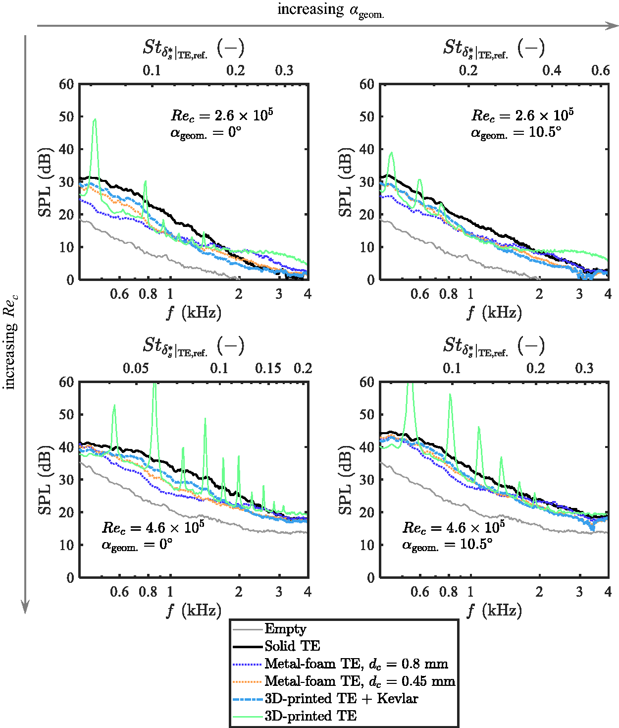
Narrow-band SPL spectra of the NACA 0018 airfoil with various permeable TE inserts at different given combinations of chord-based Reynolds numbers and geometrical angles of attack, compared to the reference solid TE insert and empty test section background noise.
Comparing the spectra with the measured noise from the empty test section, a signal to noise ratio between 5 and 15 dB is obtained up to
For the metal-foam TEs, up to 10 dB broadband attenuation at low frequencies as well as a broadband noise increase at high frequencies are observed. The magnitudes of noise attenuation and noise increase follow the dimension of the cell diameter dc. As explained in previous studies, increasing dc reduces the flow resistivity r (see the previous section) which in turns increases noise attenuation.18,29 However, increasing dc also increases surface roughness which results in the increasing roughness noise at high frequencies.13,15,18,21
For the 3D-printed perforated TE insert without the Kevlar sheet, despite having a broadband noise attenuation compared to the solid counterpart, a series of strong tonal peaks are observed as anticipated. In addition, noise increase due to roughness at high frequencies can also be seen. The magnitude of the roughness noise is higher than that given by the metal-foam TE with the largest dc, thus implying the 3D-printed permeable TE has a higher equivalent roughness than that of the metal foam. This is reasonable since the hexagonal 3D-printed pore has a larger diameter than the largest dc of 0.8 mm of the metal foam. Additionally, the pores extend to the opposite side of the airfoil, creating a much larger effective depth than the pore cells in the metal foams.
When the Kevlar sheet is applied on the 3D-printed perforated insert, the tonal peaks as well as the roughness noise are mitigated. A broadband noise reduction of approximately 5 dB with respect to the solid TE is observed. The spectra of the Kevlar-covered 3D-printed perforated TE insert case seem to be comparable to those of the metal-foam TE insert with dc = 0.45 mm; the Kevlar-covered 3D-printed perforated TE insert gives approximately 2 dB less noise attenuation at low frequencies and 2 dB more roughness noise attenuation at high frequencies. Noticeably, despite having much lower flow resistivity r than the metal-foam material with dc = 0.45 mm, the Kevlar-covered 3D-printed TE does not give additional noise attenuation compared to this metal foam case. This suggests that the ranking according to r may not be a good indicator of the ranking of noise attenuation when permeable materials with different topologies are considered altogether. 28 In the upcoming sections, dependency of noise attenuation magnitude on different material characteristics is further discussed to identify a better indicator for noise attenuation based on the permeable material characteristics.
Interestingly, although the value of r for the Kevlar-covered 3D-printed permeable material is lower than the threshold below which the tonal noise is expected, the material has a high value of C, and, evidently, this characteristic helps to mitigate the tonal noise. Therefore, with a slight modification, it is possible to still maintain a low value of r while preventing the tonal noise. One possible way is by increasing the form drag coefficient C across the permeable topology, e.g. by applying the Kevlar sheet on the surface.
To further address the tonal noise, the spectra from the 3D-printed perforated TE without the Kevlar sheet are exclusively examined. The highly permeable 3D-printed perforated pattern may cause a sudden streamwise impedance jump, creating effectively a blunt trailing edge
1
at the junction between the solid and the permeable part of the airfoil at X/c = −0.2. This could promote tonal noise resulting from vortex shedding.18,31 Figure 8 shows exclusively the measured spectra of the 3D-printed perforated TE insert case, from which the tonal noise is produced, for all the Rec considered at
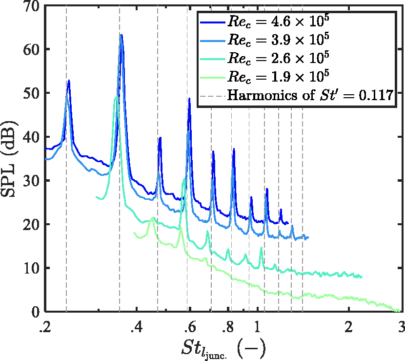
Narrow-band SPL spectra of the NACA 0018 airfoil with the 3D-printed perforated TE insert at different chord-based Reynolds numbers and zero-degree geometrical angle of attack presented in terms of the Strouhal number based on the thickness of the airfoil at X/c = −0.2, together with vertical lines marking harmonics of the fundamental Strouhal number.
Broadband noise attenuation and variability with angle of attack
To further highlight the broadband attenuation of TBL-TE noise, Figure 9 shows the values of
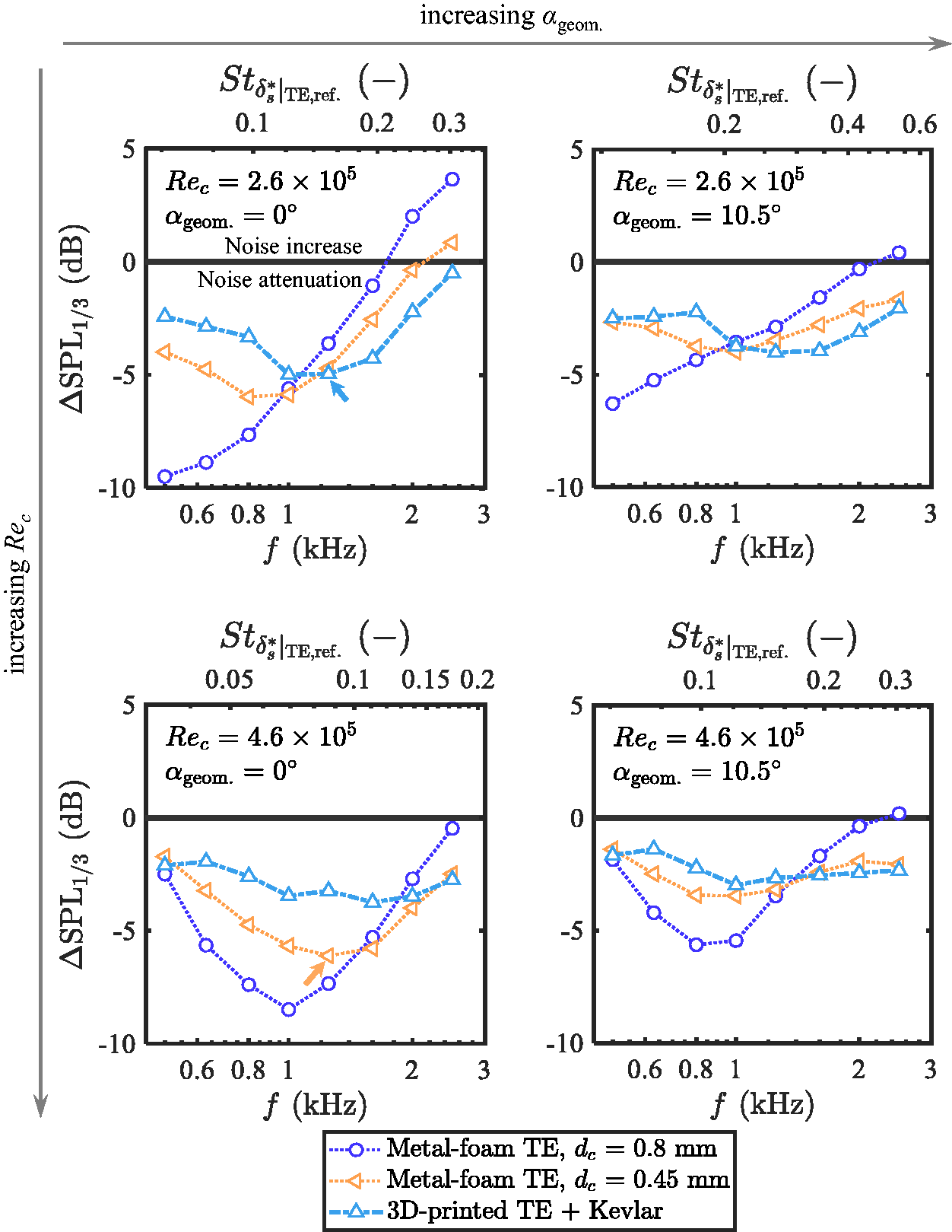
1/3-octave band SPL spectra of various permeable TE inserts at different combinations of chord-based Reynolds numbers and geometrical angles of attack relative to those of the reference solid TE case (
For
When
To address the noise attenuation variability, let 
Thus, by definition, a positive value of
Examination of
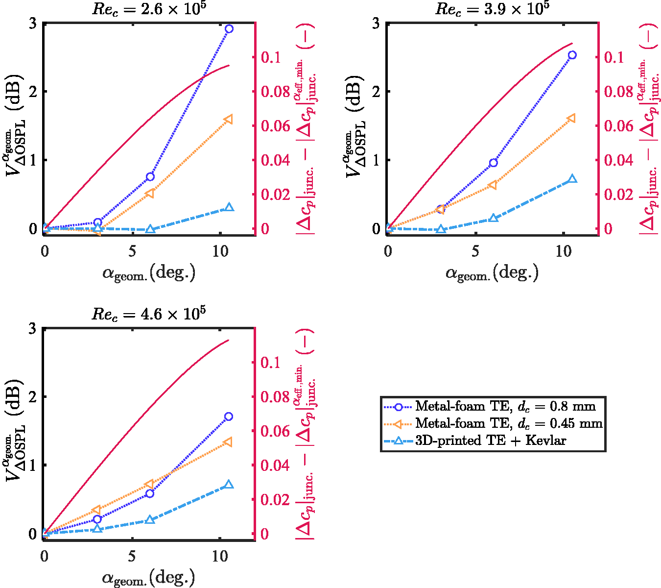
Noise reduction variability with respect to the angle of attack of various permeable TE inserts at different chord-based Reynolds numbers relative to the noise reduction at zero-degree geometrical angle of attack.
Similarly, an increase of
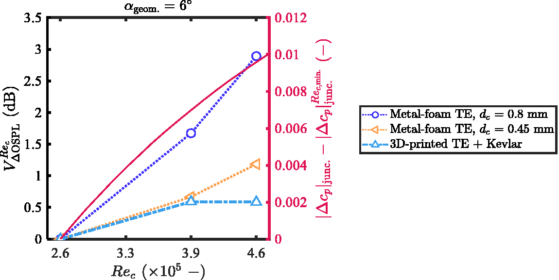
Noise reduction variability with respect to the chord-based Reynolds number of various permeable TE inserts at a geometrical angle of attack of 6 degree relative to the noise reduction at the lowest chord based Reynolds number.
Material properties and noise attenuation characteristics
In Figure 12, the parameter
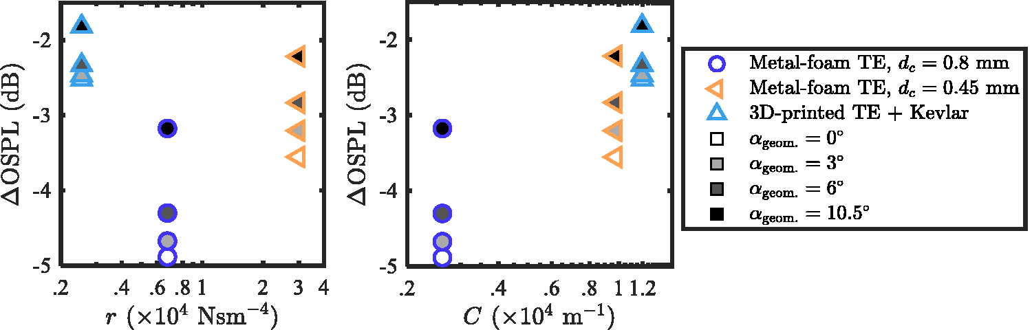
Noise attenuation of the airfoil with various permeable TE inserts at the chord-based Reynolds number of Rec = 4.6
Maximum noise attenuation variability with the geometrical angle of attack of the airfoil with various permeable TE inserts at various chord-based Reynolds numbers as functions of the flow resistivity (left) and the form drag coefficient (right).
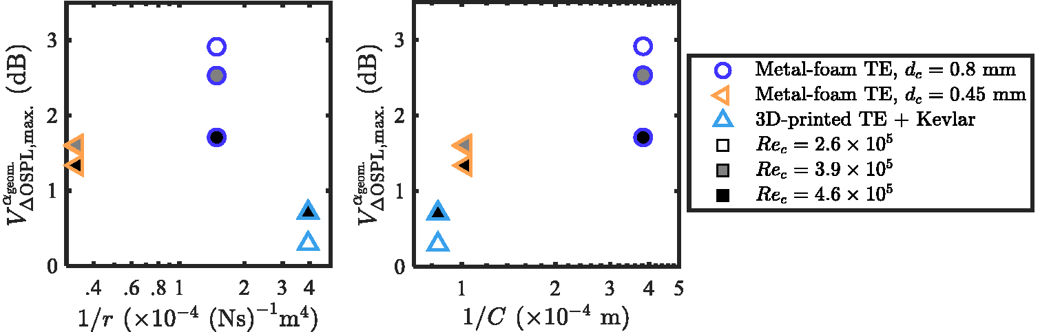
Following the same format as Figure 12, Figures 13 and 14 relate the material properties to the maximum noise attenuation variability with
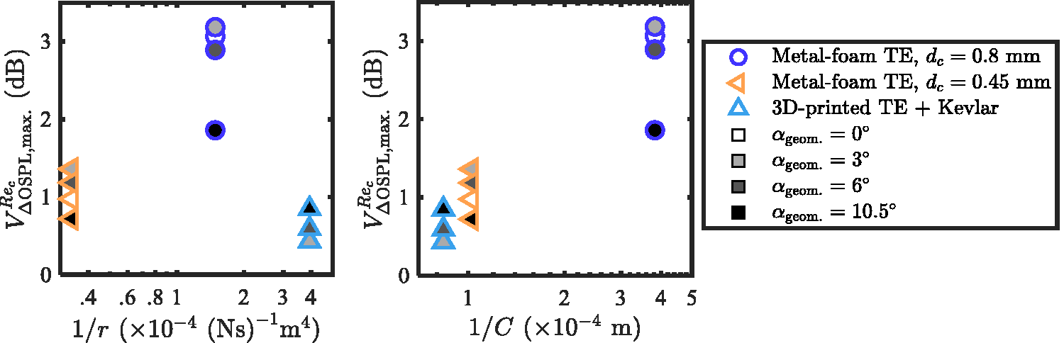
Maximum noise attenuation variability with the chord-based Reynolds number of the airfoil with various permeable TE inserts at various geometrical angles of attack as functions of the flow resistivity (left) and the form drag coefficient (right).
This section has demonstrated that, while the flow resistivity may be related to the
Therefore, a design implication with regards to the permeable material characteristics could be drawn from this finding. The permeable material topology for the permeable TE should be realized such that a high form drag coefficient C is achieved in order to ensure its low variability of noise attenuation performance. Then, without major alterations to the topology, the overall permeability (inverse of r) shall carefully be increased to maximize the broadband noise attenuation. As an example, for the present Kevlar-covered 3D-printed topology, the latter could be achieved by enlarging the size of the 3D-printed hexagonal voids.
From the material characterization perspective, considering the pressure drop curve in Figure 6 (left), the ‘ideal’ permeable material based on the design implication is represented by any material that provides a slow increase of
Source map analysis
The source maps for the 1/3-octave frequency band centered at 1 kHz, Rec = 2.6
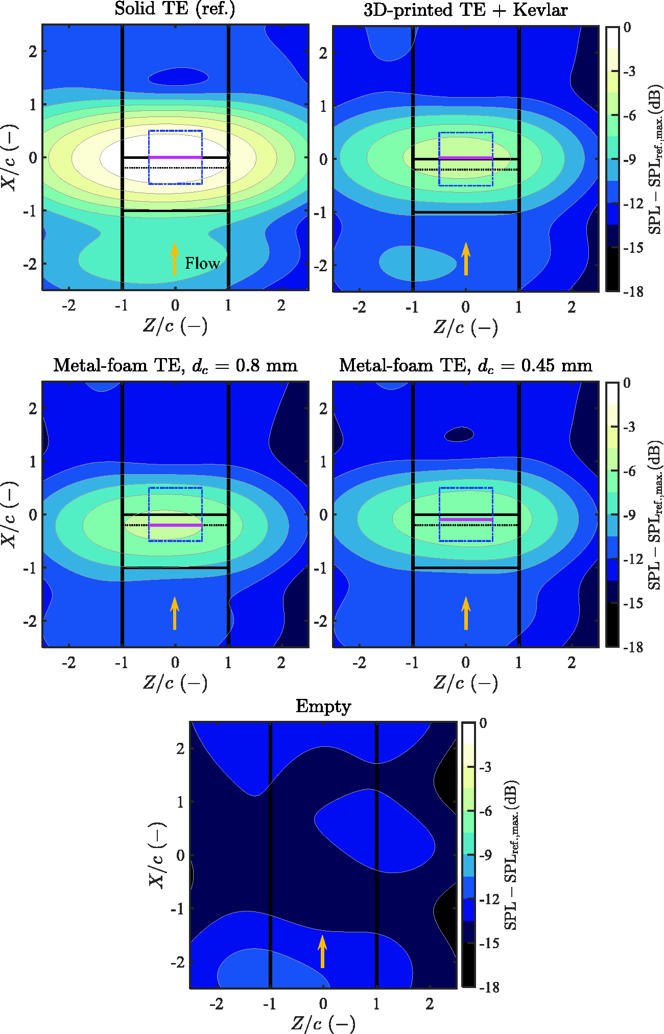
Source maps showing the relative SPL at
The most dominant noise source can clearly be seen around the TE region in all the source maps where the airfoil is present. The relative levels among the maps visualize the TBL-TE noise attenuation as discussed previously. Additionally, the chordwise locations where the maximum SPL is found
Prior to further discussions, it is important to note that the Rayleigh resolution limit at this particular condition is approximately 1.1c, meaning that sound sources with a physical spacing of less than 1.1c cannot be discerned. This distance is much larger than the TE insert extent of 0.2c. Therefore, one must not deduce that the noise source seen is the only actual source. However, all the presented cases are subjected to the same uncertainty, and the apparent source localization shown in the maps still gives a good implication of the chordwise location where the noise scattering is dominant. Thus, relative comparisons of these locations among the different cases are still valid.
For the solid TE, the dominant noise source appears to align with the trailing edge. However, the dominant noise source appears to shift upstream to a location close to the junction between the solid and the permeable extents of the airfoil for the metal-foam TE cases. The distance with which the dominant noise source shifts upstream for the metal-foam TE cases seems to increase with the increasing dc, i.e. permeability. The observation confirms what has been reported in a previous study, 21 suggesting that scattering of noise on metal-foam TE inserts is distributed along the TE insert, resulting in a relatively weaker scattering at the edge. On the other hand, for the Kevlar-covered 3D-printed TE case, the dominant noise source still appears to be at the trailing edge in a more similar way to the solid TE case. This suggests that, although noise scattering along the permeable Kevlar-covered 3D-printed TE insert may exist, the noise still scatters most dominantly from the trailing edge.
To broaden the observation, the plots in Figure 16 show the averaged chordwise distance where the maximum SPL is found,
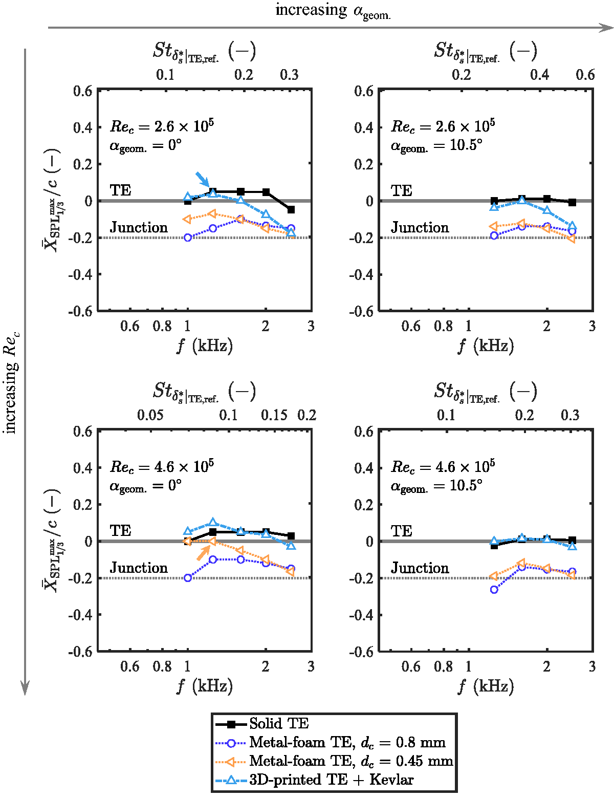
Streamwise locations of the maximum SPL from the source maps per frequency at different combinations of chord-based Reynolds numbers and geometrical angles of attack relative to the locations of the trailing edge (TE) and the junction between the solid and the permeable extents of the airfoil.
For the solid TE case,
The trend still holds for
Therefore, localization of the dominant sound source could again be linked to the ability of the permeable material to withstand the pressure gradient, characterized by the form drag coefficient C. To confirm this, Figure 17 shows the averaged streamwise location at the frequency where the maximum noise attenuation (ΔSPL) is obtained
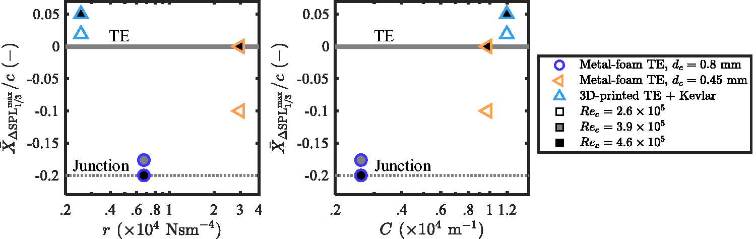
Streamwise locations of the maximum ΔSPL given by various permeable TE inserts at various chord-based Reynolds numbers at zero-degree geometrical angle of attack as functions of the flow resistivity (left) and the form drag coefficient (right).
By examining the locations of the dominant noise scattering source with respect to the frequency, an observation can also be made regarding the roughness noise. Figure 16 is arranged in accordance with Figure 9. For the permeable TE cases at high frequencies, it is notable that the frequency at which the
Drag coefficients
The wake profiles measured by the wake rake at a distance of 2c downstream of the airfoil trailing edge along a 0.5c spanwise traversing distance are shown in Figure 18. The profiles are shown in terms of the measured dynamic pressure deficit, where the dynamic pressure is defined as the difference between the total pressure H and the static pressure p. The subscripts w.r. and
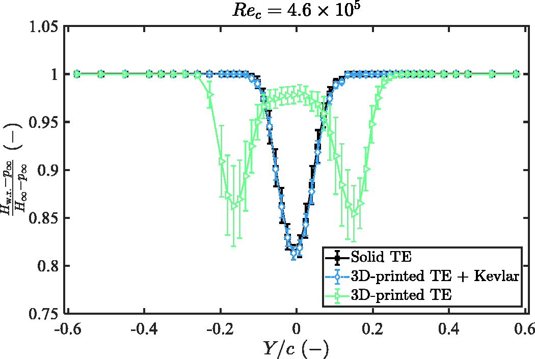
Wake profiles captured downstream of the airfoil with different TE inserts at
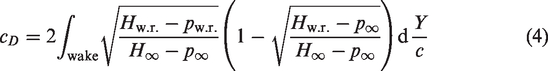
Notably, the wake profile downstream of the airfoil with the 3D-printed TE insert without the Kevlar sheet shows two regions with dynamic pressure deficit: downstream of the suction and pressure sides of the airfoil. The regions with the dynamic pressure deficit are likely to result from vortices travelling downstream. In addition, the relatively high deviations suggest that the two regions with the dynamic pressure deficit may probably not exist at the same instance of time. Instead, the dynamic pressure deficit region location alternates between positive and negative Y/c, i.e. downstream of the suction and the pressure sides. Combining this speculation with the previously discussed tonal noise generation unique to this TE insert case, the wake profile strongly suggests existence of the vortex shedding1,18,31 starting from the junction between the solid and the permeable parts of the airfoil. In turn, cD cannot be derived from the momentum deficit in the wake for this particular case due to this unsteadiness. For the remaining cases, the drag coefficient for any given spanwise measurement location is calculated by integrating the momentum deficit (written in terms of the measured pressures) across the wake as48,52,53
The box plots in Figure 19 show the measured drag coefficients for all the TE insert cases considered and all Rec collected along the spanwise traversing range of the wake rake. The geometrical angles of attack are
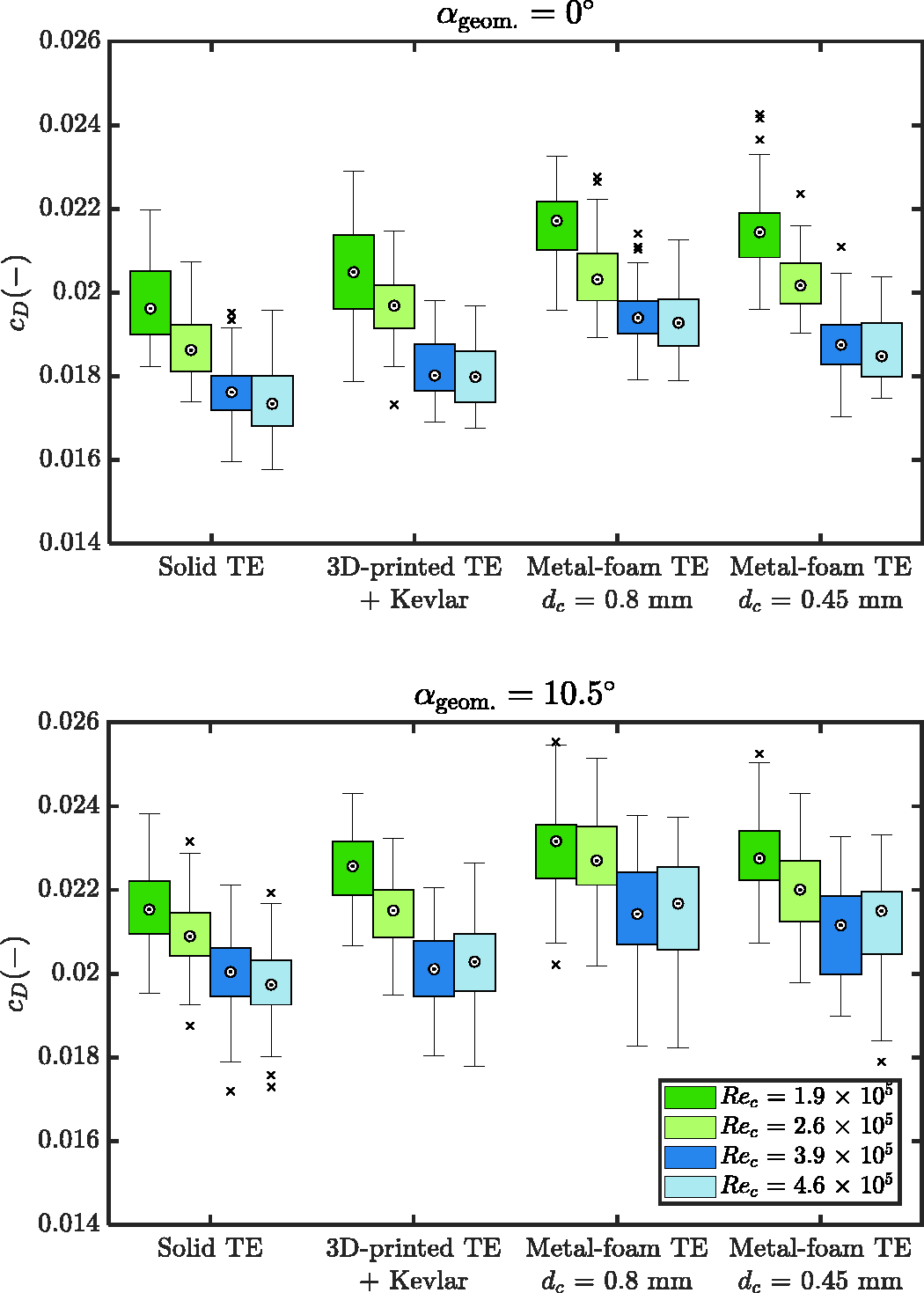
Drag coefficients of the NACA 0018 airfoil with various TE inserts for four different chord-based Reynolds number and geometrical angles of attack of 0
Summary and derivation of permeable TE insert design concept
The noise attenuation and drag results are combined in Figure 20 where scatter plots of the drag coefficient cD and the difference of the Overall A-weighted Sound Pressure Levels (OASPL), ΔOASPL, of every TE insert case for
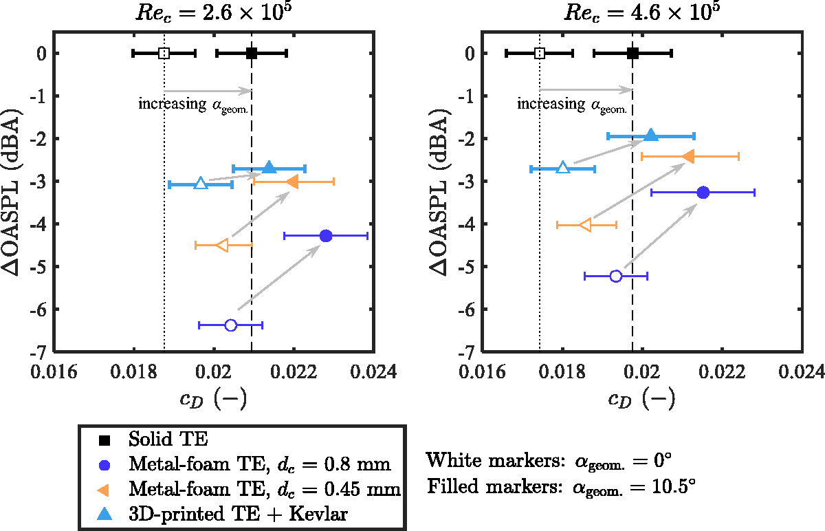
Comparison of noise attenuation and drag coefficients provided by all the permeable TE inserts at different combinations of the chord based Reynolds numbers and geometrical angles of attack.
By taking into account all the findings discussed so far, a general design guideline for the permeable TE insert topology is derived in Figure 21. This concept features a low-roughness surface treatment which has been proven to help mitigate the surface roughness noise and the friction drag increase. In addition, across the TE insert, a combination of a low flow resistivity r for maximal broadband noise attenuation and high form drag coefficient C for minimal variability of the noise attenuation with
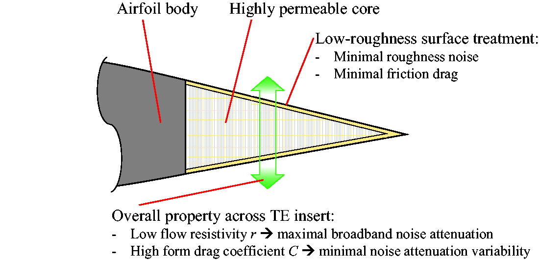
Proposed TE insert design concept for TBL-TE noise attenuation based on findings in the present study.
Conclusions and outlook
This paper studies an approach of turbulent boundary layer trailing-edge (TBL-TE) noise mitigation by integrating a simple permeable topology design concept represented by the Kevlar-covered 3D-printed structure into the trailing edge of an airfoil. An experimental study in an open-jet anechoic wind tunnel featuring a NACA 0018 airfoil with a TE insert made of the Kevlar-covered 3D-printed perforated structure was carried out. The results have been compared to those for the same airfoil with a solid TE insert and conventional porous metal-foam TE inserts. The chord-based Reynolds number Rec was within
Characterization of the Kevlar-covered 3D-printed permeable topology has shown that the present topology gives an unconventional combination of flow resistivity r and form drag coefficient C. Unlike other conventional permeable materials of which C increases gradually with increasing r, the Kevlar-covered 3D-printed permeable topology gives a drastic increase of C (the highest value among all the permeable materials tested) while the value of r is minimal.
The Kevlar-covered 3D-printed TE provides a broadband TBL-TE noise reduction up to approximately 5 dB as compared to the reference solid airfoil. Although the reduction is not as much as that achieved by the porous metal-foam TE inserts, the reduction is found in a wider range of frequency considered. This is the consequence of the Kevlar sheet exhibiting negligible surface roughness as compared to the metal-foam surface. Apart from the mitigation of the roughness noise, the Kevlar sheet is also found to play an important role in mitigating the tonal noise. This finding suggests that a permeable material with a low r can still be employed as a TE insert for an airfoil without a risk of producing the tonal noise, as long as C is large enough.
Unlike the airfoil with the porous metal-foam TE inserts of which the noise attenuation capability varies strongly with increasing airfoil loading, the airfoil with the Kevlar-covered 3D-printed TE insert clearly gives a lower variability. Within the range of Rec and
When relating the characterized permable material properties to the noise attenuation and its variability, it has been found that, when different permeable topologies are compared, the form drag coefficient C shows a clearer relation to those aeroacoustic behaviors than the resistivity r. The broadband noise attenuation as well as the noise attenuation variabilities are found to vary inversely with C. Additionally, analysis of the source maps has also shown the dominant noise scattering source shifts further away from the solid-permeable junction when C of the permeable material increases.
Lastly, the drag coefficients provided by the airfoil with the Kevlar-covered 3D-printed TE insert is significantly lower than that provided by the metal-foam TE inserts due to the relatively lower surface roughness. In many cases, especially at high Rec and
The aeroacoustic findings, in combination with their links to the material properties, have led to a design guideline for a permeable TE insert topology for TBL-TE noise attenuation. The features that the design needs to fulfill are:
In the direction linking the suction and the pressure sides, the permeable material shall have a combination of a low flow resistivity but a high form drag coefficient to achieve maximal broadband noise attenuation while having a low variability of noise attenuation with the airfoil loading. The surface roughness of the permeable insert shall be negligible, compared to the solid extent of the airfoil, in order to have a minimal increment of the friction drag as well as the roughness noise.
When these requirements are fulfilled, a promising trade-off between the noise attenuation and the aerodynamics penalty, i.e. drag increase, is obtained. Apart from the significantly low surface roughness, noise attenuation by a topology as such also appears to be less sensitive to the increasing airfoil loading, compared to the conventional porous metal foams. A simple permeable material combination such as the Kevlar-covered 3D-printed permeable structure considered in this paper could be one, but indeed not only, possible realization to fulfill those requirements.
Crucial elements for future studies include realization of strong, yet highly permeable, topologies and materials for the inner part of the proposed TE insert design concept. In addition, performance of the proposed concept on a realistic wind turbine to verify its noise attenuation capability as well as effects of the streamwise permeable TE insert length on both aerodynamic and aeroacoustic performances shall also be investigated.
Footnotes
Acknowledgements
The authors would like to acknowledge Alejandro Rubio Carpio and Reza Hedayati for sharing the permeable TE inserts and material samples.
Declaration of conflicting interests
The author(s) declared no potential conflicts of interest with respect to the research, authorship, and/or publication of this article.
Funding
The author(s) disclosed receipt of the following financial support for the research, authorship, and/or publication of this article: This work is a part of the Innovative PERmeable Materials for Airfoil Noise Reduction (IPER-MAN) project funded by the Netherlands Organisation for Scientific Research (NWO) and the associating users, project number 15452.