
Abstract
Additive manufacturing has allowed for the production of complex and mass customized geometries, but often at the expense of mechanical performance, a penalty which can be in part mitigated with the fabrication of composite parts. Thermoplastic structures fabricated with material extrusion additive manufacturing stand to be improved in terms of fracture toughness with the integration of continuous fibers. The present research program has investigated the production of a continuously reinforced filament to be used in open-source fused filament fabrication systems. Three different volume fractions of Kevlar fibers were incorporated into a polylactic acid (PLA) thermoplastic filament. It was observed that a 20% fiber volume fraction resulted in a doubling of the tensile strength relative to the unreinforced PLA parts. High-velocity impact tests were also performed on the reinforced printed thermoplastic material, and it was observed that the composite with the highest fiber volume fraction provided an impact energy resistance improved by a factor of four, relative to the plain PLA. The reinforced fibers have shown to restrain the penetration of the projectile at velocities similar to those that perforated the unreinforced PLA. The present work has demonstrated the production of printed composites without the need of modifying the extruding systems of a commercial 3D printer. This approach could represent an alternate and feasible process for producing continuously reinforced 3D-printed thermoplastic parts with utility for high-velocity impact applications.
Introduction
Across the different additive manufacturing technologies currently used, the material extrusion 1 or fused filament fabrication (FFF) process has delivered impressive commercialization success due to the low cost, versatility of material, and ease of use. The initial purpose of FFF units concentrated on manufacturing prototypes for demonstration models. However, these parts presented serious mechanical limitations due to the nature of the polymers used. 2 Further progress in the FFF technology resulted in the production of parts based on materials such as polyetherimide or polyetheretherketone which yielded structures with superior mechanical properties 2,3 but required heated build envelopes. Additional work was performed on FFF systems by incorporating reinforcing particles or short fibers in the plastic filaments to produce parts with better mechanical and thermal properties. 4 –6 It has been shown that the incorporation of short fibers in printed materials enhances their tensile and flexural strength and modulus, adds dimensional stability during printing as well as reduces warping. 7 However, the inclusion of short reinforcing fibers limits their dynamic performance under low-velocity impact conditions—a feature that appears to be related to the embrittlement of the parts due to the incorporation of stiff short fibers. 8 An in-depth discussion of the features, advantages, and progress performed on the fabrication of short fiber-reinforced polymers via 3D printing has been addressed and reviewed by Brenken et al. 9
To produce high-performance materials that are in high demand for sectors like maritime, aerospace, or automotive; the parts need to be constituted by continuously reinforced fibers. 10 The production of 3D-printed continuous fiber composites can be mainly summarized by the following approaches: in-nozzle impregnation of fibers and dual nozzle extrusion of a matrix and fibers. In the in-nozzle impregnation, a neat polymer matrix coats dry fibers during the extrusion-printing process. 11 –13 While successful printed parts have been achieved through this technology, many systems incorporate a mechanical cutting device to cut the fiber and allow the print-head free movements. 13 It is also difficult to print support material without continuous fiber reinforcement, and considerations must be made to ensure the deposition of molten plastic and fiber reinforcement is balanced. 14 Additionally, significant modifications have to be incorporated to the extruding head. 15 In the case of the two nozzles process, one nozzle prints the plastic phase and the other the continuous fiber (both dry or prepregged fibers). 15 –23 However, this technology mainly needs the acquisition of a specific costly FFF printer, such as those machines produced by Markforged (Watertown, Massachusetts, USA). 18,24 –27 Another technology is the incorporation of a continuously reinforced filament on a single nozzle extruding printer. While this approach does not require an extensive modification of the printer, and seems to be both effective and cost saving, it carries the limitations of using an open-source FFF unit, difficulty on printing support material without fibers, and the need of a fiber cutting blade.
Undoubtedly, relevant research has shown the incorporation of continuous fibers (glass, carbon, aramid, or natural) reinforcement in thermoplastic matrices results in superior mechanical properties. Heidari-Rarani et al. 12 investigated the production of continuously reinforced polylactic acid (PLA) parts using carbon and jute fibers with a fiber volume fraction of 6% and reported a greater tensile strength and modulus than that observed on plain thermoplastic materials. Other research groups using either carbon, glass, or aramid fibers on PLA, nylon, and acrylonitrile butadiene styrene (ABS) 13 –15 have reported similar results. Li et al. 19 achieved a fiber volume fraction of 34% of continuous carbon fiber on PLA; however, they reported a strength of 91 MPa, a value that was lower than the one reported by Tian et al. 20 in a similar composite system based on 10% fiber volume fraction. This low mechanical performance could be associated with a lack of fiber wetting from the PLA. Yang et al. 21 reported similar observations on a carbon fiber ABS composite. Van Der Klift et al. 19 have reported that a high degree of fiber–matrix bonding results on 3D-printed composites with a tensile strength higher than aluminum. Tian et al. 20 investigated the printing parameters of continuous composites and reported that controlling the printing temperature, layer thickness, and hatching space results in a direct influence on the fiber volume fraction and the mechanical performance of the composites.
Most relevant to this research is the comparison of composite parts fabricated with continuous Kevlar or aramid fibers in a PLA matrix. The use of in-nozzle impregnation seems to be the most popular method for producing these parts. 17,28 Bettini et al. examined a composite of aramid fibers and PLA based on a fiber volume fraction of 8.06% and reported a tensile strength considerably greater (203 MPa) than the unreinforced PLA matrix (34 MPa). 17 In a similar PLA printed system with Kevlar fibers based on a volume fraction of 6.54%, Tey et al. 28 measured an ultimate tensile strength of 104.64 MPa. A value that was significantly higher than the recorder on the unreinforced matrix (37.41 MPa).
Another benefit of incorporating continuous fibers into a thermoplastic matrix is the improvement of impact energy absorption of the composite material, compared to its unreinforced counterpart. One of the promising applications of these 3D-printed composites will be on the ballistic body armor protection field. Here, additive manufacturing can provide bulletproof vests with customized configurations and conformations. The use of a high-velocity projectile for characterizing the ballistic performance of reinforced composites is a widely used procedure followed elsewhere. 29 –31 Typically, a ballistic round is fired until the specimen fractures, indicating the maximum perforation energy.
In contrast to the broadly investigated methods of 3D printing continuous fiber systems (dual nozzle or in-nozzle impregnation of fibers), this work creates for the first time a coaxial filament that can be printed through a single nozzle. In this work, PLA was selected as the matrix phase of the reinforced filament due to its wide employment and easy availability. The present article has investigated the production of a continuously reinforced Kevlar–PLA filament and its processing on an open-source 3D FFF printer for manufacturing reinforced composites. Here, the static performance and the dynamic performance of the printed composites were evaluated and compared to the unreinforced counterpart. In addition, ballistic testing was performed on the 3D-printed composite to characterize the high-velocity impact properties of the Kevlar and PLA matrix.
Experimental methodology
Materials and 3D printing
In this research program, DuPontTM Kevlar fibers (Wilmington, DE, USA) of total tex 40, 69, and 346 g/1000 m were obtained from Superior Threads (St. George, Utah, USA). Here, the volume fraction of the manufactured composite filament was increased by incorporation of a thicker fiber bundle (i.e. higher threads were used to obtain a higher volume fraction in the manufactured filament). The smaller tex fiber, 40, was a dry spun Kevlar, with an average bundle diameter of 0.195 mm, whereas the larger tex fibers, 69 and 346, consisted of 3 tows of fibers spun together, having bundle diameters 0.25 mm and 0.65 mm, respectively. Kevlar fibers #69 and #346 were bonded Kevlar, covered in a proprietary coating from the manufacturer. The tested tensile properties of the Kevlar fibers and PLA matrix are given in Table 1. PLA pellets purchased from Filabot (Balle, Vermont, USA) were used for the thermoplastic matrix.
Mechanical properties of materials used on this research program.a

PLA: polylactic acid.
a Included in parenthesis is the standard deviation.
A modified polymer extruder from Filabot was used to coaxially incorporate a continuous Kevlar fiber bundle within the PLA matrix (see Figure 1). In this process, the outer diameter of the extruded composite filament was kept constant while the volume fraction was increased by the incorporation of different fiber bundles diameters (Table 1). The aforementioned virgin polymer pellets and Kevlar fiber bundles were passed through the extruder with a 1.5-mm nozzle diameter at 180°C, at an extruding rate of 80 mm/min, cooled using fans, and collected by an automatic spooling system. This process yielded a 1.75 mm diameter fiber-reinforced filament.
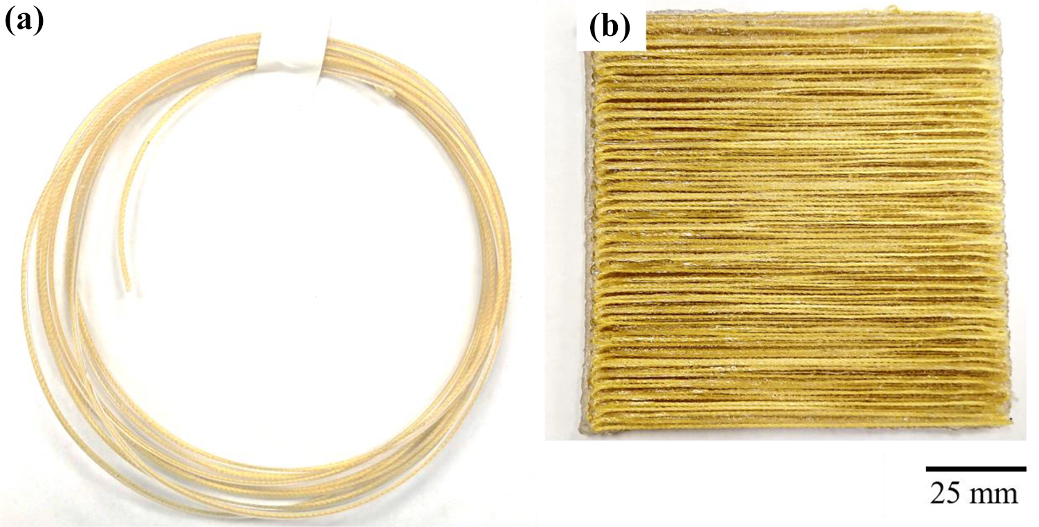
Images of the continuously reinforced material produced in this work. (a) Continuously reinforced filament (Kevlar #346). (b) Composite sample printed with the continuously reinforced filament (Kevlar #346).
Following the extrusion of the filament, a MakerGear M2 open-source FFF unit was used to manufacture composite samples. The 3D printing was performed through a 1-mm nozzle at a temperature of 210°C, at a speed of 1 mm/s. The bed temperature for the PLA and Kevlar prints was 80°C.
In general, the nozzle of the 3D printer traverses the printing bed in established noncontinuous motions in the (X–Y) plane on open-source FFF slicing software. However, when printing continuous fiber-reinforced filaments, the motion in the X–Y plane must be specific, controlled, and uninterrupted to avoid breaking or damaging the fiber during the printing. Thus, in this work, custom .stl files were generated in Fusion 360 (San Rafael, California, USA) to force the motion of the nozzle in a continuous travel path. Figure 2 shows the travel paths of the extruder in a default mode (top) and in a single continuous line path (bottom) required for continuous-reinforced printing. Additionally, to avoid tearing and breaking of the fiber during the printing process, an extrusion multiplier of 1.9 was used on the unit, effectively increasing the flow of filament through the nozzle by 190%.

3D printing slicer generated travel. Noncontinuous standard stl (top). Customized continuous path (bottom). The arrows show the printing path.
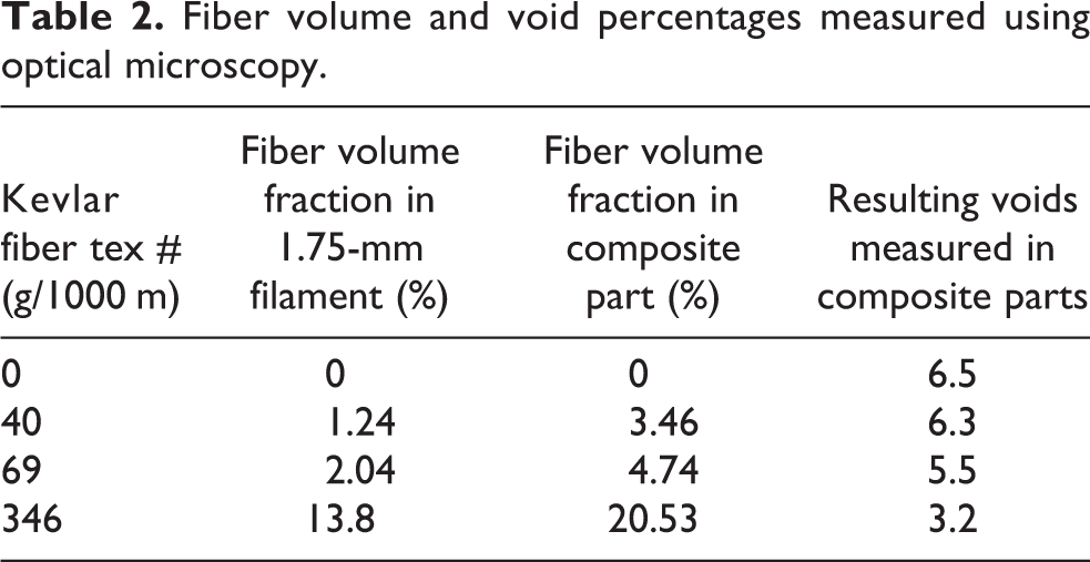
Cross-sectional images of the manufactured parts were utilized to determine the porosity of the printed specimens as well as the volume fraction of fibers in the printed composite parts. The cross-sectional images were evaluated using the open-source image processing software ImageJ (1.52a). The area of the voids was measured and reported as a percentage of the total cross-sectional area (see Table 2). While all other processing parameters remained the same (layer height, nozzle diameter, and printing speed), a decrease in the void content was observed as the volume fraction of fiber reinforcement was increased. The incorporation of higher tex fiber bundles resulted in a wider bead of extrusion from the printer, resulting in a lower void fraction of the final printed part.
Fiber volume and void percentages measured using optical microscopy.
Mechanical testing
In this work, unidirectional tensile specimens were printed using a rectangular geometry and tested based on the ASTM D3039 methodology. The test was performed in a universal Instron machine (Norwood, Massachusetts, USA) at room temperature, at an extension rate of 2 mm/min. Stress data were collected from a 150-kN load cell. Four samples were tested with fibers oriented in the longitudinal direction to investigate the tensile properties of the printed systems. Additionally, to more accurately determine the Young’s modulus, and failure point of the manufactured samples, three samples were tested at the same extension rate, but with the assistance of an extensometer to measure the strain of the samples. Similarly, four rectangular test specimens, following the ASTM D7264, were prepared for three-point bend testing to obtain the flexural properties of the material. As in the tensile tests, the Kevlar fibers in the flexural specimens were oriented in the longitudinal direction.
Additionally, square specimens of 100 × 100 × 5.5 mm3 (W × L × T) were printed for high-velocity impact testing. As there is no significant increase in mechanical properties measured on the lowest volume fraction (Vf = 3.36%), only the higher volume fraction samples with both unidirectional and cross-ply (0°/90°) orientations were selected for impact testing (Vf = 4.74%, 20.53%). The incorporation of a cross-ply configuration for the high-velocity impact testing was due to their superior performance over unidirectional systems, which tend to simply split when hit by a projectile. 32 The high-velocity impact testing consisted of a nitrogen gas-gun assisted by a chronograph for measuring the impact velocity. The samples were impacted with an 8-mm steel ball (2.05 g) from low-velocity impact conditions (20–30 m/s) up to their perforation event, by gradually increasing the impact velocity in increments of 50 m/s. The tested samples were clamped in a steel bracket (Figure 3). The high-velocity impact properties were determined utilizing the impact energy required to break the sample, which was calculated using equations (1) and (2).

High-velocity impact testing area of the nitrogen gas gun. Samples were clamped on a steel bracket. A new sample was used on each impact testing.
Impact energy, Ek, was determined by the general kinetic equation

Here, the specific perforation energy was also determined by dividing the kinetic energy by the areal density
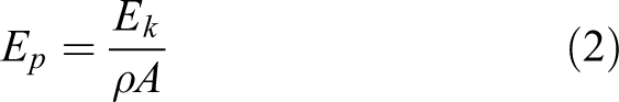
where the areal density, ρA, is obtained by dividing the mass of the sample over the cross-sectional area.
Results
Microscopy
The cross-sectional area of the printed parts was observed in both optical and scanning electron microscopes to elucidate the fiber–matrix interaction. Figure 4 displays the cross section of printed composites for each volume fraction studied. From the figure, it was observed that a relatively good degree of interfacial interaction between the matrix and the Kevlar was achieved for the composite based on Kevlar #40 (Vf = 3.46%). However, the Tex #69 and #346 Kevlar (Vf = 4.74% and 20.53%, respectively) displayed a marked fiber–matrix debonding. Indeed, Scanning electron microscopy (SEM) analysis of the #346 fiber shows distinctive lack of bonding between the bundle of fibers and the matrix. These results indicate that the use of uncoated Kevlar bundles yields printed composites with superior fiber–matrix adhesion.

Optical and scanning electron micrographs of the composite parts created in this work. (a) Vf = 3.46% Kevlar, (b) Vf = 4.74% Kevlar, and (c) Vf = 20.53% Kevlar.
Tensile properties
The tensile results of the investigated systems are shown in Figure 5 and summarized in Table 3. From the figure, it was observed that increasing the volume fraction of Kevlar fiber in the matrix resulted in a composite with a superior tensile strength. While these values appear to be in the range of strength reported in other studies for the composites composed of 3.46, and 4.74% volume fraction, the composite based on the fiber volume fraction of 20.53% yielded a tensile strength of 84.1 MPa, a value two times higher than that observed on the plain PLA. However, a strength of 84.1 MPa is 71% lower than the tensile strength reported by Bettini et al., 17 for a volume fraction of only 8.6%. This, in addition to the lower Young’s modulus observed in the sample containing a volume fraction of 20.53%, suggests that a better matrix fiber adhesion is needed to improve the mechanical properties of these systems. Indeed, it is expected that an optimized extrusion process and an enhanced fiber–polymer adhesion can improve the properties of these printed composites.
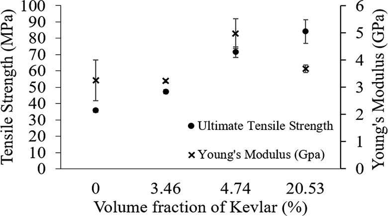
Tensile strength of the plain PLA and Kevlar-reinforced PLA. PLA: polylactic acid.
Tensile properties of the manufactured Kevlar/PLA composite materials.
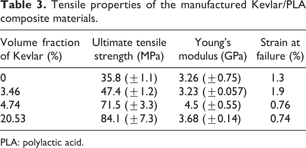
PLA: polylactic acid.
A further examination of the fractured specimens after the tensile tests suggested a lack of matrix–fiber adhesion specifically on the samples containing 4.74% and 20.53% volume fraction (see Figure 6). The figure shows a bundle of dry fibers after the fracture process; an indication of a limited fiber–matrix interphase. These results support the low values of strain at failure reported in Table 3 on the composites based on 4.74% and 20.53%. Indeed, the lack of an enhanced matrix–fiber bonding affects the load-displacement transfer between phases. It seems that the proprietary coating applied to the Kevlar fiber by the supplier diminishes its adhesion to the PLA system. In contrast, the sample containing uncoated Kevlar fibers, with a volume fraction of 3.46% (Figure 6(a)), shows broken fibers throughout the fracture area suggesting a relatively strong fiber matrix bonding.

Fractured composite samples after uniaxial tensile test for each of the three volume fractions observed (a) Vf = 3.46% Kevlar, (b) Vf = 4.74% Kevlar, and (c) Vf = 20.53% Kevlar.
Flexural tests
The flexural strength of the investigated samples is shown in Figure 7. Here, it is observed that increasing the volume fraction of Kevlar fiber in the PLA resulted in an increase in the flexural strength. The figure shows that increasing the volume fraction of the Kevlar up to 20.53% resulted in almost 24% increase of the flexural strength when compared to the plain PLA. However, this increase in flexural strength as a function of the fiber volume fraction is not as pronounced as examined under the tensile testing conditions.

Flexural strength of the reinforced Kevlar composites and the PLA printed samples. PLA: polylactic acid.
The summary of the flexural modulus, flexural strength, and standard deviation of the examined samples is provided in Table 4. As it can be observed, the flexural properties of these manufactured composites seem to be governed by the PLA matrix, showing a limited increase in the flexural strength of the composites. No significant difference was found in the measured flexural strength or flexural modulus of the reinforced composites. This has been attributed to the inhomogeneous distribution of fibers within the matrix and the brittleness profile of the PLA. Optical analysis on the fractured samples after the flexural testing showed that the PLA in the composite failed before the fibers were broken (see Figure 8). Included in Figure 8 is a tested sample based on plain PLA under flexural conditions, where the typical brittle fracture of the PLA is displayed.
Flexural properties of the manufactured Kevlar/PLA composite materials.

PLA: polylactic acid.

Fractured flexural samples. Plain PLA (top) and Kevlar #69 reinforced PLA (bottom). PLA: polylactic acid.
Impact testing
The high-velocity (56.7–174 m/s) impact testing of the materials investigated is shown in Figure 9. From the figure, it is observed that increasing the volume fraction of Kevlar fiber in the composite resulted in a superior impact performance. Indeed, the printed composites based on 4.74% and 20.53% volume fraction of Kevlar in the unidirectional orientation resulted in a perforation energy of 1.4 and 3 times higher than the values recorded on the plain PLA material, respectively. Further impact enhancement was observed on the composites based on a cross-ply arrangement. Here, the aforementioned composites yielded a perforation energy of more than 2.3 and 4.4 times higher than the observed on the plain PLA, respectively.
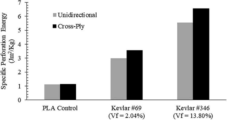
Specific perforation energy of the plain PLA and Kevlar-reinforced composites. PLA: polylactic acid.
The plain PLA samples had an areal density of 6.3 kg/m2, while the composites showed a value of 5.2 and 4.8 kg/m2 for the Kevlar #69 and #346, respectively. The graph shows that the composite based on a fiber volume fraction of 4.74% (Kevlar #69) yielded a higher impact energy than recorded on the plain PLA composite. It is also observed that the composites based on the highest volume fraction (Kevlar #346) shows the highest specific perforation energy (6.56 Jm2/kg). The impact performance of these 3D-printed Kevlar composites seems to be superior to the impact energy recorded on continuously printed carbon fiber-reinforced ONYX laminates with similar thickness. 24 Figure 9 shows that the cross-ply composites resulted in a greater impact performance than the unidirectional composites. A mechanism that seems to be associated with the lack of reinforcement in the 90° on the unidirectional composites. 32
Optical analysis of the impacted composite samples unveiled several differences from the unreinforced counterparts. Figure 10(a) to (c) shows the optical characterization of an impacted composite sample, where it is apparent most of the impact energy was absorbed by the Kevlar fibers. It was observed that the cross-ply orientation of the fibers resulted in out-of-plane deformation of the reinforcing layer (Figure 10(c)). Included in Figure 10 is a plain PLA sample following the high-velocity impact testing (Figure 10(d)). It should be noted that the unreinforced composite displayed no out-of-plane deformation and instead showed a typical brittle failure. Figure 10(b) shows the Kevlar fibers did not exhibit a presence of matrix material through the fracture area, suggesting once again that a better fiber wetting process for improving the interfacial matrix–fiber adhesion needs to be incorporated when producing these composites.

Impacted printed samples under high-velocity conditions. (a) Kevlar #346, (b) frontal magnification of the impacted area, (c) side view of the impacted zone, and (d) plain PLA. PLA: polylactic acid.
Conclusions
In sum, this research has gathered the following conclusions for the production of continuous fiber-reinforced composites via additive manufacturing: Using an open-source FFF 3D printer, it is possible to manufacture composite parts with a single nozzle and coaxial continuous fiber/matrix filament. The resulting samples showed that the composites based on a volume fraction of 20.53% Kevlar fiber can yield an ultimate tensile strength more than twice that of the unreinforced counterpart. The coaxial filament allowed for continuous fiber-reinforced cross-ply and unidirectional samples to be 3D printed for ballistic testing. High-velocity impact testing showed a significant increase in the perforation energy of the continuous fiber-reinforced materials over their unreinforced counterpart. Bonded (coated) Kevlar fiber bundles contributed to a low wettability and adhesion into the polymer matrix; however, spun Kevlar fibers displayed a good degree of adhesion under optical microscopy.
This work has demonstrated the use of a continuous-reinforced filament for producing printed parts without the need of modifying the extruding components of FFF printers. This process could suggest an alternate and feasible approach for manufacturing continuous-reinforced 3D-printed composites.
Footnotes
Acknowledegment
The authors would like to thank the PhD candidate Bhargavi Mummareddy for her assistance in SEM analysis of samples.
Declaration of conflicting interests
The author(s) declared no potential conflicts of interest with respect to the research, authorship, and/or publication of this article.
Funding
The author(s) received no financial support for the research, authorship, and/or publication of this article.