
Abstract
In recent years, there has been new interest in understanding the mechanical failures of the polymer-composites used for fairing the hull and the superstructure of large vessels. There aren’t any background studies looking into the failures of these thick coated structures and this study is attempting to bridge the gap in research by studying the monotonic flexural behaviour of these structures to investigate the reasons for its failures. The objective is to study the monotonic flexural behaviour of three popular particulate composite materials used as coatings on megayacht vessels and obtain an initial understanding of their behaviour and interaction with the steel substrate. The methods presented are both analytical and standard testing procedures for the examination of the flexural stress-strain response of the thick polymer-composite coated steel specimens. The results of this work suggest that different failure mechanisms have been observed in the three examined coating systems. It has been shown that the experimental data suggested no significant interaction between the steel and the polymer-composite material. The findings suggest that it is possible to enlarge the design space of the polymer-composite coatings by reducing the applied thickness of the materials. Results also have shown that the presence of voids cause reduction in strength by 20% and reduction in deformation by 30%. The study concluded to a two-step methodology involving analytical and experimental methods investigating the mechanical response of composite polymers applied on hull and superstructure substrates which is presented for the first time in this paper.
Keywords
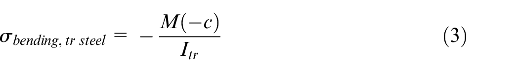
Introduction
This paper investigates the behaviour of three particulate polymer-composites applied on metallic hull and superstructure substrates of yacht structures. The material is part of the coating system of large yacht vessels. Major composite material failure problems have been observed in the last 7 to 10 years. These are industrial failures observed on several large yacht vessels which are not documented nor it is allowed to be disclosed as they are predominantly on private yacht vessels. The failures lead to expensive lawsuit cases which cannot be justified as missing experimental data and expertise on the matter. This study aims to close this gap by providing data of three examined materials used as coatings on mega yacht vessels. The polymer composites examined are two-component epoxy resin systems, including particulate glass reinforcements, pigments and reactive diluents. These materials are mainly used on yacht structures (and also in wind turbine applications and cruise liners), appeared in the market a few decades ago, although major failures arose in the last 5–10 years. A growing trend of numbers of failures was observed as the yacht dimensions were increased from 50–60 m to 200 m in length. Failures on mega-yacht structures have received considerable critical attention by all industries involved in vessel construction, paint/coating manufacture and application. Only a handful of studies attempted to investigate the causes of failure of the particulate composite components used on metallic substrates.
Studies which characterise the constitutive response of the polymer itself are important, and the findings from extensive experimental work will be presented in a different paper. This paper utilises findings obtained from material characterisation tests and compares the material behaviour with the behaviour of the coupled material on a metallic substrate using coated test specimens. Establishing both the constitutive response of the polymers and response of the coupled polymer with steel plates is important in understanding the mechanics of fracture from a macro-level point of view. The mechanical response of polymeric materials bonded or used with dissimilar materials such as fibre reinforced plastic materials and metals is currently a developing topic in engineering.
Nonetheless, there is very little research published on polymer-composites used on yacht structure applications. Recent work from Nebbia et al. 1 describes the compressive and three-point flexural results obtained from examination of different brands of polymer-composites. The flexural behaviour of the polymers was discussed by presenting load-deformation diagrams of polymer backed specimens. Another recent study in the area of the polymer-composite materials, by Giannarelli et al. 2 have examined the influence of temperature on the behaviour of coated steel plates with finite element methods. The difference in thermal properties of polymers and the steel are highlighted. However, the temperature influence on the mechanical response of the materials up to failure is not explicitly stated. Most of these studies have suffered from a lack of well-grounded theoretical considerations in the interpretation of the results. Also, it was observed that changes in polymer thickness and a parametric comparison of their properties and other variables is missing from the literature.
Causal factors leading to failure of polymer composite materials used on yacht structures remain speculative. This indicates a need to investigate the effect of increased composite thickness and the influence of voids and failure mechanisms across different coating systems. The primary aim of this work is to investigate the mechanical response of the polymer-composite materials under quasi-static loading and to contribute to the understanding of their fracture response. A methodology for estimating longitudinal stresses and strains of the composite materials is suggested in this paper.
Relevant literature on bonding dissimilar materials with epoxy-based polymers, such as joint designs and strengthening of metal structures with fibre reinforced composites provided background knowledge to this study and created an opportunity to develop knowledge around the polymer-composites used as coatings. It is well known that composite materials are slowly replacing other materials in engineering sectors such as the civil, marine, mechanical and automotive engineering and others. Previous studies on failures of fibre-reinforced steel structures have been found to be related to the fracture of the epoxy-based adhesive used to bond the dissimilar materials. The polymer is always weak when metals are bonded to fibre reinforced composites. Investigations for improvements of the bond properties and characteristics and fatigue life of FRP reinforced structural components are at the research forefront currently. There are some published studies (e.g. Fuller and Wisnom 3 and Czél et al. 4 ) examining the brittle fracture behaviour and damage suppression of carbon and glass fibre reinforced laminates.
Other researchers, carried out studies investigating the microstructural behaviour of particulate composite materials. Nie and Basaran 5 suggested that a micromechanical model with greater interfacial thickness or reduced interfacial strength between filler particles and matrix would reduce the effective elastic modulus thus improving the overall fatigue life of a particle filled composite.
Several investigations (e.g.Ghassemieh 6 and Bardella et al. 7 ) were focused on interfacial bonds and micromechanics rather than the macro mechanics behaviour of the materials. Lee and Pyo 8 developed an elastoplastic multi-level damage model considering a weakened interface to predict the elastoplastic behaviour of the composites and the damage evolution of the weakened interface in particulate ductile matrix composites used for various engineering applications. According to their work, a gradual and smooth transition from the perfectly bonded interface to the perfectly de-bonded surface results in the nonlinear stress-strain response of the composite. It was also noted, that because of the random levels damage in the microstructure of the composites, the isotropic behaviour is assumed under general loading conditions.
There has been no detailed investigation of the response of thick composites used on metallic substrates of large yacht vessels and the influence of visible voids. The primary objective of this work is to predict the stress-strain characteristics and the macroscopic failure behaviour of the composites. Failure of plastic coating components is now at the forefront of research, with material designers of coating systems becoming more and more interested in understanding the macroscopic behaviour of the applied materials under the in-service load conditions. In general, there is a notable paucity of empirical research in the area of design of coating materials based on their mechanical properties. Hence, the findings of this study will help to understand better and predict the mechanical properties of these composites, creating an opportunity for better-designed products which meet the current market requirements.
Methods
Prediction of the response of a structure and designing against failure under any loading could be complicated especially when the most influencing parameters are unknown. The impact of parameters influencing the ultimate performance of the material can only be determined by performing experiments both on standard specimens of the bulk materials and full-scale tests of the actual components. The experimental programme discussed in this paper is focused on flexural testing of hybrid components of polymer-composites with steel backing plates. Nevertheless, due to the novelty of this work and lack of research data it was essential to initially proceed to the material characterisation of the bulk polymer-composite materials. Tensile, flexural and compressive mechanical characteristics of the bulk materials are included in discussions and comparison of the materials.
Beam testing
The primary objective of this test was to compare the failure modes of three different materials and compare their mechanical characteristics under flexural load. The four-point bend test configuration allowed to examine the bending load effect and neglect the impact of shear over the middle area, which is present with the three-point bend configuration. This is an advantage of the four-point flexure method over the three-point bend method, as it facilitates examination of the component under pure bending. This facilitates the calculations and attainment of clear conclusions by only examining the opening mode of failure.
As can be seen from the experimental setup in Figure 1 the specimen is situated on two roller supports and load is applied by the loading span (via the third and fourth roller on the top). As a result, the four-point bending configuration enables for peak stresses and strains to occur along an extended region of the specimen surface, at the outer fibre surface of the composite material. The tensile stresses occur on the convex side and compressive stresses on the concave side of the beam as can be seen in Figure 1. Another interesting fact is that the strain distribution is a linear and continuous function of the thickness of the bi-material beam, whereas the stress profile is discontinuous through the depth of the beam and a linear function through the thickness of each material.

Thick cross-section (SS20) specimen under pure bending.
Pure bending test characteristics:
Continuous (linear) strain distribution through the depth of the beam.
Discontinuous (linear) stress distribution through the depth of the beam.
Flexural stress: linear function through the thickness of each material.
Flexural strain: linear function through the depth of the component.
The following assumptions are valid for flexural beam testing.
The longitudinal axis of the neutral surface does not change in length.
All cross sections of the beam remain plane and perpendicular to the longitudinal axis during the deformation.
Any deformation of the cross-section within its plane is neglected.
Shift of neutral axis and hybrid beam method
The analytical method described in the sections below is based on composite beam theory, however a new equation is derived and described in section 2. The equivalent area axis method was followed for determination of the position of the neutral axis, and calculations of the longitudinal stress and strain profile of the examined materials. It was essential to initially locate the neutral surface with the equation shown below, where longitudinal fibres will not undergo any change in length.
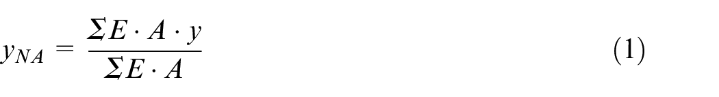
Maximum longitudinal stress on the polymer material component
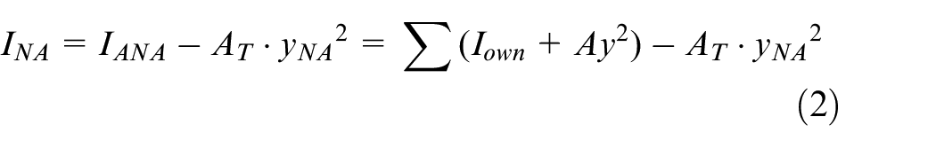
For simplification of the problem, the equivalent area axis theorem was followed for all theoretical calculations and the component examined was transformed to a single material, steel in this instance. The less stiff material area was converted into, the more rigid material (steel) to simplify the calculations. Full interaction of the steel and the applied polymer-composite material is assumed. Thus, the moment of inertia was calculated using the parallel axis theorem is equal to the moment of inertia of the transformed section
Where:
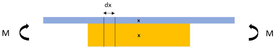
Hybrid composite specimen undergoing flexural load.
The longitudinal stress of the transformed area, at any location
Where:
Figure 3 shows the stress, strain distribution of along the depth of the beam. The maximum longitudinal stress occurs on the outer (fibre) surface of the polymer-composite component (tensile stress of composite is exaggerated for demonstration). This could be estimated by transforming the steel component back to composite. The maximum flexural stress at the outer surface of the composite section is calculated multiplying the above flexural equation by the transforming ratio

Where
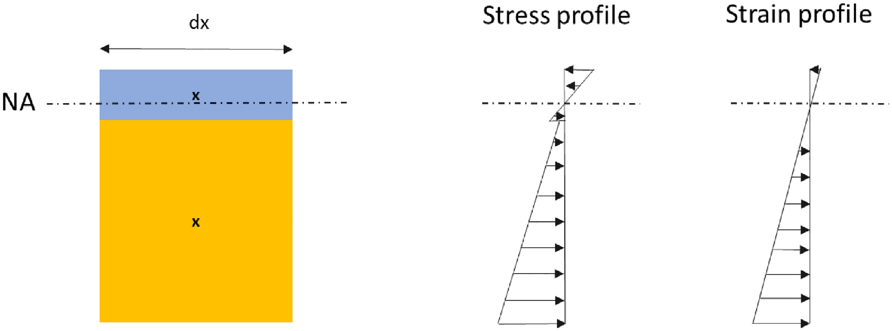
Stress and strain distribution of a strip from bi-material composite beam undergoing flexural loading (diagrams not in scale).
Longitudinal strains of the outer surface of the composite
The flexural strains at the outer fibre surface of the composite material were calculated using the equivalent area axis method. Longitudinal strains are a continuous function through the thickness of the transformed area; thus, for these calculations, it is assumed that the component is still converted into steel.
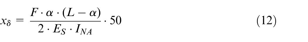
The maximum displacement for the configuration tested and for load span equal to half of the support span occurs at the bottom outer surface of the component and can be estimated from equation (5) below.
The Young’s modulus of the transformed beam (steel)
Thus, the bending stress of the transformed beam (steel) is as follows
By substituting the above relationship for
Where:
The maximum longitudinal strain occurring at the outer surface of the composite material is then calculated using the maximum bending moment calculation
Deflection correction procedure:
Since most of the specimens were tested using the four-point bend configuration, correction needed to be applied to the deflection measurements obtained by the machine. Strain gauges were used for some of the specimens to validate the proposed ‘correction’ method.
In the four-point bend case, the maximum deflection measurements need to be taken from the midsection of the outer bottom surface of the specimen, using a transducer or strain gauges. In the case that deflection is obtained from the machine, a slight error is induced as the deflection is measured at the loading rollers about the lower roller points.
From simple beam theory the deflection angle (
Beam in four-point bending.
From trigonometry the angle
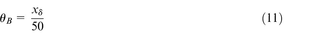
Thus, by combining equations (10 ) and (11) the extra deflection,
Hence the maximum deflection at midpoint of the beam can be calculated by superimposing the deflection at the roller points

It should be noted that the correction of the midpoint deflection is minimal and does not alter the results to any great extent.
Test methods and geometry of specimens
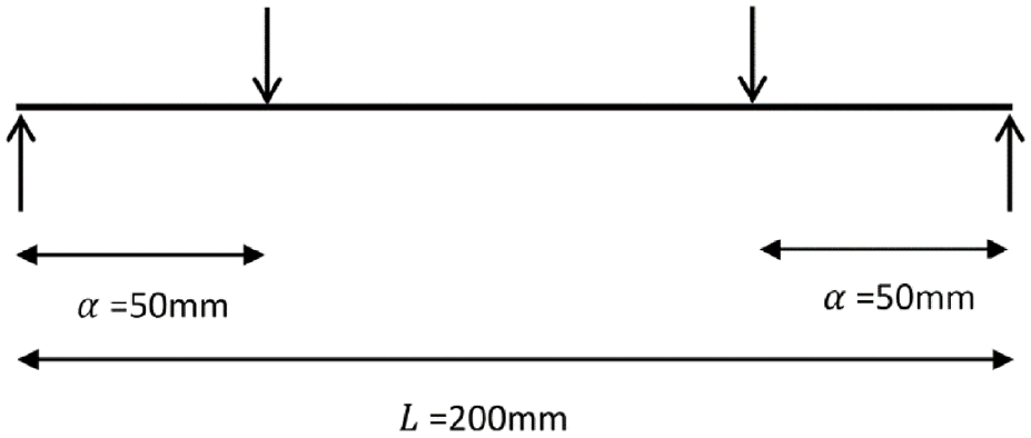
A four-point loading system is used to test the coated test specimen. The tests were performed according to the specifications of the ASTM standard D6272-10. The tests were conducted in displacement control at a speed of 1 mm/min in ambient room conditions (23°C). Load span and support span lengths were defined according to the designed specimens produced for this study.
Twelve test specimens were tested in pure bending. The length of the specimens was 420 mm including the extension beyond the supports. Load spacing of 100 mm and the support spacing of 200 mm were used. The geometry and dimensions of the 20 mm thickly coated specimen can be seen from Figure 1 below. Two different geometries were prepared for each of the three materials tested. As mentioned above, 10 and 20 mm thickly coated steel specimens were tested. The thickness of the steel was selected as 5 mm (an average value of thickness used in ship construction for superstructure).
Selection of materials
Three commercial polymers, namely materials A, B and C with different mechanical properties were chosen for this study. Three of the mostly used (from a total of seven commercially available) materials were selected for examination, to obtain precise conclusions based on their different responses. Each of the materials is comprised of a two-component epoxy resin and curing agent system. The epoxy resin binder component is composed of a mixture of reinforcing fibre particles which add to the toughness of the materials and a mix of pigments and reactive diluents.
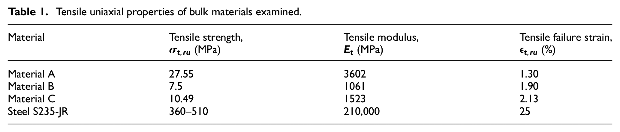
Datasheets with mechanical properties of the epoxy polymers were not available in all cases; bulk tests were carried out to determine material properties. All properties were obtained from specimens without air-voids and defects. Uniaxial and bending tests provided with the mechanical properties of the bulk materials (see Tables 1 and 2). A typical value of the tensile strength of the primer is referenced to be 10 MPa (value determined by industry), although it was not used in the calculations.
Tensile uniaxial properties of bulk materials examined.
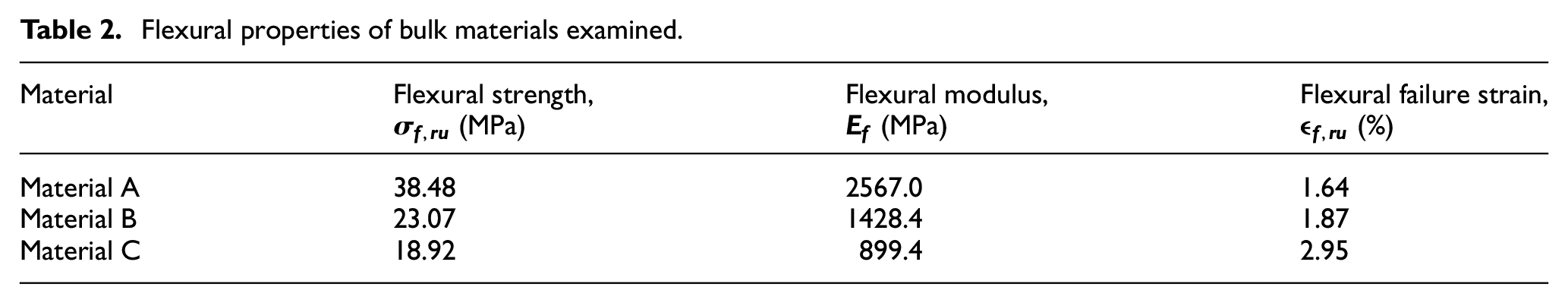
Flexural properties of bulk materials examined.
Production of coated test specimens
All four-point bend specimens were manufactured as applied in real applications on-site. Before application of the coating layers, preparation of the metallic substrate was required to obtain good adherence with the next layers applied. The steel substrate was initially de-greased, and then it was grit blasted until a uniform thickness of the aggregate was achieved. After that, the primer layer was applied using the airless spray at an air-controlled room.
After surface preparation, the polymer-composite was manually mixed and applied in the specially made moulds in thin layers. The cast of the composites in moulds allowed production of identical test specimens. Two types of geometries were produced, specimens with a thick and thin cross-section. The thin cross section has a composite thickness of 10 mm, and the thick cross-section a composite thickness of 20 mm. The 20 mm thickly coated specimen was applied in two 10 mm thick layers by adding a mould plate on top of the first, once the first 10 mm composite layer was cured (for 15 h). Sanding between the applied layers removed accumulated dirt and increased adherence between the layers. All specimens were initially cured in controlled room temperature conditions for 15 h (before de-moulding), and they were subsequently cured in an air-convection furnace at 80°C for 24 h. All panels were manufactured by experienced applicators. Identical procedures were followed for the production of all specimens.
New suggested application technique for reducing air pockets from samples
One of the most challenging aspects was the extraction of the air pockets entrapped in the polymeric material during mixing of the two components and application. A new technique was developed for sample preparation which reduces air-voids contained within the composite material. After the moulds were filled with the material, a smoothing procedure followed. The smoothing involved drawing the palette knife from one end of the mould to the other end. Compression of the air with manual reversed movements of the palette during smoothing of the surface takes out the air bubbles from the mixture (Figure 5(a)–(c)).
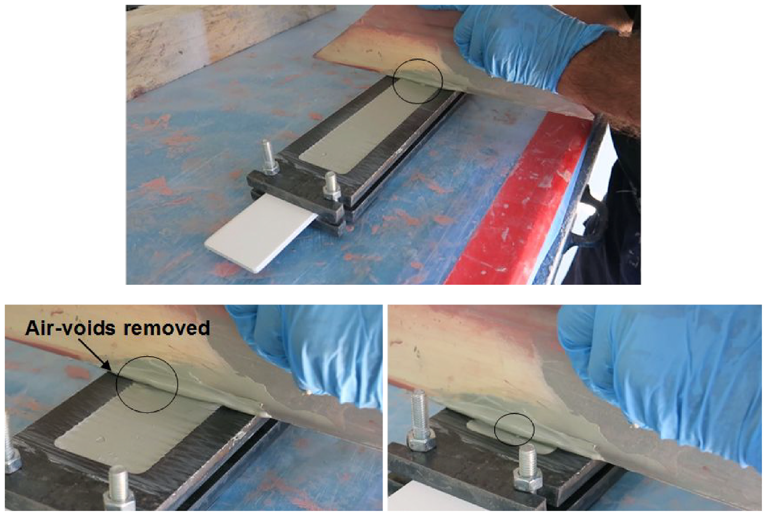
New composite application technique for extraction of air voids in the specially made moulds in stages.
The entrapped air in the polymer-mix is expelled with the above procedure, by drawing the knife palette from one end to the other end of the moulded specimen. The process can be repeated for better results. It is important to expel as much air as possible from the polymeric material, during the casting process to ensure consistency of the results. Both the lay-up specimen production and the new application technique add to the novelty of this work.
The air extraction technique is also demonstrated on large panels (Figure 6). Repetition of the technique using a longboard caused air extraction from the applied mixture by compressing the material while drawing from one end of the panel to the other. Note that the technique derived through this study might be useful for other materials of thixotropic nature which have similar material properties and might influence future studies as an improving application technique to eliminate the voids from mixture during application.
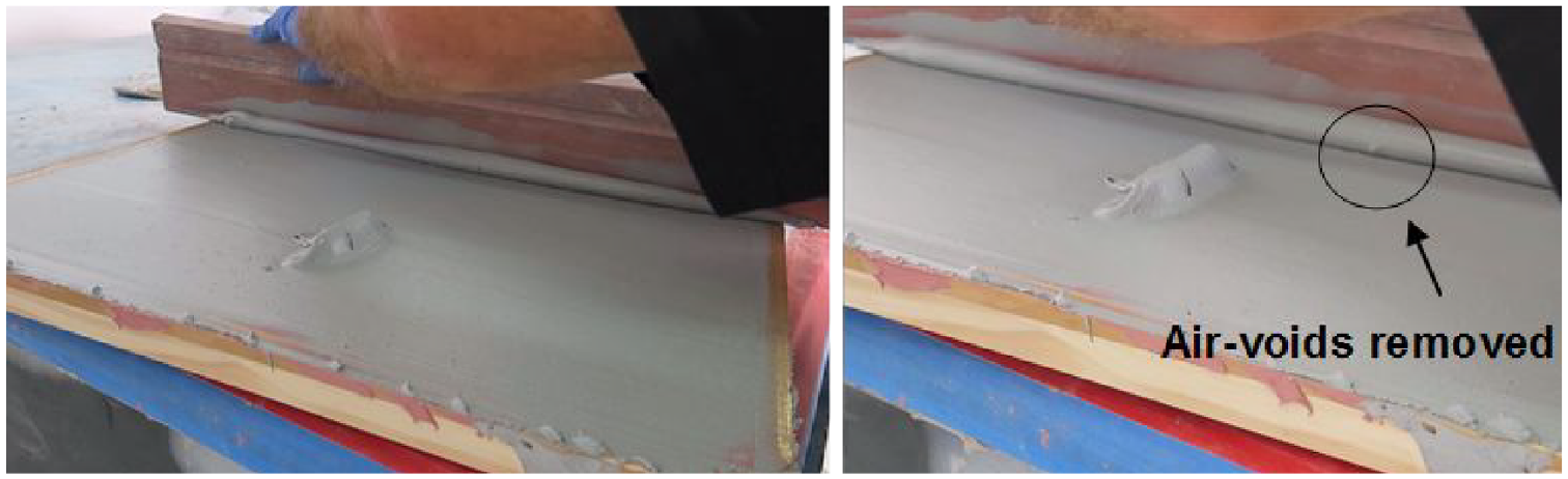
Demonstration of new application technique on a large area – removal of air from the mixture.
Results and discussion
General overview
As mentioned before, the primary purpose of the tests subjected to monotonic load was to fully understand the interaction of the two materials and the response of the bi-material component under bending loads. Moreover, differences between materials with different mechanical properties are of interest. The experimental results generated new knowledge about the failures of thick polymeric coating components applied on vessels and the basis for the development of new material design guidelines. New standard test methods for hybrid beams and general testing of coating systems arise from this study. Also, new on-site mixing guidelines and improved application techniques which minimise entrapped air are proposed.
Some of the examined parameters such as the thickness of the polymer, maximum load and deformation capabilities, the maximum strength and strains are discussed. Mechanical characteristics obtained from other experiments of the bulk materials are also listed in section 3.3 ‘Materials and substrate preparation’. The mechanical characteristics of the materials were established by the authors and were not previously available in the literature.
The four-point bend test configuration permitted examination of the hybrid metal-to-polymer composite structure under pure bending. The outer surface of the polymer is subjected to tensile loads enabling investigation of the fracture (cohesive) behaviour of the polymer. As mentioned before, due to the asymmetry of the specimen, the shift of the neutral axis of the structure was specified for each case, by taking into account the mechanical properties and the geometry of the polymer’s cross section. Due to the low stiffness of all polymeric materials, the shift of the neutral axis is minimal for all six cases.
Stress-strain response of four-point bending tested configurations
The longitudinal stress-strain responses of the three composite materials are shown in Figure 7. A predominantly linear response was observed in materials A and B different under pure bending load. Material C also exhibited linear response initially, followed by a nonlinear response from 0.6% strain onwards. A plateau was formed after 15 MPa, showing a pseudo-ductile response. The effect and estimation of the pseudo-ductility will be discussed in the next section. In general, the composite materials fractured once they have reached their maximum strength and strains. An abrupt reduction in force can be seen after composite fracture, and the steel continued to take the load. It is evident that the strongest material (material A) presented the most substantial relative decrease in strength compared to the other two composites with lower composite strengths (Figure 7). The tests were stopped after composite failure, as any results after polymer fracture would be meaningless for this study.
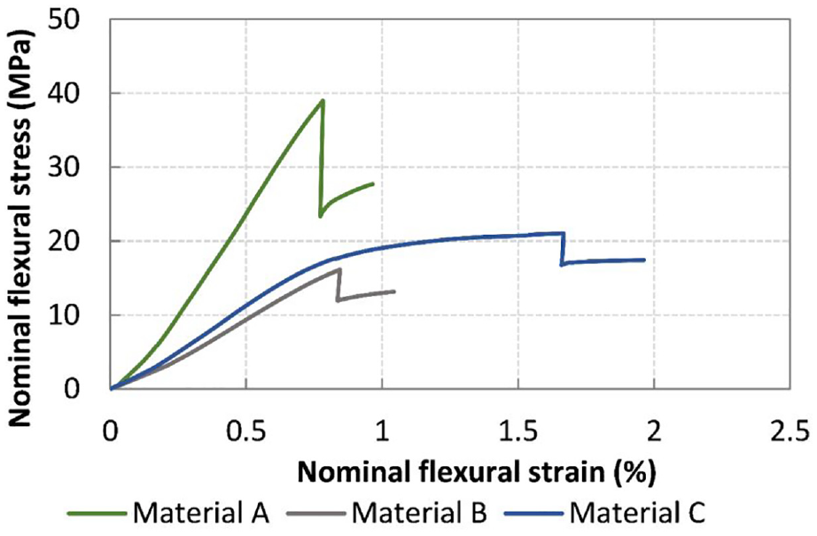
Stress-strain curves of the hybrid composite beam undergoing flexural load.
Dissimilarities were observed in stiffness, strength and strains to failure, between the materials. The linearity of the stress-strain curve (materials A and B) could be attributed to the coupling of the polymer with the steel backing plate. The constitutive stress-strain response of the bulk materials has also shown an initially linear behaviour under flexural load. The (pseudo-ductile) nonlinear behaviour of material C (Figure 7), was also observed in the bulk material testing.
The monotonic response of structures or components is primarily performed to obtain the strength and stiffness characteristics in structural design, and the influence of deformation capabilities of the components is many times ignored. In the case of a bi-material component, the ability of the deformation of the polymeric material component and the load transfer is of paramount importance. The strain transfer is continuous through the hybrid structure component, thus allowing us to understand the likelihood of failure in the composite layer.
The strain transfer between the two (interacting) materials is continuous through the depth of the component. The composites failed when their failure strain capabilities were reached under monotonic load. For reference, strains to failure of the bulk materials can be found in Tables 1 and 2 presented previously. An interesting fact is the slight reduction of failure strains in the thicker geometries of materials B and C (Figure 8).
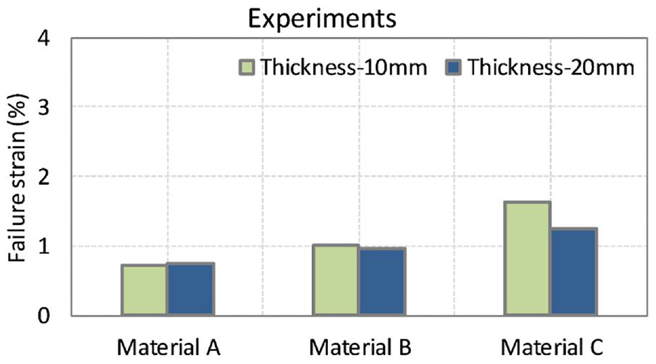
Experimental results showing comparison of elongation at break between the three examined materials and the effect of thickness.
Another significant finding of this study is that the composite fails at strains which exceed the linear elastic strains of the steel backing panel. The yield strain of steel is around 0.1% whereas the polymer-composites have strains values ranging from 0.8% to 1.65% (or even 2% in some cases) when tested in the opening mode of failure (Figure 8). The composite is not designed to sustain as high stresses as the design stresses of steel, because of its low modulus. However, the deformation allowance of the composite material is high. The deflections that can be sustained by the composite material are greater than the linear elastic strains of the steel substrate. The deflections sustained by the steel substrate are transmitted to the composite by the strain transfer mechanism.
In general, there are not many striking differences in the failure strains and strengths of the composites in the thin (10 mm) and thick (20 mm) geometries. As expected, failure occurred when the failure strains and stresses of the material are reached, for both geometries (Figures 8 and 9).
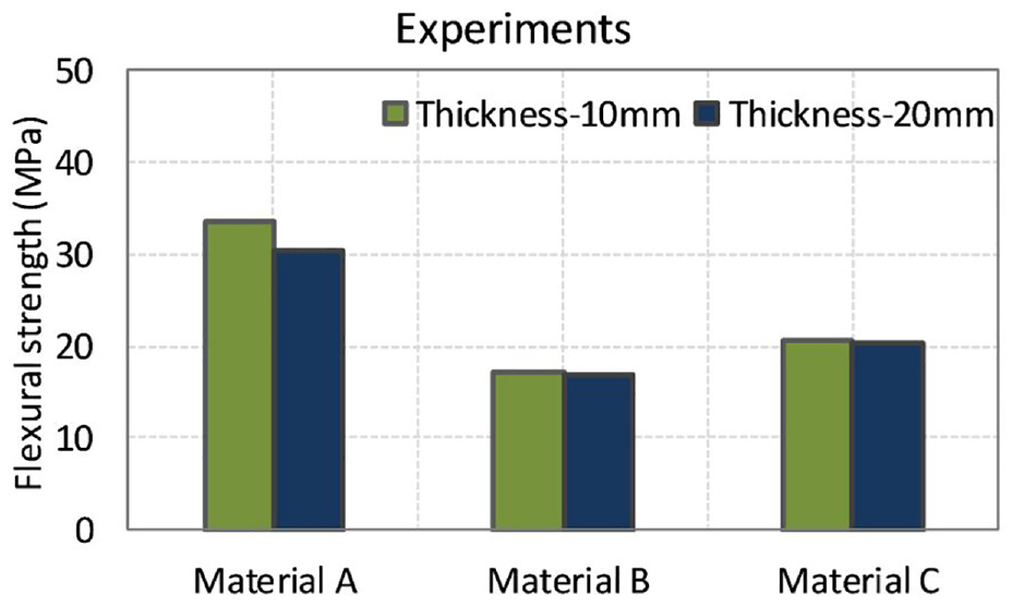
Experimental results showing the flexural strength of examined materials and thickness effect.
Failure loads and deformation of material cases
The load-deformation curves of material’s A cases are shown in Figure 10. The stiffening effect of thicker specimens is noticed from Figure 10. Further discussion on the stiffness of all polymers follows in a subsequent section. Although the components examined are of different cross-section geometry, the results show that specimens with a composite depth of 20 mm reach the material’s maximum strength at lower applied displacements compared to samples of half thickness.
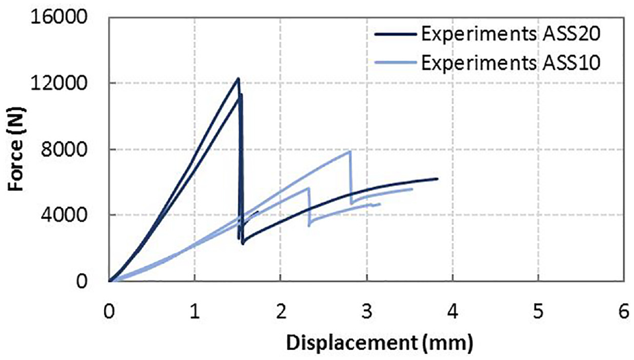
Two experimental results presented of each thickness, showing the load-deformation response of material A, composite thicknesses of 10 and 20 mm.
As discussed previously, the stress distribution is discontinuous through the depth of the component but linear and continuous through the thickness of each of the materials. Similar strength values are observed between the thin and thick polymer-composite components. Nevertheless, the bending capacity of the specimen with the 20 mm thick polymer is higher than the 10 mm thin polymer component (Figure 11).
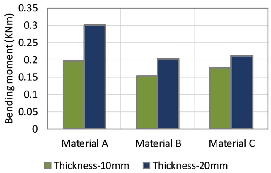
Experimental results showing the flexural capacity of examined materials and thickness effect.
Thicker (20 mm composite) specimens, for example, presented greater ability to sustain the flexural load. However, the thicker the composite layers, the stiffer it becomes under flexural load, which has a detrimental effect on its ability to deform under flexural loads. The flexural capacity of polymer-composites increases with the increase in thickness (Figures 11 and 12). This outcome was observed in all materials examined.
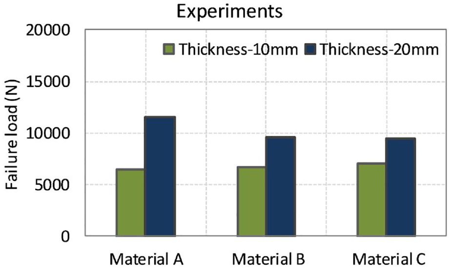
Experimental results showing the comparison of composite failure loads for different materials and geometries.
In addition to this, the application of the composite in thick layers contributes to the shift of the neutral axis from the centroid of the metal structure itself. The distance between the free surface of the polymer and the neutral surface increases as the composite thickness is increased. This, in turn, imposes a higher load on the outer surface of the material, leading to a premature failure of the composite.
The experimental results indicated a strong influence between the deflection capabilities and the thickness of the applied composite. The thicker geometry (composite applied in 20 mm thickness), reduced the deformation sustained by the composite by 42%, 36% and just below 49% for materials A, B and C respectively (Figure 13). The impact of the increased thickness will also be discussed in the fatigue chapter to determine any influence on the fatigue life of the component.
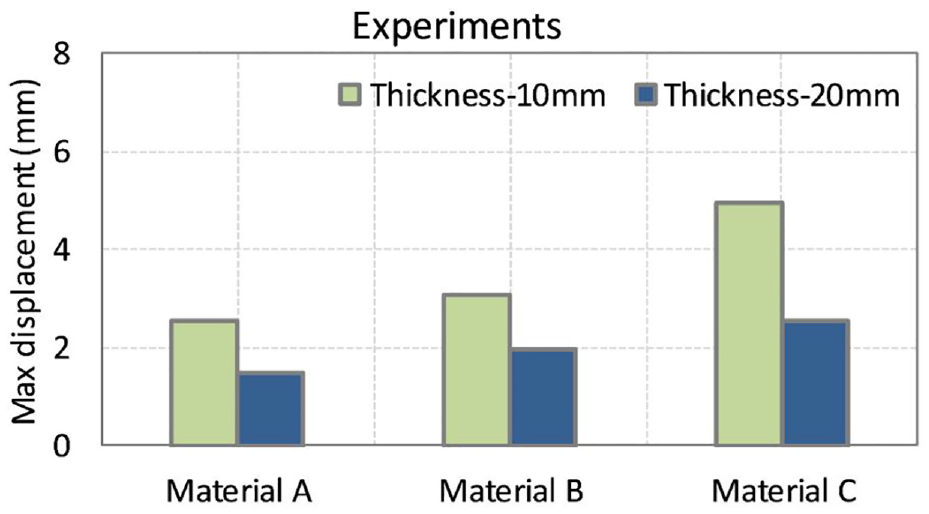
Experimental results showing the comparison of maximum deflection for different materials and geometries.
Concept of pseudo-ductility
The flexural tests have shown a predominantly linear response for two of the materials (materials A and B). Nonetheless, material C presented a nonlinear response. A nonlinear elastic behaviour is favoured in the sense that redistribution of the fibres in the composite will be allowed. This phenomenon is described as ‘pseudo-ductility’. In this case, the concept of ‘pseudo-ductility’ refers to the geometric effect of fibre-particles reorientation as well as yielding of the matrix. For clarity the pseudo-ductile strain

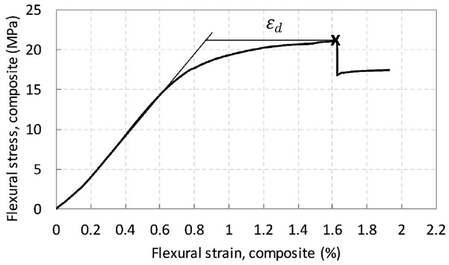
A graphical explanation of the method used to determine the yield stress and pseudo-ductile strain.
Flexural rigidity of the member
As can be seen from Figure 10, the material with the most substantial stiffness is material A, which also has the higher strength of the examined materials. The bending stiffness was calculated with equation (3.1). It is evident from Figure 15 that any increase in thickness causes an increase in bending stiffness. A remarkable observation is that the flexural rigidity of material A is increased by a factor of three when the composite thickness is doubled from 10 to 20 mm. This increase in flexural rigidity with increase in thickness might affect the performance of the material especially its fatigue performance during loading and unloading. The material becomes significantly stiffer when its thickness is doubled which for this maritime application might affect its performance under fatigue. This is more evident with the flexural rigidity increased by nearly a factor of 4 in material A. Material A is also the material with the highest strength and stiffness compared to all three polymer-composites studied. On the other hand, the member with composite B has the lowest flexural rigidity of all members. The increase in thickness has a more considerable effect on the bending stiffness of the beam with composite C than in B, with factors 2.5 and 2.15 correspondingly.

Where:
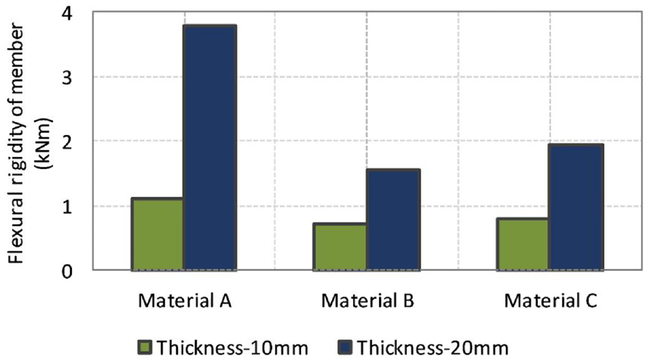
Experimental results showing the comparison of the flexural rigidity between the thinly and thickly coated member.
Fracture and failure modes in quasi-static tests
Fracture mechanism
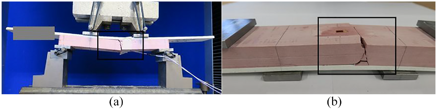
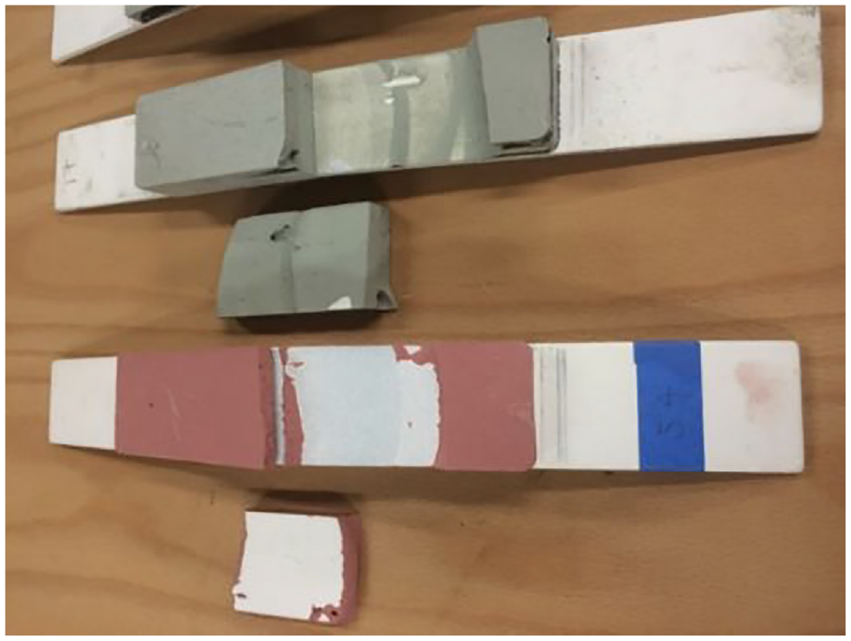
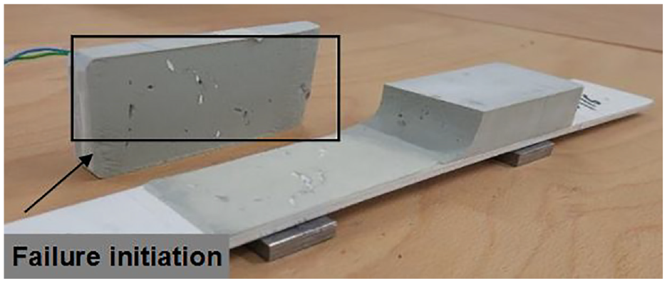
In general, all specimens present the same mode of failure under quasi-static loading. Brittle failure of the composite is observed at fracture. The crack formation is rapid, and there is a release of energy upon fracture, with pieces falling from the material (Figure 16). After vertical cohesive failure, the crack propagates along the interface of the bonded materials. The vertical and horizontal types of failure are encountered in real yacht applications. However, in real yacht failures, the formed cracks are finer than those obtained from quasi-static tests, due to the lower magnitude repeated loadings encountered in service.
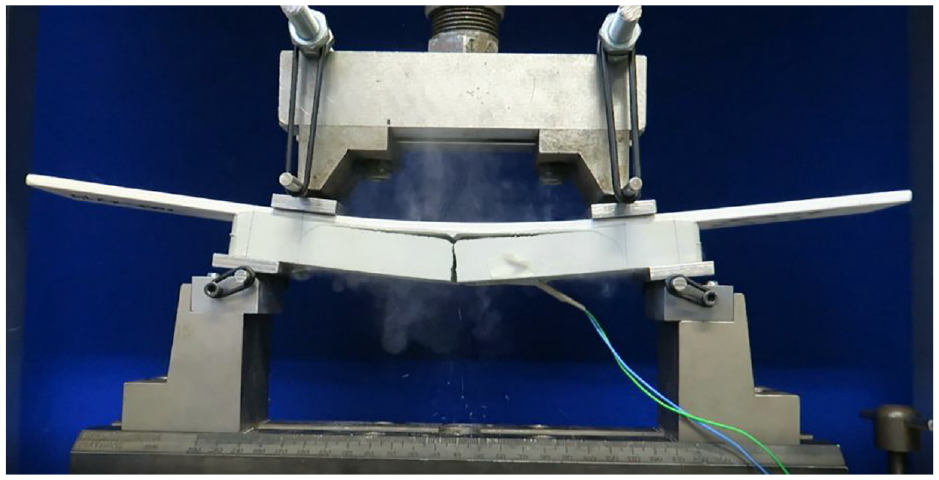
Rupture in a thick cross-section geometry, scheme CSS20 (note the larger load span in this case than the remaining tests, material particles discharge during fracture).
There is no known available literature discussing these types of failures; this is one of the first studies addressing these. Often, the crack propagates towards a defect within the interface of the bonded materials. The types of failures are discussed more extensively in a dedicated section below.
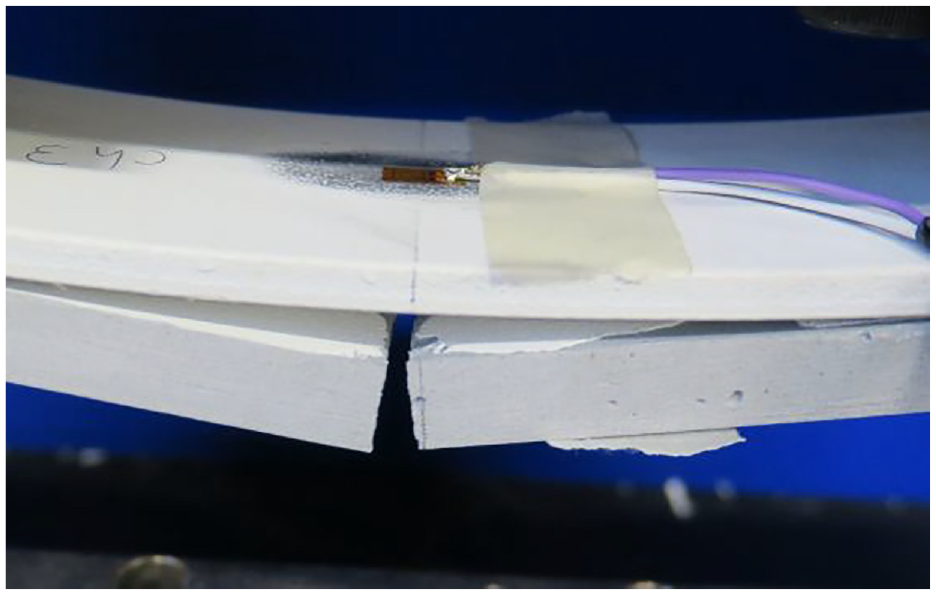
Final fracture of the composite under quasi-static loadings is attributed to 90% crack initiation and 10% due to crack propagation. The crack forms rapidly through the depth of the composite, shown as a split of the two surfaces.
A typical fracture under quasi-static loading is shown in Figure 17. Fracture of the polymer-composite components is sudden, and cracking occurs without any warning. In many cases, the influence of air voids in the applied polymer could cause a dynamic fracture. Air pockets can be added during mixing of the materials and application. Application of the composite in thick layers should be avoided. Minimising the thickness of the composite applied will reduce the size of voids added to the mixture. The influence of voids on the static response of the material is examined in a subsequent section.
Macrostructure fracture of composite B under quasi-static loading, (a) side view (b) top view.
Principal mode of failure
All three different materials and different geometries (thickness-based) fractured under bending (no delamination was seen before the vertical cohesive fracture of the composite). The first mode of failure seen in all cases and materials tested is the cohesive fracture (vertical) of the composite. The second mode of failure is defined as the shear crack propagation along the length of the coating (Figure 19). The Figures 18 and 19 below present typical fractures of composites A, B and C under monotonic loading.
(a and b) Typical static fracture, scheme ASS20.
Composite cohesive fracture and adhesive failure under static load, scheme BSS10.
The static tests showed crack propagation along the interface of primer/composite after the fracture of the composite. This indicated the response of the material in a real application under quasi-static load. Examination of the interaction of the metal-composite test components is essential to the development of design guidelines for future materials.
Secondary mode of failure
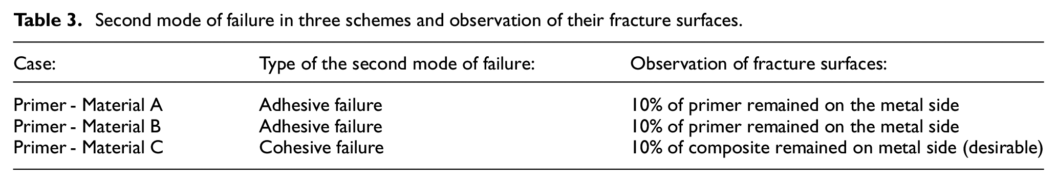
There are two ways a metal-primer-composite scheme may fail after crack initiation, as listed below:
Cohesive failure of composite outside the bonded area: desirable outcome as it limits corrosion of the metal substrate, and the scheme has achieved maximum possible performance.
Adhesive failure by fracture of the primer layer when the strength of the primer bond is exceeded.
Adhesive failures are characterised by the absence of (most of) the primer (adhesive layer) on one of the bonding surfaces. Failure occurs along the interface between the adhesive layer and the adherents (metal/composite in this case). Cohesive failures are characterised by the apparent presence of adhesive material on the matching faces of both adherents (metal/composite). Table 3 summarises the types of failures and observation of their fracture surfaces. Two types of (secondary) failure were understood; adhesive failure of the system (schemes A and B) and cohesive failure within the composite (scheme C). The adhesive and cohesive failures are shown in Figure 20.
Second mode of failure in three schemes and observation of their fracture surfaces.
Observation of second mode failures in material schemes C and A - Cohesive failure within the composite (top), adhesive failure in primer (bottom).
Cohesive versus adhesive failure
The substrate materials can inhibit a rigidity higher than that of the coating (composite). Under such conditions, the fracture will occur within the coating if the system experiences an external force of sufficient intensity. 9 Cohesive failure will result if the adhesion at the interface exceeds the cohesion of the composite layer. Otherwise, adhesive failure is the result, indicating a separation between the coating and substrate.
Cohesive failure indicates the attainment of optimal adhesion strength. Components A and B, failed adhesively because the adhesion strength (primer-composite) was lower than the composite strength. Both types of failure are encountered in practice, but cohesive failure is preferable in yacht applications to protect against corrosion. The corrosion of the metal substrate material will be limited if a cohesive failure occurs. However, an adhesive failure removes the primer layer which could have an impact of corrosion of the substrate material.
Effect of voids/defects in the composite material
The fracture of the polymer-composite components is sudden and fracture occurs without any warning. A brittle failure mode is seen under quasi-static flexural load. In many cases, air voids are incorporated in the composite during the mixing process and application of the material.
Air pockets in the composite could reduce the performance of the material. Failures within the composite often cause a cohesive fracture in the composite before its full capacity is reached. Premature failures are also often encountered in the form of delamination (depending on the location of the voids).
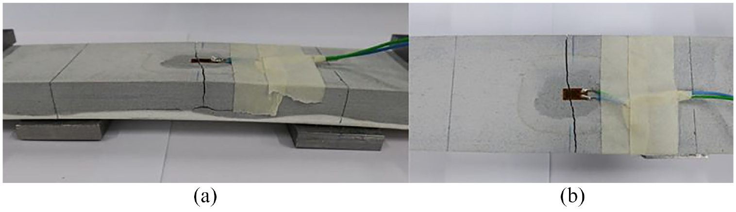
Figures 21 and 22 illustrate two examples of delamination failures due to the void presence at the interface of the material with the underlying primer layer. The test setup of this section is slightly different from the remaining tests; the specimen is supported on the steel plate, and the load span is larger than in the general tests outlined above. Supporting the specimen on the steel rather than the composite (Figure 23) causes a small increase of shear stress locally near the lower roller supports but is not enough to cause delamination rather than cohesive (vertical) fracture of the composite.
Premature delamination failure due to void presence at the interface with primer layer – SS20, specimen 1.
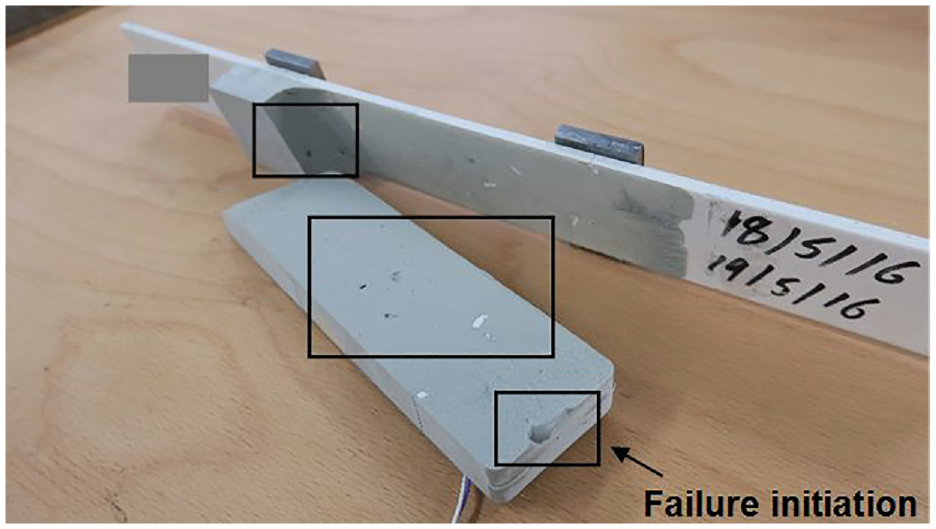
Premature delamination failure due to void presence at the interface with primer layer – SS20, specimen 2.
Four-point bend test setup, lower supports on steel (lower span length = 230 mm, upper span length = 150 mm).
The interaction of the defects near the substrate material has caused a premature failure of the specimens. Delamination initiated from the edge of the specimens and rapidly propagated through the interface. As a result, the composite was detached from the substrate in both specimen cases (Figures 21 and 22). The measured results from Figure 24 support that premature failure was caused by the presence of voids.
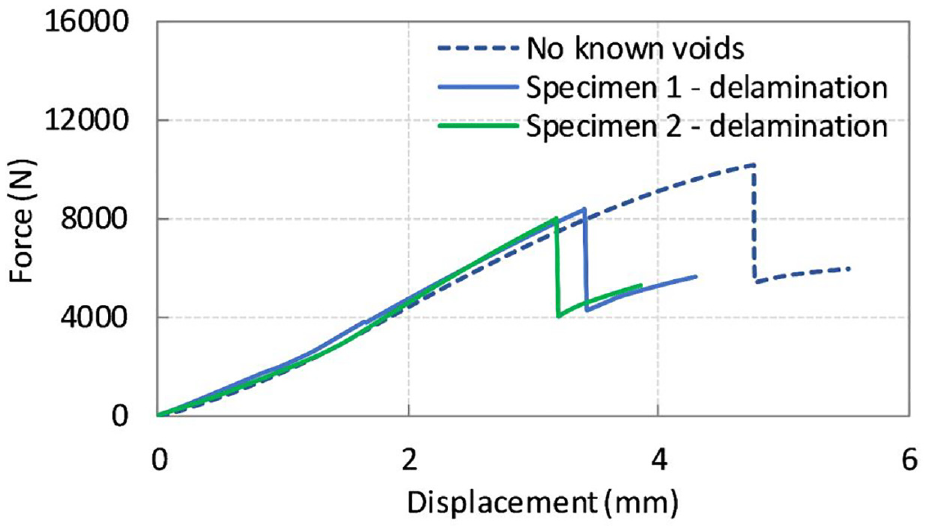
Force-displacement graph showing the influence of voids along the composite–primer interface.
Delamination failure occurred as a ‘dynamic fracture’. The amount of energy released during fracture resulted in a loud fracture and detachment of the composite from the substrate. The interaction of considerably small voids (less than 1mm diameter) formed at the primer – composite interface can reduce the performance of the material. The detachment of the composite was sudden and relatively quick. Voids in the primer-composite interface could be reduced by initially applying a thin layer (1 mm) of composite onto the primer surface.
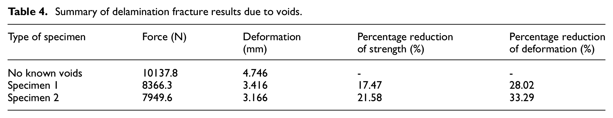
The reduction in strength for specimens 1 and 2 was about 17.5% and just above 21% accordingly. Also, the reduction in the maximum deformation at failure was about 28% and 33% (Table 4). It is thus evident from experimental findings that voids have a detrimental effect on the performance of the composite. Premature failures could be avoided by minimising the size and the intensity of the voids/defects in the composite material. This section covered the influence of voids on the quasi-static response of the composites. The effect of voids in the composite fatigue life will be discussed in a different paper.
Summary of delamination fracture results due to voids.
It is worth noted that the quantification of the voids is mainly done by visual means after the fracture has occurred. This method is deemed as most accurate as visual means can clearly show reasonable sized voids and no additional method is required for this investigation.
Conclusions
The following conclusions can be drawn from the present study. The flexural behaviour of coated test samples was measured experimentally under pure bending load. The flexural stress-strain characteristics of the hybrid steel-to-composite component were established.
An experimental procedure for investigating the failure modes and the mechanical properties of thick polymer-composite application to metallic substrates was presented for the first time. Analytical and experimental methods enabled a better understanding of the problem. The fundamental mechanical properties of the polymer-composite materials and the impact of voids/imperfections in the materials provided insight into the design criteria of the composite materials and the requirements of the entire substrate-to-composite coating system.
A two-step procedure, involving analytical and experimental methods investigating the mechanical response of composite polymers applied on hull and superstructure substrates was presented for the first time in this paper.
Polymer-composite material performance is limited by linear elasticity and the sudden brittle failure they often exhibit. It is possible to mitigate this inherent limitation and enlarge the design space of these materials by applying thinner layers of material or by using materials with ‘pseudo-ductile’ behaviour. Brittle failure occurs without any warning, and it is sudden. Linear elastic stress to strain behaviour promotes brittle failure reduces design allowable and precludes the realisation of the materials’ full potential.
Achieving a nonlinear ‘pseudo-ductile’ response with the ability to yield, similarly to metals, is therefore highly desirable. Pseudo-ductile strain design criteria are favourable as they promote better performance of the composite materials.
Also, materials with large strains to failure demonstrated to extend the performance of the bulk material. The increased failure strain allowed more nonlinearity to develop, highlighting the increased potential of its performance.
Good agreement was demonstrated between the failure modes of experimental specimens and the real in-service failure modes seen on yacht structures. Each material showed different primary and secondary mode of failure of the composite, which counterparts the realistic failures. Thus, conclusions of the causes of real failures were possible to be obtained through this research study. Full-scale tests of the actual coated component were performed.
Material C coating configuration provides a combination of low bending stiffness (of 3 kNm) and an increased failure strain of approximately 2% when the thickness of the composite has a thickness of 10 mm. It was observed that in material C, an increase of the thickness of a factor of 2, leads to an increase in bending stiffness by a factor of 2.6. The largest increase in bending stiffness was seen in material A system, where the bending stiffness has increased by a factor of 3. Greater flexibility and better material performance are achieved when the size of the materials is minimised to 10 mm. It is postulated that reducing the thickness of the polymer could suppress cracking and delamination.
Footnotes
Appendix
Acknowledgements
This work was carried out as part of a Knowledge Transfer Partnership programme between Newcastle University and Safinah Ltd. The work was financially supported by Innovate UK and Safinah Ltd. The authors also gratefully acknowledge the financial support and assistance in the specimen production by Lürssen Werft GmbH & Co.KG, Mankiewicz Gebr. & Co. and Pinmar – Global Yachting Group. Special thanks to the engineers and technicians of the laboratories in Stephenson Building at Newcastle University, for helping with the set-up of the experiments.
Declaration of conflicting interests
The author(s) declared no potential conflicts of interest with respect to the research, authorship, and/or publication of this article.
Funding
The author(s) disclosed receipt of the following financial support for the research, authorship, and/or publication of this article: This work was carried out at Newcastle University, Marine Technology, School of Engineering, Newcastle upon Tyne NE1 7RU. Also, this work was supported financially by Innovate UK, Safinah Ltd, Lürssen Werft GmbH & Co.KG, Mankiewicz Gebr. & Co. and Pinmar – Global Yachting Group as part of a KTP project.