The study presents the hydrodynamic performance and wave energy conversion of a hybrid floating breakwater under the framework of small amplitude linear wave theory. The hybrid floating breakwater is composed of a partially liquid-filled rectangular-box type tank with built-in buoys connected to a Power Take-Off (PTO) (linear inductance generator) and is excited under regular wave conditions for (a) constrained roll motion, and (b) constrained surge, heave, and roll motion. The Boundary Element Method (BEM) is employed with the assumption of modest sloshing in the tank of the hybrid floating breakwater to estimate the hydrodynamic efficiency of the hybrid floating breakwater. Further, the experimental investigation on the Wave Energy Converter (WEC) capabilities and the hydrodynamic coefficients (wave reflection and transmission coefficients) are estimated for the excitation frequencies corresponding to nondimensional wavenumber. The present study reveals that the hybrid concept improves wave attenuation performance by 20%–35% compared to conventional floating breakwaters by increasing wave attenuation, damping and stabilizing the wave transmission coefficient within . The experimental investigation shows that hybrid floating breakwater attaints its floating stability for the depth 15 – 25% of partially filled fluid for which the proposed design as floating breakwater as well as WEC system is achieved for a wide range of excitation frequencies. Furthermore, the hybrid floating breakwater functions as a barrier which is noted to be capable of significantly attenuating incoming progressive waves below the predetermined threshold values of wave attenuation characteristics, in addition to converting wave energy.
Ocean waves are frequently referred to as an appealing renewable energy source since they are more persistent and geographically concentrated than other kinds of renewable energy.1 The cost-effectiveness of Wave Energy Converters (WECs) has yet to be established, and energy harvesting from sea waves is still in its infancy, with no WEC having reached the commercial stage. Wave energy’s capital costs presently exceed those of conventional energy generation.2 Several recent studies have emphasized integrating WECs with offshore structures (breakwaters and wind turbines) rather than deploying standalone WEC devices, which also improves their survivability.3–6 Oscillating Water Columns (OWC), Overtopping Wave Energy Devices (OWECs), point absorbers, oscillating wave surge converters, and raft-type devices are among the wave energy conversion technologies that have been created.7. Breakwaters, including fixed and floating, are widely regarded as the finest maritime structures for integrating these WECs. However, combining WEC with a floating breakwater not only has the key benefits of reduced requirements for seabed conditions, lower environmental impact, and the ability to be used onshore, nearshore, and offshore, where fixed breakwaters are limited by depth,8 but also has a high concentration of wave energy closer to the surface, allowing the WEC device to convert wave energy more efficiently.
Floating breakwaters are of a variety of shapes and sizes, including pontoons, slope floats, discarded tires, cylinders, and tethered floats. The floating breakwater can achieve adequate wave reduction or energy attenuation if its width is on the order of half the wavelength and/or if its natural period of oscillation is much longer compared to the wave period.8 Furthermore, the radius of gyration and depth of submergence appear to substantially affect the attenuation characteristics, in addition to mass. Concerning construction simplicity and maintenance requirements, the single rectangular pontoon-type floating breakwater is considered a viable system or a benchmark against which other potential floating breakwater systems can be evaluated. Drimer et al.9 simplified analytical model for a rectangular floating breakwater (FB) in water of finite depth, that can offer adequate protection against waves with wavelengths up to a few times the width of the structure, so long as the clearance is small enough. Lee10 using the application of an analytic solution to the heave radiation problem of a rectangular structure found that an increase in the structure’s width and a decrease in submergence result in a corresponding increase in the generated waves, added mass, and radiation damping coefficients. Conversely, a study conducted by Sannasiraj et al.11 compared the motion response of a solitary floating pontoon for three distinct mooring configurations namely (i) mooring at water level, (ii) mooring at the base bottom, and (iii) cross mooring at the base bottom and discovered that the mooring configurations had minimal impact on the wave transmission. In contrast, it has been noted that dual systems exhibit superior wave attenuation capabilities compared to a solitary floating system. This can be accomplished by augmenting the radius of gyration of the system without concurrently increasing its mass.12–17
Furthermore, several investigations are being conducted on the effect of hydrodynamic performance on various floating-structure shapes. Liang et al.18 compared the spar buoy floating breakwater to the typical pontoon floating breakwater using theoretical and experimental measurements. The floating spar buoy breakwater has been found to be effective at transforming waves and reducing mooring force. Zhang et al.19 use a viscous flow model to study the wave-body interaction on a rectangular and inverted L-type fixed floating breakwater. The L-type floating breakwater, derived from the rectangular and inverted L-type breakwaters, is found to perform efficiently under the same hydrodynamic conditions. According to Nikpour et al.20 on the reducing mooring forces and structural motion, the trapezoidal-shaped floating breakwater with a side slope performed better than the rectangular floating breakwater in wave transformation. Deng et al.21 conducted a hydrodynamic evaluation of a T-shaped floating breakwater using the semi-analytical matched eigenfunction expansion method (EFEM) and concluded that wave attenuation capability can be achieved over a wide range of wave frequencies when the screen is deployed near the ends. Furthermore, multiple cost-effective floating breakwaters with varying relative width and draft requirements have been introduced.22–25). Patil and Karmakar26 used a submerged rubble mound breakwater and a rectangular and circular submerged floating tunnel (SFT) to show that coupled structures are more effective at mitigating waves than a single floating structure. When the findings of the literature are summarized, it is discovered that the floating breakwater can be efficiently used as a wave-attenuating structure by coupling with a reef structure, using multiple systems, or obtaining external damping help to limit structural motion. As a result, integrating a wave energy converter (WEC) with the floating breakwater could potentially increase both the absorption of wave energy and the breakwater’s attenuation properties.
Significant studies has been carried out to evaluate the power efficiency of WECs that could be coupled with other coastal structures.27 Because of its effective wave attenuation performance, pile-restrained box-type floating breakwaters (PRFB) are often used.28–32 Ning et al.33 investigated the hydrodynamic performance of a floating breakwater with power take-off (PTO) devices confined by vertical piles. Zhao and Ning34 and Zhao et al.35 designed a novel system with a front oscillating buoy type WEC and a rear fixed pontoon to improve the energy conversion efficiency of single pontoon breakwater-type WEC systems. Zhao et al.36, Zhao et al.35, and Zhang et al.6 investigated the WEC that is installed on the weather side of a fixed or floating breakwater to improve energy generation efficiency. McIver and Evans37 and Zhao et al.38 research, on the other hand, have focused boosting wave energy density by restricting wave energy to a specified zone, either by putting the WEC device in front of a sea wall or by considering the dual floating system. The study found that the superposition of incident and reflected waves on the weather side of the breakwater or seawall improved WEC efficiency significantly, and a hybrid system formed by combining a WEC and a floating breakwater serves two purposes: coastal defense and wave energy conversion.
In recent decade, there have been improvements in the energy efficiency of hybrid devices, but there are still significant challenges that must be overcome before they can be commercialized. These difficulties include the operation of a WEC device’s moving parts in harsh maritime environments, as well as durability, maintenance, and lifetime. As a result, fully enclosed WEC devices have evolved in recent years to address the aforementioned issues. Crowley et al.39 presented a WEC architecture for a horizontal circular cylinder with an annular fluid reservoir. The study explored the liquid sloshing inside the tank, which might be caused by the pitching motion of the cylinder on the waves. In the hybrid breakwater system study, the WEC is dependent on the motions of the floating breakwater in reaction to ocean waves, making the floating breakwater less effective. This could be due to the fact that, an oscillating breakwater acts as a wave source, sending waves into the protected water region. Tom et al.40 performed similar investigation by examining the Berkeley Wedge confined to significant heave motion but avoiding severe wave transmissions. Zhang et al.41 recently presented a wave energy converter combined with offshore floating constructions. The two built-in buoys at the tank’s extreme ends are limited to heave motion, which converts sloshing dynamics into mechanical energy, which is subsequently absorbed by the PTO coupled to the buoys to generate power. The research findings prompted a numerical and experimental inquiry into the unique way of gathering ocean wave energy without jeopardizing the hybrid system’s effectiveness as a breakwater. The current study looks at the hydrodynamic performance and WEC efficiency of a two-dimensional rectangular partially liquid-filled tank with built-in buoys connected to a PTO (linear inductance generator) for two different cases: (a) constrained roll motion and (b) constrained surge, heave, and roll motion under regular wave conditions. The study is carried out to optimize the wave attenuation properties of the system to be utilized as a breakwater in hostile maritime settings, in addition to improving the efficiency with which wave energy is collected.
Mathematical formulation
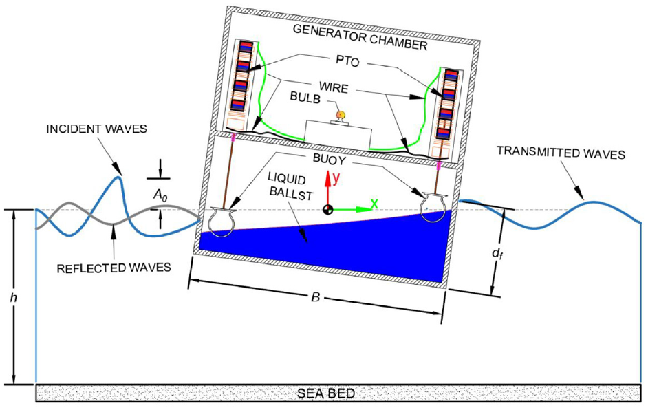
The two-dimensional model for the proposed hybrid floating breakwater using cartesian coordinate system is illustrated in Figure 1. Considering the draft and width , the hybrid floating breakwater is symmetrical around , with the -axis pointing upward from the origin at the still water level. The hybrid floating breakwater is exposed to a train of regular waves with small wave amplitude and angular frequency that propagate in the positive -direction. The velocity potential of the form exists, and the fluid is considered inviscid, incompressible, and the accompanying motion is irrotational satisfying Laplace’s equation given by
where is the circular frequency, is the wave period, is the time in seconds, is a unit imaginary number , and Re is the real component of the spatial complex potential.
Schematic representation of a two-dimensional hybrid floating breakwater.
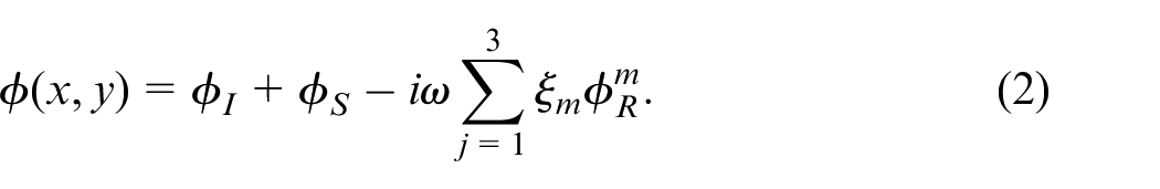
The total velocity potential is obtained by adding the complex amplitudes of the incident potential , scattered potential , radiated potential associated with radiation problem and denotes the complex amplitude of mode of motion ( for surge, for heave, and for roll) defined as
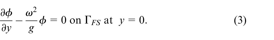
The boundary condition at the mean free surface of the fluid is given by
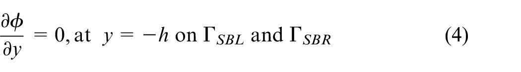
Assuming the finite water of depth , the impervious sea-bed boundary condition is given by
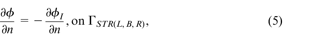
On the surface of the hybrid floating breakwater the boundary conditions for scattering problem are considered as
where, denotes the left structural boundary of hybrid breakwater, denotes the bottom structural boundary of hybrid breakwater, and denotes the right structural boundary of hybrid breakwater.
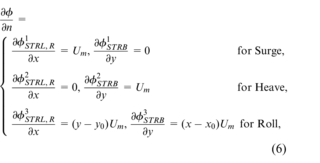
Further, the boundary condition for radiation problem is considered as
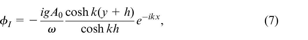
where the unit normal vector pointing outward is denoted as , is the normal velocity of the radiating structure, (, ) are the coordinates of rotation center, and is the incident wave potential given by
and is the wave number which is determined using the dispersion relationship given by
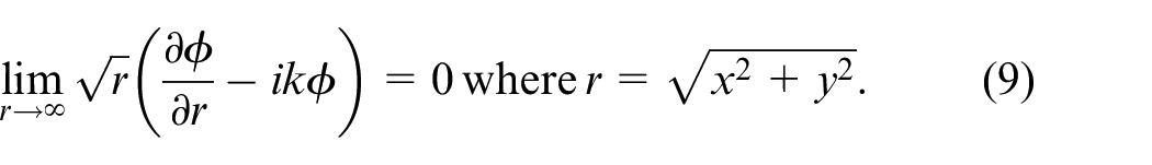
The far field radiation condition is given by
Numerical solution using boundary element method (BEM)
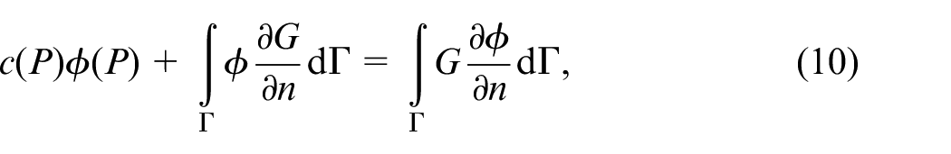
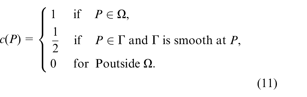
In order to solve the boundary value problem, the boundary element approach is employed with the assumption of modest sloshing in a two-dimensional tank of the hybrid floating breakwater, based on the linear potential wave theory. The fundamental solution and Green’s second identity form the basis of the boundary element method. Laplace’s equation as in equation (1) uses the weighted residue, and Green-Gauss theorem is employed to obtain the solution for the boundary value problem across the boundaries constrained in the fluid domain shown in Figure 2. In generalized form, the boundary integral equation corresponding to equation (1) is given by
where is the free-space Green’s function and is the radial distance between the source point and the field point calculated as . The free term coefficient is given by
Boundary discretization of hybrid breakwater into N constant boundary element.
The boundary integral equation is obtained by applying integral equation (10) over the fluid domain confined to the boundaries .
Domain discretization
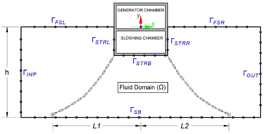
The boundary integral, as described in equation (12), is solved by dividing the domain into constant elements. These elements are numbered in an anticlockwise sequence and are defined for the element by integrating the functions and at the nodal points on the boundary . The value of is chosen to be sufficiently large to ensure convergence of the results in terms of unknown potentials. By taking into account the influential factors and , and applying the specified boundary conditions as described in equations (3)–(9) to the integral equation (12), the boundary value problem for both scattered and radiation problems is solved separately in order to determine the unknowns using the Gauss elimination technique.
Scattering of gravity waves by fixed floating structure
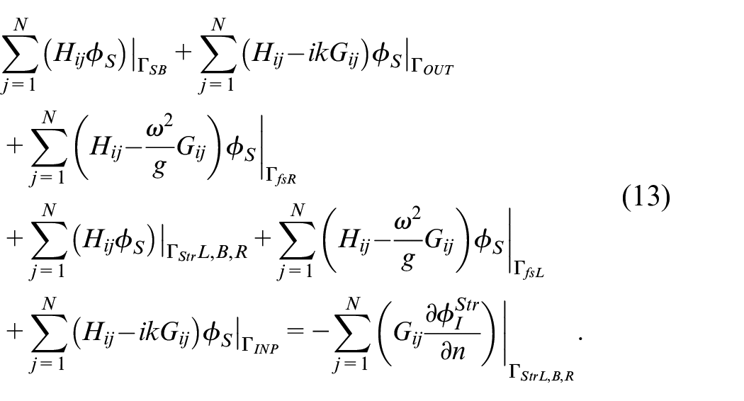
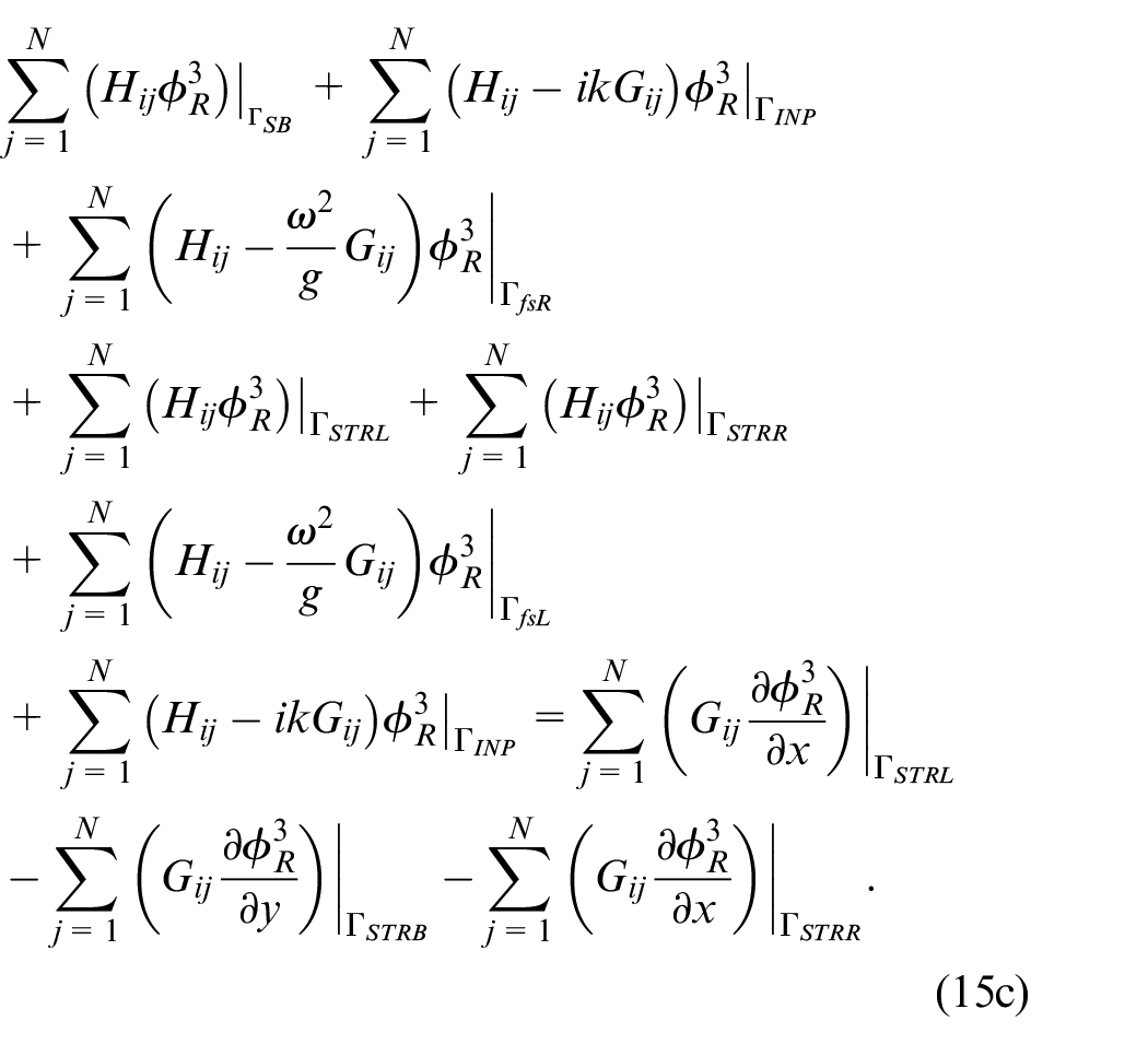
Assuming that the hybrid floating breakwater remains stationary in the scattering problem, the boundary condition equation (5) is applicable at its surface, resulting in zero radiation potential . Therefore, the velocity potential , whereas denotes the unknown scattering potential and represents the known incident potential as specified in equation (7). The discretized equation for the scattering problem, considering the boundary conditions specified in equations (3)–(9) are applied, can be stated as follows:
On solving equation (13), the velocity potentials that are unknown at the mid-nodes of the discretized boundary element are obtained and then used to calculate other engineering parameters of significance, including the wave reflection coefficient, wave-induced forces on the fixed floating breakwater, and the elevation of the free surface waves.
Radiation of gravity waves due to hybrid floating breakwater
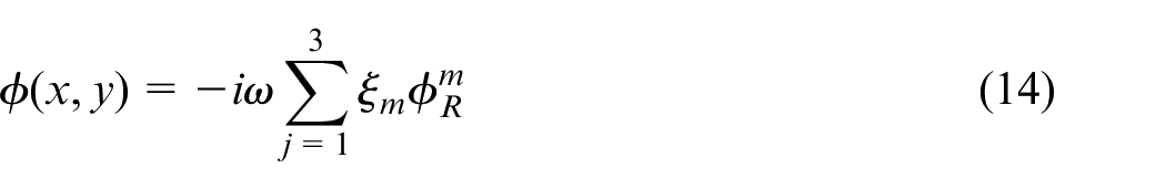
As stated in equation (6), the floating body is subjected to a unit normal velocity in the surge, heave, and roll degrees of freedom in the radiation problems. It is expected that, in the absence of an incoming wave and scattering, the water will exhibit small oscillations. As a result, the radiation problem’s total velocity potential reduces to
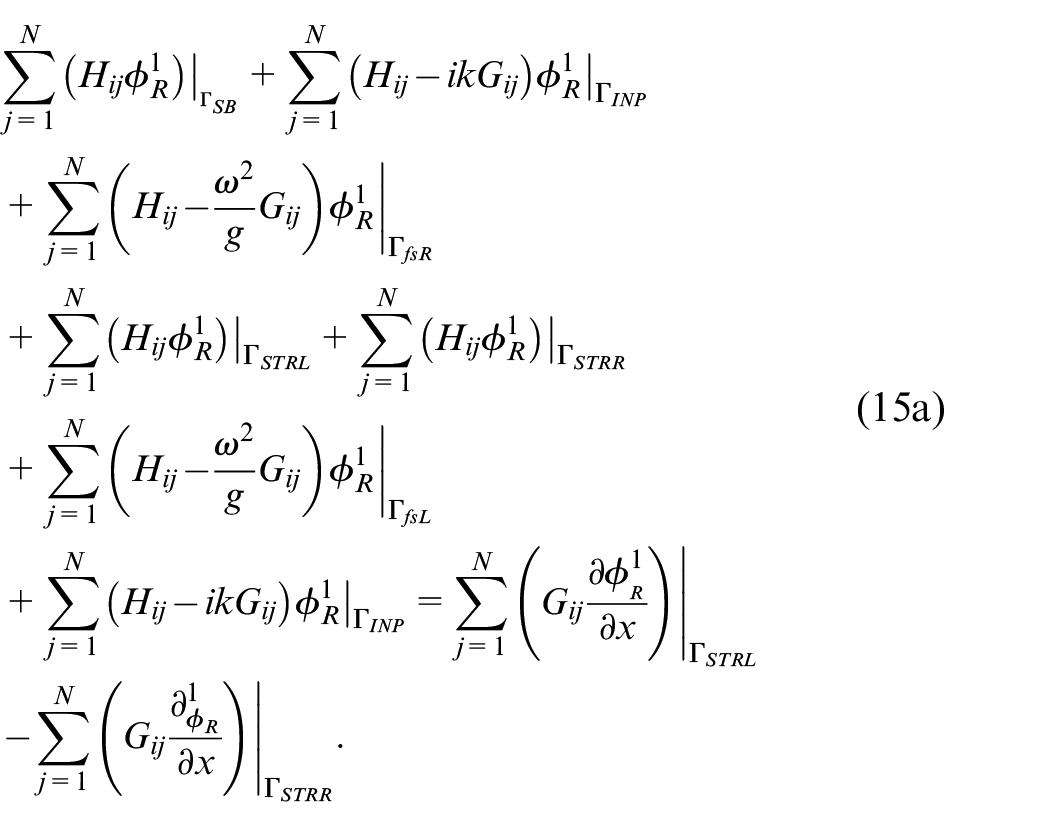
On applying the boundary conditions as stated in equations (3)–(9) to the integral equation (12), the discretized equations for the radiation problem in surge motion is given by
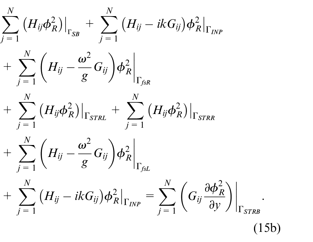
The discretized equations for the radiation problem in the heave motion is given by
Further, the discretized equations for the radiation problem in the roll motion is given by
Wave induced forces and free surface elevation
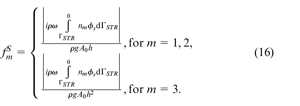
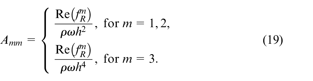
The non-dimensional expression for the frequency-dependent wave excitation forces acting on the hybrid floating breakwater is
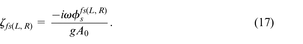
where corresponds to and . is density of sea water and is the unit amplitude of motion of hybrid floating breakwater. In the open water region, the non-dimensional free-surface wave elevation is given by
Radiation forces and hydrodynamic coefficients
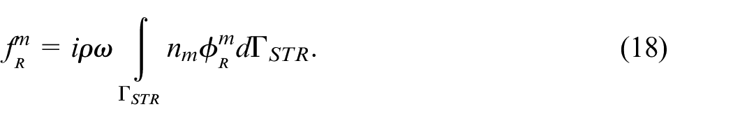
The unknown radiation potential are obtained on solving equations (14)–(16). Further on integrating the pressure over the structural body on wetted borders yields the hydrodynamic radiation force owing to motion of the body of unit amplitude .
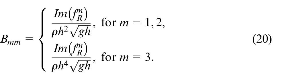
The added mass and radiation damping coefficient are deduced by separating the real and imaginary parts of radiation forces of hybrid floating breakwater. The non-dimensional form of added mass and radiation damping coefficients are computed using the relation given by
Equation of motion
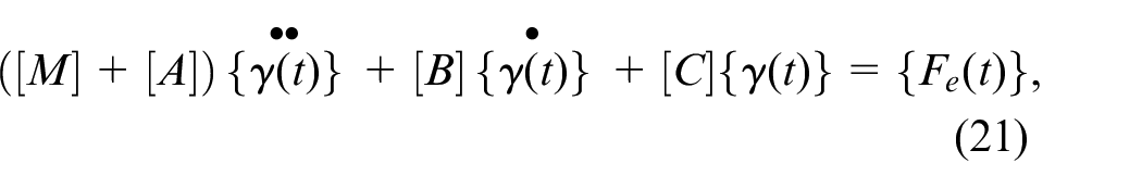
In the equation of motion, the distinct scattering and radiation problems are coupled to determine the dynamic reactions of a hybrid floating breakwater given as
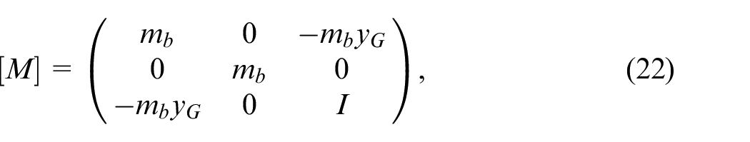
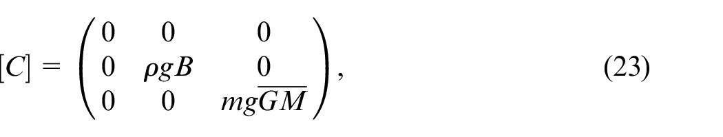
where is the wave excitation force, and are the added mass and radiation damping matrix obtained from equations (19) and (20). The mass matrix of the structure and the hydrodynamic restoring force matrix is given by
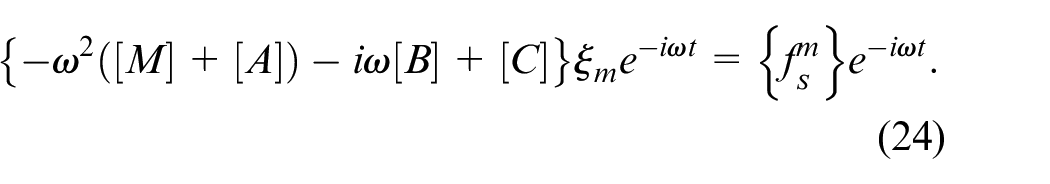
where is the mass per unit length of a hybrid floating breakwater, is the coordinate of the center of gravity, is the mass moment of inertia about water plane and is the metacentric height. Further, by replacing the assumed heave displacement function , velocity , and acceleration into equation (21) we get
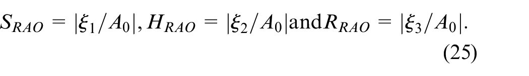
After solving equation (24), the motion responses are obtained, and the Response Amplitude Operators (RAO’s) in surge, heave, and roll are determined as the ratio of motion response to incoming wave amplitude and are expressed as
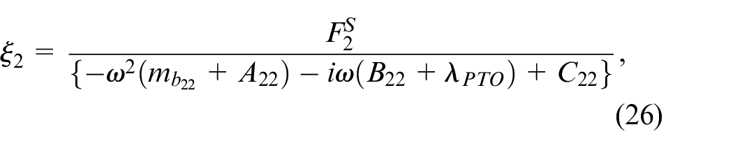
The system is a hybrid floating breakwater when WEC is integrated with a floating breakwater, and a linear PTO damping is utilized to calculate the absorbed power in heave degree of freedom. The amplitude of the heave response for a coupled hybrid floating breakwater with WEC is represented as
where denoted the PTO damping. In the case of a freely heaving structure and for scattering problem considered to be very large so that the resulting heave response amplitude . The ideal PTO damping as described by Zhao et al.36 is represented in the analysis as
The natural frequency of undamped heave is described as
Extraction of wave energy and its efficiency
The capture width ratio (CWR), which has a substantial impact on the hydrodynamic efficiency of a WEC device, is defined as the ratio of the power extracted by the device to the power in the incident wave18 and is given as
where, the incident wave power per unit transverse length is defined as
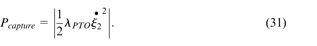
The average power harnessed by the hybrid floating breakwater with power take-off (PTO) damping , as reported in Jeong et al.,42 is expressed as:
Hydrodynamics of hybrid floating breakwater
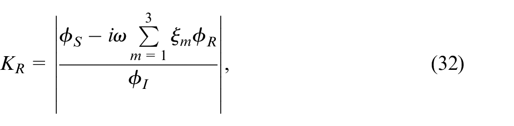
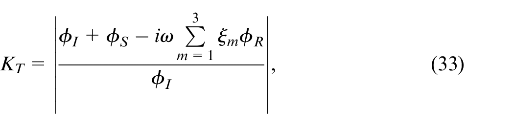
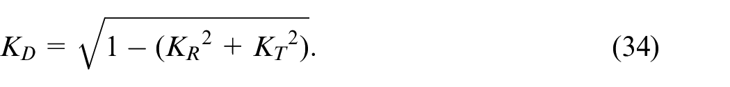
The wave reflection coefficient , energy dissipation coefficient , and wave transmission coefficient of a hybrid floating breakwater as a coastal protection construction are expressed as
Experimental setup and test conditions
The physical model test of a hybrid floating breakwater is performed at Department of Water Resources and Ocean Engineering, National Institute of Technology Karnataka (NITK), Surathkal, India, at a scale of 1:30 in a regular wave flume subjected to varying water depths (45–50 cm), wave heights (6–18 cm), and wave periods (1.6–3.6 s). The experiments are conducted on a hybrid floating breakwater (rectangular partly liquid filled tank with built-in buoys connected to a PTO; linear inductance generator) for two different cases such as (a) confined to only roll motion, and (b) constrained to roll and heave motion.
Dimensional analysis
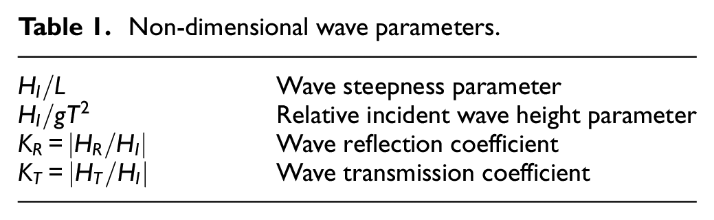
The fundamental quantities and units of measurement for a set of physical quantities is the focus of dimensional analysis. All other measures can be described as the combination of the basis quantities, but none of the base quantities can be stated as a combination of other measurements. With the use of dimensional analysis, the number of determinants in a model of a physical phenomenon may be reduced. Utilizing the dimensional analysis and adopting the Buckingham theorem Fox et al.,43 the dimensionless factors influencing the stability studies of the hybrid floating breakwater are determined (Table 1).
Non-dimensional wave parameters.
Wave steepness parameter
Relative incident wave height parameter
Wave reflection coefficient
Wave transmission coefficient
Model scale
The wave environment off the coast of Mangalore, as well as the ranges of wave heights and wave periods that may be created in the wave flume to fit a sea depth of 0.5 and 0.45 m, are considered while determining the model scale. In the present experimental studies, a geometrically comparable model scale of 1:30 is used to recreate the field circumstances of wave height, wave period, and water depth using Froude’s law.44 The Mangalore coast’s wave height and period range from 1 to 5.4 m and 8 to 12 s, respectively. The regular wave in the range of 0.02–0.24 m with periods 0.8–4 s may be created in the laboratory using the wave flume at NITK, Surathkal Mangalore. In the present study, a Froude’s model scale of 1:30 is adopted.
Methodology of experimental investigation
A series of experiments are conducted to estimate the hydrodynamic characteristics of a hybrid floating breakwater built to be partially filled liquid rectangular-box type floating breakwater with a depth of fill varying between 10% and 30% constrained to have (a) only roll and (b) heave and roll degrees of freedom when subjected to regular waves in a 2D wave flume. The wave flume under consideration has a water depth of 0.5 and 0.45 m, simulating the sea wave conditions off the Indian coast of Mangalore at a model size of 1:30. The system’s draft range for this water depth is restricted to 0–30 cm, which means that the fill depth can only be between 10% and 30%. Second, the system’s draft, which was measured at 30 cm, indicated increased wave reflection for fill depths exceeding 30% and the occurrence of clapotis (the formation of standing waves) over the majority of the wave excitation frequency range. The tank was excited at its natural frequency, causing the partly filled liquid in the sloshing compartment of hybrid floating breakwater to slosh at its resonance. Without considerable dampening, sloshing energy is turned into a long-term linear motion of built-in buoys within the sloshing compartment. The sloshing wave energy is converted into power by driving the buoys using the PTO system placed in the tank to generate the electricity.
Test facilities
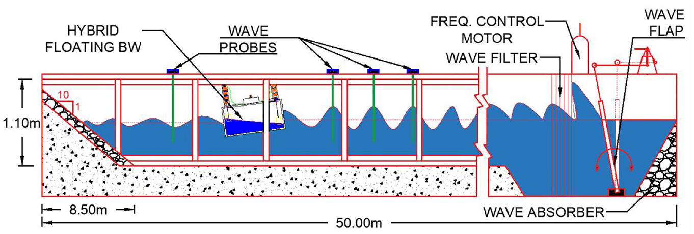
The Wave Flume at the Department of Water Resources and Ocean Engineering, NITK, Surathkal is 50 m long, 0.71 m wide, and 1.1 m deep, with a smooth concrete bed for 42 m and a 6 m long wave-generating chamber at one end and a beach with a 1V:10H slope made of rubble stones at the other end. A bottom-hinged flap-type wave generator is installed in the flume. A 7.5 HP, 11 kW, 1450 rpm induction motor powers the wave generator. This motor is controlled by an inverter (0–50 Hz) and rotates at 0–155 rpm. At a maximum water depth of 0.5 m, the system may generate regular waves with heights of 0.02–0.24 m and durations ranging from 0.8 to 4 s. Figure 3 is a longitudinal sectional view of a wave flume.
The longitudinal sectional view of wave flume.
Wave probes and data acquisition system
Depending on the wavelength, the wave probes are placed at predetermined distances in the flume on the seaward side of the hybrid floating breakwater model. The probes were placed at L, L + L/3, and L + 2L/3 distances from the front wall of a hybrid floating breakwater using Isaacson’s45 three-probe technique. The wave probes are calibrated before the experiment begins by setting the voltage value corresponding to the still water level to zero. Using appropriate equipment, the key parameter, wave surface height on the model’s seaward side, is converted into an electrical signal. A software-controlled 12-bit A/D converter with 16 digital input/output channels digitizes the electrical signal.
Calibration of the wave flume
To achieve the desired wave height at the structure location, a relationship must be established between the frequency of the motor, the eccentricity of the board, wave height, and wavelength for different wave periods at different water depths. The input to the motor varies by altering the frequency input through the inverter, and by changing the eccentricity of the flywheel, the stroke of the wave flap may be changed, resulting in waves of varying heights. As a result, the wave height depends on the frequency of the motor and the eccentricity of the board. The wave height produced by the wave flume is related to the eccentricity of the wave board, whereas the frequency of the inverter is inversely proportional to the wave period. Taking into account the distance between the wave paddle and the model as well as the wavelength , the number of waves in a burst required for the generation of acceptable wave heights and wave periods may be estimated. A burst of six waves is generated in the current experiment, and the digital voltage data gathered from the three wave sensors (probes) are translated into wave height and wave period. The technique is repeated at various water depths to get the wave height and period.
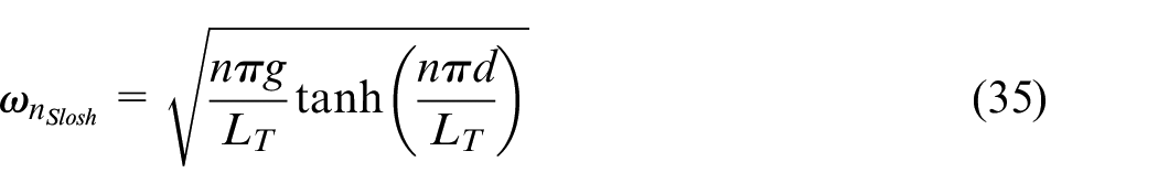
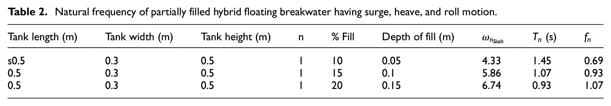
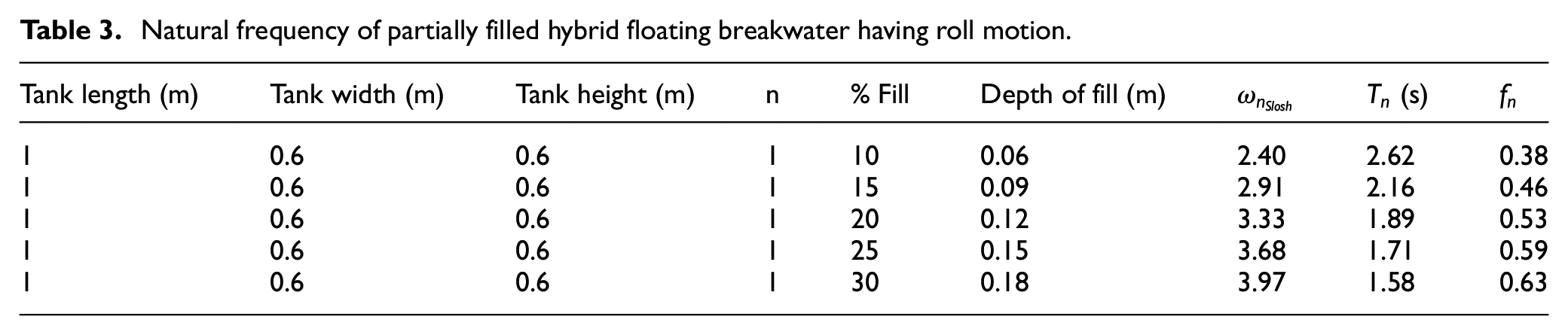
In the present study, the range of wave excitation frequency for which the sloshing natural frequency is achieved is first determined for the calibration of the floating breakwater integrated with the WEC model, as shown in Tables 2 and 3 respectively for a hybrid floating breakwater having roll and heave, and only roll degrees of freedom. In the case of a partially filled rectangular tank, the sloshing natural frequencies of the fluid46 is given by
Natural frequency of partially filled hybrid floating breakwater having surge, heave, and roll motion.
Tank length (m)
Tank width (m)
Tank height (m)
n
% Fill
Depth of fill (m)
(s)
s0.5
0.3
0.5
1
10
0.05
4.33
1.45
0.69
0.5
0.3
0.5
1
15
0.1
5.86
1.07
0.93
0.5
0.3
0.5
1
20
0.15
6.74
0.93
1.07
Natural frequency of partially filled hybrid floating breakwater having roll motion.
Tank length (m)
Tank width (m)
Tank height (m)
n
% Fill
Depth of fill (m)
(s)
1
0.6
0.6
1
10
0.06
2.40
2.62
0.38
1
0.6
0.6
1
15
0.09
2.91
2.16
0.46
1
0.6
0.6
1
20
0.12
3.33
1.89
0.53
1
0.6
0.6
1
25
0.15
3.68
1.71
0.59
1
0.6
0.6
1
30
0.18
3.97
1.58
0.63
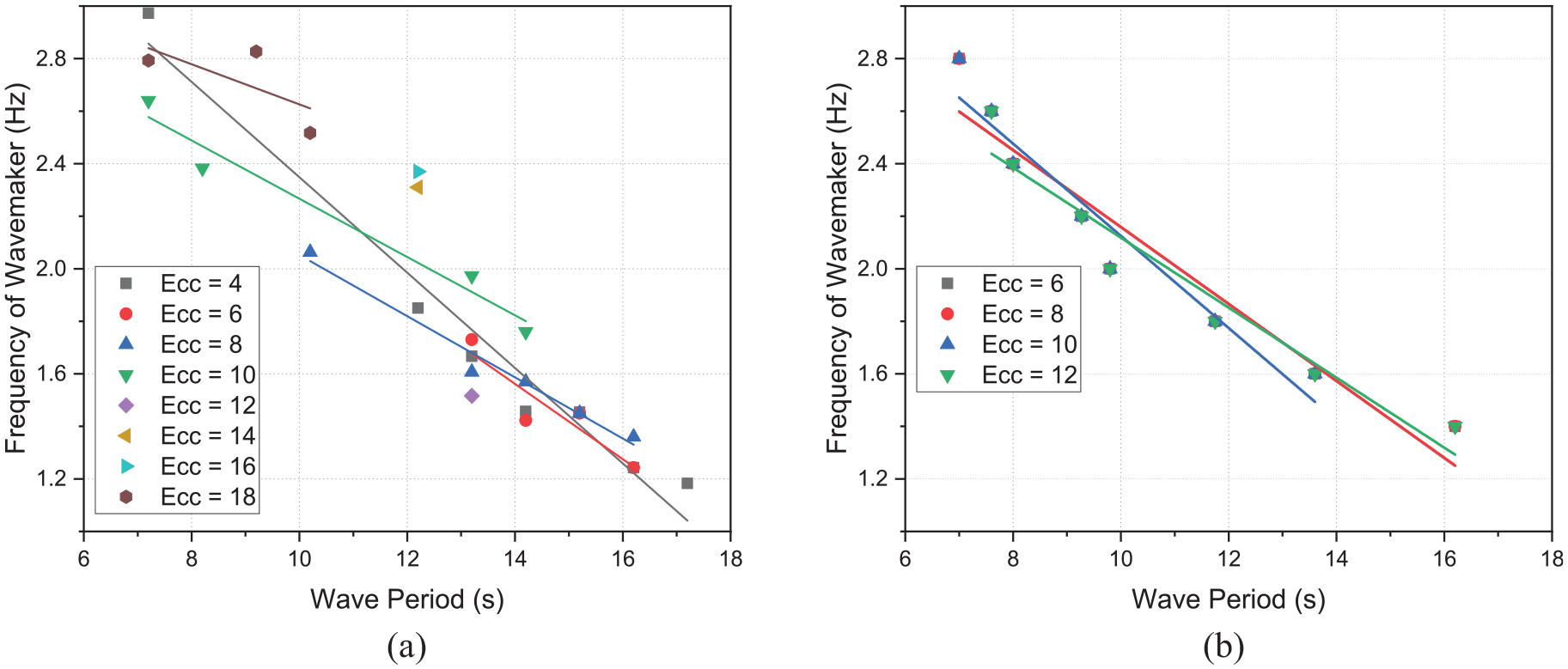
Three trials are repeated to minimize the influence of errors and increase the reliability of experiment outcomes. The wave flume is calibrated for water depths of 0.45 and 0.5 m, and a general relationship between frequency and wave period is derived using multi-regression analysis, as shown in Figure 4.
Calibration of wave flume for: (a) d = 0.5 m and (b) d = 0.45 m.
Description of hybrid floating breakwater with WEC
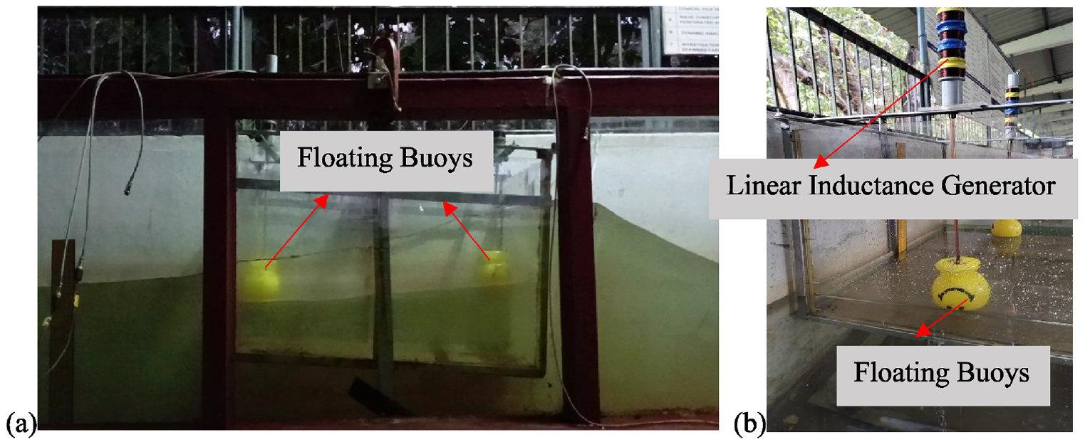
The hybrid floating breakwater is made of acrylic sheet and has a steel structure made of mild steel. It has a length of 1 m, a width of 0.6 m, and a depth of 0.6 m. Two floating buoys of negligible mass (weight less than 20 g) are mounted at the tank’s two extreme ends to absorb sloshing energy, which can then be transformed into power via the linear inductance generator, as shown in Figure 5.
Floating breakwater with built-in buoys connected with pairs of linear inductance generator: (a) longitudinal view and (b) front view.
The hybrid floating breakwater is oscillated externally in the wave flume by a bottom-hinged flap-type wave generator, which causes the internal sloshing motion. The sloshing waves then stimulate the floating buoys, causing them to drive the PTO system. Thus, mechanical energy is transferred from ocean waves to the floating structure, then to sloshing waves and oscillating buoys, and finally to the PTO system. The PTO system is built as a linear inductance generator that may generate an electrical current in the wire loop by relative motions between the wire loop and magnet, which is accomplished by allowing a permanent magnet to travel through a coil or vice versa. A cylindrical shaped permanent magnet of 25 mm diameter and 12 mm thickness of N52 Grade Neodymium set at 25 mm intervals in four numbers is used to construct the linear generator PTO. The copper wire is wound around a 40 mm diameter cylindrical PVC pipe to form a coil of 500 windings spaced by 25 mm and interconnected in series.
Experimental conditions
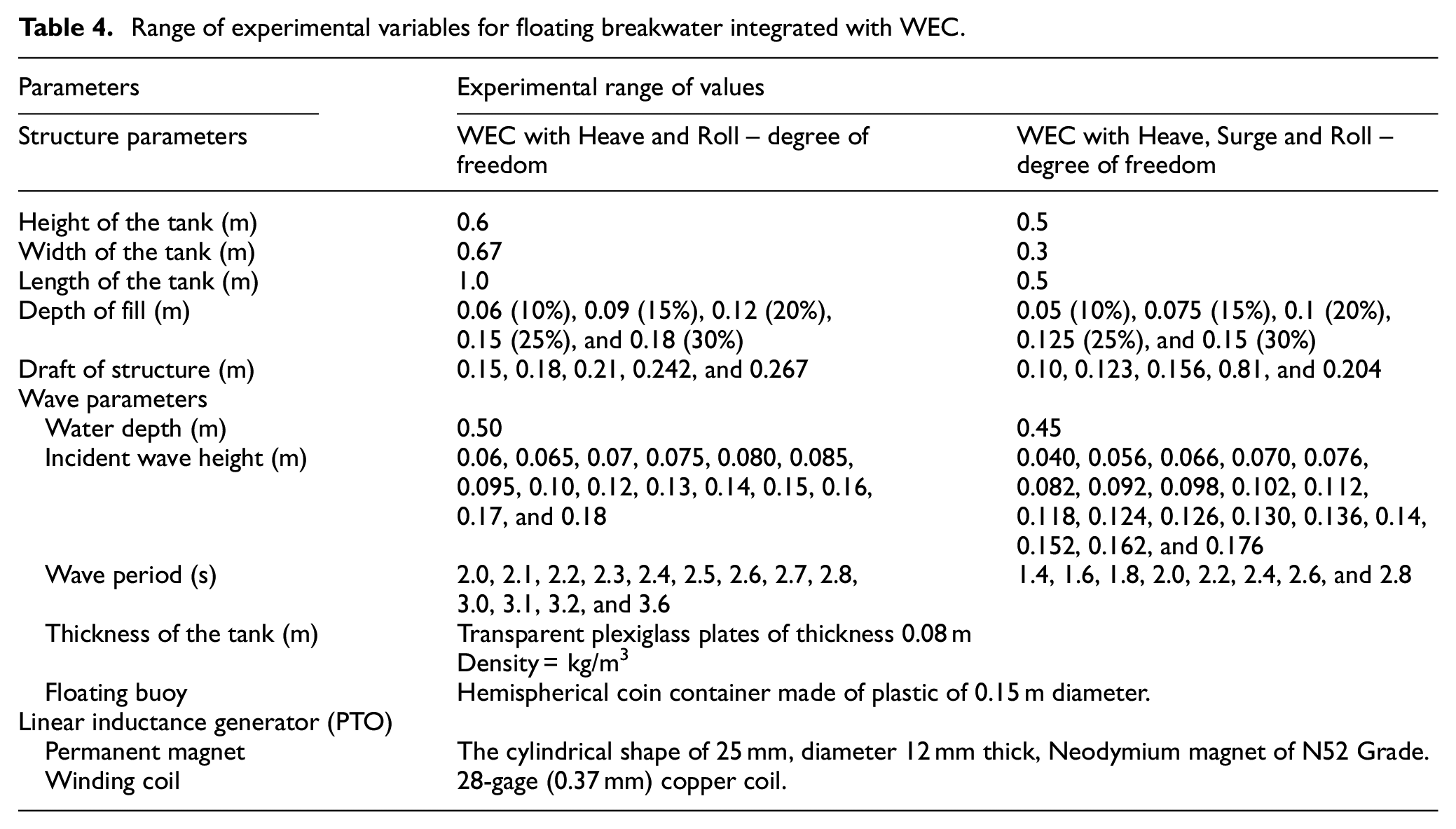
The wave flume bed is considered flat and solid, and the waves created are periodic, with secondary waves ignored. The density difference between freshwater and saltwater is neglected. The effect of reflection from the walls of the wave flume is neglected. The hydraulic efficiency of the test model is studied, but the effect of bottom friction is ignored. Table 4 shows the physical and wave parameters examined for the experimental study.
Range of experimental variables for floating breakwater integrated with WEC.
Parameters
Experimental range of values
Structure parameters
WEC with Heave and Roll – degree of freedom
WEC with Heave, Surge and Roll – degree of freedom
Hemispherical coin container made of plastic of 0.15 m diameter.
Linear inductance generator (PTO)
Permanent magnet
The cylindrical shape of 25 mm, diameter 12 mm thick, Neodymium magnet of N52 Grade.
Winding coil
28-gage (0.37 mm) copper coil.
To scale a floating body model to account for the different parameters, the Froude number can be used to compare the wave making resistance between bodies of various sizes and shapes given by , where is the Froude number, is the velocity, is the acceleration due to gravity and is a characteristic length of the structure. Further, to account for differences between freshwater and seawater, it is required to adjust the acceleration due to gravity () and the fluid density () as .
Numerical results and discussion
The numerical model using BEM is developed and the results are validated with the experimental results and the results available in the literature to examine the hydrodynamic performance and WEC efficiency of the hybrid floating breakwater system. The hydrodynamic coefficients such as added mass coefficients (, and ), radiation damping coefficients (, and ), response amplitude operator , heave motion response , hydrodynamic performance of breakwater measured in terms of wave reflection , wave transmission coefficient , and its capture width ratio which is a measure of the hybrid system’s wave energy conversion capability, are investigated for various structural parameters. The effect of modifying structural parameters, specifically relative drafts and relative structural width , on the suitability of the hybrid system as an efficient hybrid system is examined. Unless otherwise stated, the wave parameters such as seawater density , acceleration to gravity , incident wave amplitude and angle of incidence are kept constant throughout the analysis, and the percentage fill of liquid in rectangular tank is kept at 25%, which is considered a ballast mass in numerical analysis. The geometrical parameters of hybrid floating structure considered during the study are and , with the PTO damping coefficient of WEC system equal to its ideal value (). The wave energy efficiency is calculated considering heave motion only.
Validation of numerical and experimental results
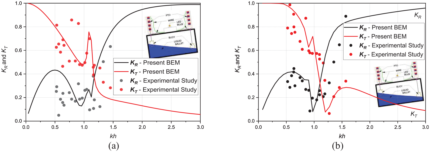
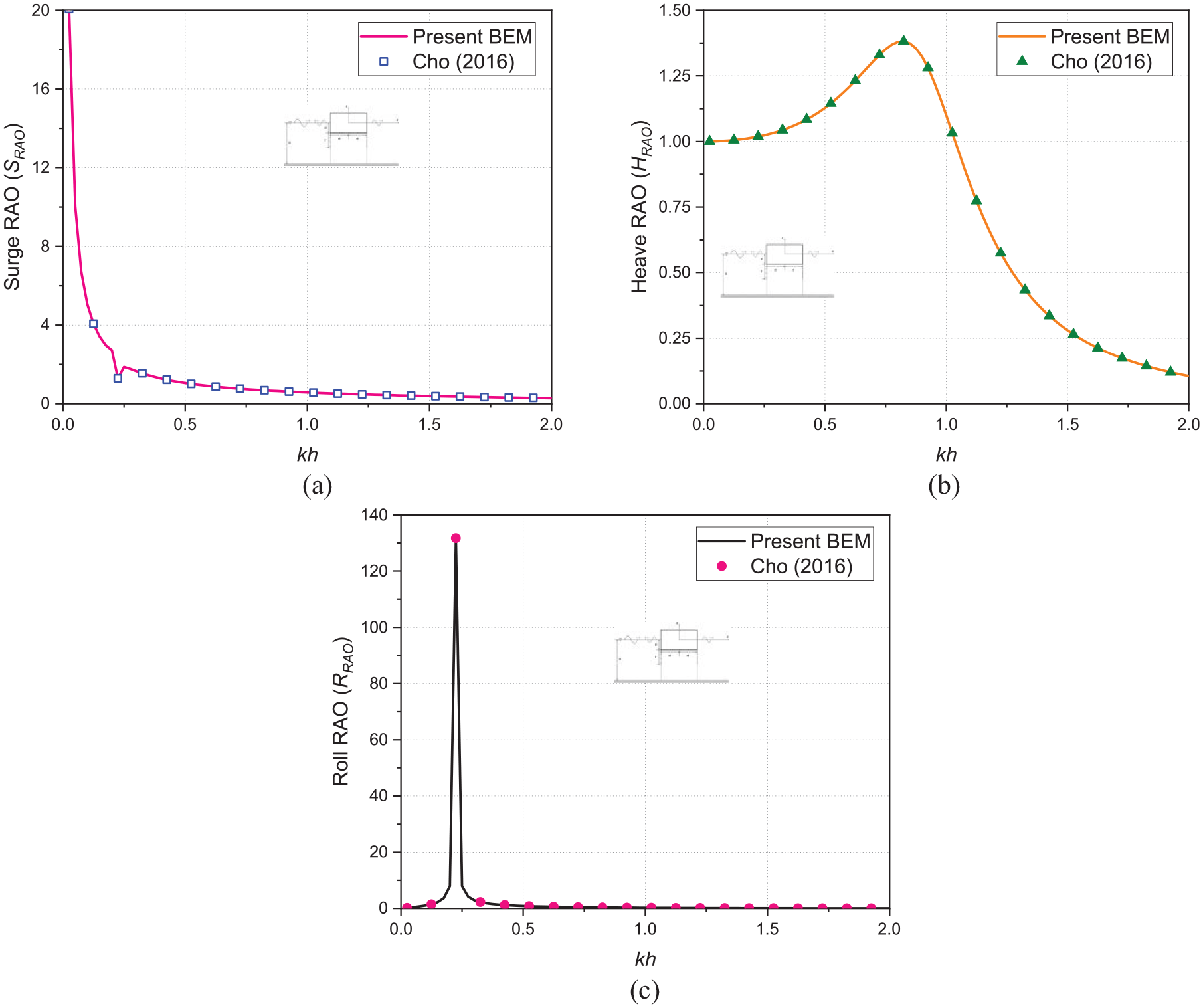
The validation of numerical and experimental results in terms of wave reflection coefficient and transmission coefficient is shown in Figure 6(a) and (b) for a rectangular tank of 15% filled liquid considering (a) constrained roll motion and (b) constrained surge, heave and roll motion, with the assumption of modest sloshing in the tank of the hybrid floating breakwater. Further, to check the correctness of numerical Boundary Element Method (BEM), the results obtained using the present BEM model for the surge RAO , heave RAO , and roll RAO is verified on comparing with the available results of Cho47 for a rectangular floating breakwater (Figure 7(a) and (b)) with the structural parameters , and incident wave amplitude .
Comparison of and versus using numerical and experimental investigation of a hybrid floating breakwater for 15% fill of liquid ballast, with constrained: (a) roll degrees of freedom and (b) heave, surge and roll degree of freedom.
Validation of: (a) Surge RAO , (b) Heave RAO , and (c) Roll RAO versus the nondimensional wavenumber considering and .
The comparative study presented in Figure 6(a) and (b) are in good agreement over a narrow frequency range , while over a wider frequency range, the experimental findings are found to be lower than the numerical results. This could be owing to the fact that the numerical findings of BEM are based on linear small amplitude wave theory, with the basic assumptions of fluid as inviscid, incompressible and the accompanying motion is irrotational, while the wave nonlinearity at the weather side of the hybrid floating breakwater is strong. In addition, it is assumed in the numerical computations that the PTO has a negligible mass, that there is no friction between the constraints, and the liquid in the tank is static.
Further, the surge, heave, and the roll response operators (, , and ) analyzed against the non-dimensional wave number is shown in Figure 7(a) and (b), which is consistent with the results reported by Cho.46 Finally, the present BEM approach for wave reflection coefficient and transmission coefficient presented in Figure 6(a) and (b) and the surge, heave, and the roll response operators (, , and ) for a rectangular floating breakwater utilizing the aforementioned parameters agrees satisfactorily with the experimental results and Cho.47
Parametric study of hybrid floating breakwater
The hydrodynamic coefficients of the hybrid floating breakwater, such as added mass coefficients (, and ), radiation damping coefficients (, and ), and response amplitude operators for surge , heave , and roll , Capture Width Ratio (), reflection coefficient and transmission coefficient are significantly influenced by the relative structural width and relative structural draft , are examined while maintaining the optimal PTO damping = . The operational efficiency of the hybrid system is evaluated using two criteria (i) effectiveness as a breakwater in terms of wave reflection and transmission coefficients with a threshold value of as defined in Goda48 and (ii) effectiveness as a WEC device in terms of capture width ratio with a threshold level of efficiency , as considered in Zhao et al.36
Effect of relative structural width
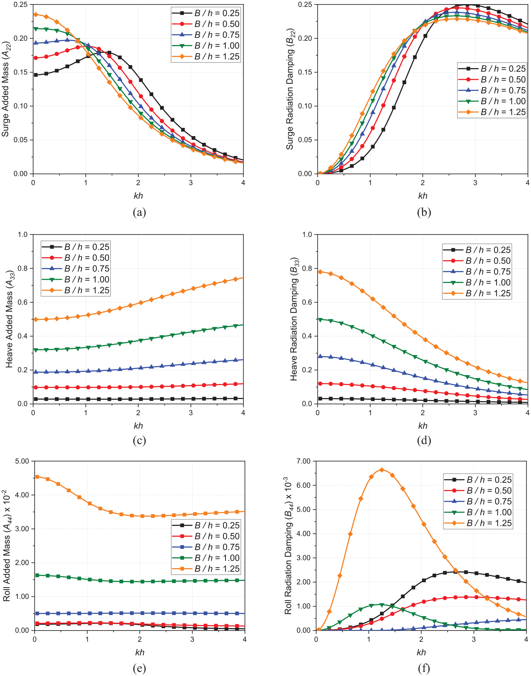
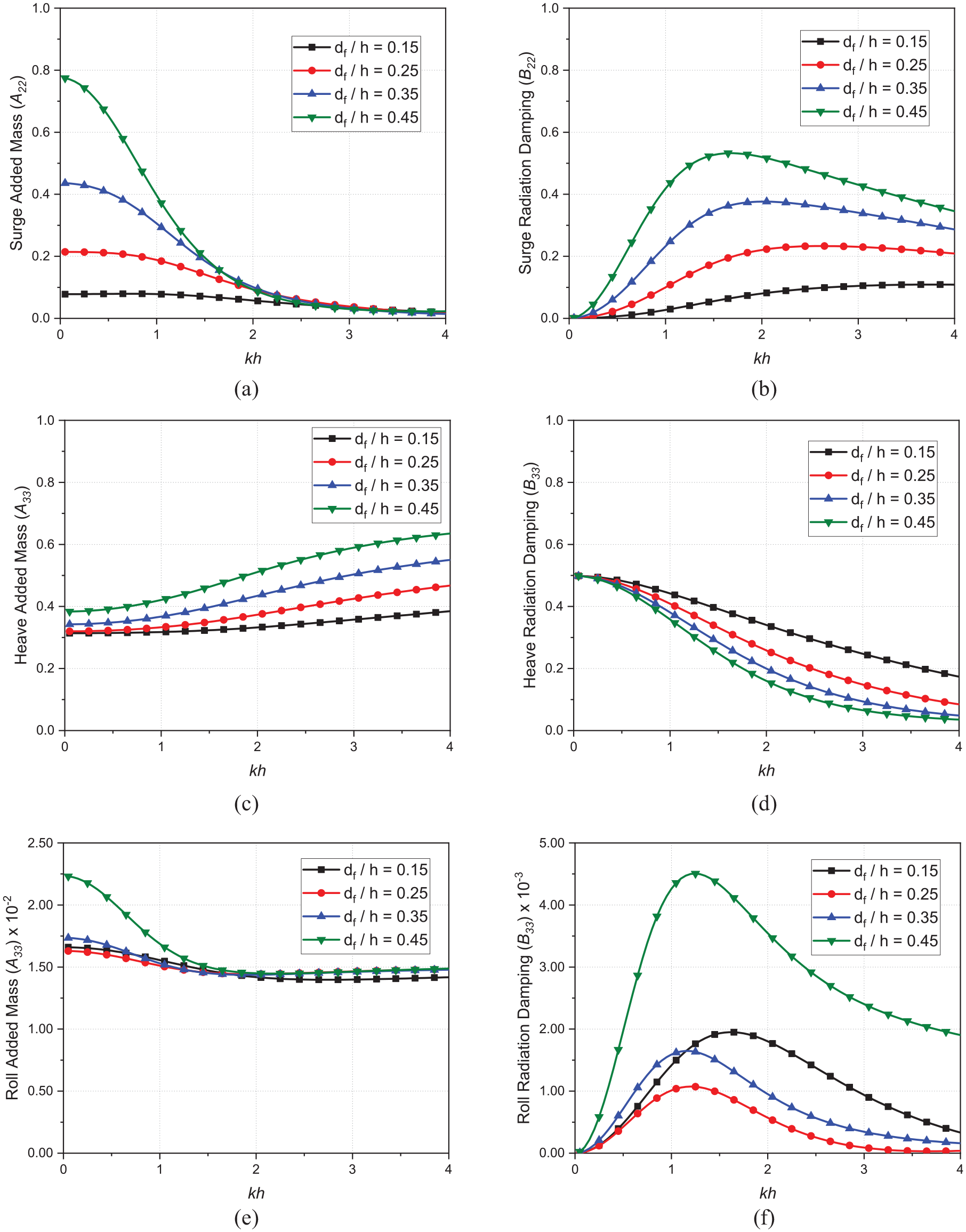
The effect of varying the structural width of the hybrid floating breakwater system on the hydrodynamic properties of the system is investigated while maintaining a constant structural draft . Figures 8–12 illustrates the variations of the hydrodynamic coefficients such as added mass (, and ), radiation damping (, and ), surge, heave and roll response amplitude , , and ), capture width ratio (), wave reflection coefficient and transmission coefficient against the non-dimensional wavenumber . The effect of increasing the relative structural width on the hydrodynamic added mass and radiation damping coefficients for a constant structural draft is depicted in Figure 8(a) and (b), which clearly indicates that the surge added mass and accompanying radiation damping increase until their cross-over points, which is noted in intermediate water depth region within .
Variation in: (a) surge added mass , (b) surge radiation damping , (c) heave added mass , (d) heave radiation damping , (e) roll added mass , and (f) roll radiation damping versus the varying nondimensional wave number for different relative structural width .
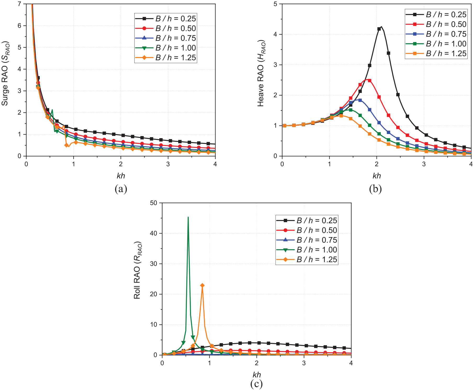
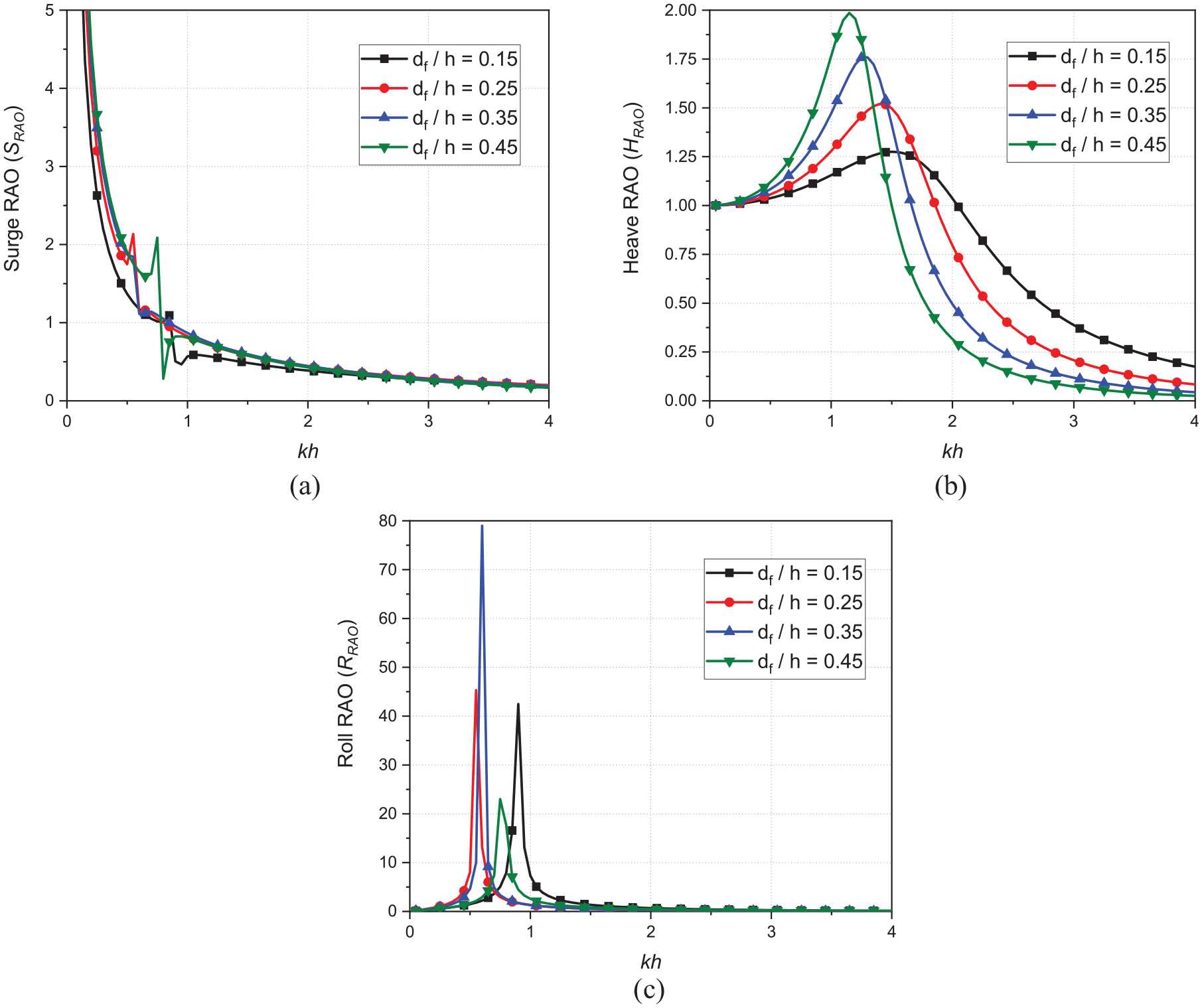
Variation in (a) surge RAO , (b) heave RAO , and (c) roll RAO versus the nondimensional wavenumber for varying relative structural width .
Variation in wave reflection and wave transmission coefficient versus the nondimensional wavenumber for varying relative structural width constrained to: (a) Surge, (b) Heave, and (c) Roll degrees of freedom system.
Variation in wave reflection and wave transmission coefficient versus the nondimensional wavenumber for varying relative structural width constrained to: (a) Surge-Heave (b) Heave-Roll, and (c) Surge-Roll degrees of freedom.
Variation in: (a) wave reflection and wave transmission coefficient for a freely floating system with Surge, Heave and Roll degrees of freedom and (b) capture width ratio versus the nondimensional wavenumber for varying relative structural width .
In addition, the surge added mass and radiation damping coefficients reduce in magnitude by about 5% with increasing structural width . The heave added mass and the radiation damping coefficients (Figure 8(c) and (d)) initially increase approximately by twofolds with increase in relative structural width. However, the heave added mass and the radiation damping coefficients does not vary with increasing wavenumber for relative structural width , whereas for , the heave radiation damping decrease with increasing wavenumber which is exactly an opposite trend as that of heave added mass coefficient . The effect of altering structural width on roll added mass and radiation damping coefficients is illustrated in Figure 8(e) and (f). The prominent characteristics of hydrodynamic coefficients not only show a rise in magnitude, but also a phase shift toward lower wavenumber , which is primarily attributable to a drop in the fundamental natural frequency with increasing relative structural width . Similar observation is noted by Elchahal et al.49
Although the surge added mass and radiation damping coefficients (Figure 8(a) and (b)) is increasing with increase in relative structural width in shallow water depth region .The variation of the structural width has limited effect on surge response amplitude operator (Figure 9(a)) in shallow water depth region and it is reducing in its magnitude in intermediate and deep-sea region .The probable reason is that, the increasing structural width while maintaining a constant relative structural draft will increase the mass of the system while the wetted surface that contributes toward the surge response is not altered.
The surge response amplitude operator demonstrates its resonant value much greater than 7 for all the relative structural widths . In shallow water depth, the surge response amplitude operator vertically drops to a value of and then linearly decreases in its magnitude as proceed to intermediate and deep-sea region to attain its value of . It is also noteworthy that the resonance in surge response amplitude operator occurs at low-frequency waves, as observed by Li and Bachynski.50 While the heave response amplitude operator (Figure 9(b)) has an ideal value of for the wide range of wave numbers , thereby indicating that the motion of the structure follows the water surface. However, increasing structural width within with an interval of 0.25 not only leads to reduction in the resonant peak amplitude by 40.83%, 26.49%, 17.85%, and 12.75% respectively, but also there is a shift in their resonant peaks of toward lower wave number . The increase in structural breadth leads to a rise in the system’s mass and hydrodynamic restoring force , which ultimately causes a decrease in the fundamental natural frequency . The resonant peak value of roll response amplitude operator illustrated in Figure 9(c) decreases by 61.61% and 79.18% by increasing the relative structural width and . Further, increasing over a minimum required , triggers the resonant peaks of roll response amplitude operator as compared to those with and a frequency shift phenomenon is observed. Thereafter, any increase in relative structural width , the roll response amplitude operator not only shift toward the higher wave number but also considerable reduction in magnitude of about 97.89% is observed. This could be due to the increasing structural width decreases the system’s fundamental natural frequency causing the resonance to shift to a lower wave number . However, once the threshold excitation frequency is reached, increasing structural width may require a larger magnitude of wave excitation force to restore the anti-roll moment, which explains the shift in the resonant wave frequency toward higher wavenumber , but this shift lowers the roll response amplitude operator magnitude as compared to its threshold excitation frequency because it may not resemble its fundamental natural frequency .
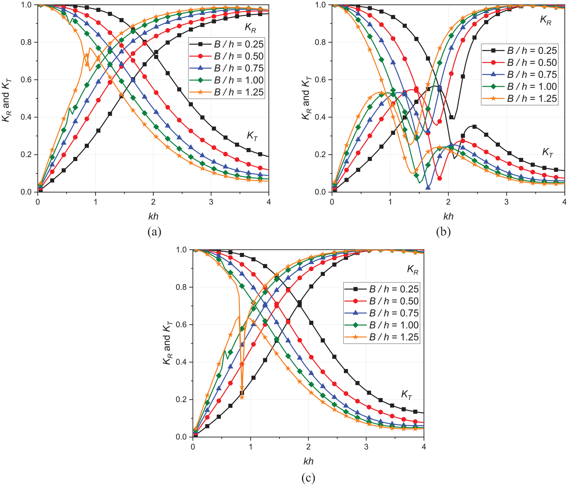
Figure 10(a)–(c) presents the wave reflection and transmission characteristics for a hybrid system for varying structural with constrained to separate surge, heave, and roll degrees of freedom. The wave reflection and wave transmission coefficients decrease as the structural width increases. In addition, the structural width is beneficial in increasing the performance of the hybrid system as a breakwater for wide range of frequencies, as the threshold level of the wave transmission coefficient is obtained at lower wave number with increase in structural width .
The reason for the decrease in and is that as the structural width of the floating structure increases, more wave energy is dissipated, indicating that the breakwater is more effective, as reported by Peña et al.51 during their experimental studies on floating breakwaters and Patil and Karmakar26 by numerical investigation on hydrodynamics of floating tunnel with submerged rubble mound breakwater. The salient features of designing in the hybrid system to have separate surge, heave and roll degree of freedom as illustrated in Figure 10(a)–(c) respectively indicates that, the surge and roll degree have similar wave transformation characteristics except the cross-over of wave reflection and transmission coefficients in rolling hybrid system are occurring at lower wavenumber with reduced amplitudes of around 5% with increase in structural width as compared to surging hybrid system. However, the heaving hybrid system notably suppresses the wave reflection and transmission coefficients followed by a shift toward lower wave number with increasing structural width up to a value of . Further, increasing structural width leads to a marginal increase in transmission coefficient , while the reflection coefficient continues to decline. It is noticed that despite the transmission coefficient being extremely close to zero at the structural width value of , the reflection coefficient is still well below the threshold value of 0.6. Interestingly in Figure 10(b) the crossover points at which wave reflection and wave transmission coefficients are almost equal to 0.5, while the capture width ratio is also close to 0.5. The finding indicates that 25% of the incident wave energy is reflected toward seaward side, 25% is transmitted toward the leeward side, and the remaining 50% is absorbed.
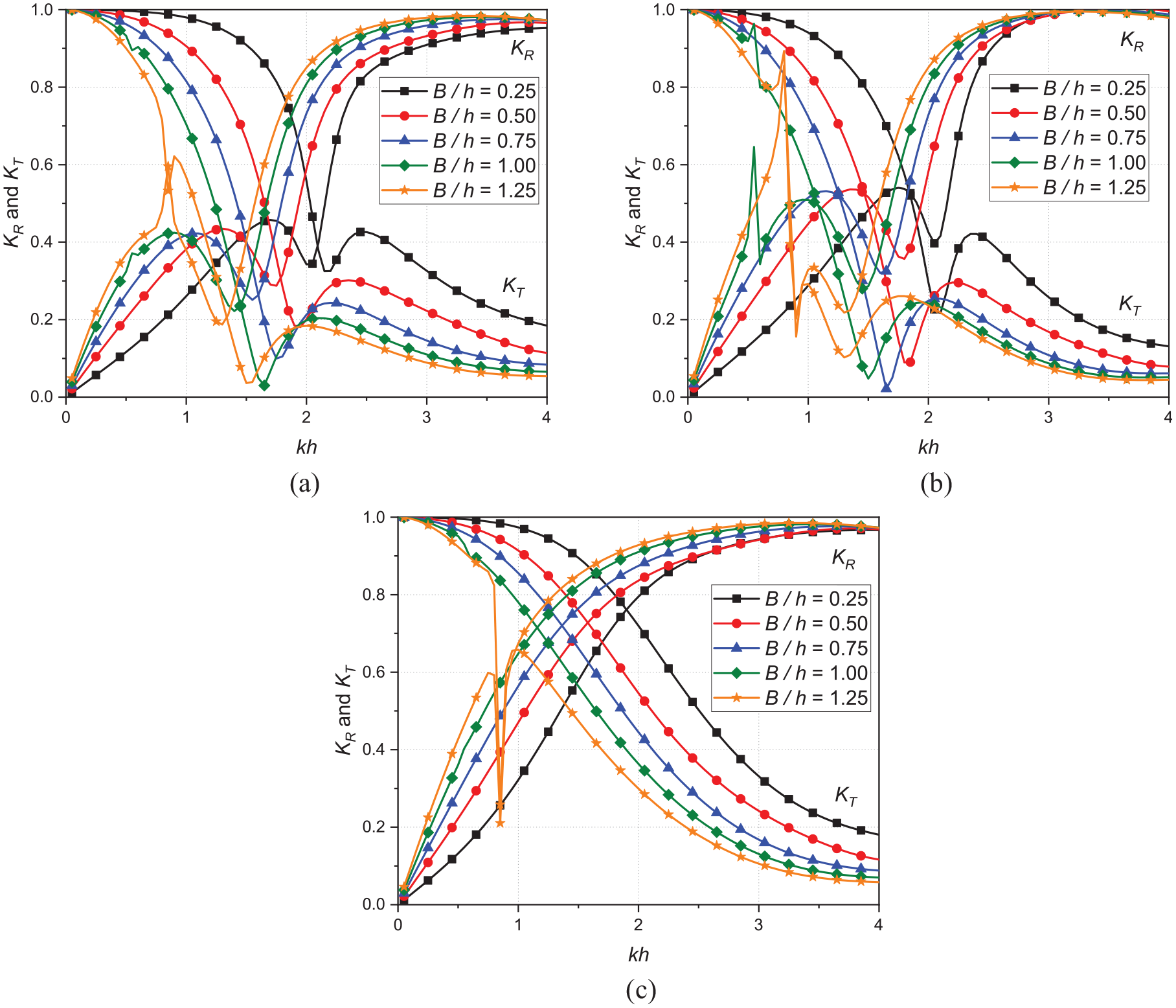
Figure 11(a)–(c) shows the effect of varying structural width on wave reflection and wave transmission coefficient against the nondimensional wavenumber for a coupled motion of a hybrid system designed to have (a) Surge-Heave (b) Heave-Roll, and (c) Surge-Roll degrees of freedom. Similar to Figure 10(a)–(c), on increasing the structure width results in a broadening of the frequency bandwidth for which the stated threshold limit of the wave transmission coefficient is observed. Coupling heave with either surge or roll degrees of freedom enhance the wave transformation characteristics as compared to coupling with surge with roll. This is due to the fact that surge and roll have similar wave transformation characteristics as observed in Figure 10(a)–(c). However, wave transformations of a coupled heave with roll degree of freedom are identical to only heave degree of freedom. This observation corroborates to the findings that hybrid system constrained to heave motion have better wave transformation characteristics as compared to other systems.
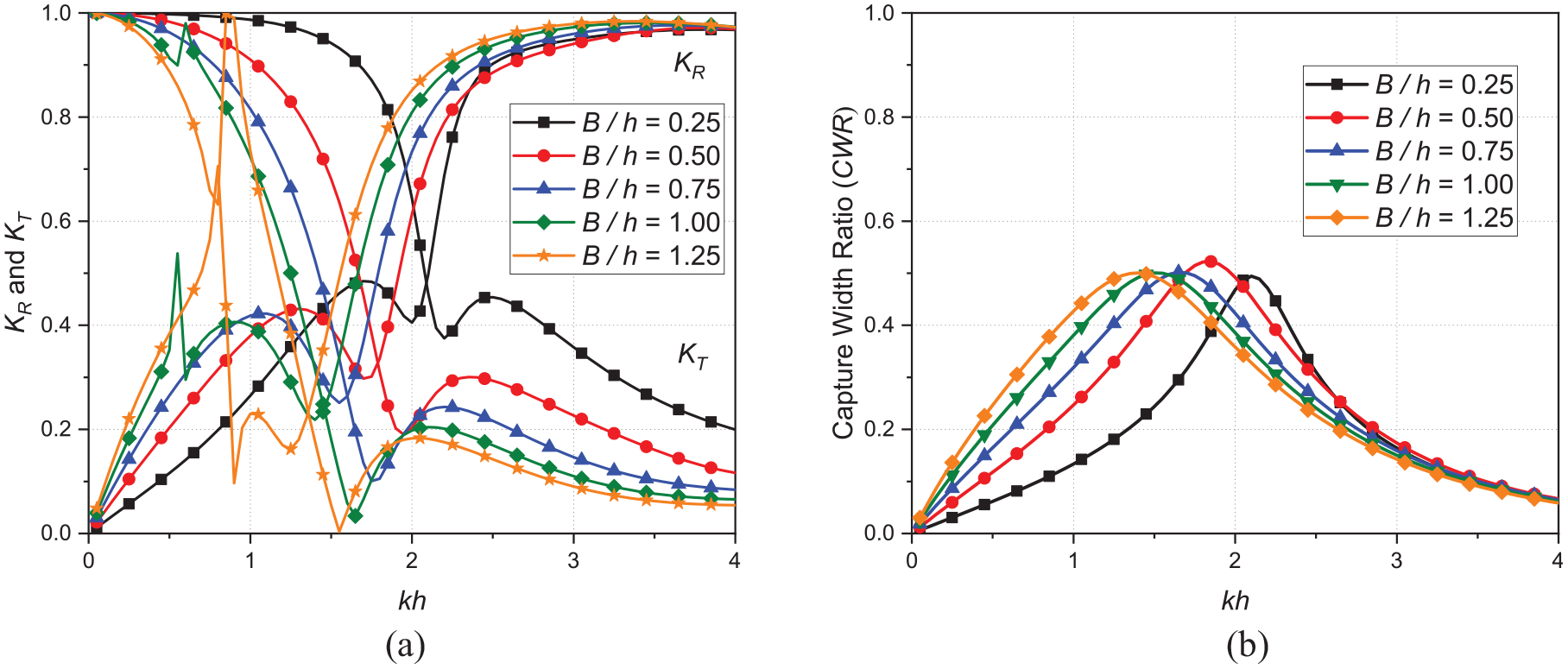
Figure 12(a), shows that, the wave reflection and transmission coefficients is decreasing with increase in structural width of the hybrid freely floating structure, but the wave transformation characteristics for a freely floating structure have higher wave reflection and transmission coefficients as compared to those hybrid structures with separate degrees of freedom. Increasing structural width beyond exhibits multiple spikes, wherein it has two cross-over point along with full wave transmission () and zero-wave transmission () are also recorded at different . On the other hand, the capture width ratio () shown in Figure 12(b) indicates that, the maximum capture width ratio is around (), which is identical for all the relative structural widths considered in the present study. The area under the capture width ratio increases by 25.88%, 2.51%, 2.88%, and 1.38% for every 0.25 increase in structural width within . While the percentage increase may be negligible for wider structural widths, the capture width ratio () exhibits a shift toward lower wave number due to the reduction in the fundamental natural frequency as the structural width of the floating structure increases.
Effect of relative structural draft
The effect of altering the relative structural draft , while maintaining a constant relative structural width and using PTO damping = on the hydrodynamic coefficients, performance of the breakwater, and WEC energy capture efficiency of the hybrid system is investigated. The resulting hydrodynamic coefficients such as added mass (, and ), radiation damping (, and ), surge, heave and roll response amplitude operators (, , and ), capture width ratio (), wave reflection coefficient , and transmission coefficients against the non-dimensional wavenumber are presented in Figures 13–17 respectively for various values of relative structural draft . The effect of increasing the relative structural draft on the hydrodynamic added mass and radiation damping coefficients for surge at depicted in Figure 13(a), clearly indicates that the surge added mass is double in magnitude for every increments of initially in shallow water region, converges to a single line in intermediate water depth region at . On the other hand, the surge radiation damping increases with increase in as well as with increasing wave number . As observed in Figure 13(c) and (d), the heave added increases with increase in both structural draft as well as wavenumber , whereas the heave radiation damping mass shows an opposites trend.
Variation in: (a) Surge added mass , (b) Surge radiation damping , (c) Heave added mass , (d) Heave radiation damping , (e) Roll added mass , and (f) Roll radiation damping versus for different structural widths .
Variation in: (a) Surge RAO , (b) Heave RAO , and (c) Roll RAO versus the nondimensional wavenumber for varying relative structural draft .
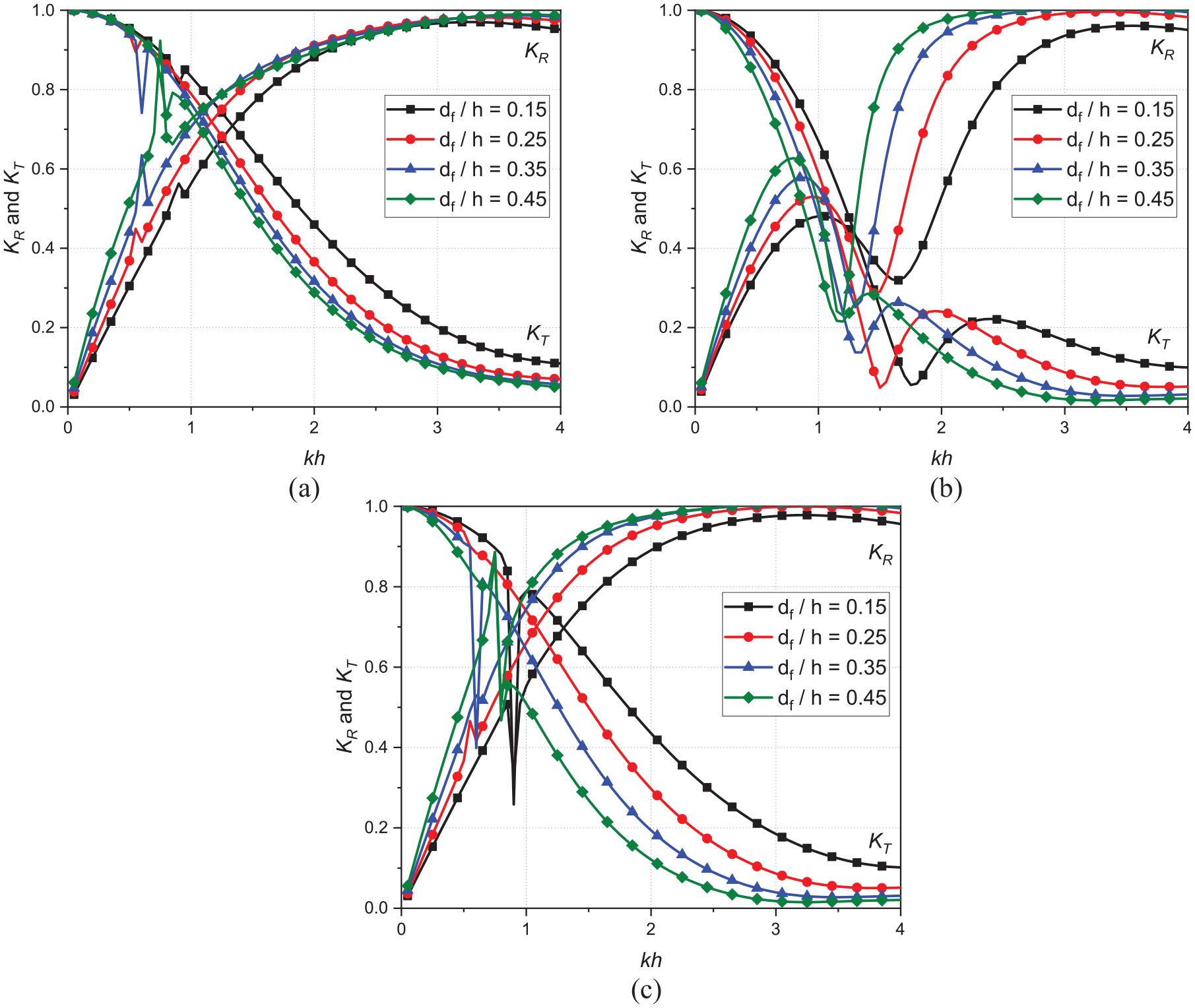
Variation in: and versus for varying relative structural draft constrained to have (a) Surge, (b) Heave, and (c) Roll degrees of freedom.
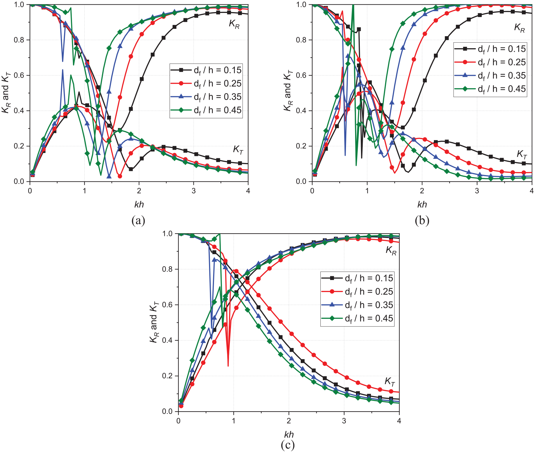
Variation in wave reflection and wave transmission coefficient versus for varying relative structural draft constrained to have: (a) Surge-Heave (b) Heave-Roll, and (c) Surge-Roll degrees of freedom.
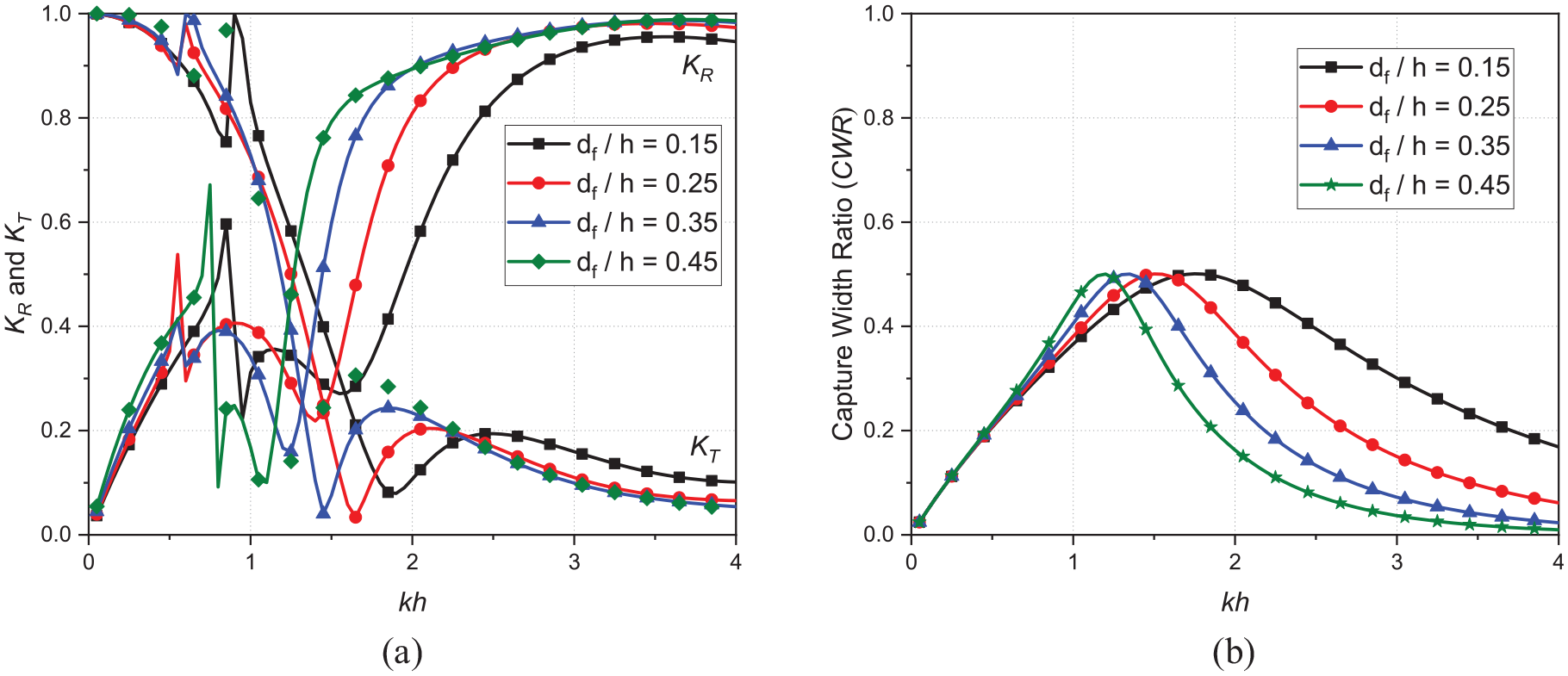
Variation in: (a) wave reflection and wave transmission coefficient constrained to have Surge, Heave and Roll degrees of freedom system and (b) Capture Width Ratio versus nondimensional wavenumber for varying relative structural draft .
It is also worth noting that the deep-sea state has almost double the magnitude of the heave added mass (Figure 13(c)) and radiation damping (Figure 13(d)) as compared to the shallow water condition. This means that the heave amplitude operator has a larger magnitude and a phase shift toward a lower wave number in the shallow water depth, as apparent in Figure 14(b). The effect of increasing structural draft on roll added mass (Figure 13(e)) is largely unaffected for all the wave number except for in shallow water depth region. While the roll radiation damping (Figure 13(f)) is reduced on an average of 20% for increase in to 0.25, further increasing to 0.35, roll radiation damping increases by an average of 5%–7% and then increasing to 0.45 a notable increase of around 40% on average is recorded.
While the trends depicted in Figures 9(a)–(c) and 14(a)–(c) are similar, the magnitudes of the amplitude operators for the roll and surge responses ( and ) are significantly greater in Figure 14(b) than they are in Figure 9(b). Conversely, the magnitude of the amplitude operator for the heave response is considerably lower in Figure 14(b). This is due to the fact that as the relative structural draft is increased, the vertical wetted surface and the lever arm for rolling also increase, thereby capturing a greater quantity of surge and roll radiation force. As a consequence, the magnitudes of surge and roll amplitude ( and ) operators are more effectively amplified. However, the contribution of the wetted surface to the amplification of heave radiation forces remains constant, and the variation in water wave pressure along the water depth has a negligible effect on heave radiation force amplification. Furthermore, by adjusting the relative structural draft while keeping the relative structural width constant, the hydrodynamic restoring force remains unchanged. Nevertheless, the mass undergoes inherent variability, which induces a shift in the system’s fundamental natural frequency . This shift in turn influences the heave and roll response ( and operators, which point toward lower wavenumbers , which represent the motion response and hydrodynamic coefficients that are regulated by the damping mechanism of the system.
As illustrated in Figure 15(a)–(c), the float stability of the hybrid floating structure improves with increasing draft . This leads to an average 5% increase in the wave reflection coefficient and a corresponding reduction in the wave transmission coefficient for systems featuring surge and roll degrees of freedom. Additionally, substantial increase in wave transmission coefficient and wave reflection are detected in surge and roll hybrid systems at wave numbers that correspond to the fundamental natural frequency of the system. The wave reflection coefficients shift to higher wavenumbers as the structural draft increases, while the wave transmission coefficients shift to lower wavenumbers , resulting in lower reflection and transmission coefficients for systems designed for heave degrees of freedom as shown in Figure 15(b) for a particular wave number under consideration. Overall, for system that is designed to have separate heave degree of freedom demonstrates to have wider frequency bandwidth, for which both the wave reflection and transmission coefficients are less than the set threshold value of 0.6 and the bandwidth reduces with increasing structural draft . For the other two systems that are designed to have separate surge or roll degree of freedom system, there is no wave number for which both the wave reflection and wave transmission coefficients are less than the threshold value of 0.6. However, for all these three hybrid systems, the wave transmission coefficient with , are observed to occur in the intermediate water depth region with .
Figure 16(a)–(c) shows the effect of varying structural width on wave reflection and wave transmission coefficient against the non-dimensional wavenumber for a coupled motion of a hybrid system designed to have (a) Surge-Heave (b) Heave-Roll, and (c) Surge-Roll degrees of freedom. It is observed that coupling the surge-heave and heave-roll as in Figure 16(a) and (b) respectively, will enhance the wave attenuation characteristics of the hybrid systems especially by reducing the wave reflection coefficients in shallow and part of the intermediate water depth region. Thus, enabling these systems to satisfy the set criteria of both wave reflection and wave transmission coefficient less than 0.6. Since the wave transformations of a separate surge and roll system as in Figure 15(a) and (c) respectively are identical in magnitude, so coupling surge-roll would not benefit in improving the wave transformation of such system.
For the freely floating structure depicted in Figure 17(a), the impact of increasing structural draft on wave reflection and wave transmission coefficients is negligible in shallow water depth and a portion of the intermediate water depth region . While the transmission coefficients reduces and wave reflection coefficients increases with the increase in the draft , except for the wavenumbers and respectively for which the trend is opposite. Similar to the surge-heave and heave-roll coupled hybrid structure as in Figure 16(a) and (b) respectively, the freely floating structure not only exhibits better wave attenuation characteristics by satisfying the set criteria of both wave reflection and wave transmission coefficient less than 0.6, but also demonstrates higher wave energy dissipation characteristics as cross-over points of wave reflection and wave transmission coefficient are much lower than 0.4. However, increasing structural draft will be beneficial for substantial reduction in wave transmission coefficients, but on the other side it ends up in raising the wave reflection coefficient in deep sea zone, which may lead to formation of standing waves. Interestingly, a mirrored pattern of capture width ratio is observed on comparing the Figures 12(b) and 17(b). The effect of structural draft on has no influence on the capture width ratio in shallow water depth and part of the intermediate water depth region for . Further, for , the capture width ratio decreases with increase in draft of the floating structure. Since, the wave energy tends to be concentrated around the water’s surface as we approach to deeper sea states, raising the structures draft should mitigate the vertical component of wave power responsible for heave. The area under the capture width ratio curve reduces by 21.62%, 19.67%, and 16.47% for every 0.1 increase in structural draft within . It is noteworthy that for a relative draft of has wider frequency bandwidth of .
Experimental investigation on hybrid floating breakwater
Seaports are high-energy-demanding facilities that are vulnerable to wave energy, a plentiful but largely untapped resource. As a result, there is growing interest in incorporating wave energy converters (WEC) into seaport breakwaters. The experimental investigation is carried out to analyze the hydrodynamic performance characteristics of a floating rectangular-shaped box-type breakwater with partially filled liquid in terms of wave reflection and transmission coefficient, as well as to convert the partially filled liquid sloshing dynamics into electricity. Zhang et al.41 conducted similar experimental and numerical studies on the sloshing-WEC device by giving a harmonic excitation on a shaking table along the length side of the tank, with a displacement amplitude of 0.01 m for a constant fill in a tank of dimension 0.5 m × 0.2 m × 0.6 m. In the present study, the floating rectangular-shaped box-type breakwater is subjected to a roll motion and external wave-induced force generated by a frequency-controlled wave generator in a two-dimensional wave flume for various wave heights as mentioned in Table 4. Due to the roll excitation, the partially filled liquid in the tank sloshes, causing the liquid to rise and fall along the tank’s side walls. Due to the buoyancy of the floating buoy, the rise and fall of the liquid intern induces linear motion in the PTO, and thus wave energy is absorbed through the sloshing of a liquid filled in the floating breakwater as a ballast, which is further transformed into mechanical energy and then to electric energy through the PTO. As a result, the ensuing wave transmission coefficient on the leeward side is decreased, proving that the hybrid floating breakwater is both useful to port operations and capable of capturing wave energy.
Wave reflection and transmission coefficient
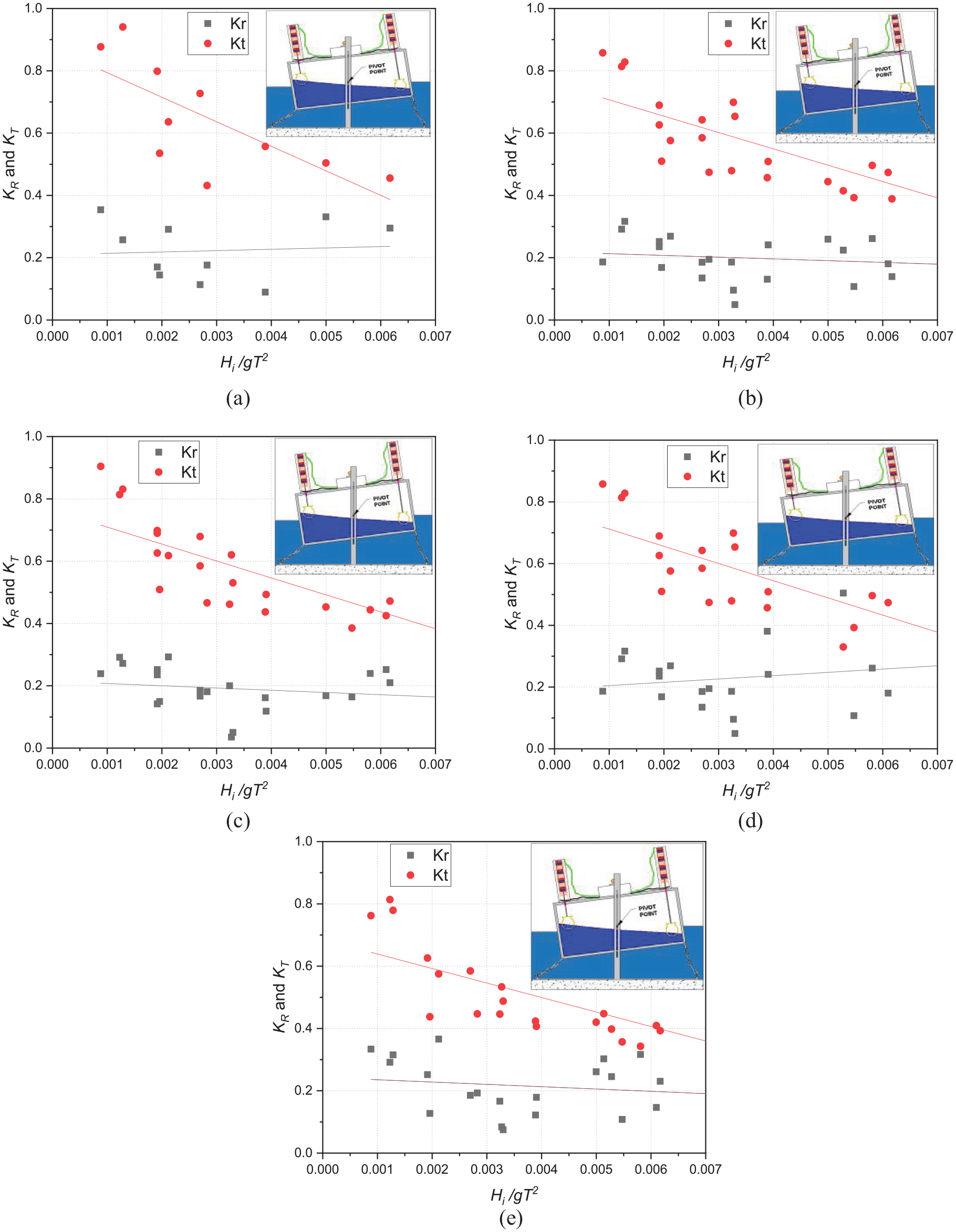
The surface floating breakwater aids in the attenuation of surface waves due to the wave reflection and transmission coefficient mechanisms. The present investigation is performed experimentally with the goal to establish an efficient hybrid floating breakwater capable of wave energy conversion and optimizing the wave transformation characteristic. Figure 18(a)–(e) depicts the resulting wave reflection and transmission coefficient against the wave steepness parameter for varying depth of fill within 10% < d < 30% respectively. The threshold value of wave reflection and transmission coefficient is considered as 0.6 as defined in Section 4.2. However, for safe and efficient operations, the operability thresholds are established by the maximum allowed ship movements caused by the met-ocean conditions.52 The wave transmission coefficient reduces with increasing for all the depth of fills , as seen in Figure 18(a)–(e), since simply escape without interacting with the hybrid floating breakwater. The water column mass interacting with the hybrid floating breakwater grows as increases, providing energy to the structure’s body, which is further reduced by the sloshing of a liquid in the tank, resulting in a decreased wave transmission coefficient . On the other hand, the wave reflection coefficient seems to remain much lower than the set threshold wave reflection for all the depth of fill and with increase in the reflection coefficient slightly increases. As the depth of fill in the hybrid floating breakwater increases it will not only add to float stability but also contributes in reduction in the wave transmission coefficient. This is due to the fact that, the increased draft of the hybrid floating breakwater achieves stable equilibrium as the metacentric height shifts significantly above the center of gravity. In fact, the decrease is significant below the set threshold wave transmission coefficient , for the percentage depth of fill d ⩾ 15%. The wave reflection coefficient on the other hand, which originally increased with rising wave height for d = 10%, will remain unaltered for greater depth of fill. For depth of fill d ⩾ 20%, the wave transmission coefficient stays lower than the set threshold for incident wave heights .
Wave reflection and transmission coefficient versus non-dimensional wave height for: (a) 10% depth of fill, (b) 15% depth of fill, (c) 20% depth of fill, (d) 25% depth of fill, and (e) 30% depth of fill.
Wave runup in the partially filled hybrid floating breakwater
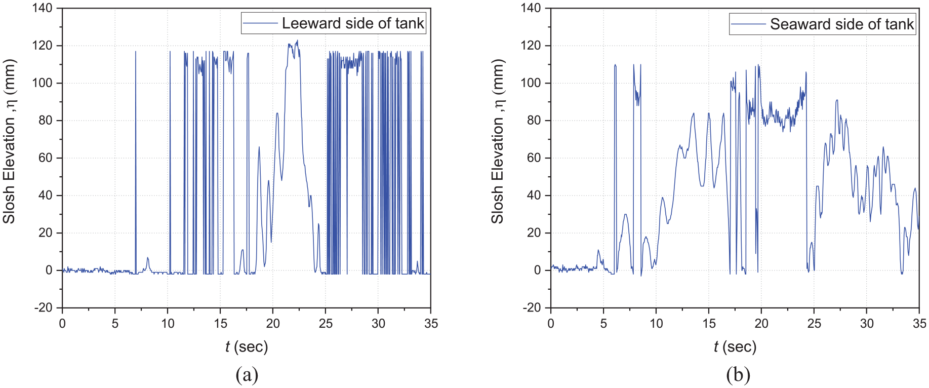
The runup probes affixed to the inner face of the tank’s front and rear walls were used to quantify the liquid displacement caused by sloshing in the partially filled hybrid floating breakwater during the roll motion when the incident waves interact with the structure as shown in Figure 19(a) and (b). The rate of movement of the permanent magnet in the linear inductance generator is determined by the quantum of rise and fall of liquid in the tank and its variation with respect to time . The greater the fluid displacement and impulsive rate of change with respect to time , the greater the magnetic flux through the copper windings of the linear induction generator, and therefore the greater the electricity generated. Figure 19(a) shows the variation of the relative run-up against the time for a particular case of 25% depth of fill of liquid in the hybrid floating breakwater for which the time period is and the incident wave height is 0.1765 m.
Sloshing elevation, versus time for 25% depth of fill for: (a) leeward side and (b) seaward side of the tank.
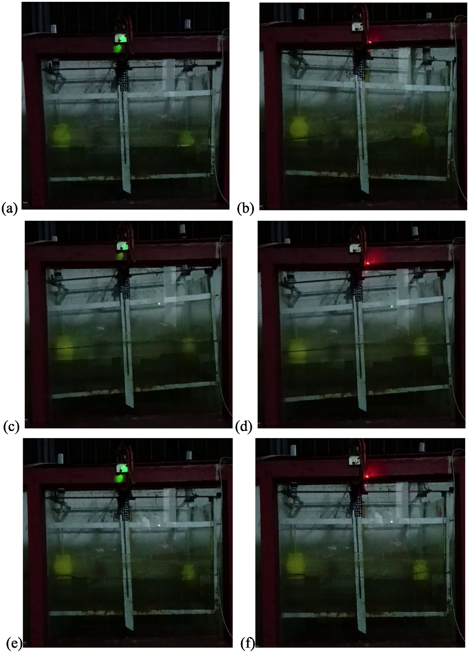
In Figure 20(a)–(f), as the incident wave frequency (excitation frequency) corresponds with the fundamental slosh natural frequency of the hybrid floating breakwater, there is impulsive slosh elevation that varies with time . As a result of the permanent magnet varying strongly across the copper coil windings, the magnetic flux rose, and a greater voltage is recorded in the volt multi-meter in a range that could light the Light Emitting Diode (LED) bulbs. As a result of the wave-induced excitation, the resonant response of the hybrid floating breakwater is adequate to illuminate two LED lamps alternately in each cycle of sloshing as shown in Figure 20(a)–(f). A series of experiments are carried out to encapsulate the effect of liquid fill depth in hybrid floating breakwater from 10% to 30% of breakwater’s height on the efficiency of hybrid structure as WEC. It is observed that for smaller depth of fill d ⩽ 10% the sloshing set the system in roll motion is limited to those excitation frequencies which are 10%–15% closer to the tank fundamental sloshing natural frequency , and the number of cycles of sloshing is not more than three, as well as there was a lack of completeness in each cycle. A full sloshing cycle due to roll motion is seen for a wide range of excitation frequency corresponding to time periods to 2.827 s as the depth of fill increased from 10% to 15%, 15% to 20%, and 20% to 25%. This was mostly due to the enhanced floating stability provided by the increased ballast weight, which resulted in an increase in the hybrid floating breakwater draft. However, increasing the draft by increasing the percentage of fill = 30% resulted in roll motion suppression due to the necessity of a larger magnitude of wave excitation that might roll the hybrid floating breakwater. This implies that the hybrid floating breakwater has a draft bandwidth beyond which the structure serves as a breakwater that is capable of attenuating the incoming progressive waves much lower than the set threshold values of wave reflection and transmission coefficients.
Electricity generation capture during the experiments for (a and b) s, (c and d) s, and (e and f) s respectively.
Conclusions
The present study investigates the hydrodynamic performance of a rectangular floating breakwater integrated with a wave energy converter under regular wave, restricted to (a) roll motion and (b) heave, surge, and roll motion. Considering the experimental investigation, the WEC capabilities and hydrodynamic coefficients (reflection and transmission coefficients) are estimated for a specific range of excitation frequencies , whereas for varying ranges of frequencies , the boundary element method is used with the assumption of modest sloshing in the tank of the hybrid floating breakwater using linear potential wave theory to estimate the hydrodynamic efficiency of the hybrid floating breakwater.
On comparing with the typical floating breakwater, the hybrid model increases wave attenuation damping, stabilizes the wave attenuation coefficient within and improves wave attenuation performance by 20%–35%.
Increasing width of the structure within , while maintaining the same draft will decrease the response amplitude operators of surge heave and roll motion, thereby resulting in an 10% reduction in wave transmission coefficient while the wave reflection coefficient increases by an average of 10%–15%.
The effect of increasing structural draft within , while maintaining the structure width on wave reflection and wave transmission coefficient is not significant for all the floating structure considered in the study in shallow water depth and part of the intermediate water depth region for . While the transmission coefficients reduces and wave reflection coefficients increase with increasing draft , in intermediate and deep-sea conditions. However, increasing structural draft will be beneficial for substantial reduction in wave transmission coefficients, but on the other side it ends up in raising the wave reflection coefficient in deep sea region, which may lead to formation of standing waves. Similar observation was recorded during experimental investigations.
The freely floating, coupled surge-heave and heave-roll coupled hybrid model not only exhibits better wave attenuation characteristics to satisfy the set criteria of both wave reflection and wave transmission coefficient less than 0.6, but also demonstrates approximately 50% of wave energy dissipation as cross-over points of wave reflection and wave transmission coefficient are much lower than 0.4.
The capture width ratio of a heaving hybrid floating structure increases with increase in structural width within in shallow water and in the intermediate water depth region for . Whereas increasing the structural draft has no influence on the capture width ratio in shallow water and part of the intermediate water depth region for . Further, the capture width ratio decreases with increase in draft of the structure for wave number .
The standing waves are generated on the seaward side of the hybrid floating breakwater when the excitation frequency is near to the fundamental sloshing natural frequency of the floating breakwater. This would easily induce equal-amplitude roll motion in both directions, resulting in sloshing events, which is an ideal condition for wave energy conversion.
The roll displacement of the floating breakwater is relatively less under short wave situations irrespective of the depth of fill . So, the wave transformation is within the desired range, the lack of rolling resulted in zero sloshing, which is undesirable for the proposed hybrid floating breakwater with WEC.
The hybrid floating breakwater attaints its floating stability for the depth of fill within 15% < d < 25% of partially filled liquid for which the propose of its design as a dual system as floating breakwater as well as WEC system is achieved for a wide range of excitation frequencies corresponding to time periods within . Otherwise, the hybrid floating breakwater serves as a barrier that is capable of attenuating the incoming progressive waves much lower than the set threshold values of wave reflection and transmission coefficient .
An impulsive sloshing dynamic of partially filled liquid as ballast is observed, when the wave excitation frequency is equal to half power band width for the range of frequencies, with the constraint that the hybrid floating breakwater is in state of dynamic float equilibrium. This optimal condition is met in this investigation when the depth of fill d = 25%.
Footnotes
Appendix
Acknowledgements
The authors express their gratitude to the Ministry of Education, Government of India, and the National Institute of Technology, Karnataka, Surathkal, for providing necessary facilities.
Declaration of conflicting interests
The author(s) declared no potential conflicts of interest with respect to the research, authorship, and/or publication of this article.
Funding
The author(s) disclosed receipt of the following financial support for the research, authorship, and/or publication of this article: DK acknowledges the partial support from Science and Engineering Research Board (SERB), India through research grant CRG/2018/004184 and Ministry of Ports, Shipping and Waterways, India through the research grant no. DW/01013(13)/2/2021-Development Wing.
ORCID iDs
Shivakumar B. Patil
Debabrata Karmakar
Data availability statement
The data that support the findings of this study are available from the corresponding author upon reasonable request.
References
1.
FalnesJ.A review of wave-energy extraction. Mar Struct2007; 20(4): 185–201.
2.
AstarizSIglesiasG.The economics of wave energy: a review. Renew Sustain Energ Rev2015; 45: 397–408.
3.
VicinanzaDContestabilePQuvang Harck NørgaardJ, et al. Innovative rubble mound breakwaters for overtopping wave energy conversion. Coast Eng2014; 88: 154–170.
4.
Pérez-CollazoCGreavesDIglesiasG.A review of combined wave and offshore wind energy. Renew Sustain Energ Rev2015; 42: 141–153.
5.
MustapaMAYaakobOBAhmedYM, et al. Wave energy device and breakwater integration: a review. Renew Sustain Energ Rev2017; 77: 43–58.
6.
ZhangHZhouBVogelC, et al. Hydrodynamic performance of a floating breakwater as an oscillating-buoy type wave energy converter. Appl Energy2020; 257: 113996.
7.
ClémentAMcCullenPFalcãoA, et al. Wave energy in Europe: current status and perspectives. Renew Sustain Energ Rev2002; 6(5): 405–431.
8.
HalesLZ.Floating breakwaters: state-of-the-art literature review. Technical Report, US Army Corps of Engineers, Coastal Engineering Research Center, Fort Belvoir, VA, USA, 1981.
9.
DrimerNAgnonYStiassnieM.A simplified analytical model for a floating breakwater in water of finite depth. Appl Ocean Res1992; 14(1): 33–41.
10.
LeeJF.On the heave radiation of a rectangular structure. Ocean Eng1995; 22(1): 19–34.
11.
SannasirajSASundarVSundaravadiveluR.Mooring forces and motion responses of pontoon-type floating breakwaters. Ocean Eng1998; 25(1): 27–48.
WengWKChouCR.Analysis of responses of floating dual pontoon structure. China Ocean Eng2007; 21(1): 91–104.
16.
ZhengSZhangY.Analysis for wave power capture capacity of two interconnected floats in regular waves. J Fluid Struct2017; 75: 158–173.
17.
JiQDongSLuoX, et al. Wave transformation over submerged breakwaters by the constrained interpolation profile method. Ocean Eng2017; 136: 294–303.
18.
LiangNKHuangJSLiCF.A study of spar buoy floating breakwater. Ocean Eng2004; 31(1): 43–60.
19.
ZhangXSMaSDuanWY.A new L type floating breakwater derived from vortex dissipation simulation. Ocean Eng2018; 164: 455–464.
20.
NikpourAHMoghimMNBadriMA.Experimental study of wave attenuation in trapezoidal floating breakwaters. China Ocean Eng2019; 33(1): 103–113.
21.
DengZWangLZhaoX, et al. Hydrodynamic performance of a T-shaped floating breakwater. Appl Ocean Res2019; 82: 325–336.
22.
GesrahaMR. Analysis of shaped floating breakwater in oblique waves: I. Impervious rigid wave boards. Appl Ocean Res2006; 28(5): 327–338.
23.
JiCYChenXCuiJ, et al. Experimental study of a new type of floating breakwater. Ocean Eng2015; 105: 295–303.
24.
CuiJLiuHDengX, et al. An experimental study on hydrodynamic performance of a box-floating breakwater in different terrains. J Mar Sci Technol2020; 25(4): 991–1009.
25.
TsengIFYouCSTsaiCC.Bragg reflections of oblique water waves by periodic surface-piercing and submerged breakwaters. J Mar Sci Eng2020; 8(7): 522.
26.
PatilSBKarmakarD.Hydrodynamic analysis of floating tunnel with submerged rubble mound breakwater. Ocean Eng2022; 264: 112460.
27.
NingDZhaoXChenL, et al. Hydrodynamic performance of an array of wave energy converters integrated with a pontoon-type breakwater. Energies2018; 11(3): 685.
28.
IsaacsonMPremasiriSYangG.Wave interactions with vertical slotted barrier. J Waterway Port Coast Ocean Eng1998; 124(3): 118–126.
29.
KoutandosEVKarambasTVKoutitasCG.Floating breakwater response to waves action using a Boussinesq model coupled with a 2DV elliptic solver. J Waterway Port Coast Ocean Eng2004; 130(5): 243–255.
30.
KoutandosEPrinosPGironellaX.FFS under regular and irregular wave forcing: reflection and transmission characteristics. Appl J Hydraulic Res2005; 43(2): 174–188.
WangYXDongHYLiuC.Experimental study of a pile-restrained floating breakwater constructed of pontoon and plates. China Ocean Eng2010; 24(1): 183–190.
33.
NingDZhaoXGötemanM, et al. Hydrodynamic performance of a pile-restrained WEC-type floating breakwater: an experimental study. Renew Energy2016; 95: 531–541.
34.
ZhaoXNingD.Experimental investigation of breakwater-type WEC composed of both stationary and floating pontoons. Energy2018; 155: 226–233.
35.
ZhaoXLNingDZLiangDF.Experimental investigation on hydrodynamic performance of a breakwater-integrated WEC system. Ocean Eng2019; 171: 25–32.
36.
ZhaoXNingDZhangC, et al. Hydrodynamic investigation of an oscillating buoy wave energy converter integrated into a pile-restrained floating breakwater. Energies2017; 10(5): 712.
37.
McIverPEvansDV.An approximate theory for the performance of a number of wave-energy devices set into a reflecting wall. Appl Ocean Res1988; 10(2): 58–65.
38.
ZhaoXDuXLiM, et al. Semi-analytical study on the hydrodynamic performance of an interconnected floating breakwater-WEC system in presence of the seawall. Appl Ocean Res2021; 109: 102555.
39.
CrowleySHPorterREvansDV.A submerged cylinder wave energy converter with internal sloshing power take off. Eur J Mech2014; 47: 108–123.
40.
TomNMMadhiFYeungRW.Power-to-load balancing for heaving asymmetric wave-energy converters with non-ideal power take-off. Renew Energy2019; 131: 1208–1225.
41.
ZhangCDingZChenL, et al. Sloshing dynamics of liquid tank with built-in buoys for wave energy harvesting. J Fluid Struct2022; 113: 103662.
42.
JeongHJKimSJKooW.Hydrodynamic analysis of a breakwater-integrated heaving-buoy-type wave energy converter with an optimal artificial damping scheme. Appl Sci2022; 12(7): 3401.
43.
FoxRWMcDonaldATPritchardPJ. Introduction to fluid mechanics. New York: John Wiley Sons, 2010.
44.
HughesSA.Physical models and laboratory techniques in coastal engineering. Singapore: World Scientific, 1993.
45.
IsaacsonM.Measurement of regular wave reflection. J Waterway Port Coast Ocean Eng1991; 117(6): 553–569.
46.
JungJHYoonHSLeeCY.Effect of natural frequency modes on sloshing phenomenon in a rectangular tank. Int J Nav Archit Ocean Eng2015; 7(3): 580–594.
47.
ChoIH.Transmission coefficients of a floating rectangular breakwater with porous side plates. Int J Nav Archit Ocean Eng2016; 8(1): 53–65.
48.
GodaY.Wave damping characteristics of longitudinal reef system. In: CliffordJE (ed.) Advances in coastal structures and breakwaters. Thomas Telford Publishing, 1996, pp.198–203.
49.
ElchahalGYounesRLafonP.The effects of reflection coefficient of the harbour sidewall on the performance of floating breakwaters. Ocean Eng2008; 35(11–12): 1102–1112.
50.
LiHBachynskiEE.Experimental and numerical investigation of nonlinear diffraction wave loads on a semi-submersible wind turbine. Renew Energy2021; 171: 709–727.
51.
PeñaEFerrerasJSanchez-TemblequeF.Experimental study on wave transmission coefficient, mooring lines and module connector forces with different designs of floating breakwaters. Ocean Eng2011; 38(10): 1150–1160.
52.
Molina-SanchezRCamposÁde AlfonsoM, et al. Assessing operability on berthed ships. Common approaches, present and future lines. J Mar Sci Eng2020; 8(4): 255.