In the present study, the fixed U-OWC integrated with Π-shaped breakwater is analysed considering three different bottom profiles (straight, inclined, and curved) of the interior chamber of the U-OWC. The hydrodynamic performance is assessed based on the theoretical maximum efficiency, radiation susceptance and conductance, reflection, transmission and dissipation coefficients and force coefficient on the top lip wall of U-OWC and front face of breakwater. The influence of geometric variations such as width of U-channel, draft of U-OWC, draft and width of breakwater and distance between the two structures on the hydrodynamic performance is analysed using Boundary Element Method (BEM). The study depicts that the presence of a wider U-channel width impairs the energy conversion efficiency of the U-OWC and increasing the draft of the U-OWC improves the efficiency of the device. Further, changing the bottom profile of the internal chamber of U-OWC changes the natural frequency of the device without hampering the efficiency. In addition, as the distance between the two structures is increased, transmission of waves decreases. The influence of wave force on the breakwater is noted to be maximum when the leading U-OWC structure has a curved bottom. The study on the variation of the bottom profile of the fixed U-OWC integrated with breakwater will be helpful in the design and analysis of efficient hybrid floating breakwater system.
In the recent decades, the need to produce and provide sustainable electricity has risen and amongst all the forms of renewable energy resources, the ocean energy is the most underutilised. Oceans around the world hold tremendous reserves of energy in the form of tides, currents, salinity gradients, waves and geothermal energy. Energy produced from the ocean can be through marine current power, tidal power, osmotic power, ocean thermal energy conversion and wave power. Out of all these available forms of ocean energy utilisation, the tidal power is the most widely recognised and ocean wave power is underutilised. The wave energy utilisation has seen significant research and improvements over the past decades and commercial viability is also being achieved. The wave energy utilisation remains greatly neglected due to high construction and maintenance costs combined with longevity and efficiency of the wave energy capturing devices. In order to harness the huge energy potential of ocean waves, the Wave Energy Converters (WECs) are employed and among various WEC devices, the Oscillating Water Column (OWC) device is most widely used due to its relatively easy maintenance (T.V.1). OWCs being one of the most extensively studied systems to harness wave energy, have reached partial commercial stage2 but like other WECs, even OWC has economical barriers. Thus, integrating WEC devices into existing marine structures will reduce the construction cost and will enhance the efficiency of WEC systems. A detailed review of OWC technologies, integration schemes and turbines are presented in Falcão and Henriques.3 In addition to the advantage of shared costs, integrated system of WEC and breakwater can reduce wave loads on the breakwater thus prolonging its life.4 OWCs can be easily integrated into breakwaters owing to the simplicity of their design. The first ever deployed prototype of a WEC integrated into a breakwater consists of five OWCs built into a caisson type breakwater at Sakata Port, Japan in 1989.5,6 In recent decade, the breakwater OWC integration is also deployed at the Mutriku port in Spain.7
The structure of a bottom fixed OWC primarily consists of a partially submerged front wall or ‘lip’ wall, an emerged back wall which together constitute a chamber between them and an air chamber fitted with a bi-directional turbine, typically a Wells turbine. The large opening below the water surface allows wave trains to move up and down inside the chamber compressing the air thereby driving the turbine and producing electrical energy. The OWC design can be modified in several ways to enhance its performance and one such way is to place an extra submerged barrier wall at a distance in front of the chamber giving rise to an extra channel between this barrier and the lip wall. The extra channel along with the internal chamber form an U-shaped duct and thus christening the device as U-OWC. Boccotti8 proved analytically that U-OWC device performs better than a conventional OWC device owing to its higher eigen period and air chamber pressure. A bottom fixed U-OWC has the added advantage of preventing sand intrusion and air inhalation into the chamber.9 The novel design by Boccotti8 was meant not only as WEC device, but also as a breakwater, which effectively being considered as an integrated WEC-breakwater system. An analytical study of the U-shaped OWC is carried out by Boccotti10 and using a small-scale field experiment the results obtained analytically were validated and reported by Boccotti et al.11 In a later study, Boccotti12 presented detailed design of the integrated system including power plant performance under different sea states, and design of chamber, duct, and exhaust tube of the device. The concept of U-OWC integrated into caisson breakwater was implemented into a full-scale plant REWEC3 and constructed at the Civitavecchia port in Italy.13
A novel concept of OWC breakwater integration namely WAVERUSH was introduced by Roberts and Shepherd14 which constituted rows of flexible tubes set within hollow concrete blocks laid on the front slope of a breakwater, generating energy by the displacement of the flexible tubes and the wave run up over the structure. The study claimed that the WAVERUSH device required less space than a conventional bottom fixed OWC while not compromising on the energy generation capabilities. Liu et al.15 reported the integration of caisson breakwater with OWC implemented in Qingdao port, China and its practical design with applied environmental conditions was studied. The bottom fixed OWCs perform primarily in shallow water depth regime of the waves as they are shore-attached devices and are exposed to phenomenon like air entrenchment and wave breaking. Moreover, shore connected devices are limited by the low energy density of nearshore waves. To tackle these challenges, deep sea offshore OWC devices have been devised. Additionally, with floating OWCs, it is possible to generate electricity with a frequency higher than that of the incident waves by using high speed turbines.16 A unique concept of a backward facing floating OWC was devised and tested by Yoshio Masuda called the Backward Bent Duct Buoy (BBDB).17 Since then, the BBDB concept has been studied by several researchers all around the globe.18–22 Another floating OWC device called the Mighty Whale, developed by Japan Marine Science and technology Centre, was deployed in the Gokasho Bay, Japan with a rated power of 100 KW.23,24 A range of OWC devices were made commercially available by an Australian company Oceanlinx and among various OWC devices deployed, one was shallow water shore connected OWC called the greenWAVE OWC, and deep water offshore floating devices in cluster of three joined in a space frame called blueWAVE OWC and a single OWC device capable of being connected to oil and gas platforms called ogWAVE OWC.25
The floating OWC can be fitted with a harbour in front of the entrance giving it a ‘L’ shape resulting in more focussed waves entering the device thereby increasing the frequency bandwidth of power generation. Rezanejad and Guedes Soares16 investigated the L-OWC using BEM approach and established that, through proper tuning of the device geometry, an extra resonance phenomenon could be enforced to improve the device’s energy conversion efficiency. Rezanejad et al.26 later performed experimental studies on L-OWC to determine the influence of wave characteristics and immersion depth of the device on its performance. Recently, the floating breakwater is used as an OWC device by removing the bottom of a conventional floating box breakwater, and hollowing out the interior and providing a nozzle at top of the resulting chamber for air to pass into a turbine. The novel idea of integrated OWC with breakwater was investigated by Koo27 and the study reported that the wave attenuation properties of this modified integrated system is better than a conventional floating box breakwater. Further, a moored floating caisson breakwater can be hollowed out with a submerged opening in the sea-side to function as an integrated system of breakwater OWC.28 A unique floating U-OWC integrated with a floating box breakwater is proposed and presented by Sundar et al.2 A pile restrained breakwater with an air chamber resembling a bottomless box is studied by He and Huang29 as an integrated system. The study reported that the wave attenuation performance of this integrated device is better than a simple pile restrained box breakwater due to the presence of an air chamber. On performing the detail literature review, the limited study on the variation of bottom profile of the U-OWC is noted for the integrated OWC-breakwater system.
In the present study, the investigation is carried out to analyse the performance fixed floating of U-OWC integrated with Π-breakwater using the Boundary Element Method (BEM). Three different bottom profiles of the internal chamber of the U-OWC such as straight, inclined, and curved bottom is considered and analysed. The performance of the integrated system is studied on varying the geometrical properties and hydrodynamic properties on analysing various hydrodynamic coefficients. In the case of the energy conversion performance of the U-OWC, the theoretical maximum efficiency along with non-dimensional radiation susceptance and radiation conductance coefficients are calculated. To assess the wave attenuation properties of the integrated WEC-breakwater system, the wave reflection, transmission, and dissipation coefficients are also investigated. Additionally, the wave force coefficients on the top lip wall of the U-OWC and the front face of the breakwater is evaluated. The influence of changing various geometrical properties of the two structures and the distance between the integrated system is studied on the performance of the OWC device. The highlight of the present study lies in the different bottom configurations of the inner chamber of the U-OWC integrated with Π-breakwater. The previous studies available in the literature have considered fixed floating OWC with and without integration of breakwater, but no study explores the effect of changing the bottom configuration of the OWC. Moreover, the wave transformation characteristics of an integrated system is not available in the published literature. The Π-shape breakwater has not been considered in previous studies as an integrated structure. Moreover, the present study considers the U-OWC to be attached at a distance from the Π-breakwater, which can be deemed as a retrofitting concept and help in creating integrated structures without much disturbance to an already existing breakwater or OWC structure.
Theoretical formulation
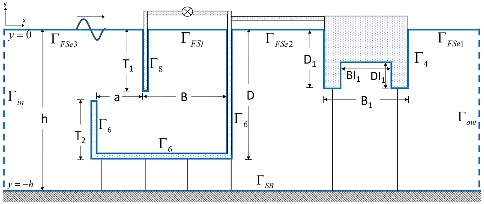
The schematic representation of the flat bottom U-OWC integrated with Π-breakwater is presented in Figure 1. A 3D coordinate system is considered for the theoretical analysis of U-OWC integrated with Π-breakwater. The xz-plane is considered horizontal, and y-axis, vertically downward negative. The front barrier wall of the U-OWC30 is located at and the U-OWC as well as the Π-breakwater are held in place with piles supporting them at the bottom. The height of the front barrier wall of U-OWC is denoted by , the top lip wall by and the draft is denoted by . The U-channel width is denoted by and the width of the internal chamber of the U-OWC is denoted as . So, the length of entire bottom base of the U-OWC is . The Wells turbine is fitted at top of the chamber, directly over the internal free surface. The Π-breakwater is kept at a distance “” behind the back wall of U-OWC and its width and draft are denoted by and respectively. The external free surface extends both ways from the back wall and from the top wall outside the chamber. Two auxiliary vertical boundaries are considered, at and at a distance “” behind the Π-breakwater.
Schematic representation of U-OWC device integrated with Π-breakwater.
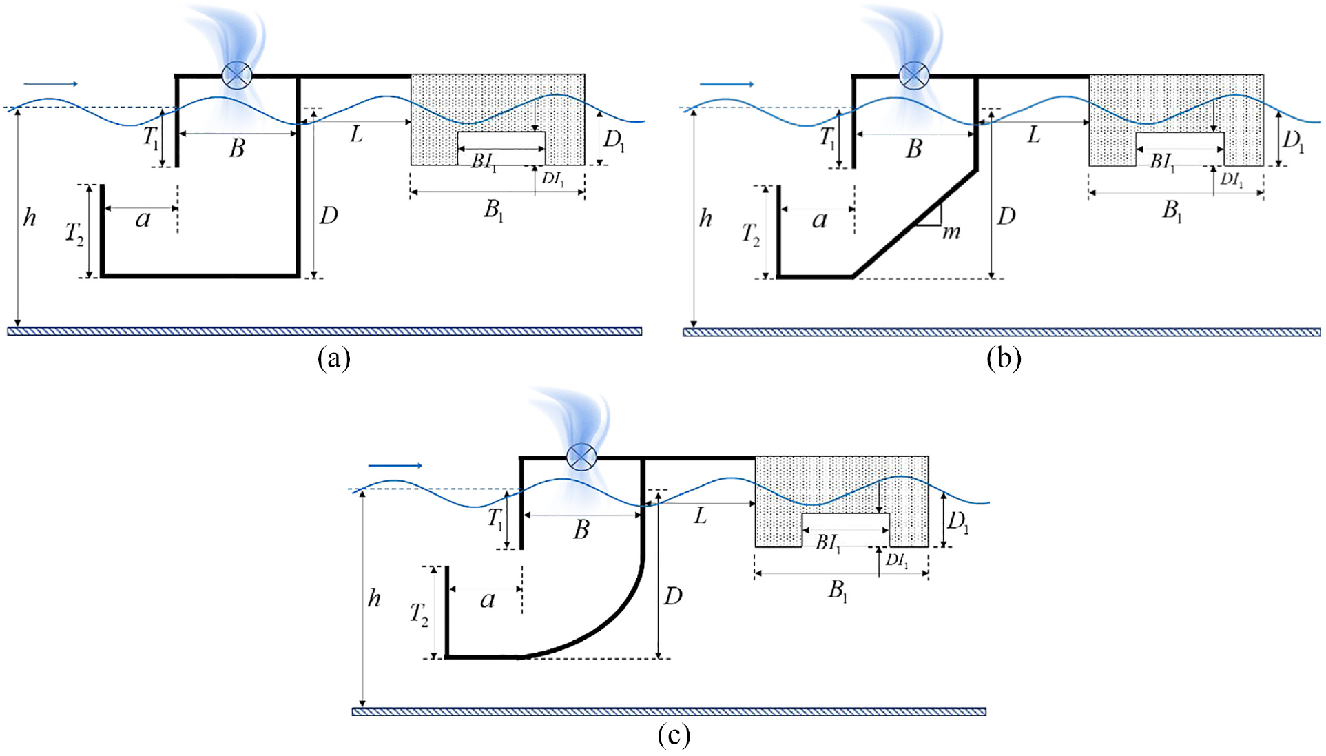
The bottom profile of the internal chamber consisting of straight bottom, inclined bottom and curved bottom of the U-OWC is shown in Figure 2(a) to (c). The slope of the inclined bottom profile of the U-OWC chamber is given by , and the curved bottom of the U-OWC chamber is an elliptical profile satisfying the equation , with the centre of the ellipse at the tip of the top lip wall. The fluid flow is assumed to be inviscid, incompressible and irrotational and thus the velocity potential for obliquely incident wave is of the form, , where . The velocity potential satisfies the Helmholtz equation in the fluid domain which can be expressed as
U-OWC device with (a) straight, (b) inclined, and (c) curved bottom profile integrated with a Π-breakwater kept at a distance.
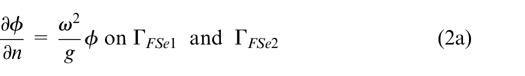
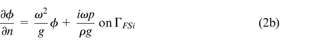
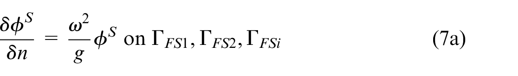
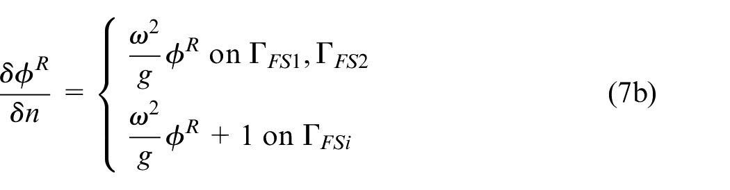
The free surface boundary condition inside OWC device and at the lee-side and sea-side of the integrated OWC-breakwater device is given by
where, g is the gravitational acceleration and represents normal derivative. The boundary condition on the rigid sea bed is given by
The boundary conditions on the impermeable surface of the U-OWC is given by
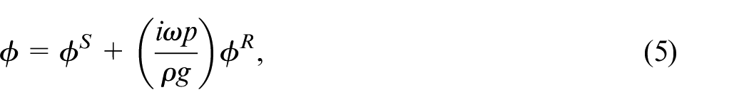
The total velocity potential is decomposed31 into two parts as follows
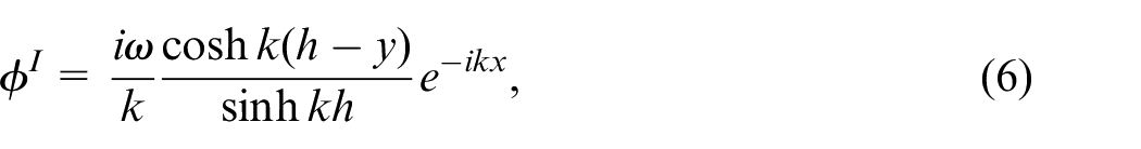
where, denotes the scattered velocity potential associated with the scattering of a plane incident wave in the absence of an imposed pressure on the internal free surface of the U-OWC chamber and denotes the radiated velocity potential, which is the solution to the radiation problem due to imposed pressure on the internal free surface. The scattered potential can be further decomposed into incident potential and diffracted potential . The incident potential can be obtained as
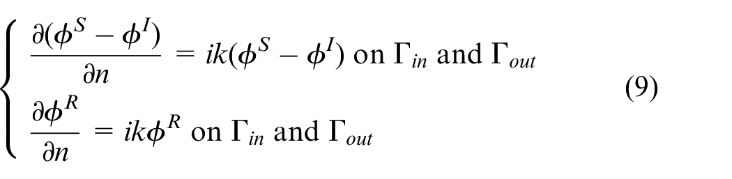
where represents the wave number, and is the positive real root of the dispersion relation . The scattered and radiated velocity potential and satisfy the boundary conditions (1)–(4) and equation (2a) is modified as
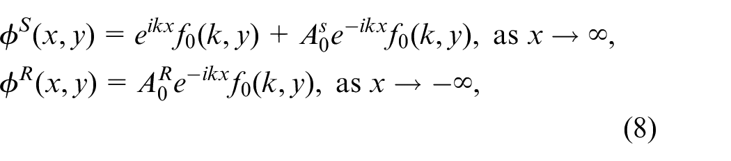
Finally, the far field Sommerfeld boundary condition is given by
where, and, are the amplitude of the scattered and radiated waves at respectively. As mentioned earlier, two auxiliary boundaries, and are considered at and behind the back wall of U-OWC respectively. These boundaries are sufficiently far away from the U-OWC device and hence, the far-field boundary condition (8) hold true. The far-field condition is modified as
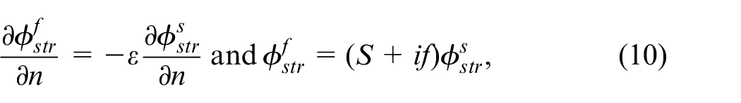
In the case of permeable structure, the porous boundary condition is expressed considering the continuity of pressure and mass flux between fluid and structure interface given by
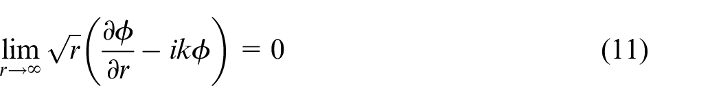
where, denotes velocity potential in water region and denotes the velocity potential in structure region, is the porosity of the structure, is the inertia coefficient of the porous breakwater and is the linearised friction coefficient.32,33 In the study, both the structures are considered as impermeable, hence the porosity is zero , and, friction and inertia coefficients tend to be infinite as they represent no flow condition through the structure. The far field Sommerfeld radiation condition is given by
where, . It is assumed that there is no loss of energy at input and output boundary region and hence the velocity potential can be expressed as
where is the incident wave potential, is the reflected wave potential and the is the transmitted wave potential.
Hydrodynamic parameters associated with U-OWC device
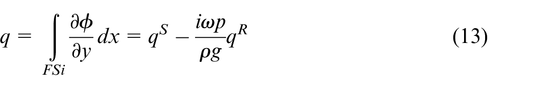
The explicit expressions for various hydrodynamic parameters associated with the performance of U-OWC device are discussed in the section. The time-harmonic volume flux34 across the internal free surface is given by
where and are the volume fluxes across the internal free surface for the scattering and radiation problems respectively. The volume flux for the radiation problem can be further decomposed into real and imaginary parts given by
where and are the radiation susceptance and radiation conductance parameters respectively,34 and are analogous to the added mass and the radiation damping coefficients in a rigid body system. The expressions for the radiation susceptance and radiation conductance are of the form
The radiation susceptance parameter denotes the energy that stays uncaptured by the system, and the radiation conductance parameter denotes the energy transferred into the system.35
It is assumed that the volume flux through the turbine is linearly proportional to the pressure drop across the internal free surface,31 So the volume flux is given by
where, is a real control parameter associated with the turbine characteristics. The mean rate of work done by the pressure force over one wave period is given by
Thus, for known values of and , the optimum value for can be obtained as
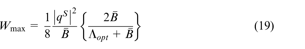
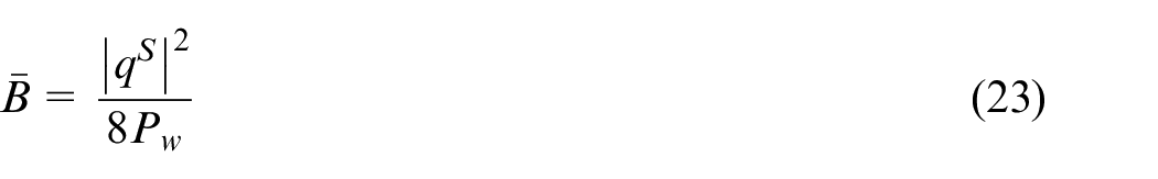
Hence, the maximum work done by the pressure force over one wave period is given by
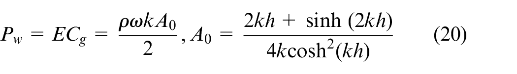
The available power over one wave period of a plane progressive of unit amplitude,36 is given by
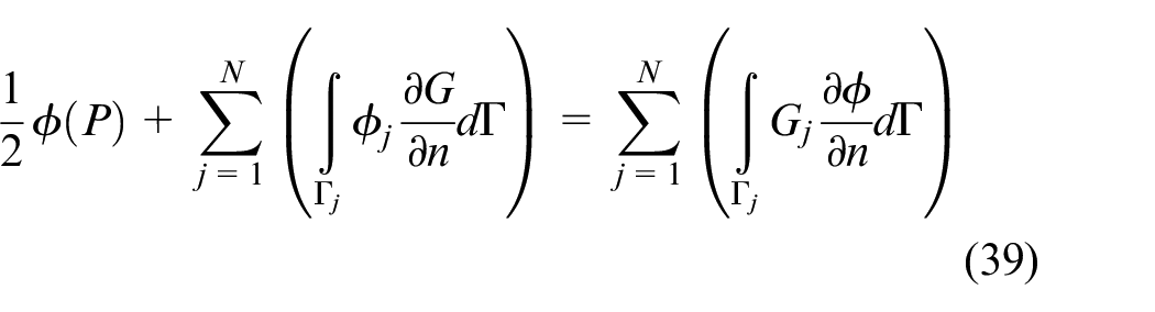
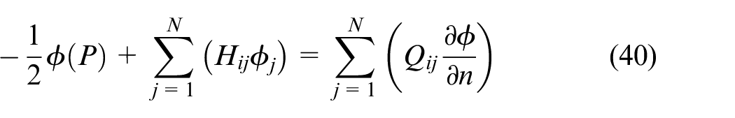
In order to obtain an explicit expression for the parameter , Green’s second identity is applied on and its complex conjugate over the whole domain bounded by . Summing up the contributions from all boundaries, we get
Similarly, the expression for scattered volume flux can be written as
Using equation (13), (14) and (15), the relation between and is obtained as
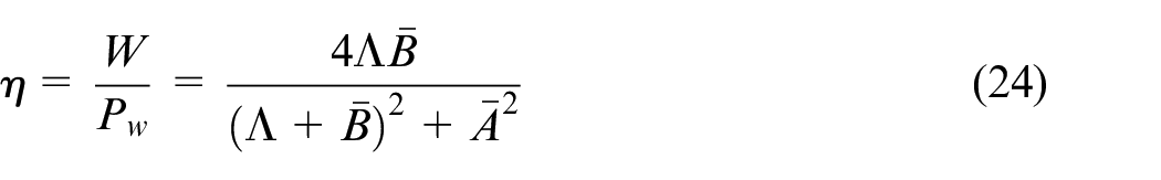
The efficiency of the U-OWC device is given by
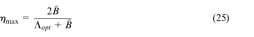
Further, the maximum efficiency is given by
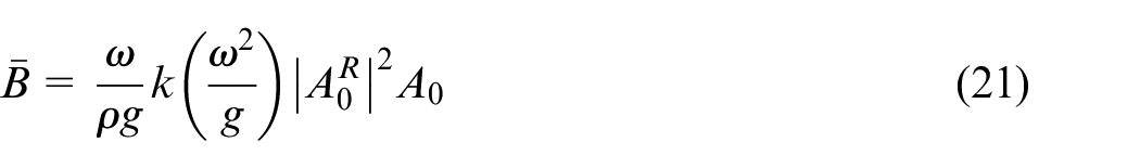
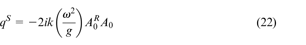
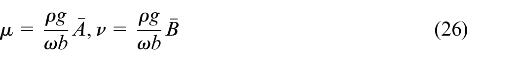
The dimensionless form of the parameters and ,34 is given by
Consequently, using equation (18) and (19), the dimensionless form of is of the form
Hence, the energy conversion efficiency is expected to be maximum when the wave energy transferred into the system (i.e. is maximum) and wave energy left unutilised (i.e. is minimum). The wave reflection and transmission coefficients are obtained as
where, is the incident wave amplitude, is the reflected wave amplitude and is the transmitted wave amplitude at the input and output boundaries. The relation between reflection, transmission, and dissipation coefficients37 is given by
The non-dimensional wave force coefficient is given by
where the wave force on the structure38 and is given by
Method of solution
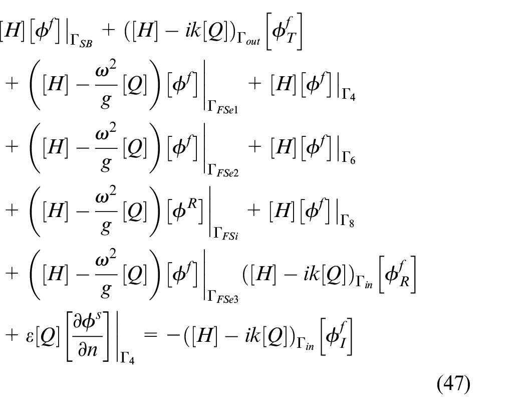
In this section, the solution method using Boundary Element Method (BEM) is described. The fundamental solution and Green’s second identity are the pre-requisites for BEM. To obtain the solution for the boundary value problem, the weighted residue and Green-Gauss theorem is applied to the Helmholtz equation as given in equation (1). The generalised form of boundary integral equation is expressed as
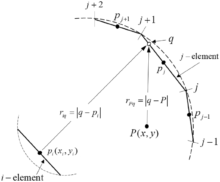
where is the unknown flow potential, is the derivative of the potential relative to normal unit vector on the boundary, is the fundamental solution to Helmholtz equation and denotes the computational domain boundary as shown in Figure 3 for an arbitrary region surrounded by boundary which is further decomposed by constant elements. These constant elements form a new boundary which is an approximation of the original boundary . equation (32) relates the value of flow potential at a fixed point to each arbitrary point on the entire boundary.
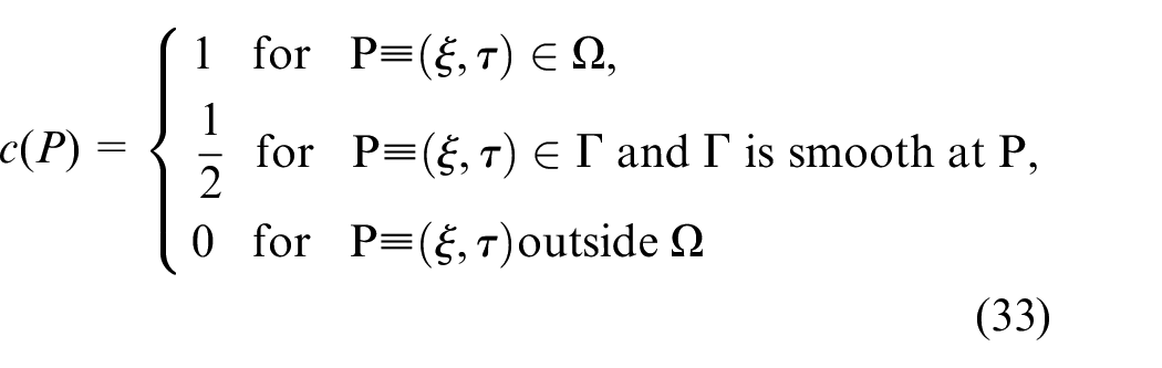
The free term coefficient depends on the shape of the boundary is given by
Since the present method considers constant boundary elements with smooth boundary, so the free term coefficient becomes
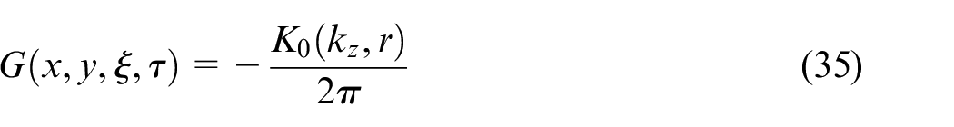
The fundamental solution, is the free space Green’s function, , is expressed as a function of modified zeroth-order Bessel function of second kind , given by
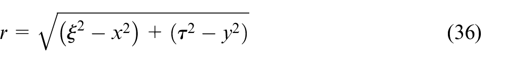
where is the distance between the field point and the source point given by
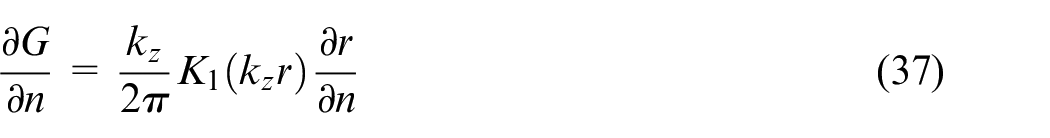
The normal derivative of Green’s function is given by
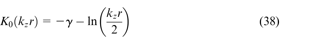
where, is the modified first-order Bessel function of the second kind. In the case of singularity, , shows asymptotic behaviour and is given by
where, is called the Euler’s constant. The boundary is assumed to be divided into ‘’ constant elements. The value of and are assumed to be constant over each element and assumed to be equal to the value at the mid-element node. Further, the equation (32) is discretised into ‘’ constant boundary elements before applying the boundary conditions, and is expressed as
where, is the boundary in the jth element. Now, considering , where is the Kronecker delta which is defined as for and for , and the equation (39) can be rewritten as
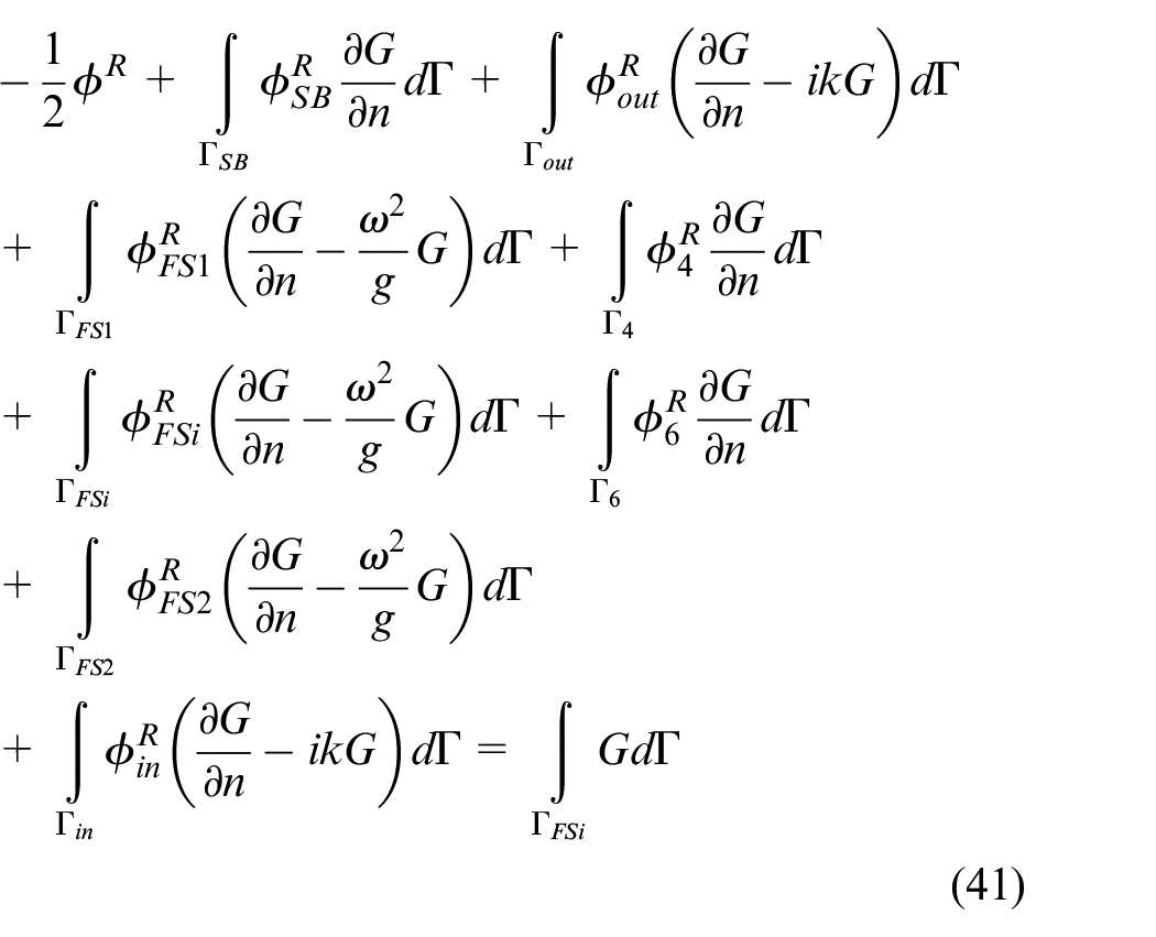
The line integrals and represent the influence functions between element at which the fundamental solution is applied and any other element under consideration. In order to obtain the efficiency and radiation parameters pertaining to the OWC, the boundary conditions given in equation (2), (4), (5), (8) and (10) are applied on equation (39), and the integral equation for radiated potential is derived as
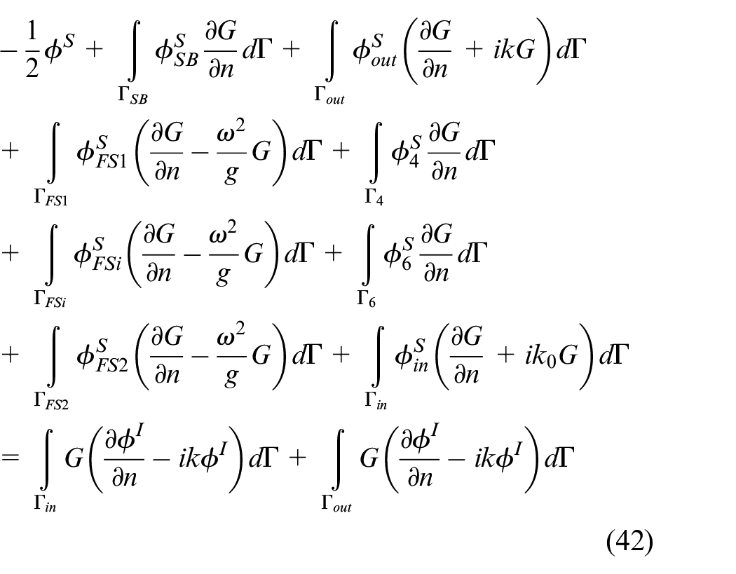
Similarly, using boundary conditions on equation (39), the integral equation for the scattered potential is derived as
The integral equation as in equation (41) and (42) can be discretised and expressed as
The values of and are calculated using a standard Gaussian quadrature.39 Finally, using the method of point collocation, in which the source point runs over each boundary element, equation (43) and (44) give the following matrix equations given by
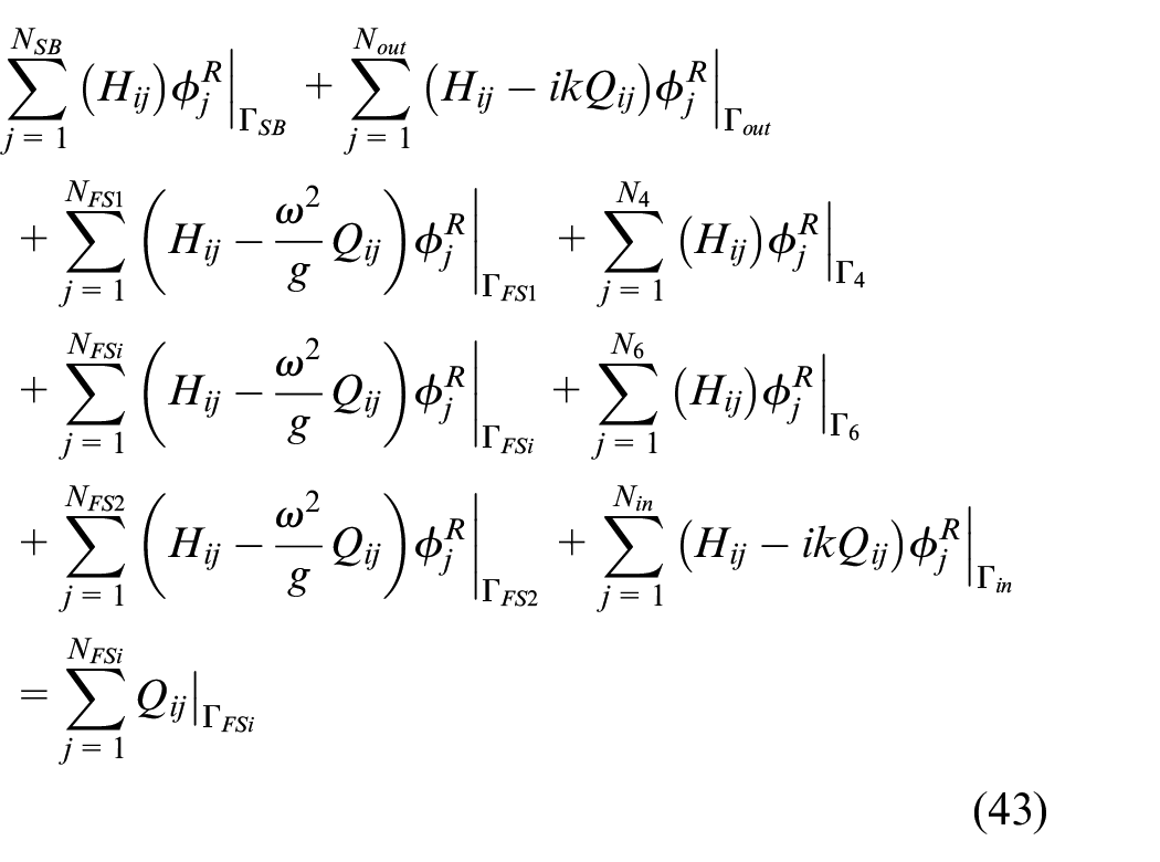
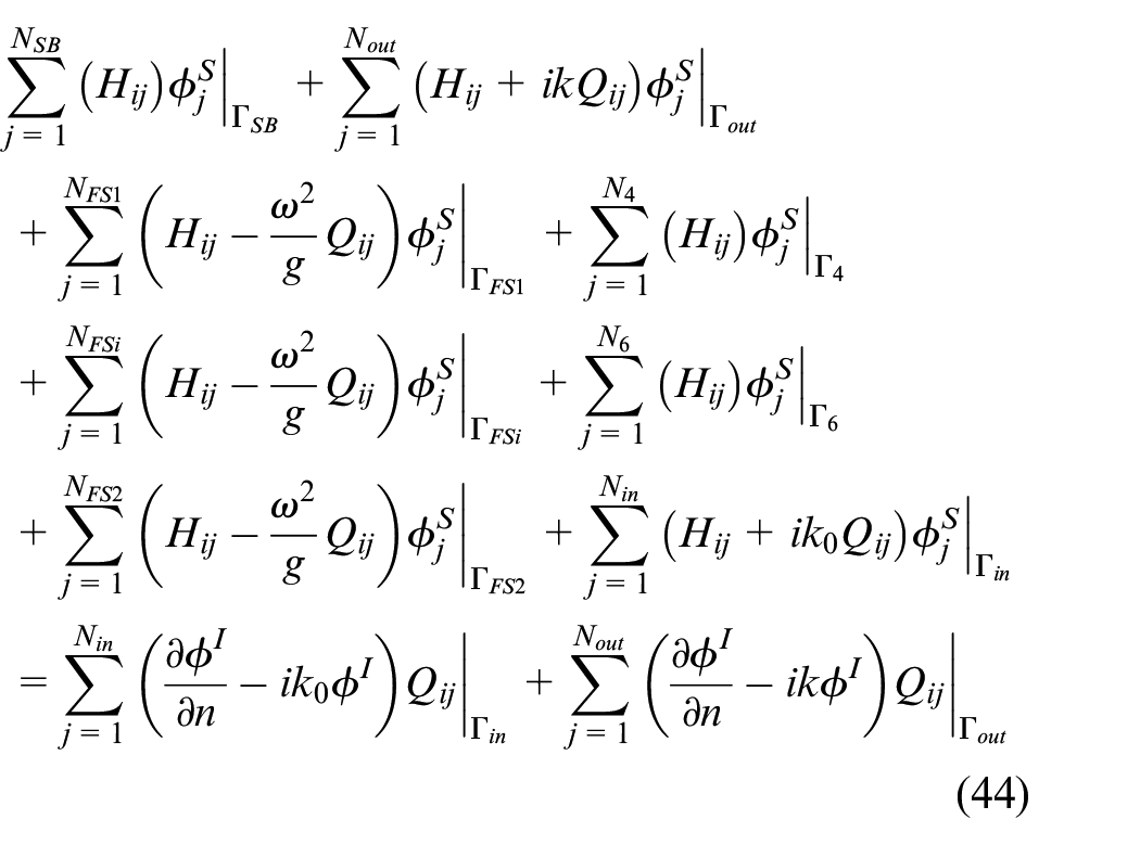
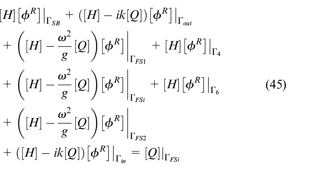
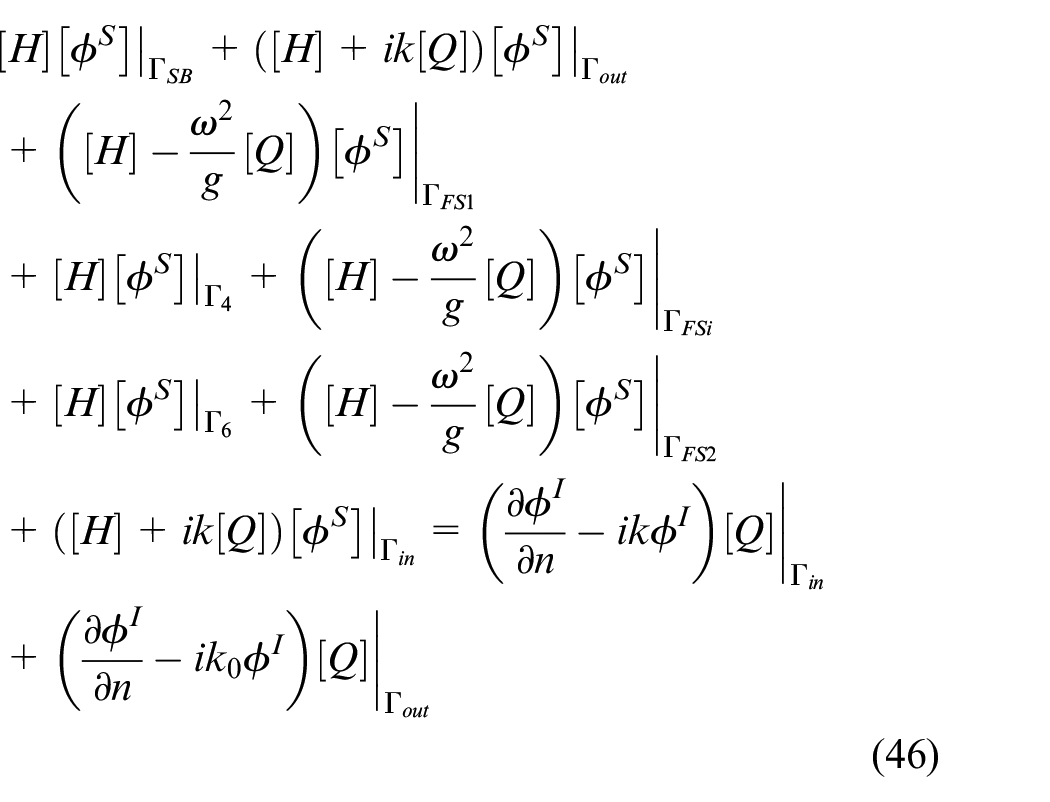
Next, to obtain the reflection, transmission and dissipation coefficients, the boundary conditions given in equation (11), (12), (13), (14), (16) and (17) are applied on equation (42), and the integral equation to solve for reflected and transmitted potential in the fluid domain is obtained and presented in matrix form as
The potentials indicated by , , and are the unknown radiated, scattered, transmitted and reflected velocity potentials to be calculated. In equation (45–47), correspond to the boundaries of the far-field, seabed, external and internal free water surfaces, and the floating structure boundaries respectively. After obtaining the unknown potentials at the nodes of the discretised boundary elements, the hydrodynamic performance parameters of the device are obtained.
Numerical results and discussion
In this section, the numerical results pertaining to the hydrodynamic performance of fixed U-OWC of different bottom profiles integrated with Π-breakwater are discussed in detail. The validation of the present numerical method is provided by comparing results obtained from the present BEM model to results published in the literature. Thereafter, in the subsequent sub-sections, the results associated with change in various geometrical and structural properties of the integrated system are discussed.
Validation of numerical model
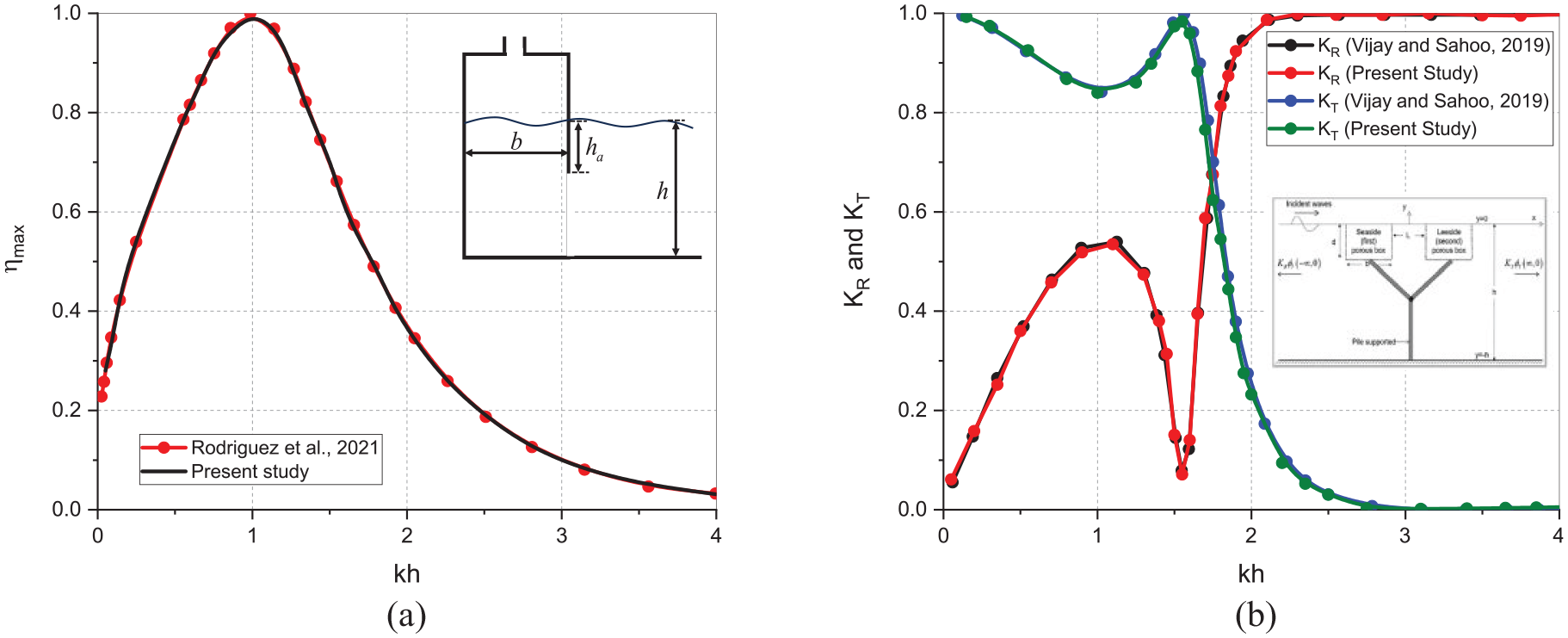
The BEM model developed in the present study is validated with the results of Rodriguez et al. (2021) for the case of a bottom fixed OWC (Figure 4(a)). The comparative study for the theoretical efficiency is performed considering the geometrical parameters , and as in Medina Rodríguez et al.40 The theoretical maximum efficiency, (Figure 4(a)) obtained by Medina Rodríguez et al.40 and using the present BEM approach exactly match throughout the wavenumbers within, . Miniscule difference in results maybe observed in a few places owing to the different types of elements considered in the boundary value problem. The present study employs constant elements, whereas Medina Rodríguez et al.40 considered three-nodded quadratic elements.
Validation of BEM model with (a) Medina Rodríguez et al.40 for , and (b) Vijay and Sahoo41 for and .
Further, in Figure 4(b), the present BEM model is validated with the results of Vijay and Sahoo41 for the wave reflection and transmission coefficients. The structure considered is a pair of fixed floating identical impermeable boxes. The geometry considered is the same as in Vijay and Sahoo41 considering , and . It is observed that the results of and from both the methods match exactly as the BEM model and the element type used are the same.
Convergence study of the BEM model
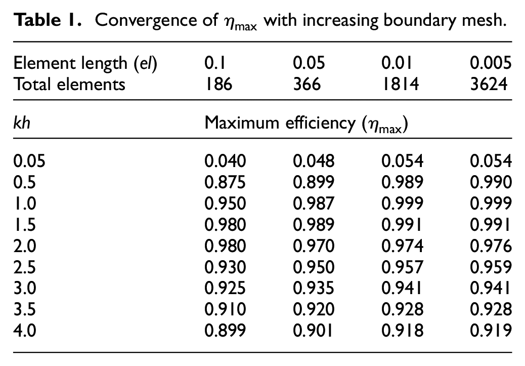
The boundary mesh is an essential component of any boundary value problem and the fineness of the mesh dictates the precision of boundary value calculations. In the BEM approach, the boundary is made up of several boundary elements and the length of the elements determines the number of elements in the boundary and ultimately defines the fineness of the mesh. The element length is fixed based on the convergence of the hydrodynamic parameter. In the present study, convergence of the theoretical maximum efficiency, is performed for a fixed floating straight bottom U-OWC integrated with Π-breakwater, as represented in Figure 1. The structural parameters of the integrated breakwater and OWC system are considered as , , , , , , , , and . The convergence of versus non-dimensional wavenumber for respective element length is presented in Table 1.
Convergence of with increasing boundary mesh.
Element length ()
0.1
0.05
0.01
0.005
Total elements
186
366
1814
3624
Maximum efficiency ()
0.05
0.040
0.048
0.054
0.054
0.5
0.875
0.899
0.989
0.990
1.0
0.950
0.987
0.999
0.999
1.5
0.980
0.989
0.991
0.991
2.0
0.980
0.970
0.974
0.976
2.5
0.930
0.950
0.957
0.959
3.0
0.925
0.935
0.941
0.941
3.5
0.910
0.920
0.928
0.928
4.0
0.899
0.901
0.918
0.919
The fixed floating U-OWC integrated with Π-breakwater is discretised considering progressively smaller element lengths to determine the element length at which converges. The element lengths considered are 0.1, 0.05, 0.01 and 0.005. The total number of elements increases as the boundary mesh gets finer and as the element length decreases. The values of are truncated at three decimal places to check for convergence. It is observed that for , the value of converges at the third decimal place for element lengths 0.01 and 0.005. At all other wavenumbers, the varies minutely only in the third decimal place for element lengths 0.01 and 0.005. Thus form the convergence study, it can be concluded that the converges at element length 0.01 for most of the wavenumbers thereby making as the suitable boundary element length for all further investigations in the study.
Efficiency, radiation susceptance and radiation conductance
In the present section, the hydrodynamic performance, in terms of maximum theoretical efficiency , non-dimensional radiation susceptance and radiation conductance of the U-OWC integrated with Π-breakwater is presented. The variations in the relative U-channel width and relative draft of U-OWC for straight, inclined, and curved bottom profiles are analysed in detail. The geometrical parameters that are kept fixed unless or otherwise mentioned are , , , and for the U-OWC, for the Π-breakwater , , , and the distance between the U-OWC and the Π-breakwater .
Straight bottom U-OWC with π-breakwater
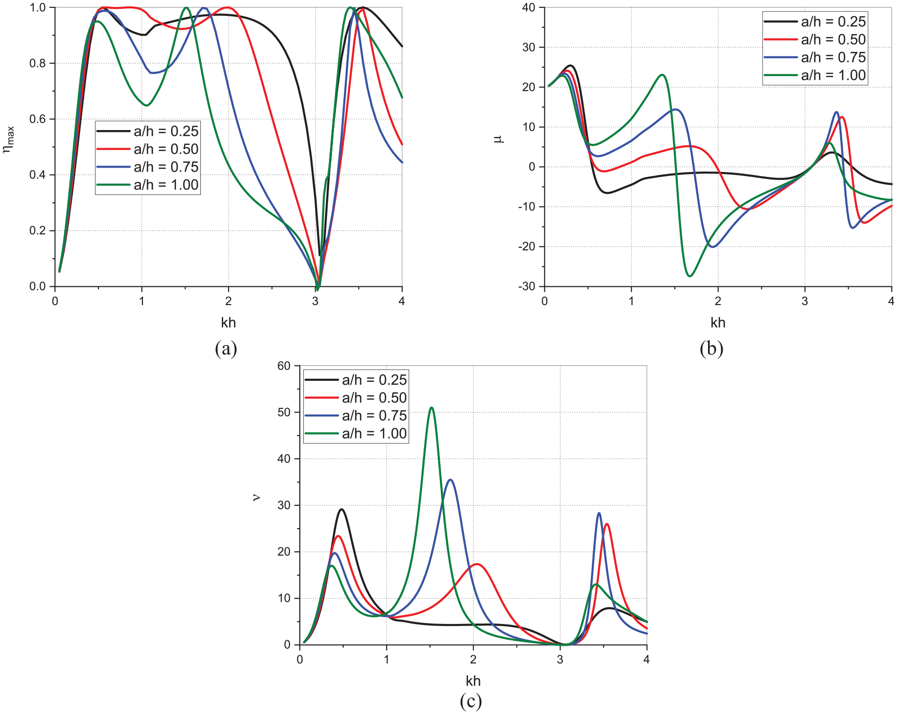
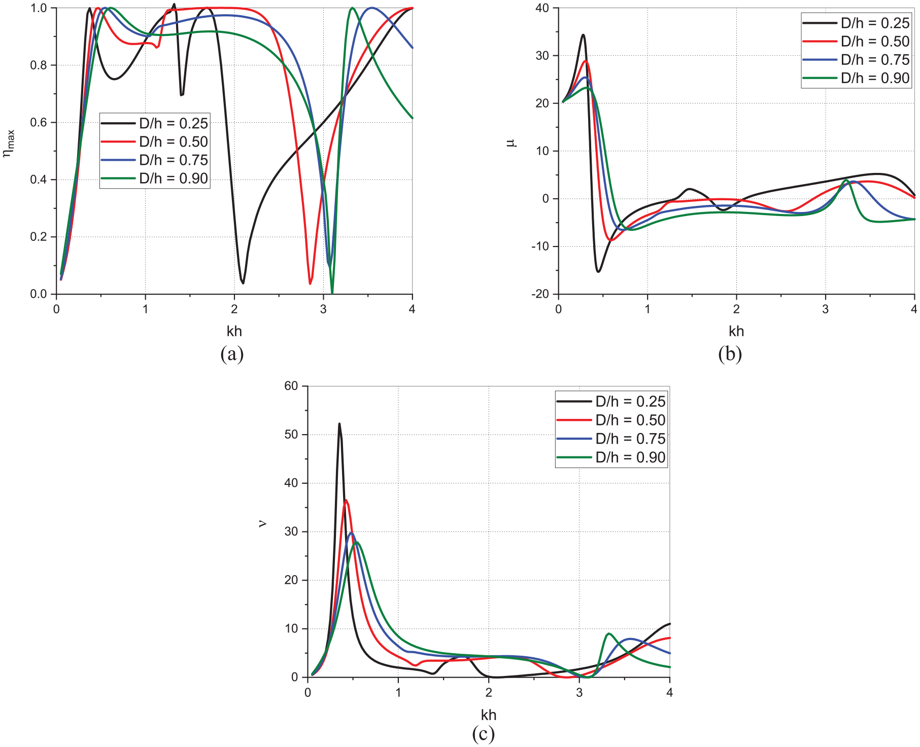
The performance of straight bottom U-OWC integrated with Π-breakwater is studied in terms of the energy conversion efficiency, and the non-dimensional radiation susceptance and conductance coefficients. The relative ‘U’ channel width and the relative draft of the straight bottom U-OWC are varied to study their effects on the parameters. The performance parameters are studied as a function of non-dimensional wavenumber . In Figure 5(a) to (c), the effect of varying the relative U-channel width of straight bottom U-OWC on the theoretical maximum efficiency , non-dimensional radiation susceptance and radiation conductance is studied. It is observed that the (Figure 5(a)) for all variations in approaches maximum value of in the intermediate water depth of and , and in the deep water region of . The radiation susceptance (Figure 5(b)), which indicates uncaptured energy, crosses over zero value corresponding to or stays very near to zero when which signifies that the unutilised energy is less. The radiation conductance (Figure 5(c)) which is responsible for the energy being transferred into the system has maxima in the three wavenumber ranges corresponding to the maxima of the . The approaches zero for all variations in within the wavenumber range which can be termed as the critical wavenumber range. The widest range of wavenumbers wherein the is one or near to one is the intermediate water depth of , and the capture width reduces as the is increased from 0.25 to 1.0. The study suggests that the wider U-channel width causes wave energy to get dissipated in the channel and does not get transferred into the internal chamber resulting in a poorer performance.
Variation of (a) , (b) and (c) versus for different in the case of straight bottom U-OWC with Π-breakwater.
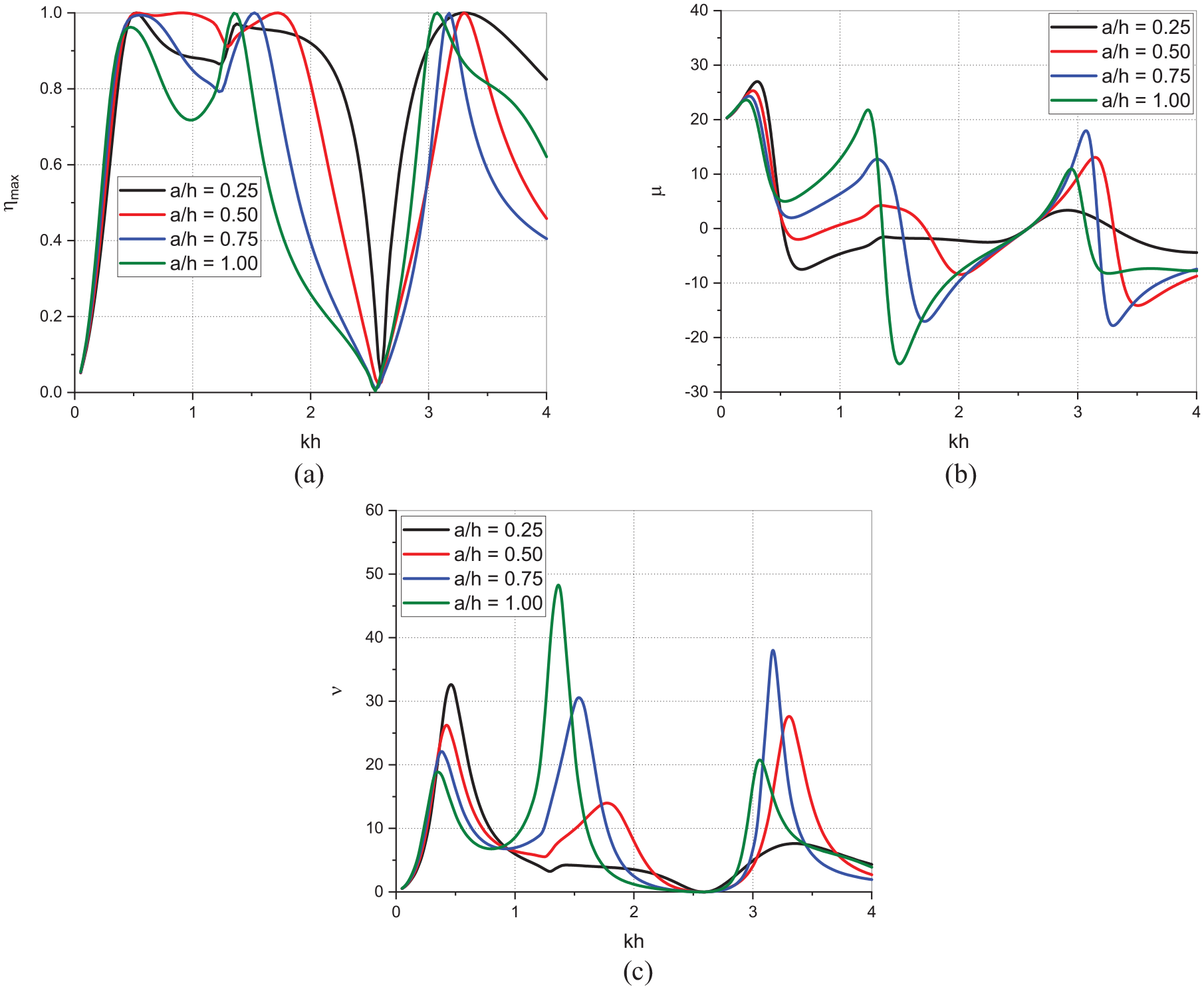
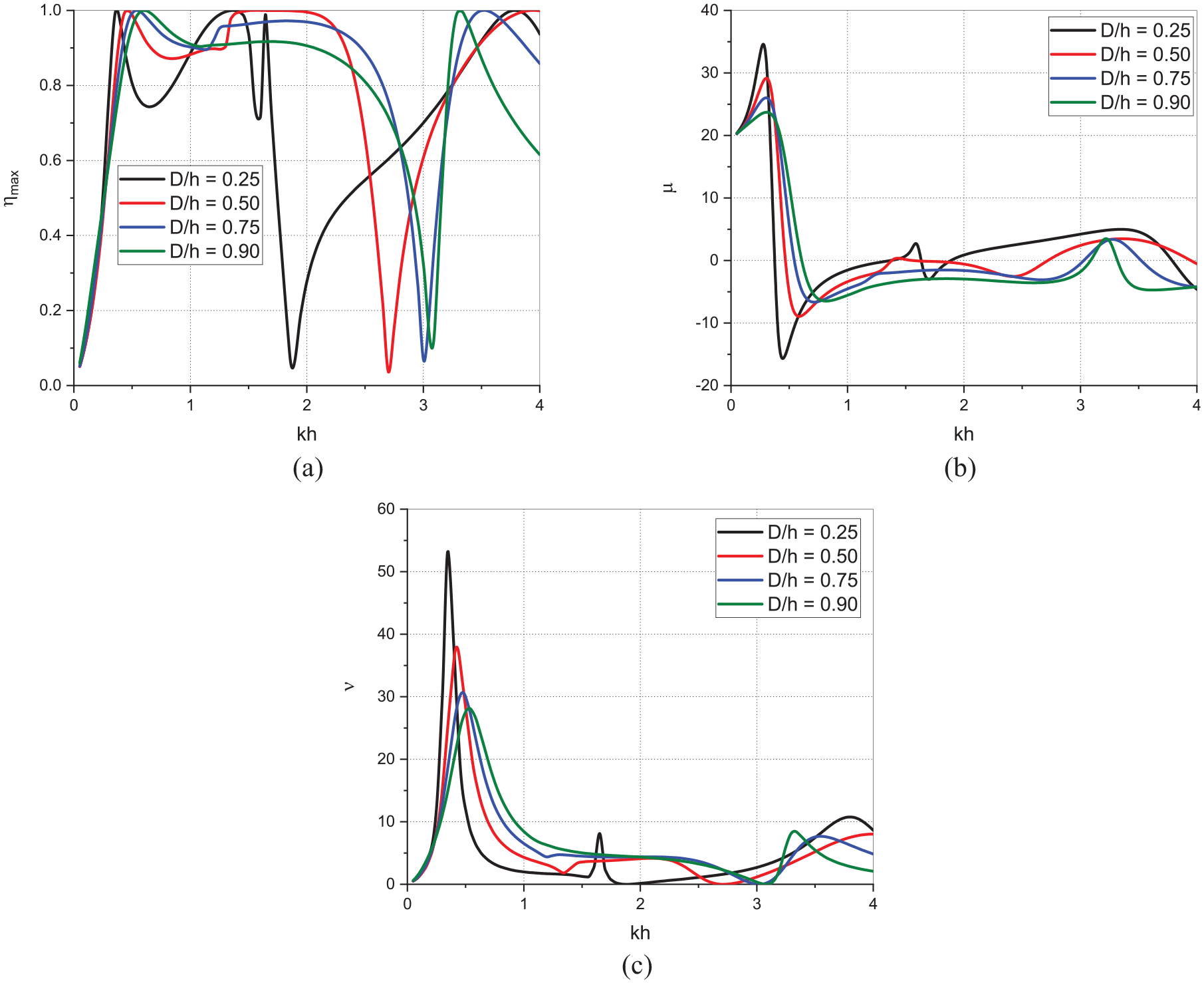
The effect of varying the relative draft of the straight bottom U-OWC on the , and is studied in Figure 6(a) to (c). The (Figure 6(a)) for all variations in approaches maximum value of in the shallow water depth of intermediate water depth of , and in the deep water region of . approaches maximum value for the widest range of wavenumbers in the intermediate water depth of , and has closest to one within . Thereafter, the is noted to be decreasing by around 3% and 6% for increasing relative draft within . The observation suggests that on increasing the draft and thereby the volume of the oscillating column of water does not necessarily lead to increased efficiency. A larger volume of water column might have hindrance to oscillatory movement due to its increased weight hence leading to poorer performance. On varying the relative draft, the range of critical wavenumber also changes wherein the approaches zero indicating a change in the resonant frequency of the device. The radiation susceptance (Figure 6(b)) is observed to be crossing zero at points where the has maximum value. Moreover, the radiation conductance (Figure 6(c)) has maxima in the shallow water depth of and thereafter stays at lower values of for wavenumbers . This suggest that enough energy is not transferred into the system, and the energy left unutilised is also very low as indicated by the near zero values of , hence being adequate for reaching maximum performance. The for configuration has lowest trough values and takes a wider range of to reach maximum value after . Since most of the wave energy is concentrated near the surface of the sea and the bottom wall close to the surface (due to shorter draft) dissipates most of the wave energy instead of letting it inside the chamber of the U-OWC, so the integrated system results in poor performance.
Variation of (a) , (b) and (c) versus for different in the case of straight bottom U-OWC with Π-breakwater.
Inclined bottom U-OWC with π-breakwater
On inclining the bottom of the internal chamber of the U-OWC facilitate smoother movement of the water column resulting in amplified oscillations leading to comparable or even better energy conversion efficiency than the straight bottom U-OWC. Thus, the performance of the inclined bottom U-OWC integrated with Π-breakwater is analysed in terms of the theoretical maximum efficiency, non-dimensional radiation susceptance and conductance parameters to study the effect on varying the relative U-channel width and draft of U-OWC.
In Figure 7(a) to (c), the effect of varying the relative ‘U’ channel width is studied on the energy conversion efficiency, radiation susceptance and radiation conductance of the integrated U-OWC with Π-breakwater. The (Figure 7(a)) is observed to have maxima in the intermediate water depth of and in the deep water region of and minima within . As compared to straight bottom U-OWC (Figure 5(a)), the inclined bottom has a reduced width of wavenumber where the has maximum value and the resonant frequency of the device is altered as indicated by the position of zero efficiency. The overall performance of the inclined bottom U-OWC might be considered similar to that of straight bottom U-OWC, but as the is varied within , the width of wavenumbers where maxima of occurs is observed to be reduced in the range , suggesting that a wider ‘U’ channel leads to dissipation of wave energy instead of being converted to useful energy by the U-OWC. This inference can also be verified by observing the radiation susceptance (Figure 7(b)) which stays close to zero for and increases for any increase in . The radiation conductance (Figure 7(c)) has maxima at wavenumbers corresponding to maxima of for variations in within but stays at low values for . Since the energy left unutilised is almost zero, so the lower values of are sufficient for high energy conversion efficiency.
Variation of (a) , (b) and (c) versus for different in the case of inclined bottom U-OWC with Π-breakwater.
In Figure 8(a) to (c), the effect of varying relative draft of the inclined bottom U-OWC is studied on the energy conversion efficiency, radiation susceptance and radiation conductance. The maxima of (Figure 8(a)) occurs in the shallow water depth of , intermediate depth of , as well as in the deep wate region of . approaches zero at different wavenumbers for the variations in , indicating that varying the draft of an inclined bottom U-OWC changes the resonant frequency of the structure to a greater extent than that of a straight bottom U-OWC. The performance is noted low for the smallest draft , and the performance gets better as the draft increases. In the wavenumber range , for is the highest, but for a very narrow width of wavenumbers, whereas for is lower by around 5% but for a wider range of wavenumbers. The radiation susceptance (Figure 8(b)) for all variations in is close to zero for most of the wavenumbers, but the radiation conductance (Figure 8(c)) is also very low. The study suggest that a moderate draft can give good performance but an inclined bottom U-OWC does not necessarily improve the integrated U-OWC with Π-breakwater energy conversion efficiency.
Variation of (a) , (b) and (c) versus for different in the case of inclined bottom U-OWC with Π-breakwater.
Curved bottom U-OWC with Π -breakwater
The U-OWC is modified to have a curved bottom where the volume of the structure is less as compared to a straight bottom U-OWC and due to the curved bottom, it is expected to have a comparable energy conversion efficiency. Thus, in the present section the curved bottom U-OWC integrated with Π-breakwater is studied in terms of energy conversion efficiency, radiation susceptance and conductance parameters while varying the relative U-channel width and the relative draft of U-OWC.
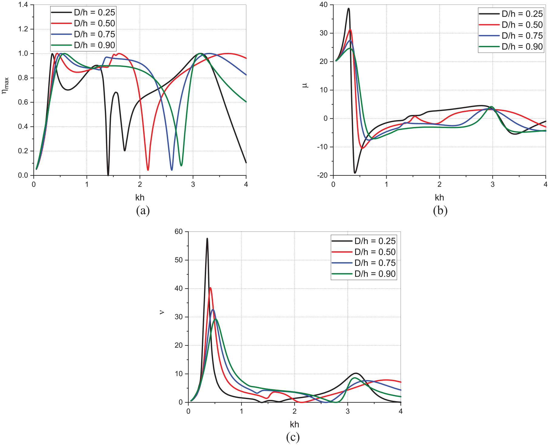
In Figure 9(a) to (c), the effect of varying the relative U-channel width of the curved bottom U-OWC is studied on the efficiency, radiation susceptance and radiation conductance. The behaviour of the (Figure 9(a)) for all values of relative U-channel width of curved bottom U-OWC is almost same as observed for straight bottom U-OWC (Figure 5(a)). On transforming the internal chamber’s bottom from straight to curved while varying the relative U-channel width does not change the natural frequency and the energy conversion efficiency of the U-OWC device. So, the pattern of is noted to be same for varying in the case of curved bottom. The energy unutilised and the energy transferred into the system are noted to be similar for both bottom profiles as can be observed on comparing the radiation susceptance (Figures 5(b) and 9(b)) and radiation conductance (Figures 5(c) and 9(c)) for the case of straight bottom and curved bottom. The curved bottom profile of U-OWC has a lesser volume than a straight bottom profile, but offers a smoother path for the waves to oscillate in the chamber which amplifies the rise and fall of the water column leading to comparable efficiencies.
Variation of (a) , (b) and (c) versus for different in the case of curved bottom U-OWC with Π-breakwater.
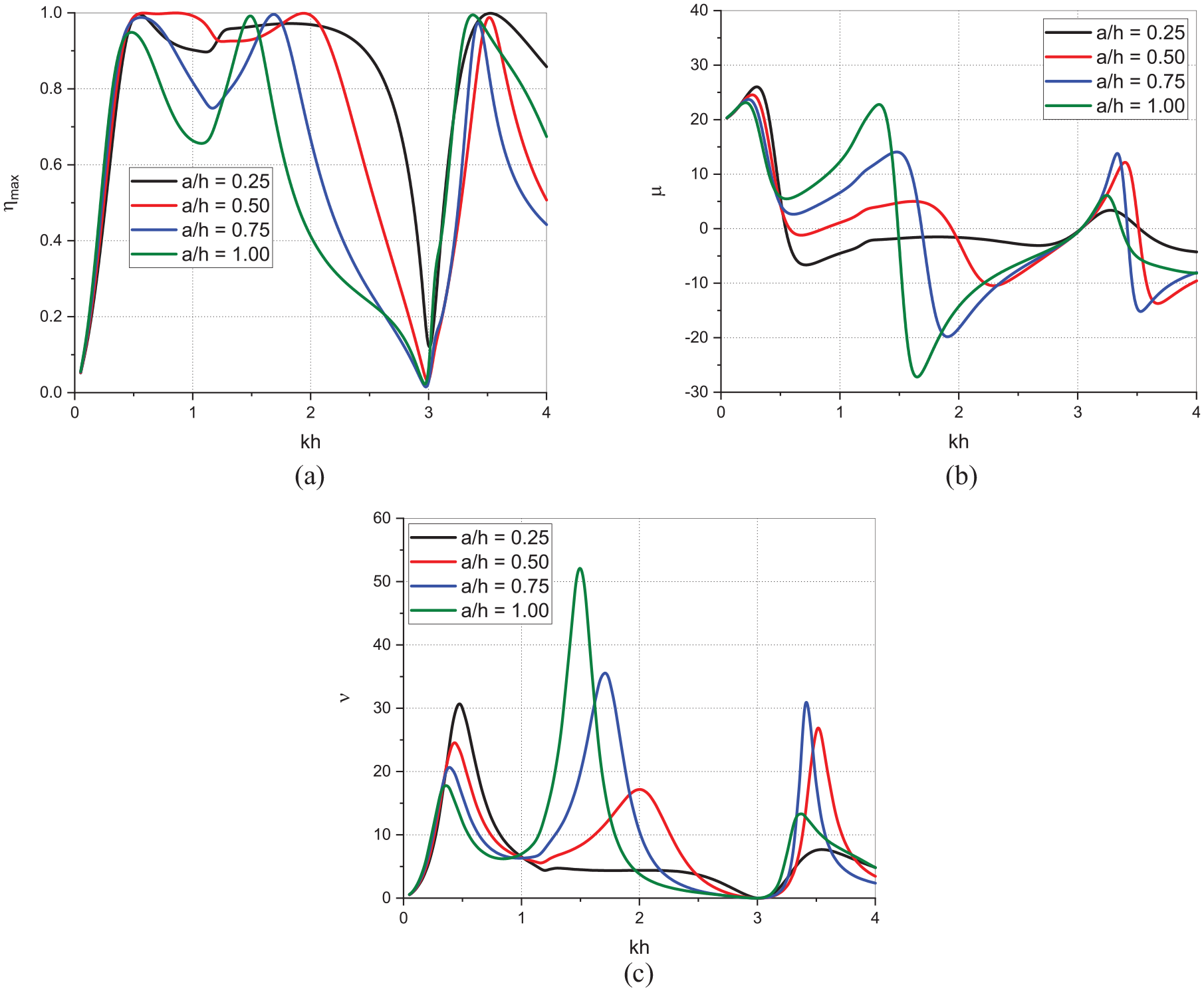
In Figure 10(a) to (c), the effect of varying relative draft of the curved bottom U-OWC is analysed for the efficiency, radiation susceptance and radiation conductance. The natural frequencies for various relative depth of the curved bottom U-OWC are noted to have minimal variation but noticeable variation as compared to straight bottom U-OWC. The local minima in within the wavenumber range for various relative draft is noted to shift towards lower in the case of curved bottom U-OWC. A similar shift is also observed in case of radiation susceptance (Figure 10(b)) and radiation conductance (Figure 10(c)) when compared with straight bottom U-OWC. In the case of same draft, the natural frequencies of curved bottom and straight bottom U-OWC do not vary significantly, but noticeable changes are observed in their performances. Thus, the study noted that a very short draft leads to poor energy conversion efficiency and increasing the draft till a moderate value gives maximum performance.
Variation of (a) , (b) and (c) versus for different in the case of curved bottom U-OWC with Π-breakwater.
Reflection, transmission and dissipation coefficients
The wave reflection, transmission and dissipation coefficients are essential to be studied to gauge the performance of a breakwater structure. The hybrid system of a U-OWC integrated with a Π-breakwater is analysed for different structural variations to study their effect on , and . The hydrodynamic parameters are studied as a function of the non-dimensional wavenumber considering angle of incidence and as a function of for . The structural parameters of the integrated system is considered to be , , , , , , , , and , unless otherwise specified.
Straight bottom U-OWC with π-breakwater
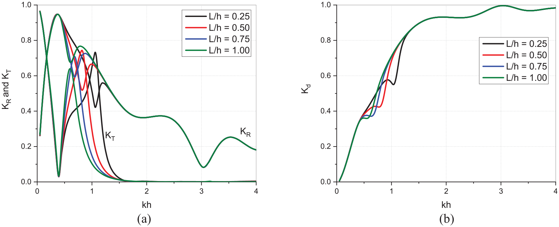
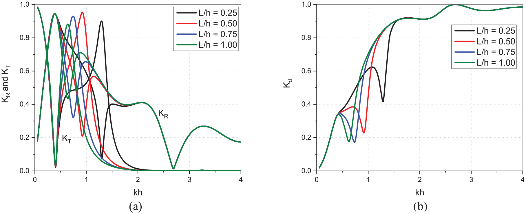
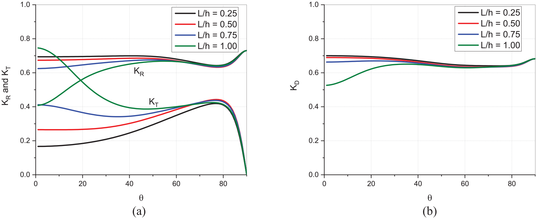
In the present section, the effect of varying the relative gap between the straight bottom U-OWC and Π-breakwater, on , and versus and angle of incidence . Figure 11(a) and (b) shows the behaviour of reflection, transmission, and dissipation coefficients for the integrated U-OWC with breakwater for various relative gap between straight bottom U-OWC and Π-breakwater. The transmission coefficient (Figure 11(a)) for all variations in is minimum within the shallow water depth , and the reflection coefficient (Figure 11(a)) within for all variations of is about , indicating that the most of the wave energy gets reflected back in the shallow water region. Consequently, the dissipation coefficient, (Figure 11(b)) for all variations of remains same within and is around as most of the wave energy is reflected back due to front wall of U-OWC. In the intermediate water depth range of , the (Figure 11(a)) shows a local minima which increases by around 23%, 13% and 13% as is increased within .
Variation of (a) and (b) versus for different in the case of straight bottom U-OWC with Π-breakwater.
In addition, the (Figure 11(a)) for all variations of shows a local maxima which decreases by around 1%, 4% and 8% as is increased within .The decreasing local maxima in and increasing local minima in within indicates that as the relative gap between the U-OWC and Π-breakwater is increased, the wave energy gets trapped within the structures which results in reduction in wave transmission and increased wave reflection. Further, the local minima of dissipated energy (Figure 11(b)) decreases by around 22%, 12% and 5% within as the relative gap between U-OWC and Π-breakwater increases from 0.25 to 1.0 which indicates a larger gap width dissipates less wave energy. Thereafter, for the wave energy transformation for all variations in is noted same wherein (Figure 11(a)) for all variations of shows a decreasing trend whereas the (Figure 11(a)) for all variations approaches to zero and wave dissipation coefficient . Thus, for the deep-water waves are not affected by the variation in the gap between U-OWC and breakwater, and the wave energy gets completely dissipated by the structure resulting in zero wave transmission and low wave reflection.
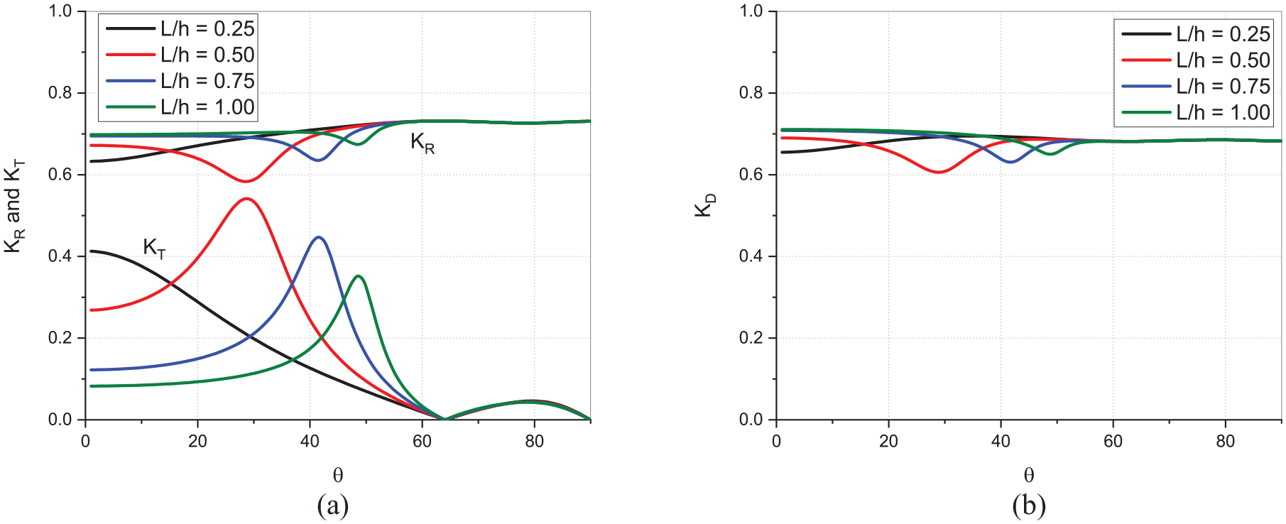
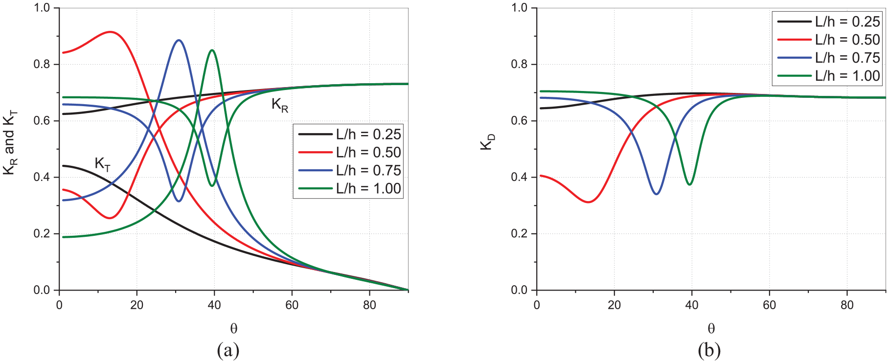
In Figure 12(a) and (b) the effect of varying the relative gap on the and is studied as a function angle of incident waves . The wave transmission (Figure 12(a)) for all variations of has a maxima within the incidence region of which decreases by around 18% and 22% as is increased from 0.5 to 1. The occurrence of the maxima is observed at higher angle of incidence as is increased. In addition, the wave reflection (Figure 12(a)) has minima which increases by around 8% and 6% as is increased from 0.5 to 1. Further, the wave energy dissipation (Figure 12(b)) is noted to have minima at the specific angles of incidence where has maxima. As the gap is increased between the U-OWC and Π-breakwater, the waves need a higher angle of incidence to cross the structure and have higher transmission, but the larger gap also causes the wave energy to get dissipated which results in minima in wave transmission. At a critical angle of , the for all variations of is zero and thereafter for any increase in angle of incidence within , the wave transmission is very less and is around .
Variation of (a) and (b) versus for different in the case of straight bottom U-OWC with Π-breakwater.
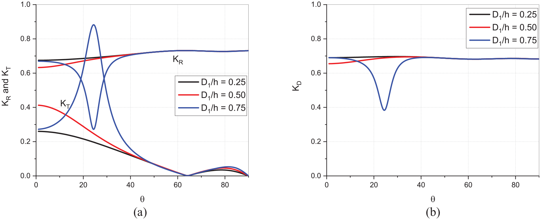
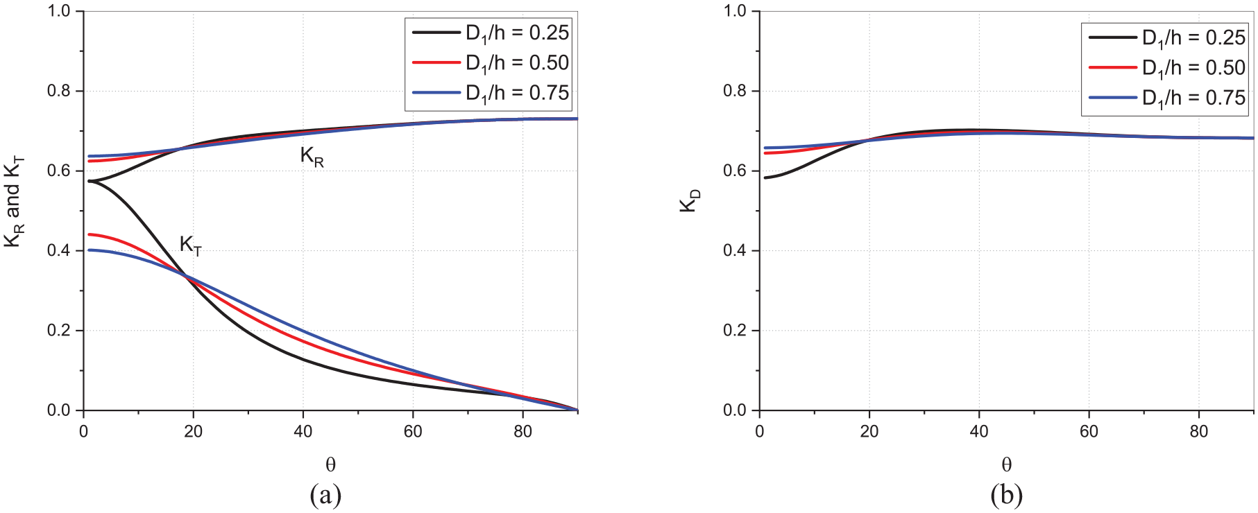
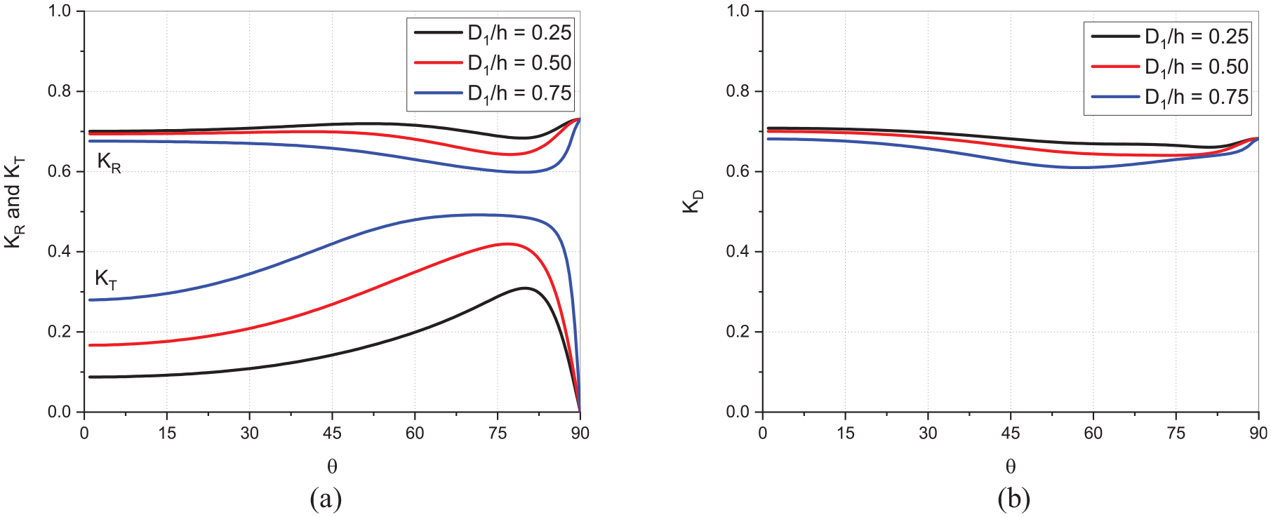
In Figure 13(a) and (b), the and is analysed versus angle of incidence to study the effect of varying the relative draft of the Π-breakwater . The transmission coefficient (Figure 13(a)) steadily declines as the angle of incidence is increased from to for all variations in , however, for , the wave transmission has a maximum value at around . Moreover, the wave reflection (Figure 13(a)) and wave dissipation (Figure 13(b)) for all variations in is almost same with the increase in the angle of incidence is except for which has a minima in and corresponding to the maxima in . The could prove to be inefficient as a breakwater since at lower angles of incidence most of the wave energy is transmitted instead of being dissipated or reflected. At a critical angle of incidence, , the wave transmission approaches zero for all variations in , and consequently, the reflection and dissipation are noted to be high of around .
Variation of (a) and (b) versus for different in the case of straight bottom U-OWC with Π-breakwater.
Inclined bottom U-OWC with π-breakwater
The inclined bottom U-OWC integrated with Π-breakwater is studied on varying the relative gap between U-OWC and Π-breakwater as well as relative draft of Π-breakwater to study the effect on the wave transformation characteristics. The integrated structure is considered to have , , , , , , , and , unless otherwise specified.
In Figure 14(a) and (b), the effect of varying the relative gap between the inclined bottom U-OWC and Π-breakwater is studied on analysing the wave reflection, transmission, and dissipation coefficients. The behaviour of all the variations of the relative gap in case of inclined bottom U-OWC is observed similar to that of a straight bottom U-OWC. The wave transmission (Figure 14(a)) has a local minima in the shallow water depth of for all variations in since most of the wave energy is reflected back as indicated by the maxima in (Figure 14(a)). In the intermediate water depth of , the has maxima which increases by around 3% as increases from 0.25 to 0.75 and thereafter decreases by around 6% as increases from 0.75 to 1.0. Further, the wave reflection coefficient (Figure 14(a)) has local minima which increases by around 228%, 39% and 37% as the is increased from 0.25 to 1.0. In addition, the wave dissipation (Figure 14(b)) has local minima which decreases by around 46%, 21% and 0% as the is increased from 0.25 to 1.0. The wave energy is transmitted by a higher percentage as the relative gap is increased since the wave energy is not dissipated by interfering interaction caused by the Π-breakwater. In the intermediate and deep-water region of , the wave energy is mostly dissipated and is around (Figure 14(b)) and has low reflection coefficient as well as zero transmission coefficient.
Variation of (a) and (b) versus for different in the case of inclined bottom U-OWC with Π-breakwater.
In Figure 15(a) and (b), the effect of varying the relative gap between the inclined bottom U-OWC and Π-breakwater is analysed on studying the wave reflection, transmission, and dissipation coefficients for different angle of wave incidence . There exists an angle of incidence wherein the wave transmission (Figure 15(a)) has a maxima as the is increased from 0.5 to 1.0. Further, the wave reflection (Figure 15(a)) is observed to be almost invariable as the angle of incidence increases for , whereas, as the is increased from 0.5 to 1.0, minima in is observed which increases by around 24% and 16%. In addition, the wave dissipation (Figure 15(b)) is analogous in behaviour to wave reflection with the minima increasing by around 6% and 12% as the is increased from 0.5 to 1.0. The observations indicate that for an inclined bottom U-OWC integrated with Π-breakwater, increasing the relative gap beyond 0.25 results in the waves getting excessively transmitted for the angles of incidence .
Variation of (a) and (b) versus for different in the case of inclined bottom U-OWC with Π-breakwater considering .
In Figure 16(a) and (b), the effect of varying the relative draft of Π-breakwater, on the wave reflection, transmission, and dissipation is analysed versus the angle of incidence . It is observed that increasing the angle of incidence has minimal effect on the wave reflection coefficient (Figure 16(a)) as it is almost consistent for all irrespective of variations in . On the other hand, the wave transmission coefficient (Figure 16(a)), is seen to be steadily decreasing as the is increased and the maxima occurring within increases as is increased from 0.25 to 0.75. Further, the wave dissipation coefficient (Figure 16(b)) is also observed to be almost invariant for all variations in . The wave transformation parameters in the present study, indicates that varying the relative draft of the Π-breakwater does not have a significant effect due to extra space underneath the U-OWC bottom allowing the waves to pass through smoothly.
Variation of (a) and (b) versus for different in the case of inclined bottom U-OWC with Π-breakwater considering .
Curved bottom U-OWC with π-breakwater
The curved bottom U-OWC integrated with Π-breakwater is studied in terms of wave transformation parameters while varying the relative gap between the U-OWC and the Π-breakwater, as well as the relative draft of the Π-breakwater. The structure is considered to have , , , , , , , and , unless otherwise specified.
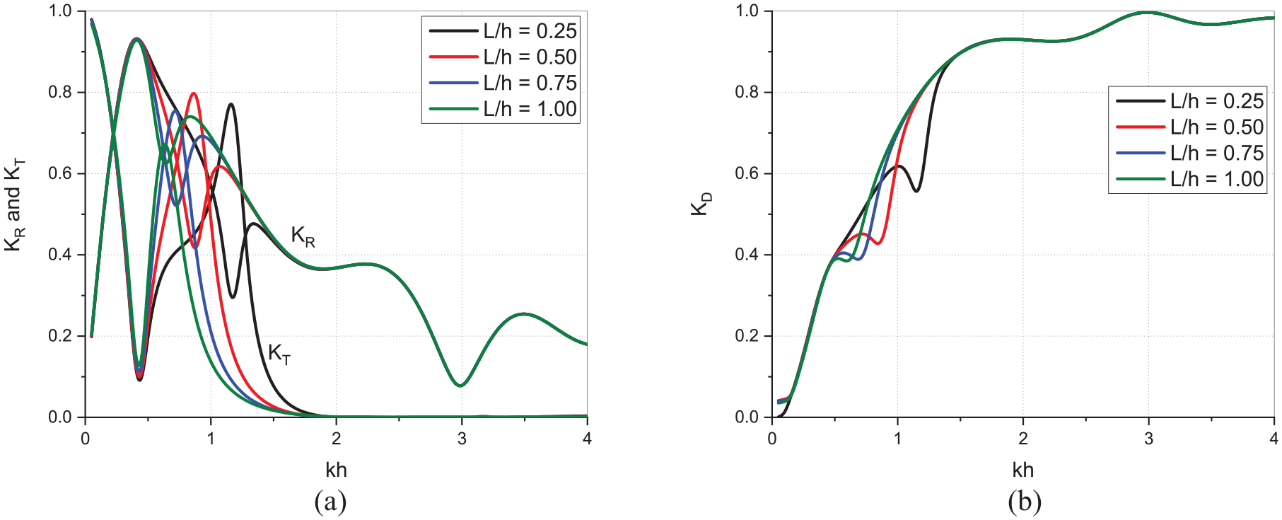
In Figure 17(a) and (b), the behaviour of and versus non-dimensional wave number for curved bottom U-OWC integrated with Π-breakwater is studied while varying the relative gap between curved bottom U-OWC and Π-breakwater. The wave transmission coefficient (Figure 17(a)) has local minima in the shallow water depth of whereas the wave reflection coefficient (Figure 17(a)) has maxima for all variations in . In the intermediate water depth of , has local maxima which decrease by around 0%, 5% and 10% as the is increased from 0.25 to 1.0, whereas the has local minima which increases by around 41%, 24% and 19%, and, correspondingly, (Figure 17(b)) has local minima which decreases by around 22%, 9% and 0%. The variation in the wave transformation is due to the fact that with increasing the relative gap between the U-OWC and Π-breakwater provides the waves to get reflected back instead of the energy getting dissipated resulting in increased wave reflection and reduced transmission. In the deep water region of , the and for all variations in approach zero whereas the approaches maximum value, indicating that most of the deep water wave energy gets dissipated by the integrated structure irrespective of the variation in .
Variation of (a) and (b) versus for different in the case of curved bottom U-OWC with Π-breakwater.
In Figure 18(a) and (b), the effect of varying the relative gap between the curved bottom U-OWC and Π-breakwater on the wave reflection, transmission, and dissipation is analysed versus angle of wave incidence . The wave transmission coefficient (Figure 18(a)) decreases as the angle of incidence is increased till for increasing from 0.75 to 1.0 and increases as is increased from 0.25 to 0.5. Further, the wave reflection coefficient (Figure 18(a)) increases as the angle of incidence is increased till for and is almost same as is increased from 0.25 to 0.75. The wave dissipation coefficient (Figure 18(b)) is noted similar to wave reflection. The increased gap between the structures facilitates waves to get reflected back as the angle of incidence is increased instead of getting transmitted or dissipated. For higher angles of incidence , the for all variations in approaches zero whereas wave reflection and dissipation coefficients increase by around 14%.
Variation of (a) and (b) versus for different in the case of curved bottom U-OWC with Π-breakwater.
In Figure 19(a) and (b), the effect of varying the relative draft of Π-breakwater on the behaviour of wave reflection, transmission, and dissipation coefficient is analysed for different angle of wave incidence . The wave transmission coefficient (Figure 19(a)) increases with increase in angle of incidence up to and the values of are consistently lower by around 39% and 47% as is increased from 0.25 to 0.75. A decrease in value of wave transmission with increase in relative draft of breakwater is expected as the waves face more hindrance due to increased interaction caused by a larger draft. The increased interaction of waves with a larger draft result in increased wave reflection and dissipation coefficient. The wave reflection coefficient (Figure 19(a)) increases by around 8% and 6% and the wave dissipation coefficient (Figure 19(b)) increases by around 6% and 3% as the is increased from 0.25 to 0.75 for . In the case of , the for all variations in approaches zero as all the wave energy is either reflected or gets dissipated.
Variation of (a) and (b) versus for different in the case of curved bottom U-OWC with Π-breakwater.
Wave force on π-breakwater and U-OWC
The waves impound mostly on the structures near the water surface, so the calculation of wave induced force is very essential to aid in the designing process. The top lip wall of the U-OWC and the front surface of the Π-breakwater are mostly exposed to the action of waves. So, in the present study the analysis id performed for the wave force on top lip wall of the U-OWC and the front surface of the Π-breakwater.
Straight bottom U-OWC with π-breakwater
The wave force on the top lip wall of the U-OWC and the front surface of the Π-breakwater for straight bottom U-OWC varying the relative gap between U-OWC and Π-breakwater and the relative ‘U’ channel width versus wavenumber for normal incident waves and as a function of angle of incidence for a specified wavenumber. The structural parameters considered are , , , , , , , and , unless otherwise specified.
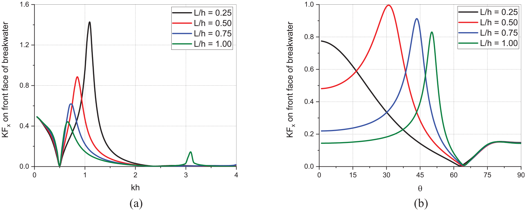
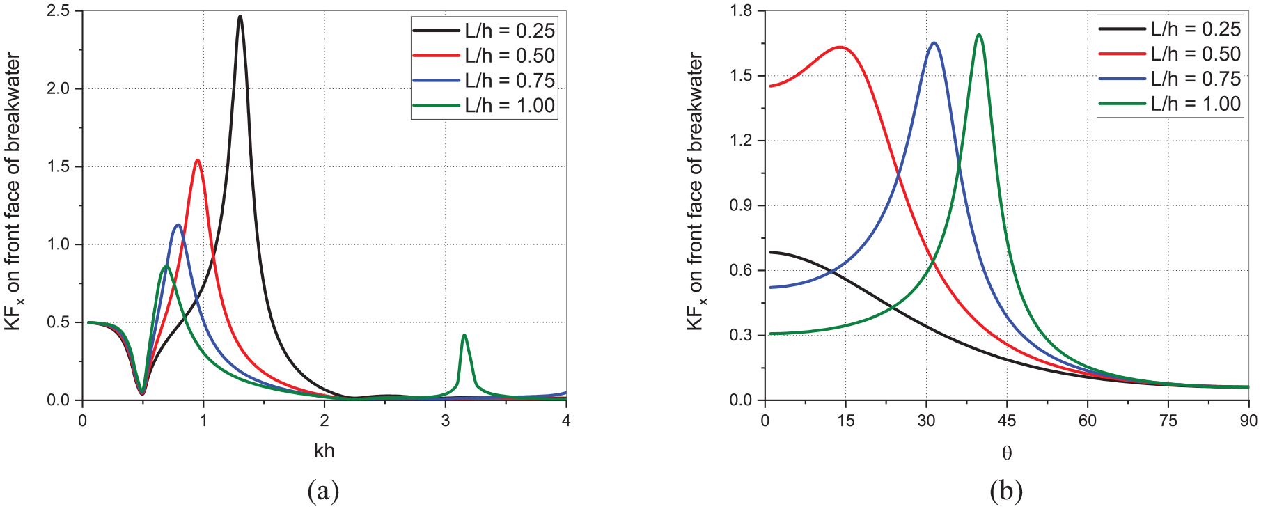
In Figure 20(a) and (b), the effect of varying relative gap between straight bottom U-OWC and Π-breakwater on the non-dimensional horizontal wave force coefficient acting on the front face of the Π -breakwater is studied as a function of wavenumber , and as a function of angle of incidence (with ). The (Figure 20(a)) for all variations of approaches minima in the shallow water depth region of . In the intermediate water depth of , the has maximum value that decreases by around 37%, 30% and 27% as is increased from 0.25 to 1.0. As the relative gap is increased, the wave energy gets dissipated and hence the wave force acting on the Π-breakwater is reduced. Similar phenomenon can be observed for increasing angle of wave incidence in Figure 20(b) wherein for deep water depth of the approaches zero for all variations in . As the angle of wave incidence is increased within , the (Figure 20(b)) shows a maxima which decreases by around 8% and 7% as is increased from 0.5 to 1.0. Further, within , the for all variations in approaches zero and on increasing the angle of incidence within , the wave force is minimum and is around .
Variation of on front face of breakwater versus (a) for and (b) for in the case of straight bottom U-OWC with Π-breakwater for different .
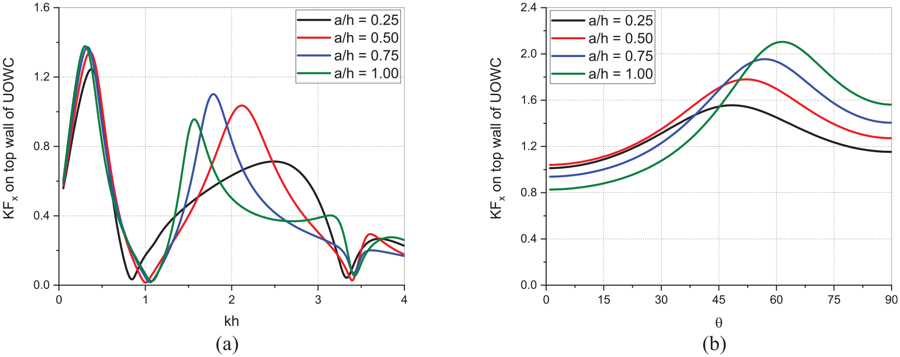
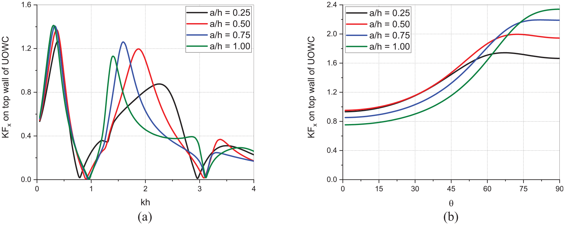
In Figure 21(a) and (b), the effect of varying the relative U-channel width of straight bottom U-OWC on the non-dimensional horizontal wave force coefficient on the top wall of U-OWC is studied as a function of wavenumber , and as a function of angle of incidence (with ) respectively. The (Figure 21(a)) for all variations in has maxima in the shallow water depth of . In the higher wavelength region of intermediate water depth , approaches zero and thereafter in intermediate water depth of , the has a global maxima which increases by around 46% and 6% as is increased from 0.25 to 0.75, and decreases by around 14% as is increased from 0.75 to 1.0. As the relative width of the U-channel is increased, the waves interact less with the bottom wall of the U-OWC and directly hit the top wall resulting in higher wave forces, but, the phenomenon is limited up to a certain after which increasing the width interferes with the waves and causes the energy to get dissipated resulting in lower wave forces on the top wall. In the deep-water region of , the for all variations approaches zero and is low as the shorter wavelength waves dissipate all their energy resulting in lesser wave forces. On increasing the angle of incidence (Figure 21(b)), all variations in have a critical angle wherein the has a maxima, and the maxima shifts towards higher by around 14%, 9% and 7% as is increased from 0.25 to 1.0. The maxima in occurs at a critical angle of incidence which needs to be considered in the design of the structure.
Variation of on top wall of U-OWC versus (a) for and (b) for in the case of straight bottom U-OWC with Π-breakwater for different .
Inclined bottom U-OWC with π-breakwater
Wave force on the top wall of the inclined bottom U-OWC and the front face of the Π-breakwater is studied to analyse the effect of varying the relative gap between inclined bottom U-OWC and Π-breakwater on acting on the front face of Π-breakwater and the effect of varying the relative ‘U’ channel width on acting on the top wall of the U-OWC considering , , , , , , , and , unless otherwise specified.
In Figure 22(a) and (b), the effect of varying the relative gap between inclined bottom U-OWC and Π-breakwater on acting on the front face of Π-breakwater is studied as a function of wavenumber and angle of wave incidence . The wave force (Figure 22(a)) acting on the front face of the Π-breakwater behaves in a manner similar to that in the straight bottom U-OWC integrated structure. However, the magnitude of wave force acting on the Π-breakwater is higher in case of inclined bottom U-OWC as compared to the straight bottom U-OWC. The maxima of occurring in the intermediate water depth of is higher by around 76%, 75%, 103% and 95% for varying from 0.25 to 1.0 in case of inclined bottom U-OWC as compared to straight bottom U-OWC. This increase in wave forces could be due to higher volume of water impounding on the breakwater as there is less hindrance to the wave motion owing to the reduced surface area of the inclined bottom U-OWC. The as a function of (Figure 22(b)) has a maxima within the angle of incidence range which increases by around 0.6% and 2% as is increased from 0.5 to 1.0. For higher angles of incidence within , the approaches zero for all variations in .
Variation of on front face of the Π-breakwater versus (a) for and (b) for in the case of inclined bottom U-OWC with Π-breakwater for different .
In Figure 23(a) and (b), the effect of varying the relative ‘U’ channel width on the horizontal wave force acting on the top wall of the inclined bottom U-OWC is studied as a function of wavenumber and angle of wave incidence . The behaviour of across the wavenumbers is similar to that of straight bottom U-OWC integrated structure, with the distinction being the increased magnitude of occurring in the intermediate water depth . As the is increased from 0.25 to 1.0, the maxima in on the top wall are higher by around 22%, 15%, 13% and 19% in the case of inclined bottom U-OWC as compared to straight bottom U-OWC. Due to lesser volume of the internal chamber of the inclined bottom U-OWC, the amount of wave energy entering inside the chamber is less hence the energy dissipated is lesser and the wave energy gets impounded on the top wall resulting in higher wave forces. Upon increasing the angle of wave incidence (Figure 23(b)), the on the top wall increases up to a certain angle of incidence and thereafter stays almost same value. The angle of incidence at which is maximum could be termed as the critical angle of incidence. The maxima of increases by around 15%, 10% and 6% as the is increased from 0.25 to 1.0. The increase in maxima of could be due to unhindered wave energy acting on the top wall resulting in lesser energy being dissipated by in the wider ‘U’ channels.
Variation of on top wall of U-OWC versus (a) for and (b) for in the case of inclined bottom U-OWC with Π-breakwater for different .
Curved bottom U-OWC with π-breakwater
The horizontal wave force acting on the top wall of curved bottom U-OWC and on the front face of the Π-breakwater is analysed on varying the relative gap between U-OWC and Π-breakwater as well to study its effect on the wave force on the front face of the Π-breakwater. The structural parameters considered are , , , , , , , and unless otherwise specified.
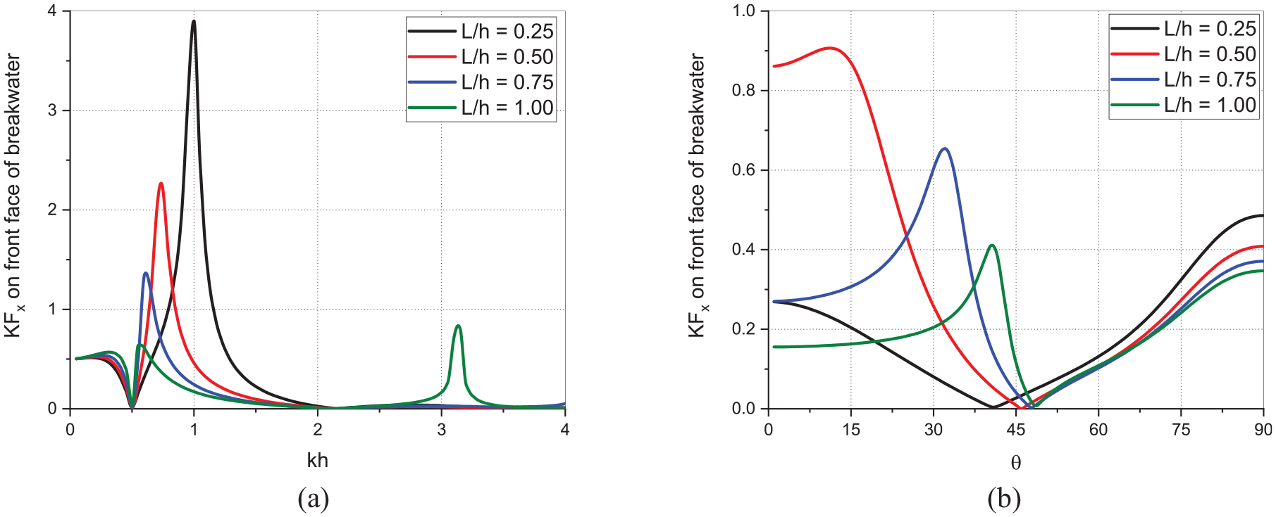
In Figure 24(a) and (b) the effect of varying the relative gap between curved bottom U-OWC and Π-breakwater on the horizontal wave force component acting on the front face of the Π-breakwater is studied as a function of wavenumber and angle of wave incidence . The acting on the front face of the Π-breakwater integrated with curved bottom U-OWC has maxima in the intermediate water depth region of (Figure 24(a)). However, the maxima of are higher than the case of inclined bottom U-OWC. As the is varied from 0.25 to 1.0, the maxima of are higher by around 178%, 150%, 119% and 45% as compared to straight bottom U-OWC and is around 58%, 42%, 8%, 0% higher as compared to inclined bottom U-OWC. The normal incident waves encounter less resistance to the movement of waves by a curved bottom U-OWC due to lesser surface area than straight bottom U-OWC and the wave force acting on the Π-breakwater are amplified due to the smooth path offered by the curved bottom of the U-OWC. As the angle of wave incidence is increased within , the shows maxima which is lower by around 27% and 36% as the is increased from 0.5 to 1.0. There exists a critical angle within where the for all variations in is zero. As the angle of incidence is increased beyond , the wave force increases again. Due to the oblique incidence of waves, the wave energy directly impounds the Π-breakwater and hence an increase in is observed, however, at the critical angle of incidence, the energy is completely dissipated leading to zero wave force.
Variation of on front face of breakwater versus (a) for and (b) for in the case of curved bottom U-OWC with Π-breakwater for different .
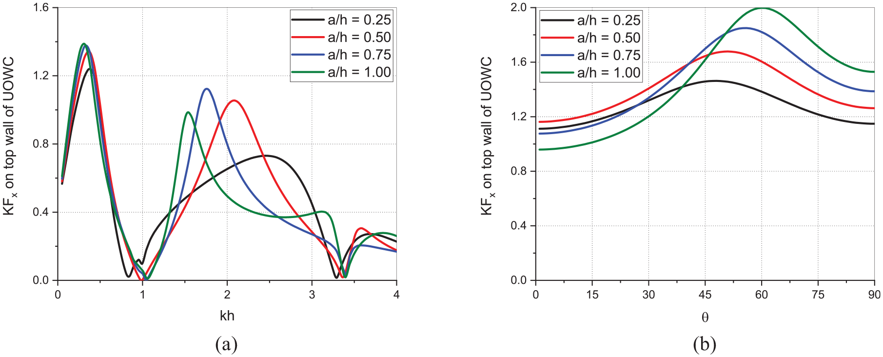
In Figure 25(a) and (b), the effect of varying the ‘U’ channel width of curved bottom U-OWC on the horizontal wave force component acting on the top wall of the U-OWC is analysed as a function of wavenumber and angle of wave incidence . The variation of as a function of is similar to that in the case of straight and inclined bottom U-OWC. The maxima in (Figure 25(a)) occurs in the intermediate water depth of as is varied from 0.25 to 1.0 is lower by around 16%, 12%, 11% and 13% as compared to that of inclined bottom U-OWC and is same in magnitude as compared to straight bottom U-OWC. The curved bottom U-OWC having more internal chamber volume than inclined bottom U-OWC, diverts the wave energy inside the chamber rather than acting on the top wall resulting in lesser than inclined bottom U-OWC. As the angle of wave incidence is increased, a maxima in occurs around which is higher by around 15%, 10% and 8% as the is increased within . The critical angle of wave incidence where the maxima in occurs is considered for proper design of the structure.
Variation of on top wall of U-OWC versus (a) for and (b) for in the case of curved bottom U-OWC with Π-breakwater for different .
Comparative study of bottom profiles of U-OWC integrated with π-breakwater
On analysing various parameters under different geometrical configurations of the three different bottom profile of U-OWC integrated with Π-breakwater, a comparative study is presented in this section. The comparative study is performed for three different bottom profile of U-OWCs to assess the performance of the integrated systems.
Efficiency, radiation susceptance and conductance coefficients
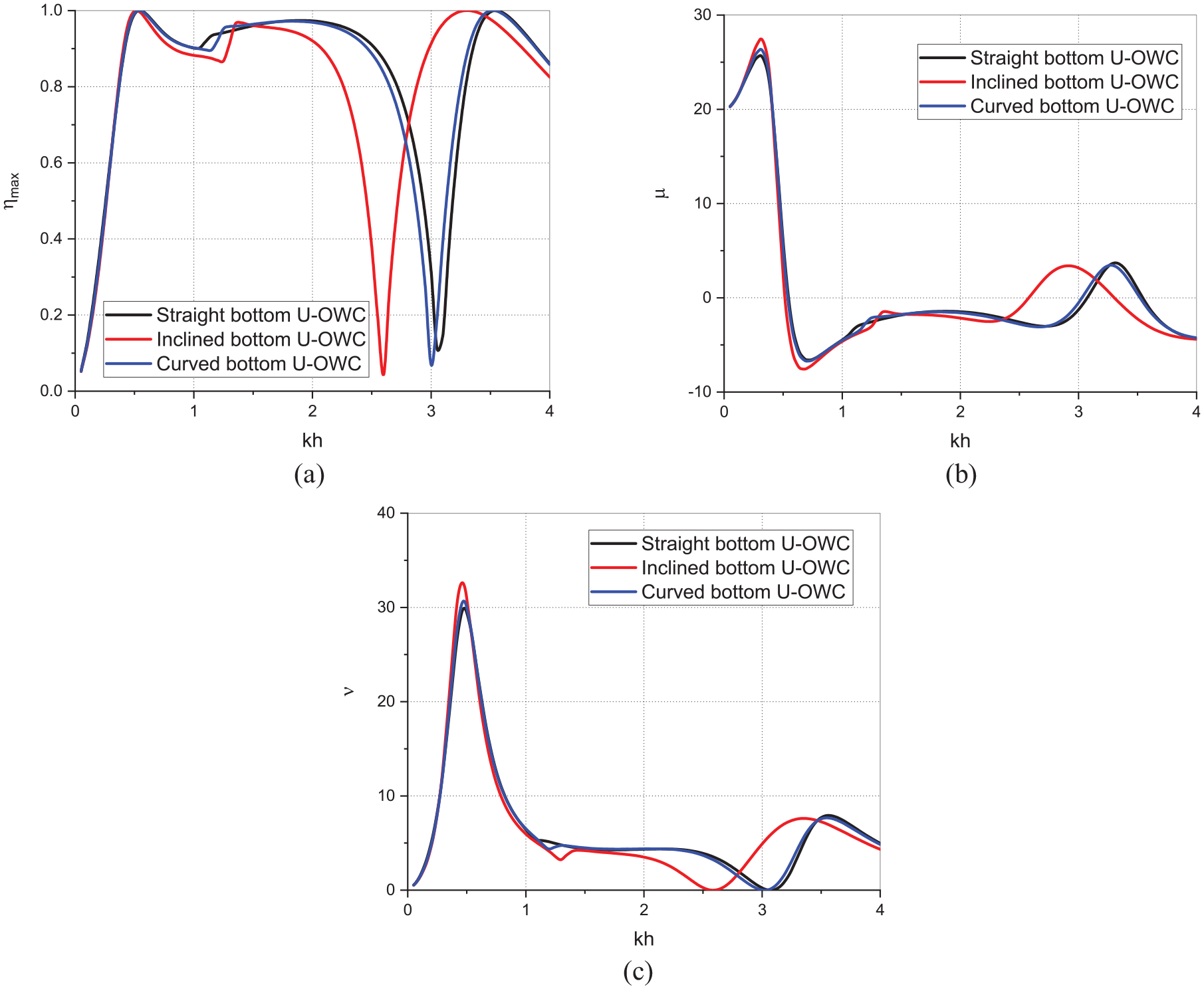
The performance of the integrated U-OWC with Π-breakwater in terms of , and as a function of are studied in Figure 26(a) to (c) considering , , , , , , , , and for straight, inclined and curved bottom U-OWC. It is observed that the (Figure 26(a)) for straight and curved bottom are almost identical with minuscule phase shift difference, whereas the inclined bottom U-OWC while showing a similar trend as the straight and curved bottom configurations, exhibits the drop in efficiency at a lower wavenumber, . Similar difference is also noticeable in the behaviour of (Figure 26(b)) wherein the second peak of the curve and in (Figure 26(c)), wherein the trough of the curve occur at a lower corresponding to the drop in . Further, on varying the geometry of the internal chamber, the natural frequency of the system varies which manifests the phase difference in the theoretical maximum efficiency. Overall, the performance of the different bottom profile U-OWC is similar in nature, but the inclined bottom U-OWC underperforms within the wavenumber .
Variation of (a) , (b) and (c) versus for straight, inclined and curved bottom profile of U-OWC integrated with Π-breakwater.
Reflection, transmission and dissipation coefficients
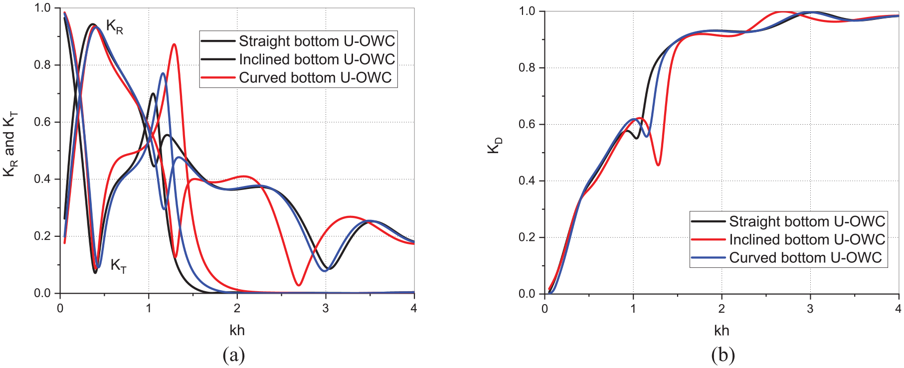
The wave reflection, transmission and dissipation coefficients for the integrated U-OWC with Π-breakwater is analyse on considering , , , , , , , and , for straight inclined and curved U-OWC bottom profiles versus non-dimensional wavenumber in Figure 27(a) and (b).
Variation of (a) , and (b) versus for straight, inclined and curved bottom profile of U-OWC integrated with Π-breakwater.
The wave reflection coefficient (Figure 27(a)) on varying bottom profile of OWC indicates that for the wave reflection attains maximum value and thereafter within the is noted lowest for inclined bottom, followed by curved bottom and the straight bottom configuration. The inclined bottom configuration provides the least resistance to the flow of waves from underneath the structure leading to highest wave transmission and hence lowest wave reflection. Conversely, the wave transmission coefficient (Figure 27(a)) for different configurations of bottom profile of OWC are almost same till , thereafter within the range of , the local maxima in is observed for inclined bottom, followed by curved and straight bottom profile of OWC. Further, the wave energy dissipation is noted lowest in the case of inclined bottom, which can be seen in the behaviour of (Figure 27(b)). In the higher wavenumbers, , the is zero for all configurations. The and in this range is same for straight and curved bottom configurations, but inclined bottom configuration shows a phase shift towards lower values of .
Wave force coefficient
The wave force on the structures affects the longevity of the structure under the action of ocean waves and hence it is important to analyse the integrated system considering the performance of the U-OWC as energy conversion device and also the breakwater.
Wave force on front face of breakwater
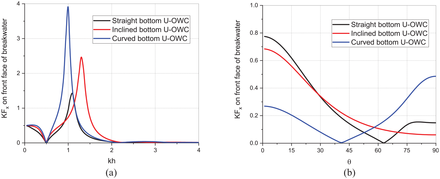
The wave force coefficient in Figure 28(a) and (b) on the front face of the breakwater is analysed verses non-dimensional wave number for normal angle of incidence and varying angle of incidence for the straight, inclined and curved bottom U-OWC considering the geometry of the structures as , , , , , , , , and . The maximum wave force on the front face of the breakwater is observed within in the regime of intermediate water depth (Figure 28(a)). The waves flowing past the U-OWC impinge upon the face of the breakwater, so more force acts on the breakwater due to lesser obstruction to the flow. On changing the bottom profile of the U-OWC, the flow of water streamlines, so inclined bottom offers better flow than straight bottom, and curved bottom offers best flow conditions, therefore on the breakwater is maximum in case of curved bottom, followed by inclined and minimum in case of straight bottom. Further on varying versus angle of incidence (Figure 28(b)), the behaviour of for straight and curved bottom is observed to approach minimum within which indicates the presence of a critical angle where the wave force becomes zero. The critical angle for curved bottom is lower than that of straight bottom. The inclined bottom does not show any critical angle, rather it is characterised by a gentle exponential declining curve.
Variation of on front face of breakwater versus (a) for normal incident wave and (b) for in the case of straight, inclined and curved bottom profile of U-OWC integrated with Π-breakwater.
Wave force on top wall of U-OWC
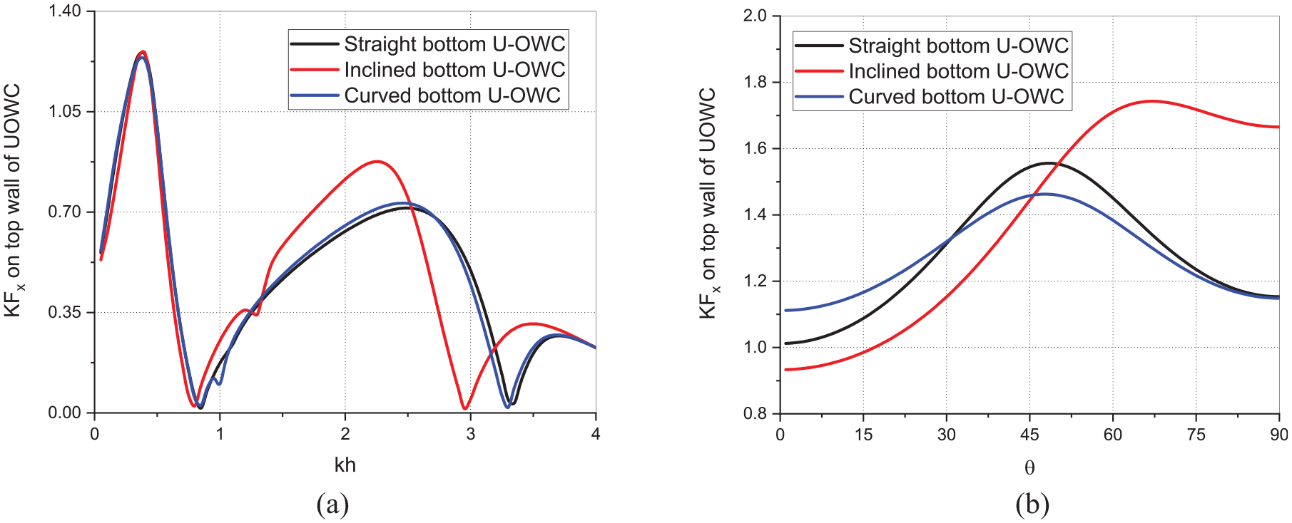
The wave force coefficient on the top wall of U-OWC is compared for the straight, inclined and curved bottom U-OWC while considering geometry of the structures as , , , , , , , , and as a function of (Figure 29(a)) and as a function of (Figure 29(b)) considering . The behaviour of on top wall of U-OWC versus (Figure 29(a)) for straight and curved bottom is almost identical with minuscule phase difference. The inclined bottom U-OWC shows behaviour identical to the other two configurations till , and thereafter follows the same pattern, but with a noticeable phase shift and a higher peak value in the intermediate water depth region. The straight bottom U-OWC provides largest volume of water column inside the chamber, followed by curved bottom. On the other hand, for curved bottom, the smooth curve allows water to move up and down smoothly without getting pushed out and applying force on top wall. Further, the inclined bottom provides least volume of water column and facilitates water to flow out of the chamber causing more force on the top wall. On varying versus (Figure 29(b)), the maxima in is noted within for straight and curved bottom but the straight bottom has a higher than curved bottom. Further, the inclined bottom configuration shows an exponential rise and a brief decline after reaching the peak value, with the peak being considerably higher than the other two configurations. The angle where the configurations show peaks of can be termed as critical angle.
Variation of on top wall of U-OWC versus (a) for normal incident wave and (b) for in the case of straight, inclined and curved bottom profile of U-OWC integrated with Π-breakwater.
The integrated structure in this study is assumed to be fixed near the free surface. As the wave energy is concentrated near the free-surface, so the wave energy converter device is placed near the surface. However, few other considerations might arise from a structure being placed near the surface of the sea, such as, potential disruption of shipping routes or fishing areas, possible adverse effect on aesthetics if the structure is placed near to a public shore, environmental impact emerging from placing large objects in the ocean ecosystem. A change in draft of the structure greatly impacts the energy conversion efficiency as well as the wave transformation characteristics, hence a fluctuating mean sea level could be incorporated into any future investigations. The piles restraining the structure in place also warrant a different detailed study in terms of their design and possible effects on the structure’s hydrodynamic performance, although the authors do not expect much effect as majority of the wave energy is already been utilised by the near-surface structure.
Conclusions
In the present study, the hydrodynamic performance of a fixed floating U-OWC with straight, inclined, and curved bottom integrated with Π-breakwater is analysed. The energy conversion efficiency, radiation susceptance and radiation conductance of different U-OWC are studied while varying the relative ‘U’ channel width and relative draft of the U-OWC. Moreover, the wave transformation parameters such as the wave reflection, transmission and dissipation coefficients are analysed while varying the relative gap between the U-OWC and Π-breakwater and the relative draft of the Π-breakwater. In addition, the horizontal wave force component acting on the top wall of the U-OWC and on the front face of the Π-breakwater are studied while varying the relative gap and the relative ‘U’ channel width. The conclusions drawn from the study are as follows:
The maximum efficiency for the U-OWC is noted minimal for all three different bottom profiles of U-OWC on increasing the relative U-channel width .
The maximum efficiency improves for all three bottom profiles of U-OWC, as the relative draft of the device is increased. However, the relative draft is recommended as optimum value as the performance of the device is marginally less than but can have less construction costs due to the requirement of lesser amount of material.
In all three different bottom profiles, as the relative gap between U-OWC and Π-breakwater is increased, the decreases and increases, and correspondingly wave dissipation decreases in the long wave regime of intermediate water depth.
In the case of straight bottom U-OWC integrated with Π-breakwater, there exists a critical angle of wave incidence, , where becomes zero for varying and . On the other hand, the critical angle is absent in case of inclined and curved bottom U-OWC.
The wave force coefficient on the front face of the Π-breakwater decreases with increase in relative gap between the structures for all three bottom profiles of U-OWC. A critical angle of incidence exists for straight and curved bottom U-OWC where the wave force becomes zero. In the case of curved bottom U-OWC, the angle varies slightly for different but is in the vicinity of .
The wave force coefficient on the top lip wall of the U-OWC increases with increase in relative U-channel width up to and then decreases slightly for in all three different bottom profiles of U-OWC.
The behaviour of the U-OWC device in terms of efficiency for all three bottom profiles is almost same except slight phase differences, indicating change in natural frequency of the U-OWC due to change in bottom profile of the internal chamber.
The wave force on the top lip wall of U-OWC has same behaviour for all three bottom profiles, however there is a slight phase shift in the case of inclined bottom and the values of are noted slightly higher as compared to the other two cases. On varying the angle of incidence, the for inclined bottom U-OWC shows a significant shift and increase in the maxima in case of inclined bottom U-OWC.
Footnotes
Appendix
Acknowledgements
The authors are grateful to the Ministry of Education (MoE) Government of India and National Institute of Technology Karnataka Surathkal for providing necessary facilities for pursuing the research work.
Declaration of conflicting interests
The author(s) declared no potential conflicts of interest with respect to the research, authorship, and/or publication of this article.
Funding
The author(s) disclosed receipt of the following financial support for the research, authorship, and/or publication of this article: DK acknowledges the partial support from Ministry of Ports, Shipping and Waterways, India through the research grant no. DW/01013(13)/2/2021-Development Wing.
ORCID iDs
R. Muduli
D. Karmakar
Data Availability Statement
The data that support the findings of this study are available from the corresponding author upon reasonable request.
References
1.
HeathTV.A review of oscillating water columns. Philos Trans A Math Phys Eng Sci2012; 370(1959): 235–245.
2.
SundarVMoanTHalsJ. (2010). Conceptual design of OWC wave energy converters combined with breakwater structures. Proceedings of 29th International Conference on Offshore Mechanics and Arctic Engineering, 6th -11th June, 2010, Sanghai, China, OMAE2010-20508, 479–489.
3.
FalcãoAFOHenriquesJCC. Oscillating-water-column wave energy converters and air turbines: A review. Renew Energy2016; 85: 1391–1424.
4.
GrawKU. (1996). Wave energy breakwaters-a device comparison. Proc. Conference in Ocean Engineering, IIT Madras, India.
5.
OhnedaHIgarashiSShinboO, et al. (1991). Construction procedure of a wave power extracting caisson breakwater. Proceedings of 3rd Symposium on Ocean Energy Utilization, Tokyo, 171–179.
6.
TakahashiSNakadaHOhnedaH, et al. Wave power conversion by a prototype wave power extracting caisson in Sakata port. Coast Eng1992; 1(23):3440–3453.
7.
Torre-EncisoTOrtubiaIde AguiletaL, et al. 2009). Mutriku Wave Power Plant: from the thinking out to the reality. Proceedings of 8th European Wave and Tidal Energy Conference, Uppsala, Sweden, 319–329.
8.
BoccottiP.On a new wave energy absorber. Ocean Eng2003; 30(9): 1191–1200.
9.
NingDZGuoBMWangRQ, et al. Geometrical investigation of a U-shaped oscillating water column wave energy device. Appl Ocean Res2020; 97: 102105.
10.
BoccottiP.Comparison between a U-OWC and a conventional OWC. Ocean Eng2007; 34(5–6): 799–805.
11.
BoccottiPFilianotiPFiammaV, et al. Caisson breakwaters embodying an OWC with a small opening—Part II: A small-scale field experiment. Ocean Eng2007; 34(5–6): 820–841.
12.
BoccottiP.Design of breakwater for conversion of wave energy into electrical energy. Ocean Eng2012; 51: 106–118.
13.
ArenaFRomoloAMalaraG, et al. (2017). The first full operative U-OWC plants in the port of Civitavecchia. 36th International Conference on Offshore Mechanics and Arctic Engineering, Trondheim, Norway, OMAE2017-62036, 1–10, V010T09A022.
14.
RobertsIShepherdK. WaveRush: A new concept for a breakwater wave energy converter. In: Coasts, marine structures and breakwaters: Adapting to change. 2010, pp.762–773. Thomas Telford Ltd.
15.
LiuZShiHHyunBS. (2009). Practical design and investigation of the breakwater OWC facility in China. Proceedings of the 8th European Wave and Tidal Energy Conference, 304–308.
16.
RezanejadKGuedes SoaresC. Numerical study of a large floating oscillating water column device using a 2D boundary element method. In: SoaresGPeñaL (eds) Developments in maritime transportation and exploitation of sea resources. 2014, pp.951–960. London: Taylor and Francis Group.
17.
MasudaYMcCormickME.Pneumatic wave energy conversion. Coast Eng1986; 13(3): 319–333.
18.
McCormickME.A theoretical analysis of a self-propelled backward-bent duct wave energy conversion system. J Energy Resour Technol1991; 113(2): 94–100.
19.
MasudaYKubokiTThakkerA, et al. (2002). Prospect of economical wave power electric generator by the terminator backward bent duct buoy (BBDB). Proceedings of the 12th International Offshore Polar Engineering Conference, Kyushu, Japan, Vol–1, 607–613.
20.
HongDCHongSYHongSW.Numerical study on the reverse drift force of floating BBDB wave energy absorbers. Ocean Eng2004; 31(10): 1257–1294.
21.
LeeKRKooWKimMH.Fully nonlinear time-domain simulation of a backward bent duct buoy floating wave energy converter using an acceleration potential method. Int J Nav Archit Ocean Eng2013; 5(4): 513–528.
22.
JalaniMASaadMRAbdullahMF, et al. A statistical analysis for optimisation of a hybrid BBDB-PA in Mantanani Island, Sabah. J Mar Sci Eng2023; 11(2): 386.
23.
WashioYOsawaHNagataY, et al. (2000). The offshore floating type wave power device Mighty Whale: open sea tests. Proceedings of 10th International Offshore and Polar Engineering Conference, 28th May – 2nd June, 2000, Seattle, Washington, USA, ISOPE-I-00-054.
24.
OgataTWashioYOsawaH, et al. (2002). The open sea tests of the offshore floating type wave power device “Mighty Whale”: performance of the prototype. Proceedings of 21st International Conference on Offshore Mechanics and Arctic Engineering, 23rd -28th June, 2002, Oslo, Norway, OMAE2022-28335, 517–524.
25.
PenesisIMacfarlaneGJBoseN, et al. Wave energy an example of collaboration between industry and academia in Australia. J Ocean Technol2013; 8(1): 50–60.
26.
RezanejadKSouto-IglesiasAGuedes SoaresC.Experimental investigation on the hydrodynamic performance of an L-shaped duct oscillating water column wave energy converter. Ocean Eng2019; 173: 388–398.
NeelamaniSNatarajanRPrasannaDL.Wave interaction with floating wave energy caisson breakwaters. J Coast Res2006; II(39): 745–749.
29.
HeFHuangZ.Hydrodynamic performance of pile-supported OWC-type structures as breakwaters: an experimental study. Ocean Eng2014; 88: 618–626.
30.
MuduliRPatilSBKarmakarD.Hydrodynamic performance of pile restrained U-shaped OWC device using boundary element method. Eng Anal Bound Elem2024; 158: 139–159.
31.
EvansDV.Wave-power absorption by systems of oscillating surface pressure distributions. J Fluid Mech1982; 114(1): 481–499.
32.
SollittCKCrossRH.Wave transmission through permeable breakwaters. Coast Eng1972; 1(13): 1827–1846.
33.
DalrympleRALosadaMAMartinPA.Reflection and transmission from porous structures under oblique wave attack. J Fluid Mech1991; 224: 625–644.
34.
EvansDVPorterR.Hydrodynamic characteristics of an oscillating water column device. Appl Ocean Res1995; 17(3): 155–164.
35.
DengZOuZRenX, et al. Theoretical analysis of an asymmetric offshore-stationary oscillating water column device with bottom plate. J Waterway Port Coast Ocean Eng2020; 146(4): 1–13.
36.
DeanRGDalrympleRA.Water wave mechanics for engineers and scientists. Singapore: World Scientific, 1991. Vol. 2.
37.
SeeligWNAhrensJP. 1981). Estimation of wave reflection and energy dissipation coefficients for beaches, revetments, and breakwaters. US Army, Corps of Engineers, Coastal Engineering Research Centre, Fort Belvoir, VA-22060, USA.
38.
AuMCBrebbiaCA.Numerical prediction of wave forces using the boundary element method. Appl Math Model1982; 6(4): 218–228.
39.
KatsikadelisJT.The Boundary Element Method for engineers and Scientists. Oxford: Academic Press, 2016.
40.
Medina RodríguezAAMartínez FloresABlanco IlzarbeJM, et al. Interaction of oblique waves with an oscillating water column device. Ocean Eng2021; 228: 108931.
41.
VijayKGSahooT.Scattering of surface gravity waves by a pair of floating porous boxes. J Offshore Mech Arctic Eng2019; 141(5): 051803.