
Abstract
Shipborne cranes are widely used in marine engineering and are employed in more diversified working scenes. However, due to the extensive swing range of ships, it is impossible to locate the payload accurately. A constant tension control method of payload anti-swing is proposed based on the principle of linear velocity feedback. This paper establishes a dynamic model of the payload anti-swing system driven by hydraulic motors. The characteristics of the payload swing and the cable tension are obtained through the dynamic simulation. The simulation and experimental results show that the constant tension control method significantly suppresses the shipborne crane’s payload swing, and the payload anti-swing effect reaches 73% and 85.6%. It is also found that the payload swings asymmetrically under external excitation. In addition, the effects of payload asymmetric swing on cable tension, payload swing angle, and the hydraulic pump output oil pressure are studied by a payload asymmetric swing experiment, and the results show that the proposed method also has a good suppression effect on the asymmetric payload swing.
Introduction
As common engineering equipment on the deck of ships, shipborne cranes are mainly used in diversified scenes, such as material transportation, construction of water facilities, underwater salvage, and submarine geological exploration. However, when a shipborne crane is working under external excitation, the payload will swing irregularly due to the ship’s motion excitations, the wind disturbance, and the movement of the crane itself, which makes accurate positioning of the payload difficult and inefficient. For this reason, the operations of the shipborne crane system must meet stringent safety and efficiency requirements, as waves and wind currents can cause unnecessary movement of the ship and crane systems. Therefore, considering the dynamic characteristics of the shipborne crane payload system, it is of great practical significance to design an anti-swing method that can effectively suppress the payload swing.
The payload anti-swing methods of shipborne crane can be summarized into the following three types: mechanical anti-swing method, electronic anti-swing method, and mechanical-electronic anti-swing method. The mechanical anti-swing method can be traced back to Maryland researchers represented by Yuan et al., 1 who proposed a Maryland Rigging type mechanical damping device; which the sling is connected with the payload through the pulley in the crane system, and the damping of the payload swing is increased by controlling the length of the cable on the pulley and the relative movement of the pulley. By applying the Newton-Lagrange method, Wen et al. 2 introduced an optimal control method of the payload system based on the Maryland Rigging mechanical structure. The simulation proved that the method proposed by Yuan and Hunt can suppress the payload swing under a small-amplitude roll motion of the ship. Parker et al. 3 proposed a new mechanical anti-swing device named Rider Block Tagline System (RBTS). The simulation results showed that 80% of energy is saved by using this method compared to by electronic anti-swing method to achieve the same anti-swing effect. However, the RBTS method would reduce the working range of shipborne cranes. Kim and Lee 4 introduced an anti-swing strategy for container crane, which uses four auxiliary cables added to four main cables to suppress the residual oscillation, which will increase the redundancy of the system. Viet 5 designed a passive anti-swing method, by installing spring and damper in the radial payload and crane cable, which can limit the payload swing motion in environment with big vibration. Wang et al. 6 proposed a novel Cable-Driven Inverted Tetrahedron Mechanism to suppress the payload swing of shipborne crane. Wang et al. 7 studied the dynamic characteristics of the telescopic sleeve anti-swing device of the marine crane under the coupling excitation. The simulation results show that the anti-swing device can effectively restrain the swing of the payload, but it lacks the experimental verification link, and this anti-swing device has an impact on the travel of the working range of the main sling. The mechanical anti-swing method has relatively a simple structure and low modification cost. However, the control accuracy of this method is low and its application is limited. It is generally applicable to various load swing suppression.
There are two categories of the electronic anti-swing method, open-loop control, and closed-loop control. A typical open-loop technique is input shaping control, which can significantly reduce cable vibration and load oscillations during the maneuvers. Lewis et al., 8 Blackburn et al., 9 and Maleki and Singhose 10 proposed input shaping technology to suppress the vibration of the crane payload during the nonlinear slewing motions. Further, Parker et al. 11 and Glossiotis and Antoniadis 12 improved this control strategy by utilizing finite impulse response (FIR) filters. Tho et al. 13 proposed an optimal control method of payload’s skew rotation in crane systems from the perspective of a nonlinear sub-optimal time control. Shen et al. 14 presented an open-loop control strategy for sway-free point-to-point motions of the payload. Al-Fadhli and Khorshid 15 introduced a new smooth input Bezier-curve shaper to suppress residual vibration of the payload, the experimental results show that the method is effective and reliable in the process of the payload transportation.
With the further development of computer technology and control theory, closed-loop control gradually matures, and large-scale application becomes possible. It can be traced back to these documents,4,16,17 their bold attempts have inspired more scholars to study the closed-loop control technology of the payload anti-swing, such as optimizing controller design, 18 the problem of how to generate feasible inputs for the control system,19,20 and the method of optimizing controller parameter setting or unknown disturbance parameter setting.21–26 After all, these are important to the performance of the control system. Kim and Lee 4 designed a tension assignment for the auxiliary cables and a model-based PID control algorithm to suppress the residual oscillation of the spreader. Neupert et al. 27 proposed a model predictive control method to solve the problem of payload swing and tracking control, and the experimental results showed that this method can improve the efficiency of material handling and ensure the safety of operation. Zhai et al. 28 designed an adaptive fuzzy controller based on nonlinear observer to solve the relative motion problem of cargo and ship deck caused by the internal and external environmental interference of offshore crane system. The experiment shows that the controller can maintain the stability of cargo relative to ship deck. However, this study did not consider the influence of the shape of the cargo and the motion of the spherical pendulum on the control performance of the controller. Jensen et al. 29 presented an anti-swing controller which utilizes payload independent velocity control in combination with kinematic transformations to solve the problem of anti-swing control for hydraulically actuated cranes. Yang and Ouyang 30 used an adaptive control method to study the payload swing problem of distributed mass beams (DMB) in crane system, and experiment results verified that the controller can adequately eliminate the swing angles of DMB. One of its highlights is the research on anti-swing of DMB type payload. Furthermore, all kinds of shipborne crane dynamic modeling methods and control strategies are further presented in the review paper. 31 In general, the electronic anti-swing method has advantages in response speed and control precision, but high-power consumption.
The mechanical-electronic anti-swing method is the further combination of the above two anti-swing technologies. Ku et al. 32 designed a tagline proportional–derivative control method for suppressing the payload swing. Numerical simulations and experimental results showed that the proposed method can effectively suppress the payload swing. Hu et al. 33 presented a method to calculate the optimal interactive tensions that guarantee the best anti-pendulation capability, and the effectiveness of the mothed was verified by experiments. Further, Ren et al. 34 managed to design an automatic control solution for general offshore floating lifting operations with a complex-shaped payload and a significant number of lift wires. The main advantage of his control strategy is the model-free characteristic, which overcomes the design difficulties caused by the configuration complexity and nonlinearities of lift wires. Aim at the control problem of the combined sway and skew motion for a bifilar payload, Cibicik et al. 35 presents a modeling technique and a controller for an underactuated crane payload. For the tridirectional vibration of a crane payload, La 20 designed a radial spring-damper with input shaping technique. The simulation and experiment results showed that the proposed method can effectively reduce the oscillatory responses induced by both the initial condition and the human operator. Wang et al. 36 proposed a novel triple-tagline system, and designed a tension/position hybrid control strategy. The tension verification experiments show that the proposed strategy can ensure that the hoist cable will not interfere with the crane operations. On the other hand, according to the force characteristics of cables, many scholars have proposed tension control methods and conducted a lot of related research, but they mainly focus on the electro-hydraulic tension control of jiggers and winding machines.37–40 Ando et al. 41 designed a tension controller for the winding machine to keep the tension within a range, which avoids the cable from being broken or stretched too much. Wang et al. 42 systematically summarized the constant tension control strategy and introduced a winding tension control system driven by double motors. Meng et al. 43 proposed a design method of the Fractional Order PID (FOPID) controller for the constant tension control system. The simulation results showed that the FOPID controller has good control characteristics, strong robustness, high tracking accuracy, and fast response.
Generally speaking, the current research on payload anti-swing of the shipborne cranes is mainly focused on the electronic anti-swing methods, while the research on payload anti-swing technology driven by hydraulic motor is less. The advantages of electronic anti-swing technology cannot be ignored, but it will inevitably cause cable vibration and large power consumption. In this paper, taking advantage of the compact structure, high power and large load capacity of the hydraulic system, a method for the payload anti-swing of the hydraulic driven is proposed for the first time.
The main innovations and contributions of this paper are as follows:
This paper combines the shipborne crane winch hydraulic system modeling method with the design of the payload anti-swing scheme, and investigates the effect of hydraulic drive winch on payload anti-swing in different operations.
Based on the principle of linear velocity feedback, a constant tension control method is proposed to reduce the sway of the payload. Simulation and experiment prove that this method has a superior performance in swing-elimination.
The phenomenon of the payload asymmetrical swing is found in the simulation and experiment, and the asymmetric swing experiment of payload is designed. The influence of the payload asymmetrical swing on the swing angle of the payload, the tension of the anti-swing cable, and the output oil pressure of the hydraulic motor is systematically studied.
Although the control problem of payload anti-swing has been discussed for the shipborne crane payload suspended by the cables.4,6,35 However, to the best of our knowledge, this problem for the shipborne crane payload asymmetric swing has not been discussed in the literature before. Therefore, we also want to solve the control problem of the payload asymmetric motion for a shipborne crane.
Dynamic model
Working principle of the anti-swing device
The payload anti-swing device of shipborne crane is mainly composed of a crane boom, cables, anti-swing hydraulic motor, and control system. The physical model of the shipboard crane system is described in Figure 1, which is the model of a shipborne crane equipped with payload anti-swing device.
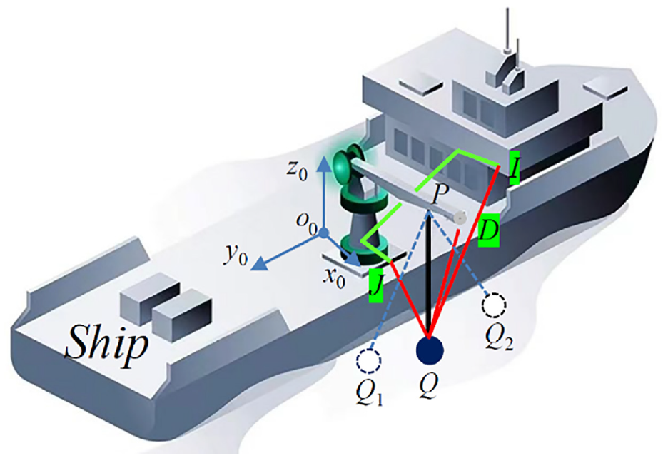
Model of shipboard crane system.
The o0x0y0z0 is the ship coordinate system. The three cables DQ, IQ, and JQ are connected to the anti-swing hydraulic motor in the base of the crane and connected to the hook by the pulley block. The anti-swing hydraulic motor controls the cable movement.
When the payload moves from Q to Q1 under external excitation, the anti-swing hydraulic motor connected with the cable JQ enters the active working state, so that the pulling force of the cable JQ becomes smaller. At the same time, the anti-swing hydraulic motor connected with the cable IQ and DQ enters the passive working state, so that the cable IQ and DQ maintain a large pulling force. In this way, the resultant force of the three cables is opposite to the motion direction of the payload, which consumes the energy of the payload swing and realizes the suppression of the payload swing.
Dynamic model of the payload system
The shipborne crane mainly has three movement forms: lifting, slewing, and luffing. When working at sea, the crane is affected by the roll, pitch, and heave of the ship, among which the roll has the greatest impact on the operation. Therefore, the three anti-swing limbs are installed on the main boom of the crane, and the movement of the main sling is followed by the three cables on the anti-swing limbs. The crane payload swing is restrained by controlling the working state of the three cables.
As shown in Figure 2, which is a simplified model of shipborne crane equipped with payload anti-swing device. The o-xyz is the geodetic coordinate system, the o0x0y0z0 is the geometric center coordinate system of the ship deck, the o1-x1y1z1 is the shipborne crane base coordinate system, the o2-x2y2z2 is the crane luffing coordinate system, and the o3-x3y3z3 is the boom tip coordinate system. The θ0x is the pitch angle of the ship, θ0y is the ship roll angle, θ1 is the slew angle of the crane, θ2 is the luffing angle of the crane. lo0o1 is the distance from the geometric center of the ship deck to the center of the crane base. lo1o2 is the distance from the center of the crane base to the center of the crane luffing coordinate system, in other words, lo1o2 is the height of the crane mast.
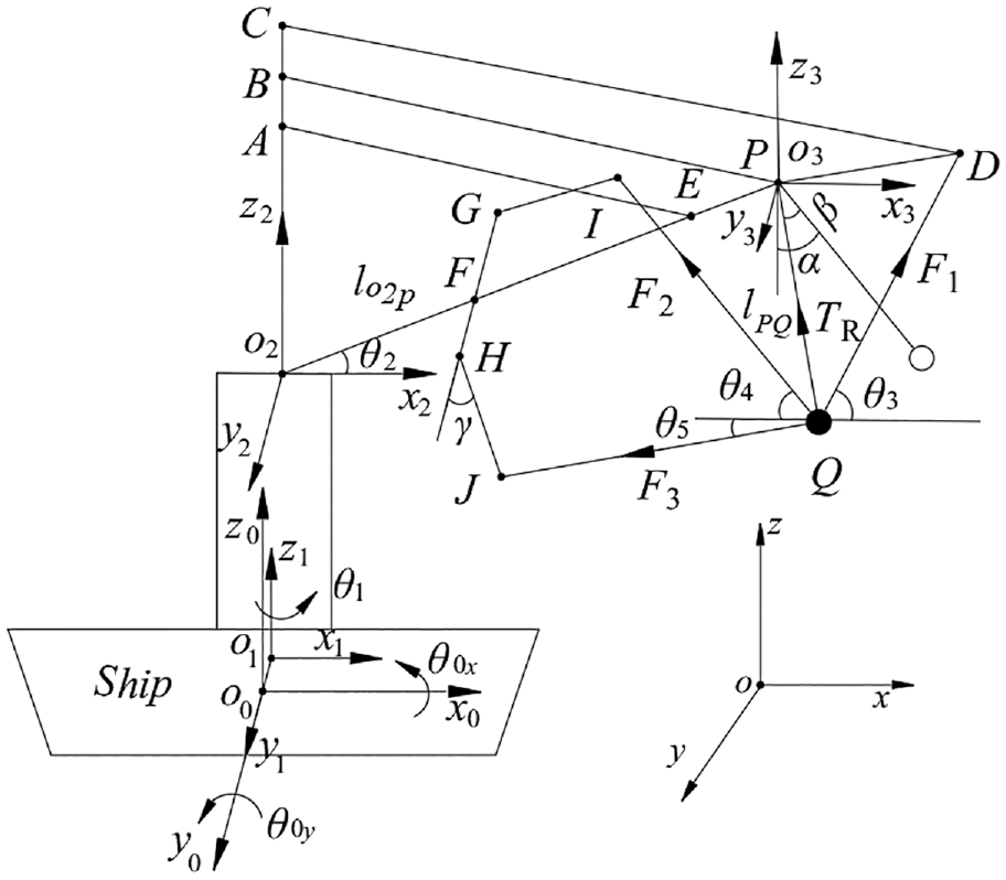
Simplified model of shipborne crane equipped with payload anti-swing device.
In Figure 2, O2P is the main boom, the main boom is located in plane x3o3z3, lo2p is the length of the main boom, PD, FGI, and FHJ are anti-swing limbs. Where the FH segment of the anti-swing limb is perpendicular to the main boom O2P, γ is the included angle between the GH and HJ segments of the anti-swing limb. AE is the luffing cable, and BPQ is the main sling. DQ, IQ, and JQ are the three cables, and their corresponding pulling force is F1, F2, and F3 respectively. Q is the payload, and lPQ is the length of the main sling.
According to robotics, define
Define
Define
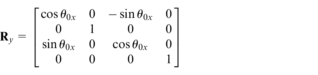
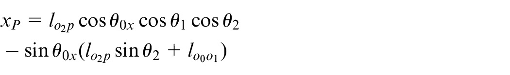
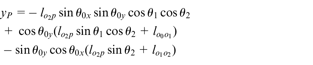
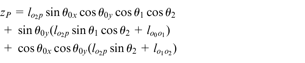
The conversion process of the point P from the o3-x3y3z3 coordinate system to the o-xyz inertial coordinate system is as follows:
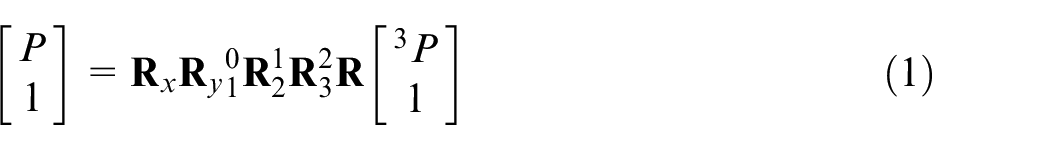
where:
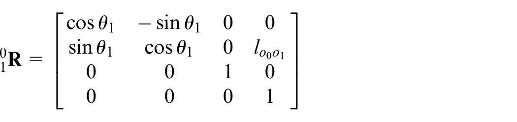
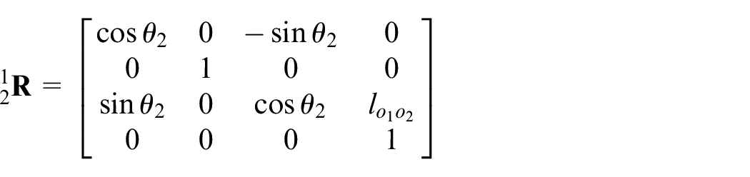
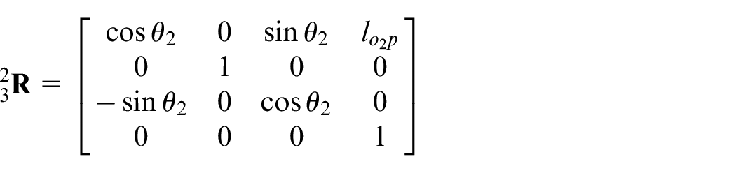
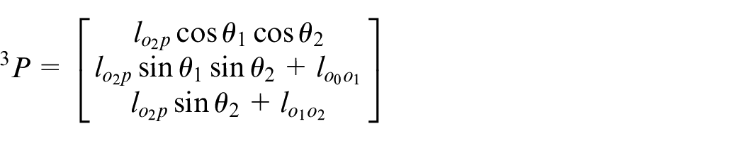
Finally, the position coordinates of point P in the inertial coordinate system o-xyz are obtained.
The in-plane angle α is the angle between the main sling and plane x3o3z3, and the out-of-plane angle β is the angle between the main sling and plane y3o3z3. In the simplified model of a shipborne crane equipped with payload anti-swing device, the components of the pulling force on the three cables DQ, IQ, and JQ on the x-axis are:
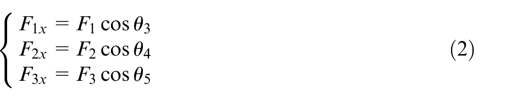
where θ3, θ4, and θ5 are the included angles of cable DQ, IQ, and JQ in the x-axis direction respectively, and their magnitudes are related to the position, the length of the anti-swing limb, and the length of the cable.
Only under the roll excitation in Figure 1, the cable IQ and JQ are symmetrically distributed in space and their pulling force is equal. Therefore, the resultant force fx of the pulling forces on the three cables in the x-axis direction can be expressed as:


At this time, in the direction of the in-plane angle, the payload anti-swing device is equivalent to using two cables to control the payload swing of the in-plane angle, which consumes the energy of the payload swing.
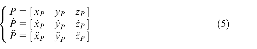
The coordinate of the crane boom point P is (xP, yP, zP) and the payload Q is (xQ, yQ, zQ) in coordinate system xoz. Then the position, the velocity, and acceleration of point P in space can be expressed as:
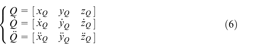
The position, the velocity, and acceleration of payload Q in space can be expressed as:
The kinetic energy of payload Q can be expressed as:
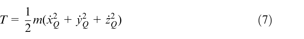
where T is the kinetic energy of the payload.
Setting the plane passing through the initial position point P of the crane boom and parallel to the plane x3o3y3 be the zero potential energy surface, then the potential energy of the payload system is:

where, V is the potential energy of the payload, and m is the mass of the payload.
Then the Lagrange operator of the payload system is:

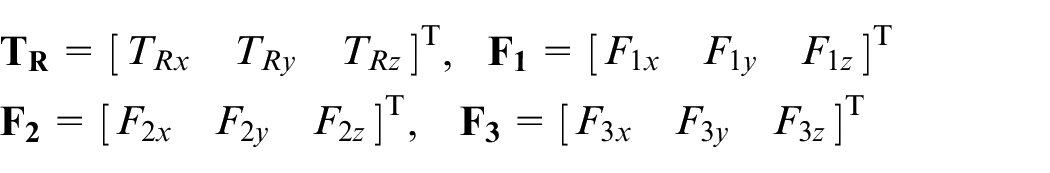
In the payload system, the in-plane angle α and the out-of-plane angle β are selected as generalized coordinates, then the resultant forces of the three cables on the generalized coordinates are respectively:
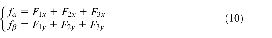
where, fα is the resultant force on generalized coordinates α, fβ is the resultant force on generalized coordinates β, F1x, F2x, and F3x are the component forces of the three cables in the x3 direction respectively; F1y, F2y, and F3y are the component forces of the three cables in the y3 direction respectively.
The dynamic equation of the payload system is obtained by the Lagrange method.
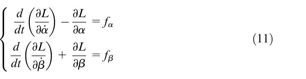
where,
By solving equation (11), the acceleration expressions for the in-plane and out-of-plane angles can be obtained.
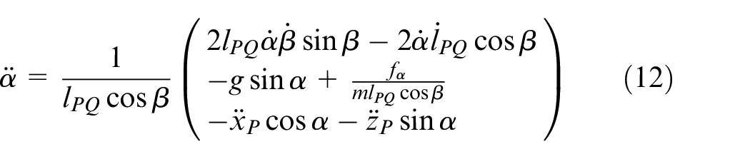
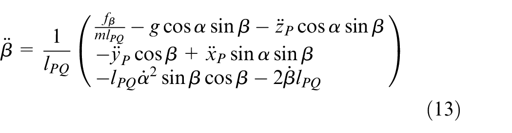
where,
Dynamic model of hydraulic system
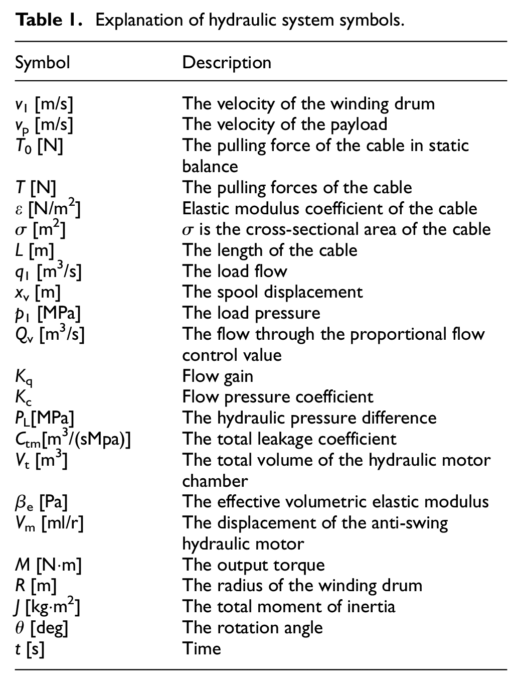
Some important Explanation of hydraulic system symbols are stored in Table 1.
Explanation of hydraulic system symbols.
The payload anti-swing system of shipborne crane uses a hydraulic pump to drive three anti-swing hydraulic motors. Figure 3 is the working principle of the anti-swing hydraulic motor system. The hydraulic oil from the anti-swing motor is pressurized by the hydraulic pump 1, passes through the unidirectional globe valve 2, passes through the proportional flow control valve 4 and the solenoid directional valve 5, and finally enters the anti-swing hydraulic motor 8. By controlling the valve opening of the proportional flow control valve 4 and the spool working position of the solenoid directional valve 5, the upper computer controls the movement of the three cables by adjusting the velocity and steering of the anti-swing hydraulic motor.
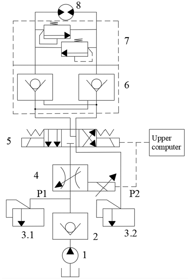
The working principle of the anti-swing hydraulic motor system.
The constant tension control payload anti-swing method is applied to the motion control of the crane payload. When the shipborne crane is working at sea, the three cables follow the movement of the main sling, the payload produces random swing in space due to the ship’s motion excitations, the wind disturbance, and the movement of the crane itself, which makes the payload swing have complex dynamic response characteristics.
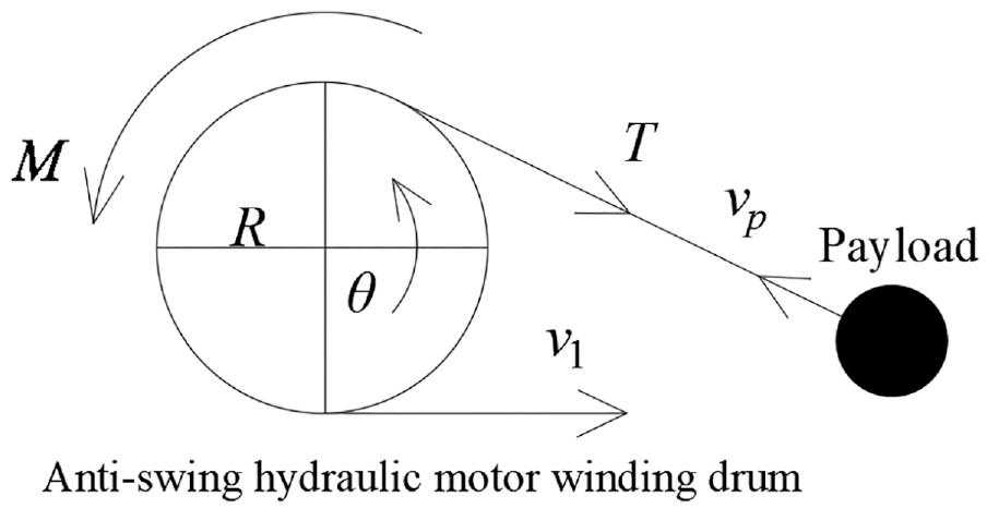
To simplify the modeling process, this paper ignores wind disturbance. It is assumed that the payload velocity direction is always collinear with the cable, and the cable tension is in one-to-one correspondence with the strain of the cable. The torsion and bending of the cable are ignored. Figure 4 is a schematic diagram of the anti-swing hydraulic motor in the passive working state.
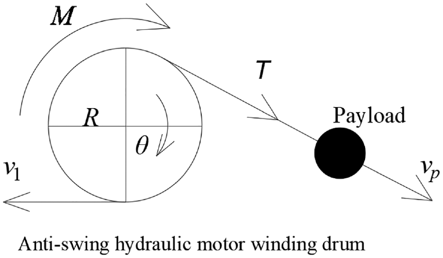
The anti-swing hydraulic motor in the passive working state.
In Figure 4, the velocity of the winding drum is v1, and the movement velocity of the payload is vp. When v1 < vp, the cable is stretched and the stretching amount increases gradually, which means that the pulling force of the cable increases gradually. When v1 > vp, the stretching amount of the cable gradually decreases, and the pulling force of the cable gradually decreases. In other words, the change of the relative velocity between the winding drum and the payload directly affects the elongation of the cable, and the elongation change of the cable directly affects the tension change of the cable.
When the anti-swing hydraulic motor enters the passive working state, in order to ensure the anti-swing effect of the payload and maintain the tension of the cable, it is necessary to control the winding drum velocity to be less than the payload velocity. In this way, the power demand of the hydraulic system is smaller, the working pressure of the hydraulic system output is smaller, the compressibility of the hydraulic oil is not obvious, and the possibility of hydraulic oil leakage is also reduced. Therefore, the leakage and compressibility of the hydraulic oil can be ignored.
According to Hooke’s law, the pulling force of the cable on the winding drum can be expressed as:
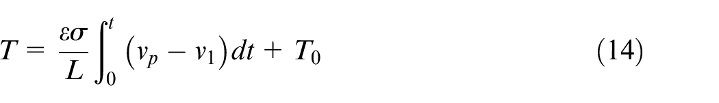
T 0 is the pulling force of the cable when the payload is in static balance, ε is the elastic modulus coefficient of the cable, σ is the cross-sectional area of the cable, L is the length of the cable, t is the time.
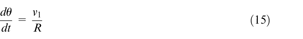
The linear velocity of the anti-swing hydraulic motor winding drum in the passive working state:
The anti-swing hydraulic motor system belongs to the valve-controlled hydraulic motor speed control system. Due to the compressibility of hydraulic oil and sealing of valve parts, the pressure and flow in the actual hydraulic valve are a nonlinear relationship. In this paper, the nonlinear relationship between the load flow q1, load pressures p1, and the spool displacement xv of the proportional flow control valve in the hydraulic motor system is expressed by the formula (16).

In the dynamic analysis of the flow equation of the proportional flow control valve, equation (16) is first linearized by using the linearization theory. The working range of the proportional flow control valve is limited to a specific working point
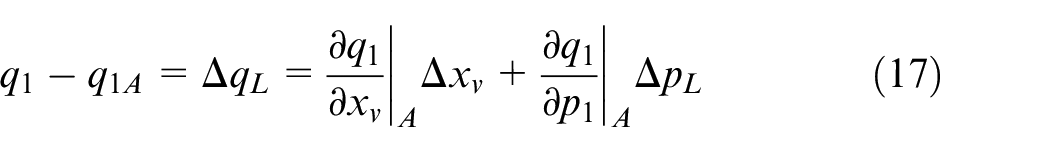
Finally, the linearized flow equation of the proportional flow control valve is obtained.

where Qv is the flow through the proportional flow control valve, Kq is flow gain, Kc is the flow pressure coefficient, and PL is the hydraulic pressure difference between the two chambers of the anti-swing hydraulic motor winding drum.
According to the continuity equation of hydraulic motor flow, the flow equation of an anti-swing hydraulic motor in a passive working state is:
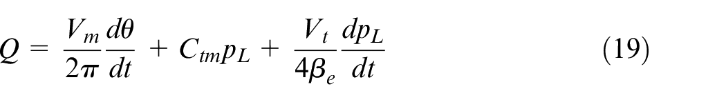
where Ctm is the total leakage coefficient of the anti-swing hydraulic motor, Vt is the total volume of the hydraulic motor chamber, and βe is the effective volumetric elastic modulus.
In the passive working state, the output torque of the anti-swing hydraulic motor winding drum is:
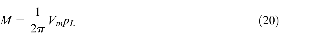
where Vm is the displacement of the anti-swing hydraulic motor.
When the anti-swing hydraulic motor winding drum in the passive working state, according to Newton’s second law, at any time, the output torque M of the winding drum and the torque TR generated by the cable pull are in the same direction, and they work together, which is shown in the rotation angle θ of the anti-swing hydraulic motor winding drum is constantly changing. Therefore, we obtain the torque balance equation:
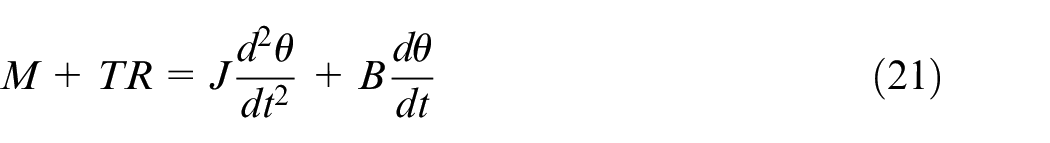
where M is the output torque, T is the pulling forces of the cable, R is the radius of the anti-swing hydraulic motor winding drum, J is the total moment of inertia, θ is the rotation angle, and B is the viscous damping coefficient.
Figure 5 is a schematic diagram of the anti-swing hydraulic motor in the active working state. Similarly, When the anti-swing hydraulic motor winding drum in the active working state, we obtain the torque balance equation:

The anti-swing hydraulic motor in the active working state.
Constant tension control
Transfer function of hydraulic system
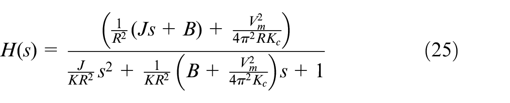
According to the dynamic model of the hydraulic system, the transfer function model of the system is established. When the anti-swing hydraulic motor is in the passive working state, the leakage of the hydraulic system and compressibility of the hydraulic oil are ignored. The Laplace transform is performed on equation (21) and the transfer function relationship between the cable tension and the proportional flow control valve opening is obtained.

where the G(s) and H(s) are transfer functions respectively, and “−” represents the movement direction of the proportional flow control valve spool.
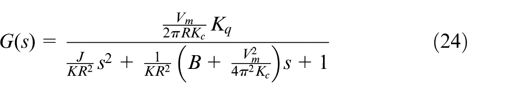
It can be seen from the transfer function that when the anti-swing hydraulic motor is in the passive working state, the proportional flow control valve opening increases, the linear velocity of the ν1 increases, the velocity difference between ν1 and νp decreases, and the pulling force of cable decreases. When the velocity of the νp increases, the difference between the ν1 and νp increases, and the pulling force of the cable increases. Therefore, by controlling the proportional flow control valve opening, the velocity difference between the ν1 and νp can be controlled, and finally, the pulling force of the cable can be controlled.
The same method can be used to obtain the transfer function between the anti-swing hydraulic motor winding drum and proportional flow control valve opening in the active working state.

It can be seen from the transfer function that when the anti-swing hydraulic motor winding drum is in the active working state, the proportional flow control valve opening increases, the linear velocity of the ν1 increases, the velocity difference between the ν1 and νp increases, and the pulling force of cable increases. When the velocity of the νp increases, the difference between ν1 and νp decreases, and the pulling force of the cable decreases. Therefore, by controlling the proportional flow control valve opening, the velocity difference between the ν1 and νp can be controlled, and finally, the pulling force of the cable can be controlled.
Therefore, equations (23) and (26) can be uniformly expressed as:

where “+” represents the transfer function model of the anti-swing hydraulic motor winding drum in the passive working state; “−” represents the transfer function model of the anti-swing hydraulic motor winding drum in the active working state.
Constant tension control logic
The PID control module is added to the tension output control process of the constant tension control anti-swing device. By adjusting the opening, the PID control module adjusts the output velocity of the anti-swing hydraulic motor, which can ensure the control accuracy when the system parameters and load change. Figure 6 is the constant tension control block diagram. Tsi (Ts1, Ts2, and Ts3) is the tension setting value of the three cables, and Ti (T1, T2, and T3) is the actual tension output value of the three cables. Before the anti-swing device works normally, the upper computer sets the target tension value of the cable. The sensor is a feedback element, which converts the collected cable tension signals into digital signals and sends them to the upper computer. When there is a difference between the set tension value of the cables and the actual tension value, the upper computer will control the rotation direction and flow of the hydraulic motor. Then the velocity difference between ν1 and νp changes, which is benefic to adjust the cable’s tension. In this way, the constant tension control is realized.
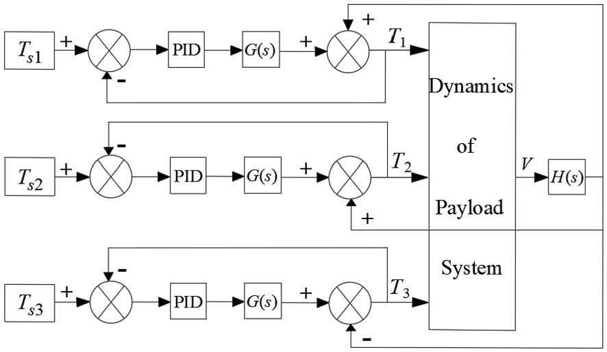
Constant tension control block diagram.
Therefore, when the anti-swing device works, there are always two cables in the strong tension state, and one cable in the small tension state. When the anti-swing hydraulic motor is in the passive working state, the payload velocity is used as a positive interference input system. When the anti-swing hydraulic motor is in the active working state, the payload velocity is used as a negative interference input system. Therefore, by controlling the velocity difference between the ν1 and νp, the pulling force of cables can be controlled.
Constant tension setting logic of the cables
For the constant tension anti-swing device, the quality of the constant tension control directly determines the anti-swing effect. Therefore, the setting method of constant tension in simulation and experiment is very important. When the payload system is in static equilibrium, the pulling force of the three cables and the main sling must first satisfy the static equilibrium relationship. Secondly, it should be considered that the three cables are used to restrain the payload swing during payload motion. Thus, it means that the direction of resultant force should be opposite to the direction of payload motion. Considering the lag and inertia of the hydraulic system, the tension threshold should be introduced to set the constant tension of the cables. The movement of the payload is controlled by the valve-controlled hydraulic motor.
Therefore, we make the following regulations for the pulling force on the cables.
The pulling force of cable DQ, IQ, and JQ are F1, F2, and F3 respectively, and the pulling force of main sling PQ is TR.

where F1, F2, and F3 are the tension setting value of cable DQ, IQ, and JQ, and δ1, δ2, and δ3 are tension thresholds of cable DQ, IQ, and JQ.
In simulation and experiment, the constant tension of the cable is set according to equation (28).
Dynamic simulation
This paper focuses on the study of shipborne crane payload swing during the work. As shown in Figure 1, the main boom is perpendicular to the central axis of the ship. The ship generates rolling motion under the external excitation, so the payload system of the shipborne crane makes pitch motion. When the payload is during the pitching motion, the pulling forces of IQ and JQ cable are F2 and F3 respectively. Since they are symmetrical and equal in space, F2 is used uniformly to represent them in the simulation.
Dynamic simulation of small and medium-sized cranes
The simulation parameters for small and medium-sized shipborne cranes under pitch excitation are shown in Table 2.
Simulation parameters of small and medium-sized shipborne cranes.
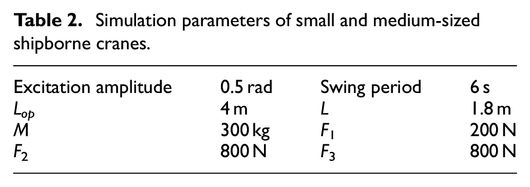
where the excitation amplitude is 0.5 rad, the swing period is 6 s, the length of crane boom is Lop, the length of main sling is L, and the weight of payload is m.
Figure 7 shows the comparison of the in-plane angle response of the payload system with and without the anti-swing device. Figure 8 shows the partial enlargement of the cable tension.
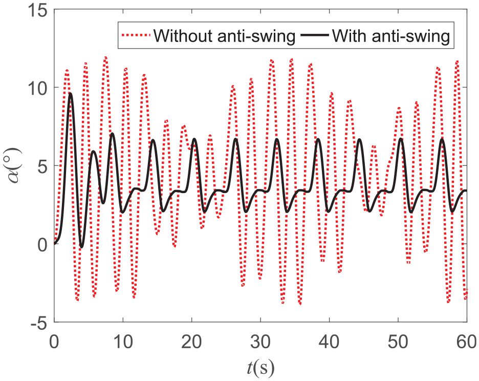
In-plane angle simulation comparison of small or medium-sized crane.
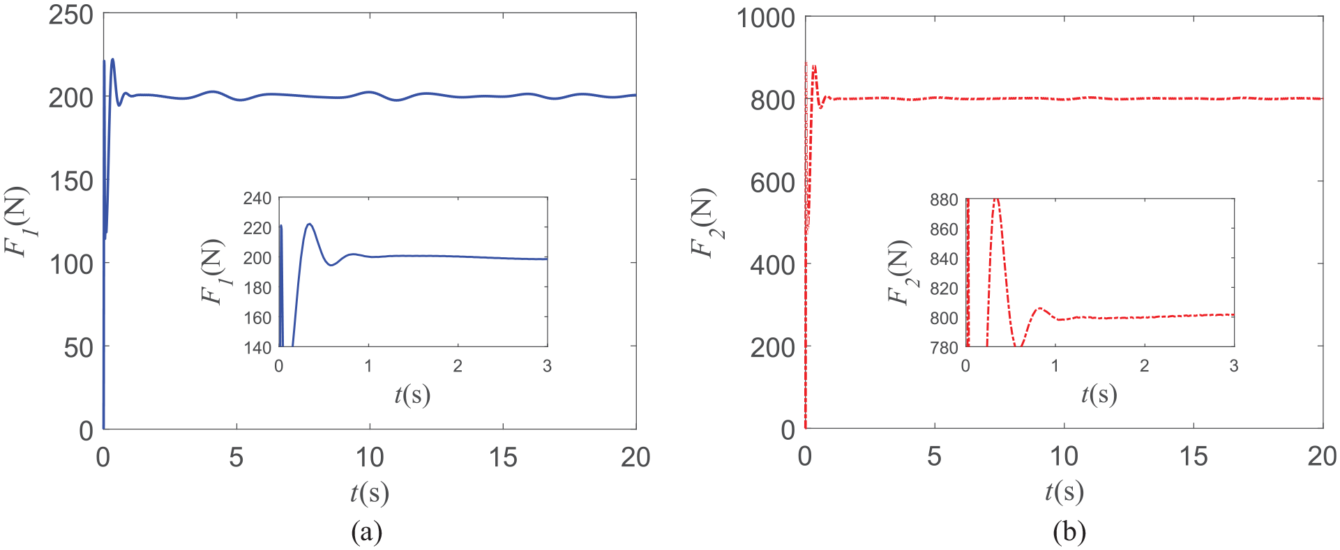
Partial enlargement of cable tension: (a) cable DQ tension and (b) cable IQ and JQ tension.
It can be seen from Figure 7 that when there is no the payload anti-swing device, the in-plane angle swing period of the payload under the external excitation is 6 s, the maximum positive swing angle is 12.5°, and the maximum negative swing angle is close to 4°. In other words, the positive swing amplitude is about three times the negative swing amplitude, and it is obvious that an asymmetric swing has occurred.
In the simulation, setting the cable tension is as follows: firstly, based on the asymmetric swing amplitude of the payload in space, and then combined with simulation results and dynamic response of the payload dynamic model. Finally, according to equation (28), the pulling force of the cable DQ is set to F1 = 200 N, and the symmetrical cable IQ and JQ are set to F2 = F3 = 800 N.
It can be seen from Figure 7, that under the action of the payload anti-swing device, the maximum amplitude of the payload in-plane angle is 7°, the effect of anti-swing can reach 73%, and the swing period is 6 s, which can follow the external swing period. In other words, the payload takes 6 s to reach a stable state.
It can be seen from Figure 8, that it only takes 1 s for the cable tension to stabilize at the set value, and the cable tension does not fluctuate with the payload swing. It means that the payload anti-swing device has fast anti-swing response-ability and good dynamic stability characteristics.
Dynamic simulation of large-sized crane
The simulation parameters for large-sized shipborne crane under pitch excitation are shown in Table 3.
Simulation parameters of large-sized shipborne crane.
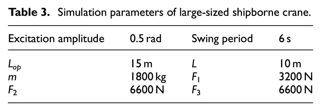
where the excitation amplitude is 0.5 rad, the swing period is 6 s, the length of crane boom is Lop, the length of main sling is L, and the weight of payload is m.
Figure 9 shows the in-plane angle response of the payload system with and without the anti-swing device, and Figure 10 shows the partial enlargement of the cable tension.
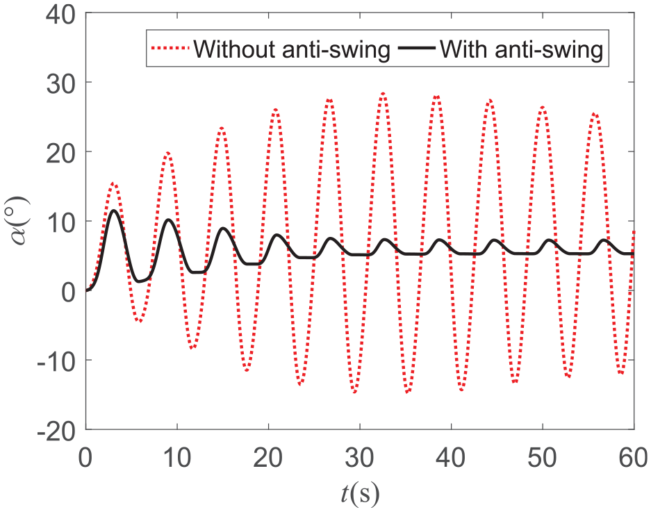
In-plane angle simulation comparison of large-sized crane.
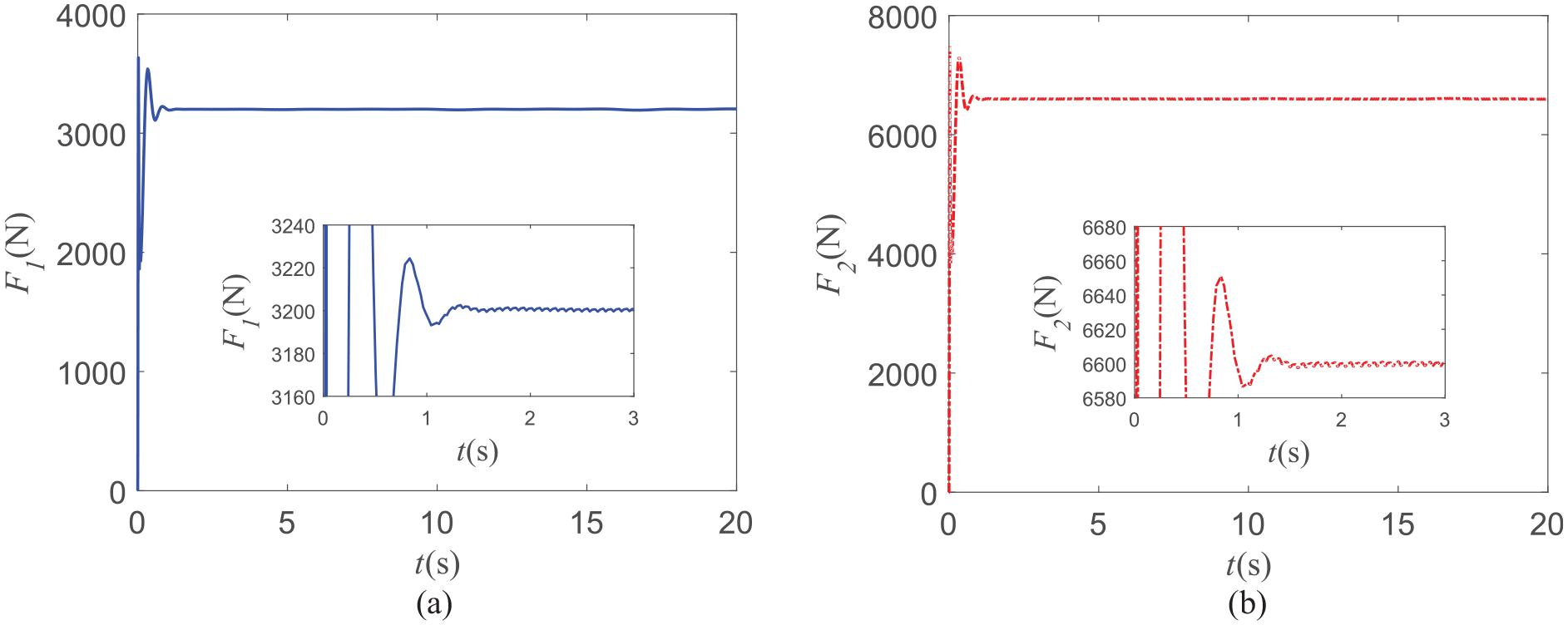
Partial enlargement of cable tension: (a) cable DQ tension and (b) cable IQ and JQ tension.
It can be seen from Figure 9 that when there is no payload anti-swing device, the in-plane angle swing period of the payload under the action of external excitation is 6 s, the maximum positive swing angle is close to 30°, and the maximum negative swing angle is 15°. In other words, the positive swing amplitude is about twice that of the negative swing amplitude, and it is also obvious that an asymmetric swing has occurred.
In the simulation, setting the cable tension is as follows: firstly, based on the asymmetric swing amplitude of the payload in space, and then combined with simulation results and dynamic response of the payload dynamic model. Finally, according to equation (28), the pulling force of the cable DQ is set to F1 = 3200 N, and the symmetrical cable IQ and JQ are set to F2 = F3 = 6600 N.
It can be seen from Figure 9, that under the action of the payload anti-swing device, the in-plane angle of the payload is stable at about 6° after the 20 s, the effect of payload anti-swing is close to 80%, the swing angle fluctuation of the payload is less than 2°, which meets the operational requirements of the shipborne crane.
It can be seen from Figure 10, that it only takes 2 s for the cable tension to stabilize at the set value. In general, the cable tension fluctuation is small and the stability speed is fast, and the in-plane angle of the payload is gradually stabilized. It means that the payload swing is well controlled.
Compared with paper 7, the payload anti-swing method proposed in this paper has faster response and better anti-swing effect. Moreover, in the simulation of payload anti-swing of shipborne crane, we consider the influence of hydraulic system on the anti-swing effect of the payload, and find the phenomenon of asymmetric swing of the payload. The simulation results show that the method proposed in this paper is suitable for small and medium-sized crane and large-sized crane.
Experiment validation
Experiment device
The dynamic simulation and experiment comparison of the payload swing under the ship rolling excitation are carried out. Similarly, the crane boom is perpendicular to the central axis of the ship. The ship generates rolling motion under the external excitation, so the payload makes pitch motion. The payload anti-swing device of the shipborne crane is shown in Figure 11, which is mainly composed of six degrees of freedom (6-DOF) ship motion platform, hydraulic station, crane, electrical control cabinet, and upper computer. The 6-DOF ship motion platform is used to imitate the ship motion under the excitation of sea waves; the hydraulic station provides power for the hydraulic system of the anti-swing device.
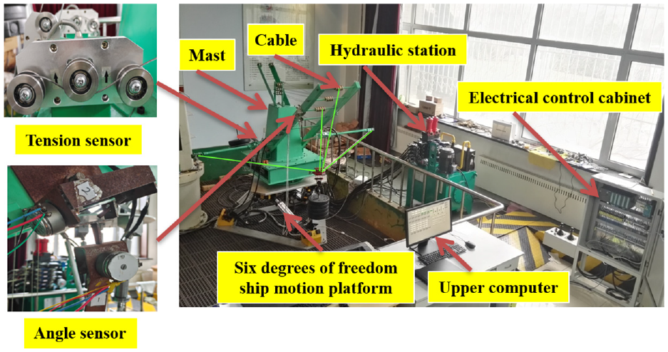
Anti-swing device of shipborne crane.
As shown in Figure 11, the angle sensor is installed on the main boom of the crane, which is used to measure the changes of the in-plane angle and the out-of-plane angle of the payload under environmental excitation. Tension sensors are arranged behind the crane mast to measure the tension changes of the three cables. The angle sensor collects the swing signal of the crane payload and transmits it to the upper computer through the electric control cabinet. The tension sensor transmits the tension signal of the cables back to the upper computer through the electric control cabinet. According to these signals, the upper computer outputs control commands to control the hydraulic motor of the hydraulic station and adjust the working status to realize the control of the crane payload swing.
Comparison of in-plane angle
The experiment and simulation parameters are set as follows: the amplitude of ship roll excitation is 10°, the period is 6 s, the length of the main boom Lop = 1.7 m, the main sling L = 1 m, and the weight of payload m = 25 kg. In the experiment, the tension setting value of the cable DQ is F1 = 10.5 N, and the tension setting value of the cable IQ and JQ are F2 = F3. In the simulation, the tension setting value of the symmetric cable is F2 = F3 = 12.5 N. Figures 12 and 13. show the comparison of in-plane angles with the anti-swing device under experiment and simulation conditions.
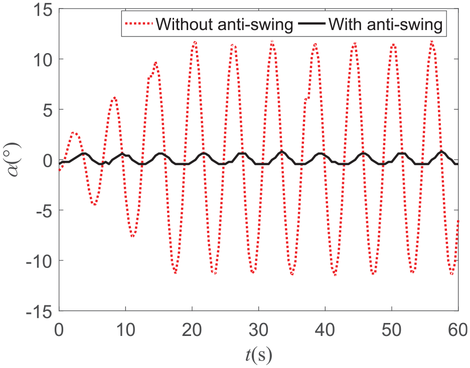
Comparison of in-plane angle experiment.
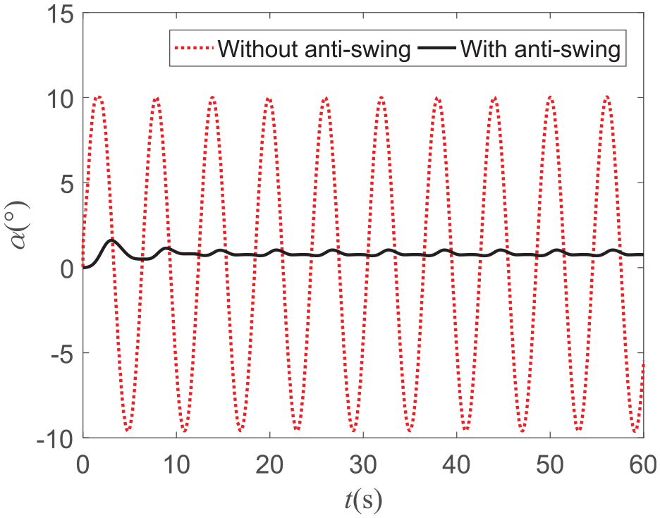
Comparison of in-plane angle simulation.
It can be seen from Figure 12 that during the experiment without the anti-swing device, the payload makes a quasi-sinusoidal motion with a period of 6 s, and the maximum amplitude is 12.5°. It shows that under the experimental conditions, the swing period of the payload follows the excitation period of the ship, but the amplitude of the swing angle is slightly larger than the excitation amplitude of the ship. After the installation of the anti-swing device, payload makes the quasi-sinusoidal motion with a period of 6 s, and the maximum amplitude is 1.8°, the payload anti-swing effect is close to 85.6%. However, the payload in-plane angle is reduced by 70% in the telescopic sleeve anti-swing scheme. 7 The anti-swing effect is obvious, which shows that the shipborne crane with the anti-swing device can suppress the external load disturbance and make the shipborne crane operation more stable and efficient.
It can be seen from Figure 13 that during the simulation without the anti-swing device, the payload makes a quasi-sinusoidal motion, the motion period is 6 s, the maximum amplitude is 10°, and the positive swing amplitude is slightly greater than the negative swing amplitude. It means that the amplitude of the payload swing angle under the simulation environment will be slightly larger than the excitation of the ship, and there is a payload asymmetric swing phenomenon. The simulation is carried out with the anti-swing device. When the in-plane angle is stable, the period of payload motion is 6 s and the maximum amplitude is 1.9°. The payload swing angle gradually decreases under the pulling force of the cables, and finally progressively stabilizes at about 1°.
Comparing the in-plane angles simulation and experiment with or without an anti-swing device under the same parameter conditions, it can be found that the simulation and experiment results show that the payload swing angle amplitude will be greater than the ship excitation amplitude, and the payload swing angle can be stabilized around 0°, the anti-swing effect is obvious. But they are slightly different, the payload appears to asymmetric swing in the simulation, and finally, the payload swing is stable at around 1°. When the in-plane angle of the payload is stable in the experiment environment, the amplitude of the payload swing angle is 1.8°. In the simulation analysis of the payload system dynamics, due to the spatial symmetry of the cables, it is considered that the pulling forces of the cable IQ and JQ are equal, and the pulling force of each cable only acts on the payload swing, just the tension setting values are different. Therefore, when the payload swing angle is stable, the payload asymmetric swing will occur.
The experiment and simulation results of the out-of-plane angle of the shipborne crane payload are shown in Figure 14. It can be seen from the experiment that the payload out-of-plane angle is stable from 0.7° at the beginning to 0.16°, and finally remains near 0.06°, the anti-swing effect of the payload out-of-plane angle is between 77.1% and 91.4%. In the simulation, the payload out-of-plane angle changes from 0.2° to close to 0°, and the swing suppression of the out-of-plane angle is realized in 28 s. As you can see, when the payload reaches the equilibrium position, the payload out-of-plane angle is not 0°. In other words, the payload occurs asymmetrical swing phenomenon.
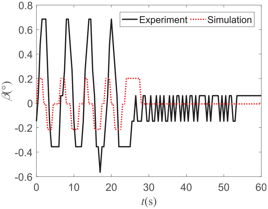
Comparison of out-of-plane angle.
In the experiment, the three cables are spatial symmetry, and the three cables work together to restrain the payload swing in all directions. Therefore, the payload swinging angle is more stable, the payload asymmetric swing is not easy to occur, which also proves the superior performance of the payload anti-swing device in payload anti-swing.
In this paper, the anti-swing effect of the payload out-of-plane angle is 77.1% to 91.4%, which is slightly lower than that of paper 36, where the payload out-of-plane angle is reduced by more than 90%. However, considering the influence of the hydraulic system on the payload anti-swing in this paper, thus the payload anti-swing effect is acceptable, which also proves that the control method proposed in this paper has certain superiority.
Comparison pulling force of the cable
The payload swing angle will fluctuate in a small range under both the experiment and simulation; it means that the pulling force of the cable also fluctuates. Figures 15 and 16. are schematic diagrams of the pulling force of cables DQ and JQ in experiment and simulation respectively.
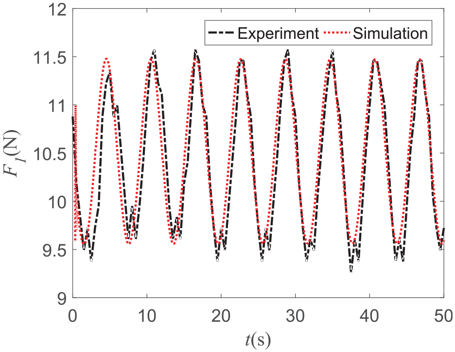
The pulling force of the cable DQ.
The pulling force of cable JQ.
Figure 15 shows the comparison between simulation and experiment of cable DQ’s pulling force F1, when the pulling force setting value is 10.5 N, it can be seen that the pulling force of the cable fluctuates around 10.5 N. The amplitude of fluctuation is almost the same; the period is 6 s and the payload motion trend is the alike, which proves the accuracy of the simulation model. The change time of pulling force value from a wave peak to wave trough is 3 s, which means that the tension fluctuates greatly when the motion direction of the payload changes.
When the movement direction of the payload changes in the experiment, the pulling force of the cables change slowly, and the changing trend is not as smooth as the pulling force curve in the simulation. That’s mainly because it takes time to change the direction of the hydraulic valve and the hydraulic motor in the experiment. Therefore, when the hydraulic valve changes direction and the pressure of the hydraulic system changes, the tension will fluctuate. In the simulation, the change of pulling force is relatively smooth because the reversing time of hydraulic valve parts and the compressibility of hydraulic oil are ignored.
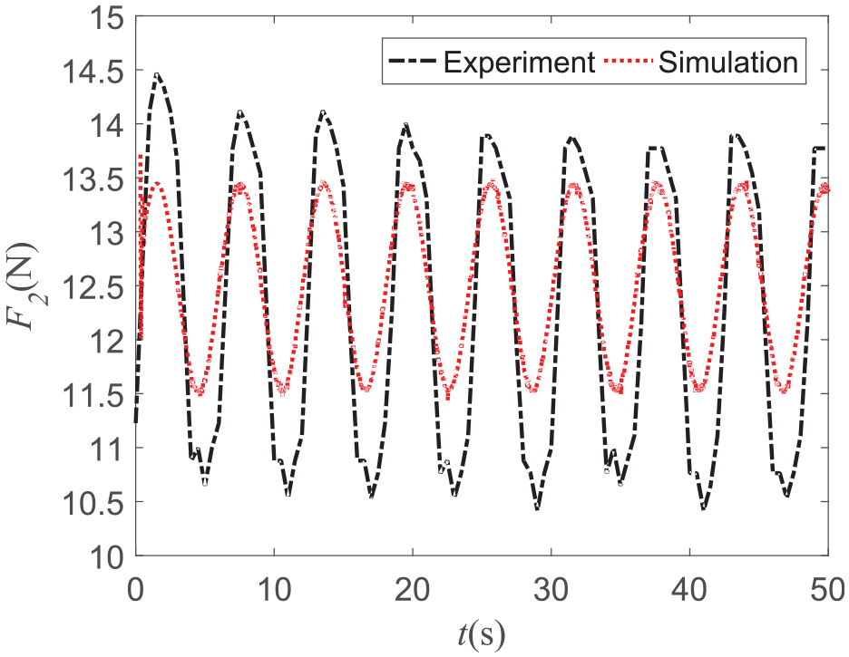
Figure 16 shows the comparison of the cable JQ’s pulling force between the experiment and the simulation. The pulling force value is uniformly recorded as F2, and the setting value is 12.5 N. The pulling force fluctuation trend of the simulation and the experiment is the same, and both can stabilize near the setting value with a period of 6 s, which can follow the ship’s excitation motion.
In the experiment, the cables are arranged in a triangle in space, and the pulling force of the cables acts on both the in-plane and out-of-plane angles. In the simulation, the crane payload makes pitch motion, so the anti-swing effect of spatially symmetrical cable IQ and JQ is equivalent to the anti-swing effect produced by one cable, and the maximum value of pulling force fluctuation in the simulation is slightly smaller than that in the experiment.
Asymmetric swing experiment
Aiming at the problem of payload asymmetrical swing in simulation and experiment, the payload asymmetric swing experiment is carried out on the anti-swing device of the shipborne crane. Figure 17 is a schematic diagram of payload skew pulling, and it shows the control effect of the anti-swing device on the payload asymmetrical swing under the action of the disturbance force Fd.
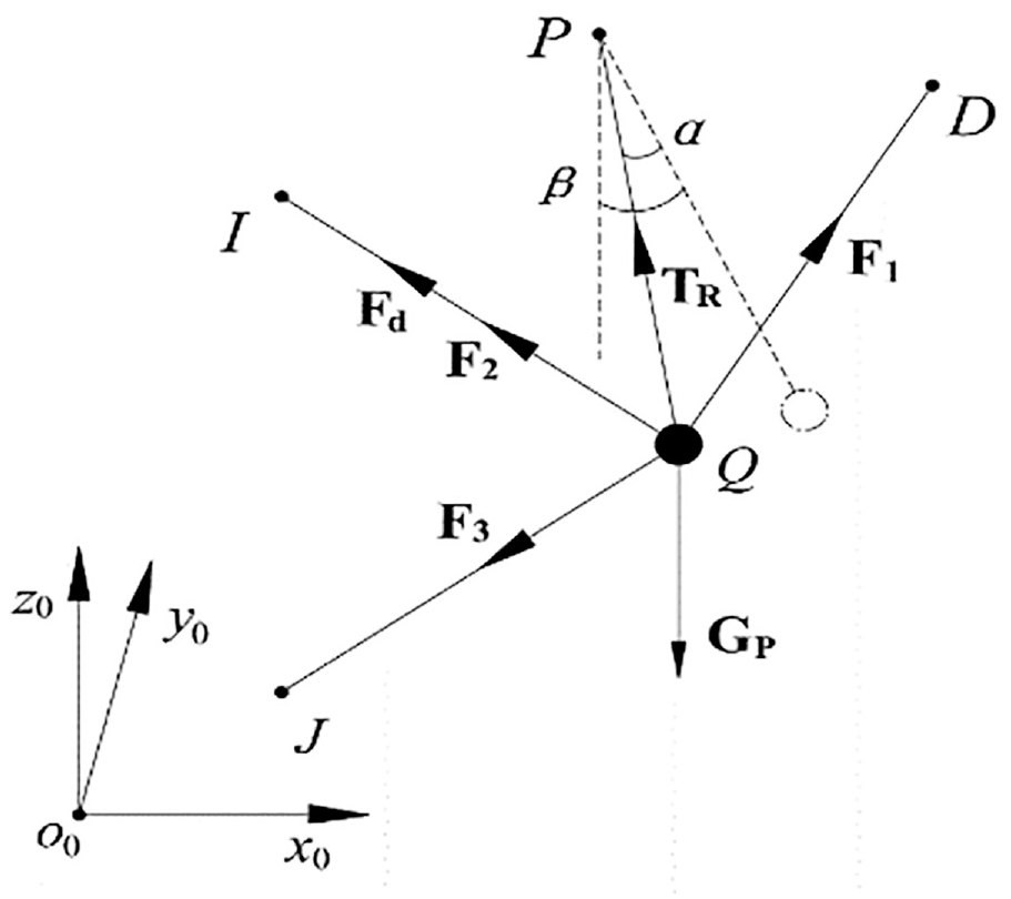
Schematic diagram of payload skew pulling.
Figure 18 shows the changes of tension F1, F2, and F3 on three cables DQ, IQ, and JQ. When the disturbance force Fd is applied to the cable IQ, the payload will appear an asymmetrical swing phenomenon. When the disturbance force Fd becomes 0, under the action of the anti-swing hydraulic motor, the pulling force F3 of the cable JQ increases, and finally the payload Q is pulled back to the equilibrium position. Due to the payload swing, the pulling force F1 of the cable DQ also changes all the time, which causes the cable to vibrate.
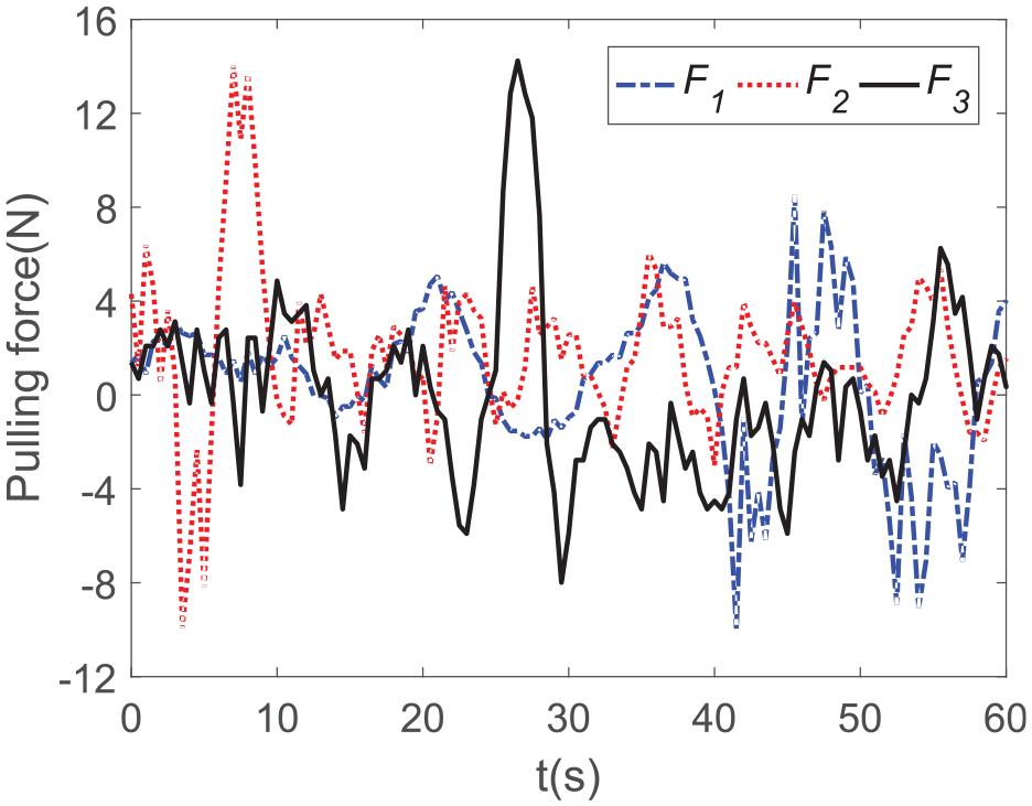
Tension changes of the three cables.
The angle sensor installs on the crane test bench and transmits the change data of the in-plane angle and the out-of-plane angle of the payload to the upper computer. Figure 19 shows the swing angle changes of the payload in the asymmetric swing experiment.
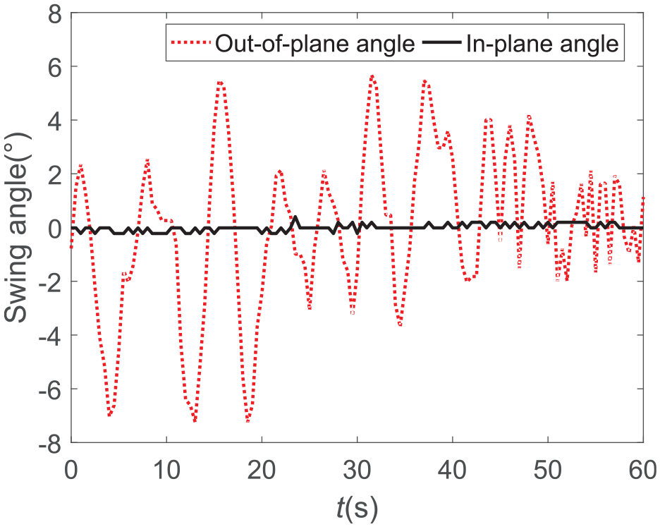
The swing angle changes of the payload.
It can be seen from Figure 19 that under the experimental conditions, the out-of-plane angle of the payload increases with the increase of the pulling force F2, and the maximum reaches 7.5°. Under the action of F3, the maximum out-of-plane angle of the payload becomes 5.5°. Under the action of F1, the out-of-plane angle of the payload begins to flatten. Finally, under the combined action of the three cable IQ, JQ, and DQ, the out-of-plane angle of the payload fluctuates from 0° to 2° and tends to 0°. The change of the in-plane angle of the payload is relatively gentle, and when F1 acts, it fluctuates. At the same time, the maximum is no more than 0.5°, and the final is 0°. In this experiment, the control ability of the anti-swing device to the asymmetrical swing of the payload is 73.3%.
To understand the influence of payload asymmetric swing on the output oil pressure of the hydraulic pump port, we simulated the hydraulic system in Figure 3. The output oil pressure curve of hydraulic pump 1 under the payload asymmetric swing is obtained. In the payload asymmetric swing experiment, the pressure change signal of the hydraulic oil is transmitted to the upper computer by the pressure sensor, and the oil pressure change curve of the hydraulic pump port is obtained. As shown in Figure 20.
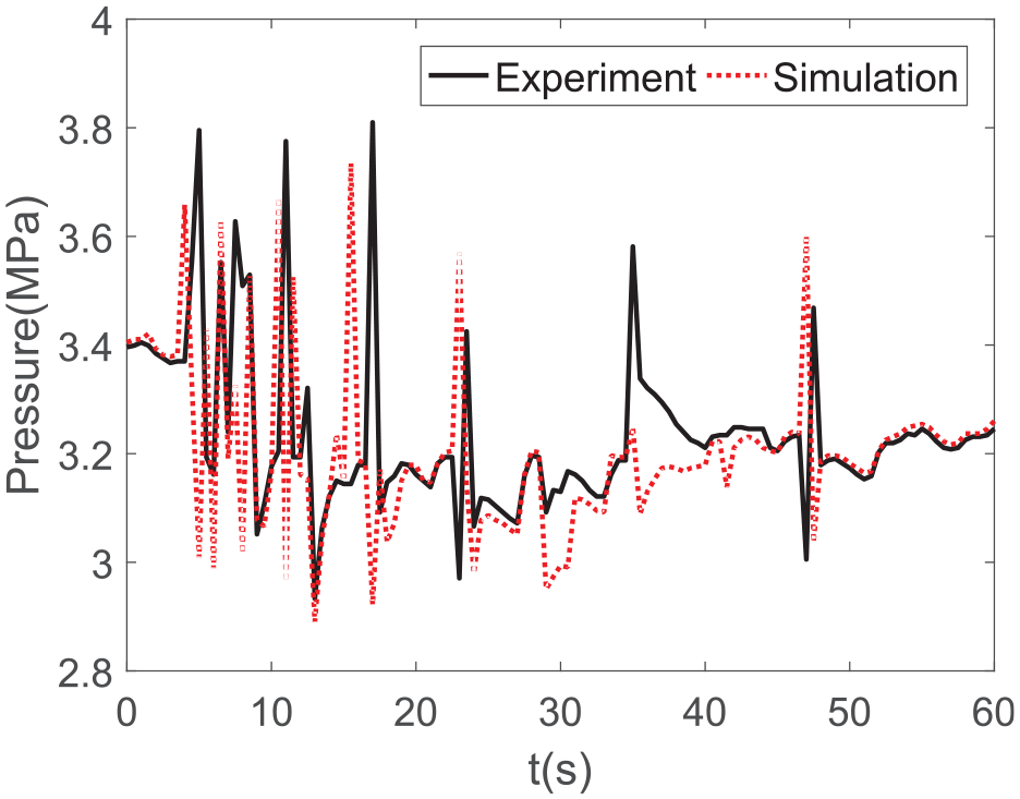
The oil pressure change curve of the hydraulic pump port.
It can be seen from Figure 20 that the oil pressure of the hydraulic pump port fluctuates between 2.9 and 3.8 MPa in the experiment and between 2.9 and 3.75 MPa in the simulation. The oil pressure is relatively stable without large fluctuations, which is mainly due to the small mass of the payload in the experiment. In addition, the inherent delay of the hydraulic system and the compressibility of the hydraulic oil can also affect the output oil pressure of the hydraulic pump port.
The simulation and experimental results show that the anti-swing device in this paper has a good restraining effect on the payload asymmetric swing.
Conclusions
In this paper, the dynamic model of the payload system of the shipborne crane equipped with three anti-swing cables is established by the Lagrange method, and the differential equation of the swing angle of the payload under the ship’s roll excitation is obtained. Based on the principle of linear velocity feedback, the dynamic equations are built to describe the relation between the hydraulic winch and the payload. Some other findings are as follows:
The joint modeling of the shipborne crane payload motion and the hydraulic drive winch is realized. And a constant tension control method for the payload anti-swing of the hydraulic driven is proposed.
The simulation results show that the constant tension control can effectively suppress the payload swing of small and medium-sized cranes, and the effect of payload anti-swing can reach 73%; and the swing suppression effect of large-sized cranes is up to 80%. The experimental results show that the proposed method suppresses the payload swing by 85.6%.
It is the first time to find and study the problem of the payload asymmetrical swing of the shipborne crane. The experiment shows that the suppressing effect of the payload asymmetrical swing is up to 73.3%. The simulation and experimental results strongly verify the reliability of the payload anti-swing technology proposed in this paper.
In the future, we will consider the influence of the eccentric torque generated by the shipborne crane boom at the excitation center of the ship on the payload anti-swing. Further, in order to improve the improve the anti-swing performance of the shipborne crane payload system in various environments, we will continue to optimize the mechanical structure design of the test bench, improve the output characteristics of the hydraulic pump, optimize the constant tension model, and consider more factors that affect the payload anti-swing.
Footnotes
Declaration of conflicting interests
The author(s) declared no potential conflicts of interest with respect to the research, authorship, and/or publication of this article.
Funding
The author(s) disclosed receipt of the following financial support for the research, authorship, and/or publication of this article: this work was supported by the National Natural Science Foundation of China (Project No. 52101396), and the China Fundamental Research Funds for the Central Universities (No. 3132022207).