
Abstract
Look-up tables or semi-physical models are used in engine control application to enhance the transient control performance. However, the calibration of these look-up tables and/or semi-physical models is highly data dependent, requires significant calibration effort, and does not account for effects such as hardware aging, drifts, fuel variations, etc. To address these challenges, this paper presents a generic adaptive control concept for real-time engine control applications. The boundary conditions for the operation on a state-of-the-art engine control unit (ECU) are considered and Radial Basis Function (RBF)-based neural networks are identified for the approximation of non-linear models. To ensure optimal convergence and un-susceptibility to signal noise, a Kalman filter (KF) is exploited for training the RBF network and a modified approximation is derived in this work. The derived KF approximation shows ∼30% better training performance in comparison to the approximation without variable noise consideration. The developed control concept is validated on an engine test bench and a demonstrator vehicle using a Rapid Control Prototyping (RCP) system. The potential of the developed control concept to ensure optimal control response and robustness has been demonstrated.
Keywords
Introduction and motivation
The upcoming EU7 pollutant emission legislation 1 intends to ensure that future vehicles powered by an internal combustion engine must emit lowest pollutant emissions under all driving conditions over the entire vehicle lifetime. 2 Compliance with the future limits for greenhouse gas (GHG)3,4 and pollutant emissions poses major challenges for the development of powertrain control concepts for both light and heavy-duty applications. 1 This would not only require advanced powertrain concepts such as powertrain electrification, hydrogen powered vehicles (fuel cells and hydrogen internal combustion engines), synthetic fuel combustion engine operation, 5 but also sophisticated control and on-board monitoring concepts to ensure optimal control response and emission robustness. 6
This has driven the application of advanced closed-loop control strategies and on-board monitoring concepts on powertrain control. In engine control applications, a feedback controller is often combined with a non-linear feedforward control path. The feedforward path mostly consists of look-up tables or semi-physical model and enhances the transient performance, while the feedback path compensates for external disturbances. The feedback path is used to compensate for external disturbances on a cycle-to-cycle basis or based on multiple-cycles (where the sensor response is limited because of cost, dynamics, and response and cannot be directly used for cycle-to-cycle based control). An alternate approach to ensure a fast response in case of limited sensor feedback is application of semi-physical models which reflect the physical response of the sensor. In particular, the estimation of engine raw emissions such as NOx for closed-loop control is of significant interest.7,8
However, the look-up tables or semi-physical models used for control are static over time and do not capture changing boundary conditions. Moreover, the calibration is highly data dependent and require significant calibration effort, and an optimum model response cannot be ensured under changing conditions such as fuel variations, engine temperature, altitude, hardware aging, and combustion parameters etc. Thus, there is inevitably an inaccuracy between the model and system response irrespective of how well the feedforward models or the semi-physics based virtual sensors have been calibrated.8,9 An adaptive control concept provides an efficient way to deal with this issue.
Literature review
The adaptive control concept can be applied to feedforward controller wherein the deviation between the feedforward value and the controller output is learned and this value is continuously used to update the feedforward path also referred to as feedback error learning. 10 Alternatively, the control concept can also be used in systems with limited sensor response for online semi physical model adaptation as shown in Guardiola. 8 The pre-requisite here is availability of a sensor-based feedback which can be used to identify the suitable conditions for training and adapting these models. However, the challenge toward realization of these concepts in real-time has been to identify an approach that is computationally cheap, accurate, allows for a fast convergence of the trained values, does not lead to an unstable response in the system and can capture influence of multiple parameters given the increasing powertrain complexity.
In engine control applications, look-up tables are often defined in two-dimensions and mostly a linear interpolation technique is used. Several application specific investigations have been carried out to online update these look-up tables using different mathematical techniques such as recursive least squares (RLS) in Refs.9,11–13 Analogous to RLS-based approaches, investigations have been carried out with Kalman filter (KF) based approaches in Guardiola, Höckerdal, and Guardiola et al.8,14,15. The KF-based approaches have shown to provide a more systematic way for updating the look-up tables parameters. This has been further been demonstrated in Guardiola et al. 16 to improve the accuracy of CO2 measurement in real driving cycles, which are subject to loss in accuracy due to dynamic limitation of the analyzers. However, one of the limitations of adaptive look-up table approaches is that they are usually limited to two parameters. As the complexity of the powertrain increases17,18 multiple factors need to be considered for an optimal response. Further extension to more than two influencing parameters for look-up tables can be carried out. However, this would lead to significant calibration. Moreover, to store the parameters for multiple dependencies would require significant memory usage on the engine control unit. The look-up tables mostly use linear interpolation techniques, which can lead to potentially unsmooth behavior of the modeled non-linear system.
To address these challenges neural networks have gained significant importance, which can approximate a non-linear system with high accuracy and can be used to control non-linear and complex systems which are used in engine control applications. 19 However, the real-time capability of such approaches are limited because they need high computational requirements. Therefore, necessary simplifications are required. In addition, considering the recent strict transparency regulation on engine control software 20 a black-box approach should not be used. MLP (Multi-layer Perceptron) and RBF (Radial Basis Functions) based neural networks have been of significant interest for engine control application as shown in Refs.21–24 However, a question that has not been answered in these works is regarding the transparency of learned values.
To train the weights of neurons LMS (Least mean square) approaches have been investigated for both MLP’s and RBF’s in Leonhardt and Ramli et al.23,25 respectively. Alternate to classical LMS algorithms, KF based approaches to train the RBF network have been also established.26,27 This has been extensively investigated for various applications (spacecraft, speech enhancement etc.) as shown in several works.28–31 However, limited research is available with respect to real-time engine control and monitoring applications. The training performance is highly dependent on the operational input conditions and is very sensitive to signal noise or disturbances. 9 Therefore to ensure optimal convergence and un-susceptibility to signal noise during real-time control applications, the KF algorithm needs to be further investigated. This drives the development of real-time capable adaptive control concepts to overcome the mentioned limitations.
Objective
The focus of this paper is to develop and demonstrate a generic adaptive learning control concept using neural networks, which should take into account the following boundary conditions: The control concept should be real-time capable (not computationally intensive); the learned values should be robust and not susceptible to signal noise ; the concept should be able to consider influence of multiple inputs; the modeled response should be of smooth nature to avoid load/speed dependent oscillations during engine operation and a black-box approach should not be used considering the transparency regulations on engine control software. 20
This paper is essentially divided into two parts: In the first part, theoretical investigations are carried out to identify the neural network to be used and the corresponding training algorithm. The mathematical description of the identified neural network approach is presented with simplifications for real-time usage. Furthermore, the Kalman filter approach is exploited to train the RBF network considering the susceptibility to signal noise and a modified approximation is derived. The second part deals with the implementation and evaluation of the developed algorithm. An engine test bench and a demonstrator vehicle with RCP (Rapid Control Prototyping) system is set-up. The performance of the proposed modified Kalman filter is compared in simulation environment in terms of accuracy using engine experimental data. The control performance is further experimentally demonstrated for feedback error learning (FEL) in feedforward path and to update the semi-physical model used as feedback sensor.
Adaptive control development
The development work is divided into four sections. The first section deals with the selection of suitable machine learning concepts considering computational capability and performance. Radial Basis Functions (RBF’s) are identified as suitable algorithm and is further described in detail. The second section focuses on the size of the proposed neural network to ensure sufficient training region. The third section focuses on the derivation of modified Kalman filter to ensure accuracy of the trained value and un-susceptibility to signal noise. Lastly, the implementation in engine control software is discussed.
Radial basis functions
The real-time capability and lower computational requirements limit the domain to be explored to the most basic forms of artificial neural networks for this application. Investigations carried out in De Vries et al. 10 summarize that even though MLPs are memory efficient, updating the weights of MLPs requires significant complex computation, limiting the real-time capability of such a neural network. The approximation function is described as a sigmoid type, moreover the convergence is slow and prone to local minima. Most importantly, the updated values cannot be visualized, resulting in a black-box approach which is not acceptable for current engine controls applications due to strict transparency regulations. 20 However, the RBF based neural networks overcome these challenges and are investigated further for application in engine controls.
RBF networks have been shown to be able of universally approximate non-linear systems with even only one hidden layer. 32 Their characteristic features is that their response decreases or increases monotonically with distance from a central point (also called centers of RBF). Figure 1 shows the mathematical layout of RBF networks and its correlation with respect to engine controls application.
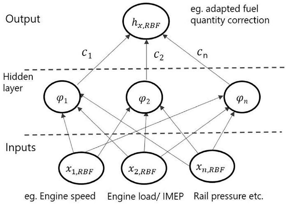
Mathematical description of RBF and its correlation to engine control application parameters.
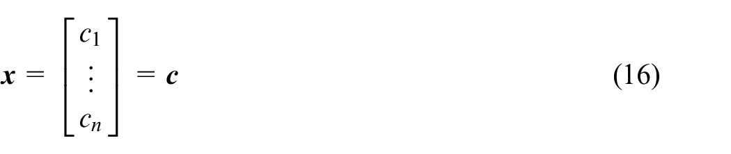
Here,

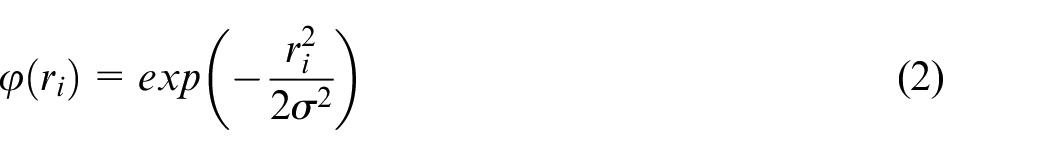
Gaussian form of RBF.
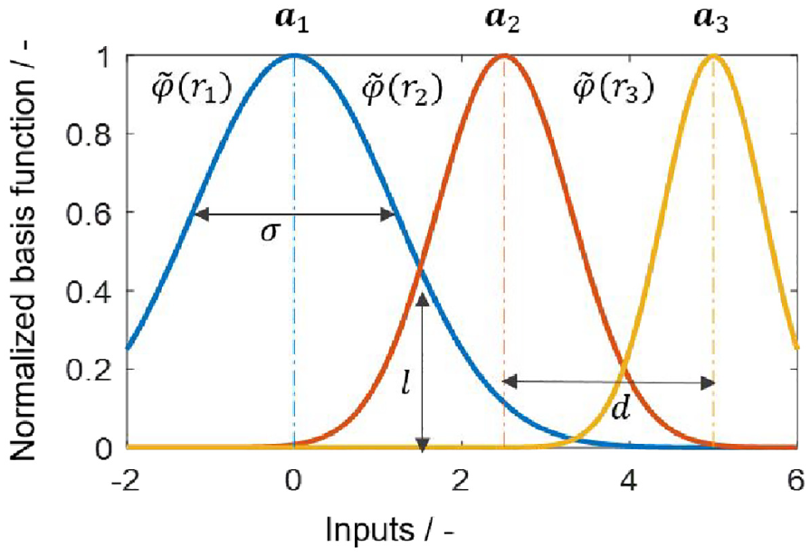
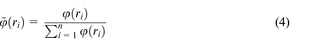
Figure 2 shows the example of three basis functions,
Here,
Here,
Radial basis functions centers
The size of a neural network is directly proportional to the computational effort and therefore is an important step toward real-time capability. The size of a neural network signifies the number of layers and the number of neurons used. Since the number of layers is fixed for an RBF function, that is, three (input, hidden and output layer), the size of RBF neural network is proportional to the number of centers (or neurons) in the hidden layer. To determine the size of RBF, different approaches can be used. One approach is K-means clustering. In this approach, the data points are partitioned into natural groupings or clusters of patterns in such a way that the measure of similarity between any pair of observations assigned to each cluster minimizes a specified cost function as shown in Leonhardt et al. 23 This approach can significantly reduce the number of RBF centers based on data availability and thereby the computational time. However, considering the intended real-time application, this approach is not further considered in this work, since storing the volatile data and online formation of clusters would lead to high memory requirements and computational costs. Thus, a fixed type RBF network is investigated.
In a fixed type RBF, the centers of the RBF network are fixed and do not change during runtime. The centers cover the entire operation region uniformly or can be varied to increase the density of the RBFs and thus the accuracy in certain areas, as shown in Figure 3. With a fixed
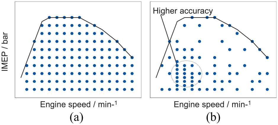
(a) Fixed RBF centers and (b) fixed RBF with varying distribution.
Kalman filter for training of radial basis functions
The Kalman filter based approaches have already been proven to be computationally efficient and suitable for engine control applications in Guardiola, Höckerdal and Guardiola et al.8,14,16 Therefore, Kalman filter was considered here for further investigations in combination with RBFs. As mentioned in the objective of this work, the learned value should not be susceptible to noise and should be accurate. To address this issue, the Kalman filter algorithm is modified to ensure that the learning problem is independent of input data and that noise is avoided. Only the parameters
Kalman filter basics
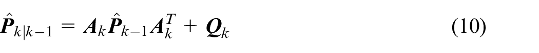
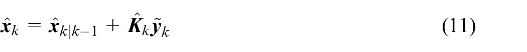
A key property of the Kalman filter is that it is the minimum mean-square (variance) estimator of the state of a linear dynamical system. 36 The solution is recursive; each updated estimate of the state is computed from the previous estimate and the new input data, so only the previous estimate requires storage. In addition to eliminating the need for storing the entire past observed data, the Kalman filter is computationally more efficient than computing the estimate directly from the entire past observed data at each step of the filtering process. 26 The basic working of Kalman filters in neural networks is same as for estimating the state of the system. State estimation using discrete Kalman filter consists of two steps – state update (prediction) and measurement update (correction). The state update equations are used to determine an a priori estimate and the measurement update equations are used to get a posteriori estimate.26,27,36
First, the general equations of the Kaman filter are explained and then a stepwise derivation to the final equations:
State equations,


Here,
With,
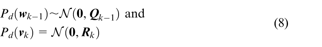
Here, the probability distribution of

Here,
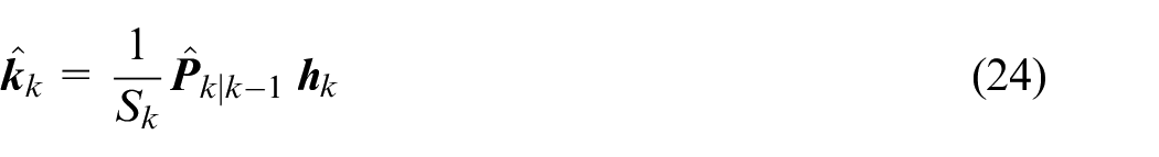
Correction,
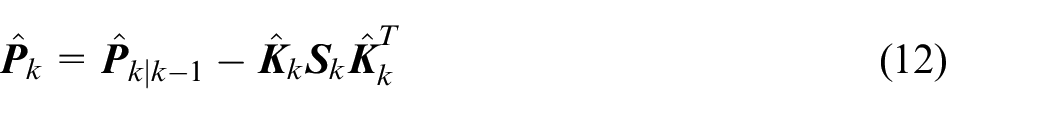
Here,


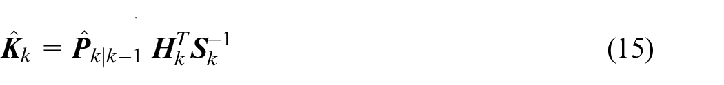
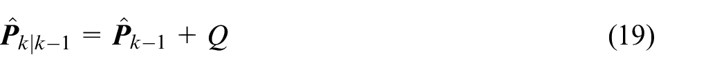
Equation (6) to equation (15) are the standard Kalman filter equations but for weights update in RBF simplification are necessary such as

Therefore, the new prediction and correction equations are:
Prediction,

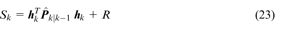
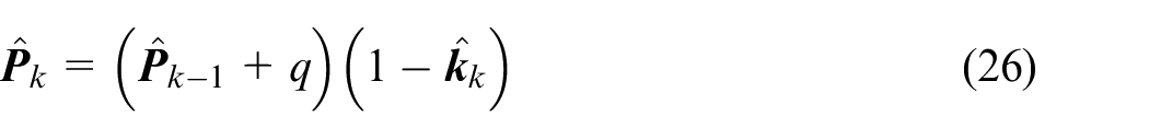
Correction,

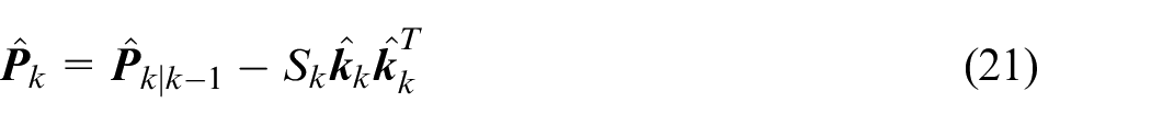
with,

Kalman filter for local constant models
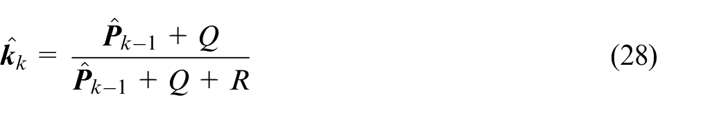
The KF applied to individual local terms of RBF reduces the computational effort and increases stability and robustness. Moreover, to ensure a fast adaptation, it is necessary to separate the learning problem from the input data completely. This approach can be realized with updating the state-equations with

With,

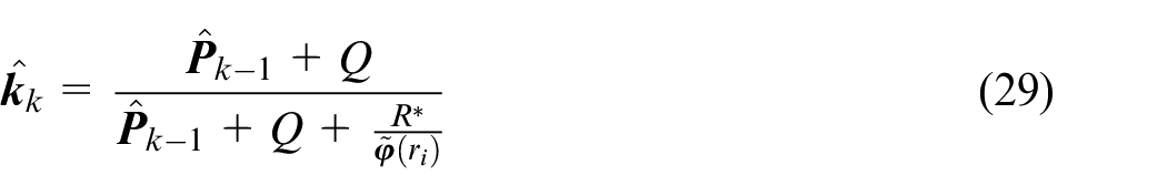
Kalman filter for local constant models with varying measurement noise
An important objective of this work is to realize sufficient training accuracy and robustness such that the trained value is not susceptible to signal noise. Therefore, a modified form of Kalman filter is derived here for robust weight updates by introducing an additional term
Control parameters
The mathematical parameters of RBF and Kalman filter directly affect the training performance. Therefore, the significance of these control parameters and an optimal control value range is explained below.
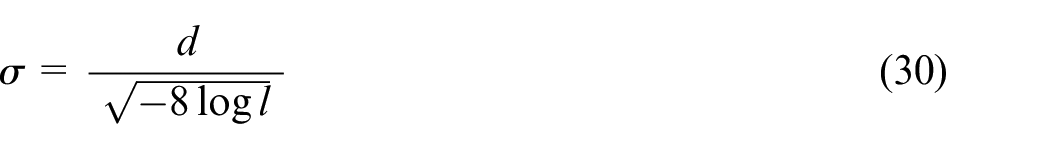
Here, d is the distance between the RBF centers in respective dimension and
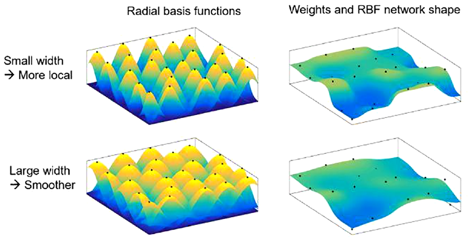
Significance of the σ value to radial basis function (left) and corresponding weight update (right) for two inputs.
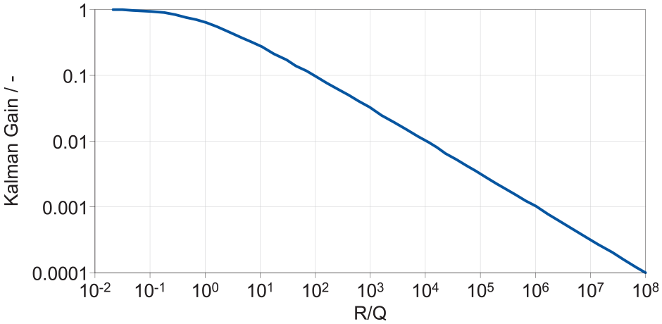
Kalman gain correlation with R/Q.
Control concept implementation
Adaptive feedforward control
As explained in the introduction section, the adaptive control concepts can be implemented in a feedforward path to continuously update the pre-control values. The implementation concept is shown in Figure 6 where the feedback error for a given control concept is learned continuously and can be stored as a function of two or more independent variables.
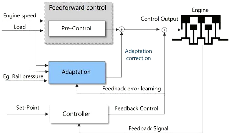
Adaptive control – feedforward error learning.
The adaptive feedforward control is integrated with the closed-loop IMEP control to learn the fuel quantity control correction. The learning function is integrated for two parameter dependencies as shown in equation (31) for simulative investigations and functionality check.

Since a key aspect of the developed learning algorithm is multiple parameter dependency in comparison to look-up tables, an additional factor is added to the implementation of the IMEP control during the validation, namely fuel rail/injection pressure in addition to engine speed and load. The function is described as in equation (32).

Feedback model adaptation
Analogous to adaptive feedforward control, the concept can also be applied to control system with limited sensor response. A generic implementation of the concept to update the semi-physical models is shown in Figure 7.
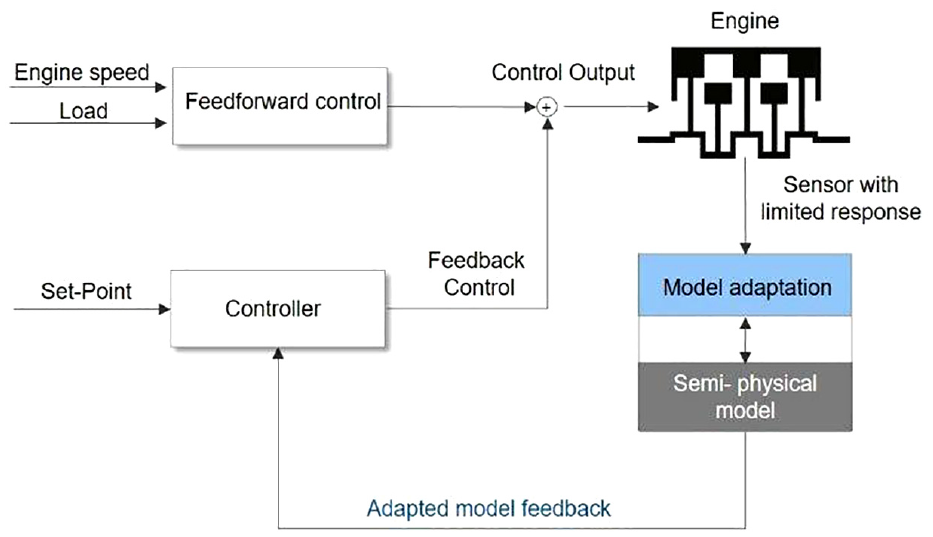
Adaptive control – learning model error with limited sensor response.
The control application identified to demonstrate the potential of this approach is NOx model adaptation where the sensor response is limited in terms of dynamic response. As described in Schaub et al. 7 the inverted NOx model is used calculate the desired O2 concentration set point to realize the EGR control. Therefore, in cylinder O2 concentration is one of the decisive control parameters for EGR rate calculation. To take this into account the identified parameters for model adaptation considered in this study are engine speed, load, and in cylinder O2 concentration, as shown in equation (33).

Training activation
An additional boundary condition that needs to be considered for application of adaptive control functionalities is the activation of the training conditions to ensure that correct values are learned. The training condition is activated only when quasi-stationary conditions are met that means the air and fuel mass flows are stable, and the vehicle is not in overrun mode. The feedback sensor is present and the measured values are plausible. In addition, application-specific conditions such as a quasi-stationary feedback signal and control parameter convergence are necessary for the accuracy of the learned values. Once all these conditions are met and are found to be stable for a certain time period, the training is activated. An overview of possible conditions for training activation is shown in Figure 8.
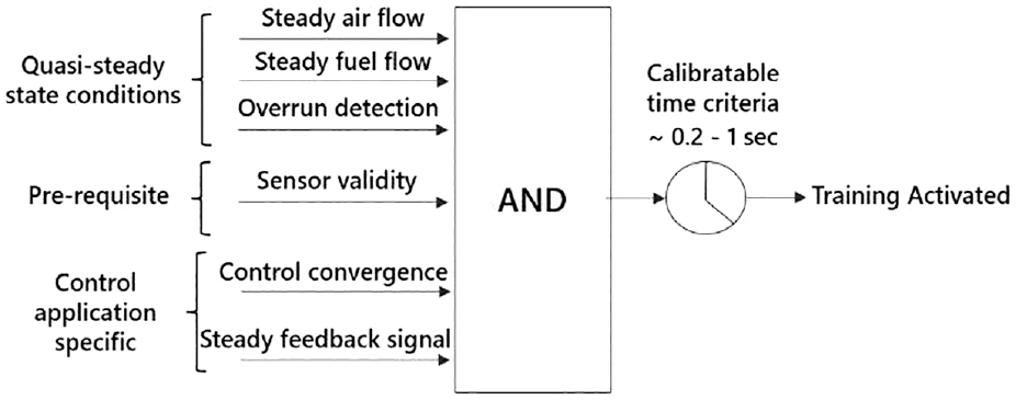
Conditions to activate the model training for adaptive control concepts.
Evaluation and validation
The control functionality with RBF and both KF training algorithms with local constant model (fixed noise) and the proposed approach with varying measurement noise is implemented in form of MATLAB/Simulink codes. Firstly, simulative investigations are performed to compare the performance of the proposed KF algorithm in a simulation environment. In the second step, experimental investigations are performed. A light duty 2.0 L, four-cylinder diesel engine was chosen for the validation. The specifications of the engine are listed in Appendix II. Later on the developed algorithm was validated on a demonstrator vehicle of the same engine family in real-world scenario. The test bench and demonstrator vehicle are built up with RCP (Rapid Control Prototyping). An additional variable introduced on the vehicle during the validation phase is the operation with a carbon-neutral fuel blend that is, OME3-5, 37 to demonstrate the control potential in flex-fuel operation, which is a potential driver for greenhouse gas reductions.
Simulative investigations
The simulative investigations have been carried out with adaptive feedforward closed-loop IMEP control with dependency to two parameters as shown in equation (31). To simulate the scenario of drifted feedforward control, an injector drift is performed on the engine test bench by scaling the complete injector energizing time map with a factor such that the desired load (IMEP) is not reached for the entire engine operation range. The drift is simulated in a way such that ∼2–8 mg less fuel is injected depending on engine operating point. Therefore, the IMEP control compensates for the load deviation by correcting the total amount of fuel injected. This feedback error is used as a training value for the evaluation of the developed concept, as shown in Figure 9 for both steady-state and transient data. The performance evaluation criteria used here are the
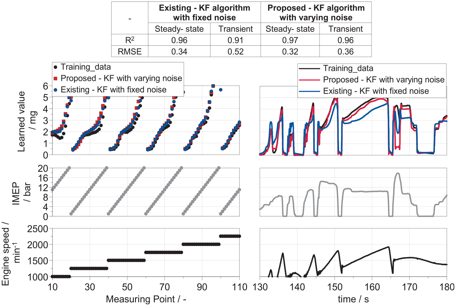
Evaluation of the developed training approach in simulation environment: steady-state analysis (left), transient analysis (right).
In the steady-state case, a similar level of accuracy is observed for both approaches. However, in the transient case, the proposed KF algorithm with varying noise performs ∼30% better in terms of RMSE. This is because the lower the RBF value
Experimental investigations
RCP system built up
The engine test environment is set-up with a RCP system that consists of two elements, the prototyping unit ETAS ES910 and a programmable FPGA (Field Programmable Array) device integrated with a MicroAutoBox-II from dSpace. Figure 10 shows the principal diagram of the development system used. Since the conventional cylinder pressure indication system on test bench is quite slow, a FPGA device is used to provide the combustion characteristics feedback signal with minimal delay. The control concept is executed on the ETAS ES910 and a bypass system on ETK is used to write the output of the code (fuel-injection profile) on the ECU. ETK is a powerful, high speed, universal microcontroller interface that provides access to the ECU’s memory for sophisticated applications in development and calibration of ECU functions. 38
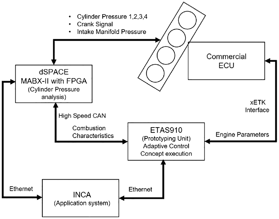
RCP system set up – engine test bench.
The demonstrator vehicle is set up with a stand-alone MABX-II as a prototyping unit integrated with FPGA and operated with stand-alone fuel and air-path control software. Figure 11 shows the schematic diagram of the development system used. A RapidPro device from dSpace is integrated to acquire the sensor signals and/or control the actuators (injectors, valves etc.).
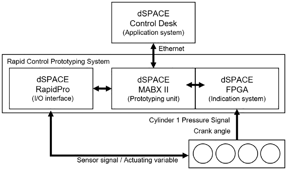
RCP system setup in the demonstrator vehicle.
Functionality check – engine test bench
The functional check of the control concept is performed on the engine test bench at an exemplary engine operating point (1200 min−1 and 6.2 bar IMEP) and its application to IMEP control is evaluated. The learning function is integrated for two parameter dependencies as shown in equation (31).
Analog to simulative investigations, an injector drift scenario is simulated by scaling the complete injector energizing time map with a factor such that a lower fuel quantity (∼2–8 mg depending on the operation point) is injected leading to an IMEP drift in the system as shown in Figure 12. In the second step, the closed-loop IMEP control is turned on so that the total injection quantity is increased as shown in the governor output. The training function is activated and the training value slowly increases to ∼2 mg (drift compensation). The speed of training here is directly controlled by the Kalman Filter gain. Once sufficient convergence is reached, the training is switched off. In the time span from 500 to 600 s a feedback correction of ∼1 mg is learned. This is a result of extrapolation which updates the near-by centers in the RBF network to have a smooth behavior. In the next step, the same load step is performed in open-loop and it can be seen that the learned values can compensate for the drift just in open loop. The trained values are not only accurate, but also lead to a fast convergence (improved transient response) in this case. The initial tests thereby validate the developed adaption concept in controlled steady-state environment where the training and convergence is ensured due to the steady-state scenario. However, a vehicle application would require additional criteria for identification of quasi-steady state conditions so that sufficient training accuracy and convergence can be ensured, as described in Figure 8. Thus, the next step is to perform validation on the vehicle.
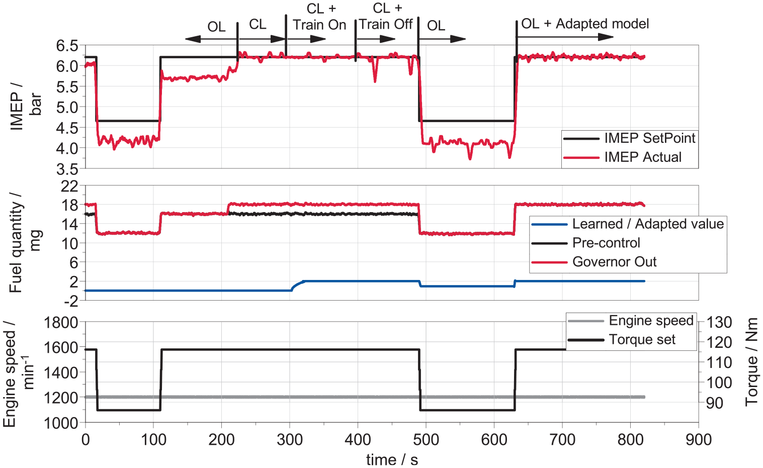
Adaptive IMEP control functionality check.
Concept validation
The concept is further validated in real-world scenario on the demonstrator vehicle to evaluate the potential in terms of accuracy, robustness and performance.
Control accuracy evaluation
The adaptive feedforward IMEP control concept with dependency on three independent parameters as shown in equation (32) is used to demonstrate the potential in terms of accuracy under transient conditions over the entire engine operating range. The investigation is carried out with a carbon neutral fuel that consists of 65% Diesel and 35% OME3-5. The detailed fuel properties in comparison to fossil Diesel fuel are shown in Appendix III. The difference in the lower heating value (∼20% lower comparison to Diesel) of the fuel is particularly challenging for the control concept. The investigations are carried out in open-loop and it can be observed that the IMEP set point is not reached, because the feed-forward control model in this case is calibrated for Diesel fuel. The injected quantity is not sufficient to compensate for the heating value difference, as shown in Figure 13 (left).
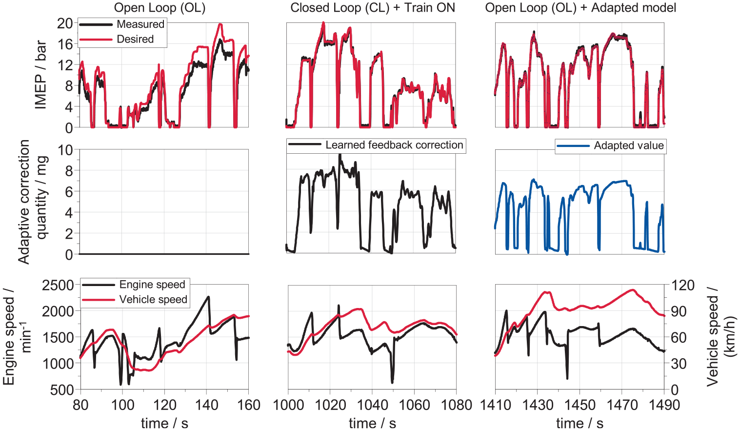
Accuracy of the adaptive control concept – open-loop (left); closed-loop with training ON (center); open-loop with adapted model (right).
In the second step, the closed loop controller is activated, and the weights of the RBF are updated by learning the feedback error. This is shown from the learned feedback correction value trace in Figure 13 (center). The training is performed in real-world operation for ∼400 s by driving the vehicle with engine speeds between 1000 and 2500 min−1 IMEPs ranging from 3 to 20 bar. To demonstrate the training accuracy, the IMEP controller is switched-off and a stretch is further driven in open-loop with the adapted model. As can be seen in Figure 13 (right), the fitted model is so accurate that the IMEP setpoint is reached with feedforward control only. This shows the accuracy of the developed approach even under transient conditions.
Control robustness
The control robustness of the concept is evaluated in WLTC test cycles driven with an OME fuel blend. The feedback error learning and control correction for IMEP control are applied from the start of the first WLTC cycle. At the end of the test cycle, the learned values are stored in the controller memory. To evaluate the reproducibility, a second WLTC cycle is driven. The adaptive IMEP control is activated again at the start of cycle, with the learned values stored in the memory correcting the feedforward control and, at the same time, adjusting the model if a control deviation is observed.
Figure 14 shows the comparison of the adaptive quantity correction with the feedforward path from both cycles for a section of the WLTC. It can be observed that the adaptive quantity corrections are comparable and do not significantly deviate if the boundary conditions are not changed. The minor deviation in the engine speed and load profiles can be accounted to the influence of the driver and the roller dyno resistance. A comparison of the mean adaptive correction quantity at the end of two cycles stored in the controller memory shows a minor difference of ±0.10 mg.
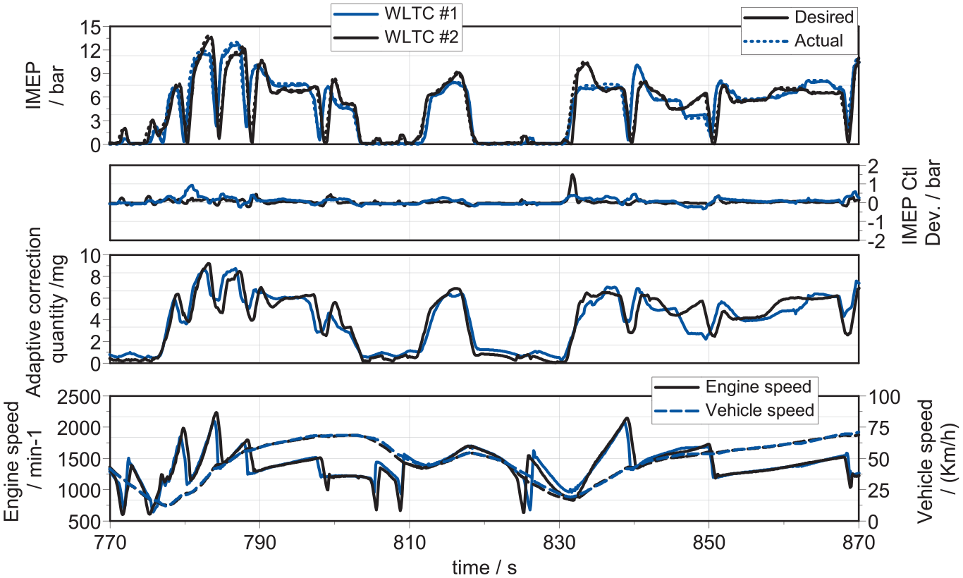
Evaluation of the robustness of the adaptation concept in an extract of the WLTC cycle.
Control performance – model adaptation
An additional application of the developed learning approach is the adaptation of real-time models on the ECU. Therefore, a NOx model adaptation as described in Figure 7 is chosen to demonstrate the control performance in a real-world scenario. The adaptive learning problem is formulated according to equation (33) with dependency on three independent parameters.
Since the NOx model adaptation is based on a slow sensor, for a real-time application, it is necessary to investigate how fast the NOx model can be adapted in case of inaccuracies. The control response is demonstrated after an engine cold start at 22°C in a real-world scenario, as shown in Figure 15. It can be observed that the NOx sensor takes about 60 s to start up, and at about 85 s the stable conditions for the NOx sensor are reached. Since the engine is in idle state, the other activation conditions as described in Figure 8 are also fulfilled, and the model training is turned on. The model converges to the sensor values in ∼15 s as soon as the sensor output is stable. Thus, the model inaccuracies are reduced real-time and the feedback can be used for efficient EGR control.
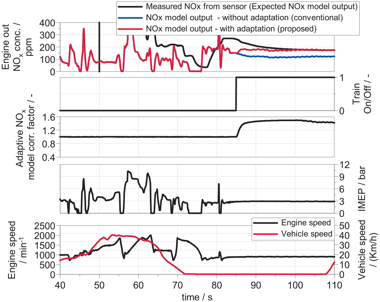
NOx model adaptation – control response after engine cold start.
Summary & outlook
Summary and conclusions
The work presented in this paper aimed to develop a real-time adaptive control concept for engine control applications. The requirements for real-time applications are considered and a fixed RBF network with predefined centers is chosen. Optimized parameters for the RBF network are calculated for sufficient control performance in real-time applications. Thereafter, a modified Kalman filter (KF) is derived to be used in combination with RBF to reduce the susceptibility to signal noise and increase training accuracy with necessary simplifications for real-time capability. The developed KF approach is evaluated and shows ∼30% better training accuracy in comparison to approach without variable noise consideration. The developed control concepts are integrated into engine control software. The real-time capability of the developed control concept is demonstrated on two different RCP systems, namely the ETAS ES910 with bypass and the stand-alone dSpace MABX–II system. The potential of the control approach to continuously adjust the feedforward path is demonstrated using closed-loop IMEP control with multiple parameter dependency, and sufficient control accuracy and robustness of the approach is shown. In addition, the potential of the control concept is demonstrated in cases with limited sensor response and, as an example, NOx model fitting is chosen. Investigations show a fast-training response and the potential of the concept to adapt the semi-physical models online.
The developed control concept is more suitable to this application than methodologies such as deep neural network (DNN)-based nonlinear model predictive controller methods for several reasons. Firstly, it provides transparency to the neural network behavior. The learned values can be visualized by plotting the weights against centers which is not possible with multiple hidden layered neural networks such as DNN’s and transparency in engine calibration is required to adhere to regulations. Secondly, DNN’s require higher computational capabilities and not suitable for real-time applications where computational capability is limited. Additionally, this method can also deal with non-linear problems by transforming it into a linear Gaussian problem and with the assumption that the noise (
Outlook
The control concepts are developed and validated on Rapid Control Prototyping (RCP) systems to demonstrate real-time capability. In a next step, the functions will be implemented in a state-of-the-art commercial control ECU and investigated across different test platforms. Moreover, the influence of NOx model adaptation during the WLTC cycles will be investigated to evaluate the emission benefits. A detailed investigation of the developed adaptive control functions with engine raw emission models for upcoming On-Board Monitoring (OBM) limits or models used in predictive control functionalities could be further explored. In addition, further application of the developed generic adaptive control functions to applications such as fuel cell vehicles or battery electric vehicle and even driver assistance systems would be of interest and can be explored.
Footnotes
Appendix
Declaration of conflicting interests
The author(s) declared no potential conflicts of interest with respect to the research, authorship, and/or publication of this article.
Funding
The author(s) disclosed receipt of the following financial support for the research, authorship, and/or publication of this article: The project on which this report is based was partially funded by the Federal Ministry of Economics Affairs and Energy with the number 19I18006. The authors are responsible for the content of this publication.