
Abstract
Combustion diagnostics of highly diluted air fuel mixtures are of great importance for reducing the carbon footprint of various types of combustion systems. Flame detection techniques, such as ion sensing and optical diagnostics, have been reported for diagnosing combustion status. In this paper, a flame front detection technique based on active plasma probing is introduced and analyzed. Unlike the conventional ion sensing used in internal combustion engines, a separate electrode gap is used to detect the flame front arrival. Further, the voltage potential across the electrodes of the spark plug probe is modulated actively to be slightly below the breakdown threshold prior to flame arrival. At the arrival of the flame front, the ions in the flame tend to decrease the breakdown voltage threshold and trigger a breakdown event. An optically accessible constant volume combustion vessel is employed to investigate the efficacy of such active plasma probing for the detection of the flame front under quiescent and flow conditions. Three types of fuels are used in the tests, including methane, propane, and DME, with an air fuel ratio sweep (from stoichiometric to extremely lean) for each fuel. Efforts are made to characterize the probing criteria of minimum, yet adequate voltage to succeed in the detection of the arrival and departure of the flame front most sensitively and reliably, for all three types of fuels under various mixture strengths. For comparison, conventional ion current measurements are conducted under identical background conditions to benchmark the efficacy of flame detection. Results show that the active plasma probing can promptly detect the arrival and departure of the flame front, robustly regardless of the fuel type and excess air ratios. The precise control of the detecting voltage is key for reliable flame detection with high sensitivity.
Introduction
The clean combustion of lean and diluted air fuel mixture can further enhance the energy efficiency of various types of combustion systems, which is critical to future environmental sustainability. The key objective is to optimize combustor operation, monitor the process, and alleviate instabilities and their severe consequences. 1
Lean or diluted mixtures have much lower chemical reactivity compared with traditional stoichiometric mixtures, leading to a much lower laminar flame speed.2,3 Higher turbulence intensity is therefore needed to speed up the flame propagation process for the applications that demand high flame propagation speed, such as internal combustion engines. However, enhanced flow speed also induces ignition failure and combustion instability.4,5
Under such background conditions, flame detection techniques are important tools for both, research and application purposes.6,7 Flame detection can be realized via multiple techniques, such as optical diagnostics, ion sensors, and so on. Optical diagnostics either uses schlieren imaging to record the flame front movement, 8 or uses a laser to perform either PIV or species analysis to trace the movement of the flame front.9,10 Such kinds of methods have high temporal and spatial resolutions, thus making them ideal for mechanism study on flame structure and propagation. 7
Ion sensors, on the other hand, utilize ions generated during the combustion process to detect the flame front arrival. 1 Figure 1 shows a schematic of the laminar flame propagation of a spherical flame kernel. Ion-rich area exits at the flame front because of the chemical ionization. 11 This process occurs during elementary reactions, when the energy of the reactants, together with the reaction energy, are large enough to ionize one of the products of a chemical reaction involving neutral species.12,13
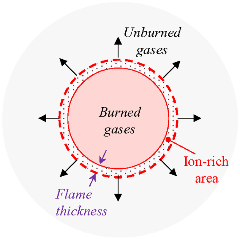
Laminar flame propagation of a flame kernel.
Thermal ionization can also be used to reflect the overall combustion process, especially in internal combustion engines, when the in-cylinder temperature and pressure are sufficiently high. This enables the transient diagnoses of mass fraction burn,14,15 engine knocking,16,17 misfire,11,12 or even pre-ignition. 13
A typical bias voltage of approximately 100 V 18 is sufficient under the stoichiometric and slightly lean conditions for generating strong ion current signals for combustion diagnostic purposes. Under highly diluted combustion strategies, ion density during combustion processes is reduced because of the lean mixture and much lower combustion temperature. The combination of these adverse conditions induces challenges for traditional ion current sensors.10,15
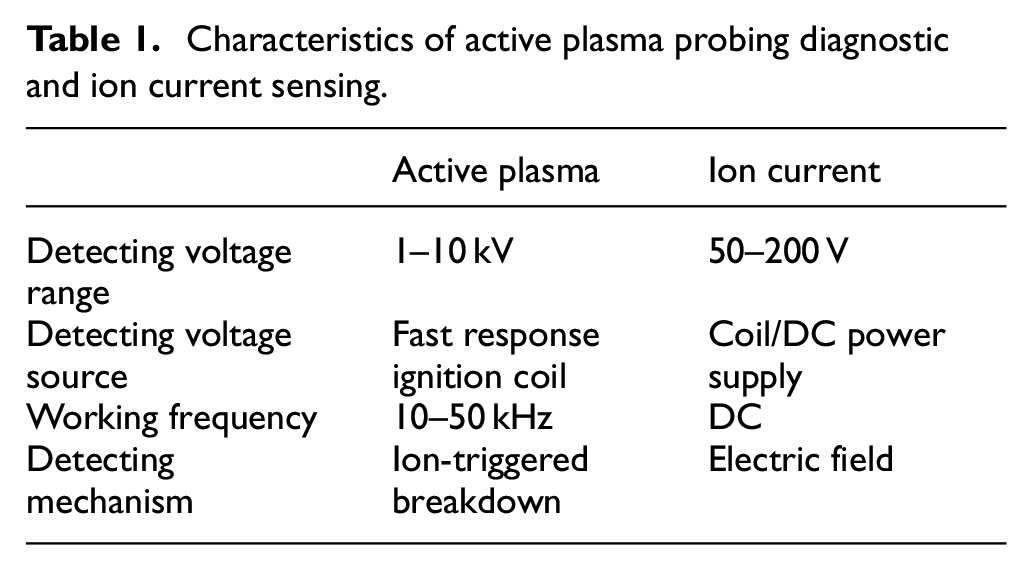
In this paper, a flame front detection technique based on active plasma probing is investigated for the first time. Unlike ion sensing used in internal combustion engines, a separate electrode gap is used to detect the flame front arrival. The voltage potential across the electrodes of the spark plug probe is modulated actively to be slightly below the breakdown threshold prior to flame arrival. The ion-rich region at the flame front, shown in Figure 1, can decrease the breakdown voltage threshold, and a breakdown event can be triggered by the flame front. The specifications of the active plasma probing and conventional ion current diagnostics are summarized in Table 1.
Characteristics of active plasma probing diagnostic and ion current sensing.
Experimental setup
The experiments were performed on an optically accessible constant volume combustion chamber platform. Active plasma detection circuit and ion current detection circuit were developed and used to detect flame front arrival under various excess air ratios using three types of fuels: methane, propane, and dimethyl ether (DME). The measurement results were verified with simultaneous high-speed shadowgraph images.
Constant volume combustion chamber platform
The schematic diagram of a constant volume combustion chamber platform is shown in Figure 2. An Environics 4040 gas divider is used to prepare air fuel mixture with flexible control over the excess air ratio. A spark plug is mounted on the side of the combustion chamber and is connected to a traditional ignition coil to generate the initial flame kernel. Another spark plug is mounted on the top of the combustion chamber and is connected to the combustion diagnostic system, active plasma probing, or ion current.
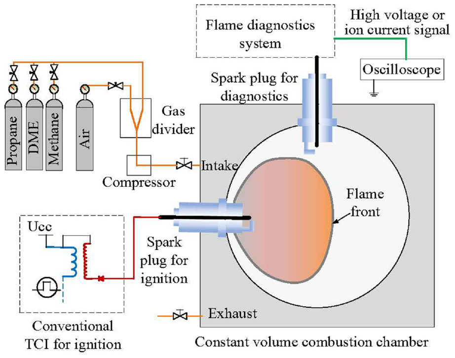
Constant volume combustion chamber platform with flame diagnostic systems.
To generate a flow field mimicking the tumble flow in spark ignition engines, three gas channels are arranged at one side of the chamber, along the tangential direction, as shown in Figure 3. With this design, a global swirl flow field is generated inside the chamber. In this swirl flow field, the peripheral region of the chamber has the highest swirl ratio, while the turbulence intensity gradually decays along the radial direction of the flow field.
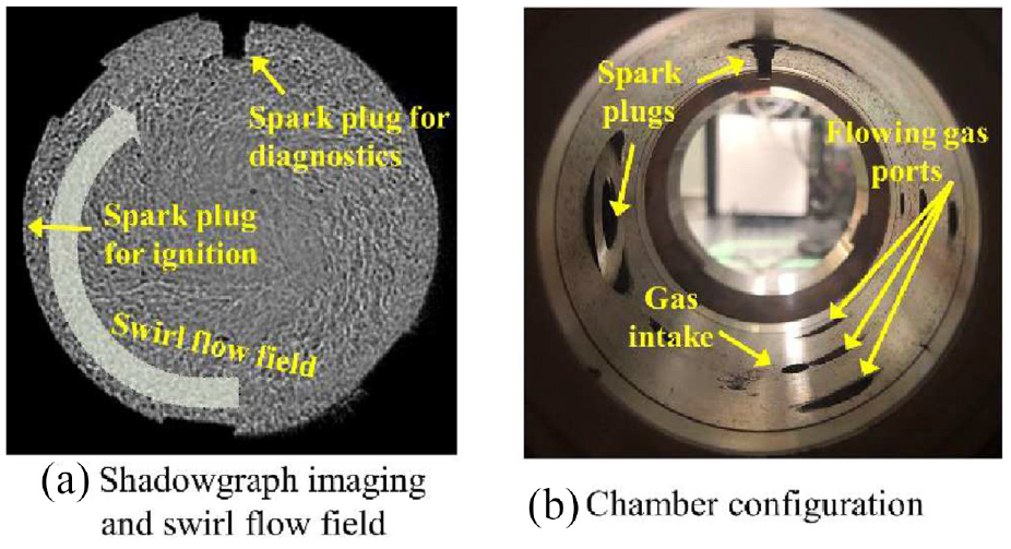
Constant volume combustion chamber platform with flame diagnostic systems.
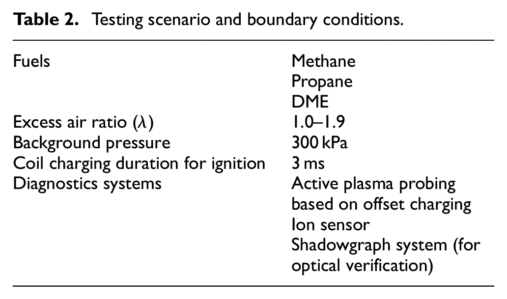
The testing conditions have been tabulated in Table 2. Three types of fuels with different chemical reactivity were used, in order to verify the flame detection mechanism. For each fuel, a lambda sweep was performed from the stoichiometric air fuel ratio until the lean burn limit was reached. Background pressure was maintained at 300 kPa. for all test conditions. The active plasma probing flame detection method was first tested, followed by the ion current detection method under the same background conditions. The measurements have been repeated three times for each testing condition.
Testing scenario and boundary conditions.
A Z-type shadowgraph imaging system was used to observe the actual arrival timing of the flame front at the spark gap. The high-speed imaging results were compared with the flame detection signals for verification.
Active plasma probing diagnostic system based on offset charging
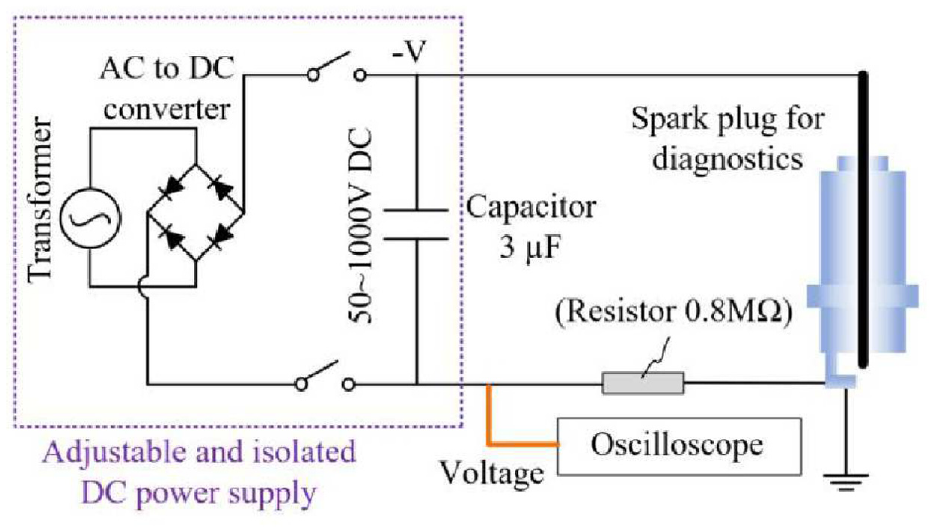
The schematic of the active plasma probing diagnostic system is shown in Figure 4. The basic function of the system is to establish a high voltage potential across the probe spark gap (hereafter termed as “detecting voltage”). The detecting voltage level was maintained marginally lower than the breakdown voltage. Detecting voltage and current were measured by Tektronix P6015A high voltage probe and Pearson 411 current probe, respectively. The measured waveforms were collected using a 4824A Picoscope. At the arrival of the flame front, the high ion density in the flame could trigger the breakdown event and activate the plasma channel. The sudden drop in the detecting voltage potential could thus be used as an indicator to mark the arrival at the flame front.
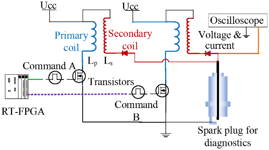
Active plasma probing diagnostic system based on offset charging.
The key to a successful flame front detection is the precise control of the detecting voltage. A pair of ignition coils were connected in parallel to the probe with high inline voltage diodes to provide electrical insulation between the two coils. The two coils were controlled independently, with synchronized control commands sent from an RT-FPGA system.
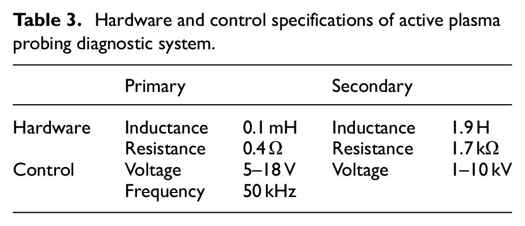
Under real applications, boundary conditions, including background temperature and pressure, air fuel ratio, and fuel types are likely to change, which demands a prompt and precise tuning of the voltage level. A high working frequency for the ignition coils is therefore preferred to dynamically control the detecting voltage level within preferable ranges. Customized ignition coils are designed with primary and secondary inductances 10 times smaller than the present automotive ignition coils, as shown in Table 3 with detailed specifications of hardware and control. Such design of coil parameter allows the ignition coils to react with charging duration as short as 10 μs using 12 V primary voltage, compared with millisecond-level reaction time for traditional coils.
Hardware and control specifications of active plasma probing diagnostic system.
The control command train and detecting voltage waveforms of a flame detection event under a non-reactive background condition are illustrated in Figure 5. The charging and discharge durations of both coils were set to 20 μs, with a time offset of 20 μs from each other. The charging durations of the first charging event for both coils were 30 μs in order to build up the high detecting voltage faster. The detecting voltage potential across the spark gap was built up to 4 kV within 100 μs and was then maintained at this level throughout the detection duration (10 ms).
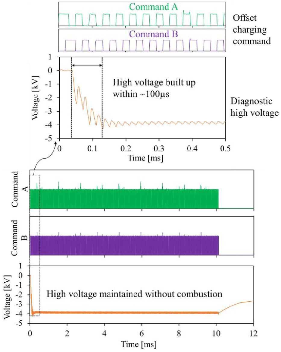
Command signals and detecting voltage of active plasma probing diagnostic system.
Ion current diagnostic system
The electric circuit of the ion current detection is presented in Figure 6. The bias voltage was provided by an auxiliary high voltage supply, which can supply floating voltage up to 2000 V. In this experiment, the bias voltage was set to 50 V under stoichiometric and moderately lean conditions, but was boosted up to 1000 V under extremely lean conditions when the ion current intensity was low.
Ion current diagnostic system.
Results and discussion
Flame front detection using active plasma probing under quiescent conditions
The voltage and current waveforms of the detection system with and without flame front arrival are compared in Figure 7. In the demonstrated scenario, methane–air mixture, with an excess air ratio of 1.4, was used. Similar detection waveforms can be observed using all three types of fuels and different excess air ratios.
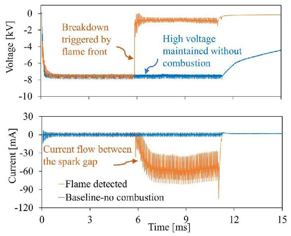
Voltage and current waveforms of active plasma probing diagnostic system.
The blue curves show the reference detecting voltage and current waveforms without flame front arrival. The initial voltage potential of 7500 V is applied and is maintained at the same level throughout the detection period, as shown in the blue voltage waveform. No obvious change in the detecting current waveform is noticed without flame arrival.
For cases with flame propagation, a breakdown event is observed at the arrival of the flame front (waveform in orange color), represented by a sharp increase in detecting voltage from −7500 to −500 V within 10 μs. After the establishment of the plasma channel, a typical discharge process takes place with ∼60 mA discharge current and −500 V discharge voltage.
A direct comparison between ion-current signal and active plasma probing under identical background conditions is shown in Figure 8. It is observed that both methods can detect the arrival of the flame front. For ion current signals, it takes around 800 μs for the signal to rise to peak value, as opposed to ∼10 μs for the active plasma probing method.
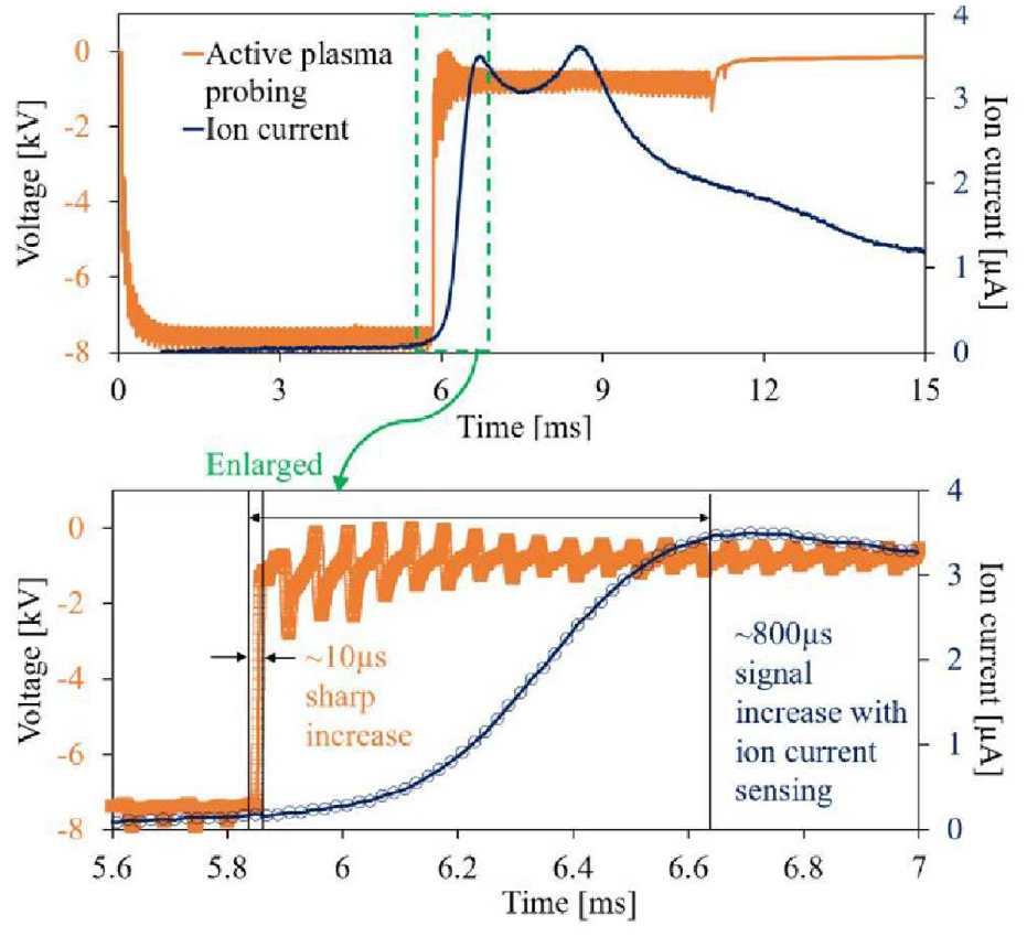
Prompt response of active plasma probing diagnostics. (Fuel: methane, λ = 1.4).
The quick response time can be beneficial under high-speed applications when precise flame front arrival time is important.
Detecting voltage thresholds of active plasma probing diagnostics
The key parameter for a successful flame front detection using active plasma probing is the detecting voltage built up at the high voltage electrode. The voltage should be lower than the breakdown voltage to avoid spark event before flame front arrival but at the same time should also be as high as possible to be sufficient to be triggered by the ions in the flame. The voltage profiles at the arrival of a flame front under various detecting voltages are presented in Figure 9.
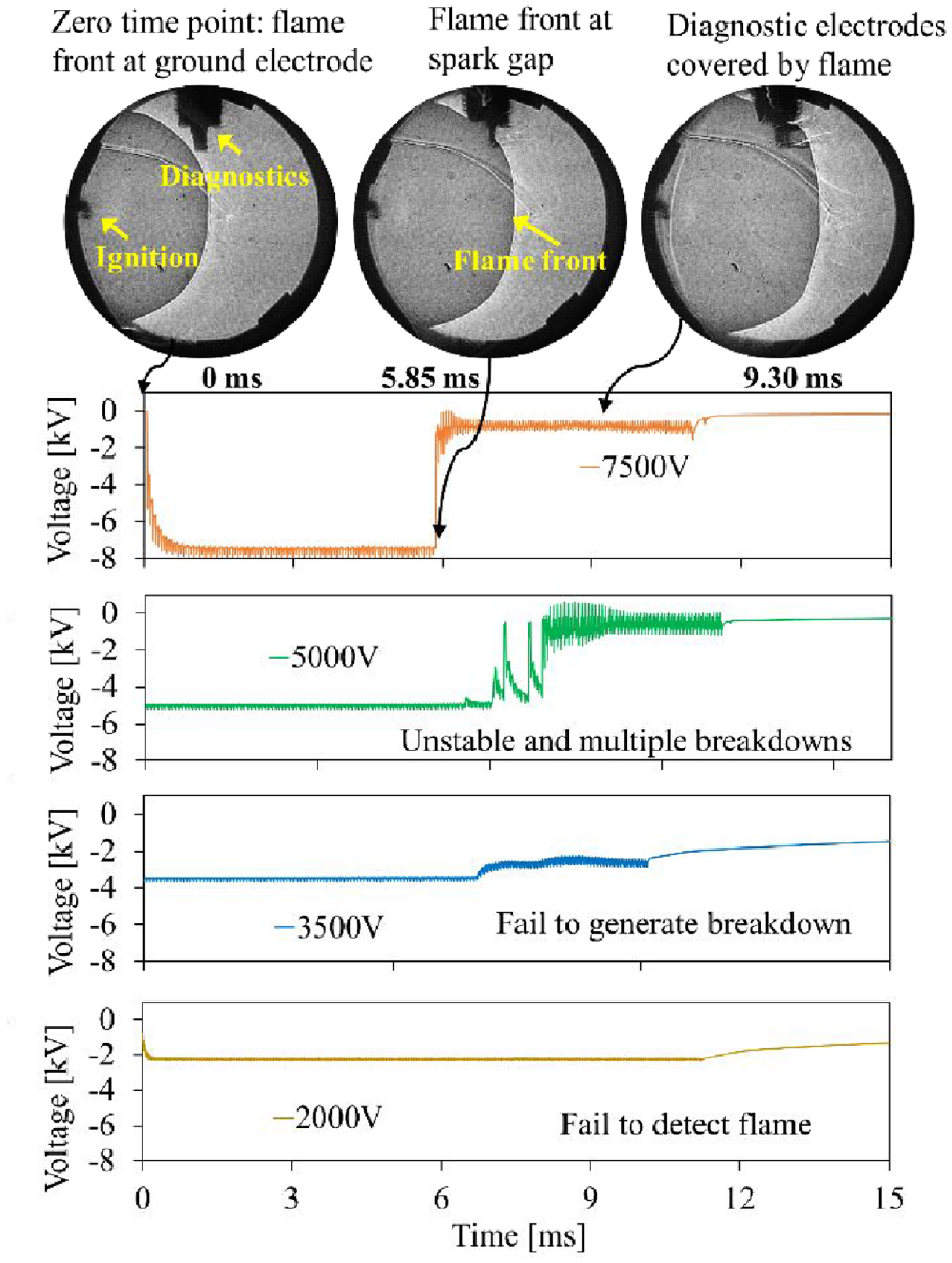
Active plasma probing diagnostic using different detecting voltage. (Fuel: methane, λ = 1.4).
The background condition is the same as in the previous section. A sharp and clear flame front detection is realized with 7500 V detecting voltage. When detecting voltage is reduced to 5000 V, the breakdown event becomes less deterministic with multiple minor breakdown events observed. When the detecting voltage is further decreased to 3500 V, the ions density becomes insufficient to trigger a breakdown, but a slight increase of magnitude and fluctuation in the detecting voltage waveform still indicate the arrival of the flame front. Further reducing the detecting voltage to 2000 V, the active plasma probing method can no longer provide any information about the arrival of the flame front.
For a traditional spark event, the plasma channel is established by ionization of the gas media between a spark gap via high gap voltage. The intense voltage gradients within the spark gap can cause nearby gas to partially ionize and begin conducting. When secondary voltage is lower than the breakdown threshold, the gas molecules remain dielectric and stable. In the case of detection, as the flame front is passing through the probing gap, the electrons and ions in the flame front may collide with gas molecules in the spark gap, thereby enhancing the ionization process and finally making the channel conductive even with lower voltage potential across the electrode gap.
Another possible reason to explain the drop in detecting voltage is the local temperature rise at the arrival of the flame front. The temperature rise can enhance the ionization of the gas molecules, therefore reducing the electric field strength needed to achieve the ionization.
The impacts of excess air ratio on the detecting voltage are further investigated for all three types of fuels, as shown in Figure 10.
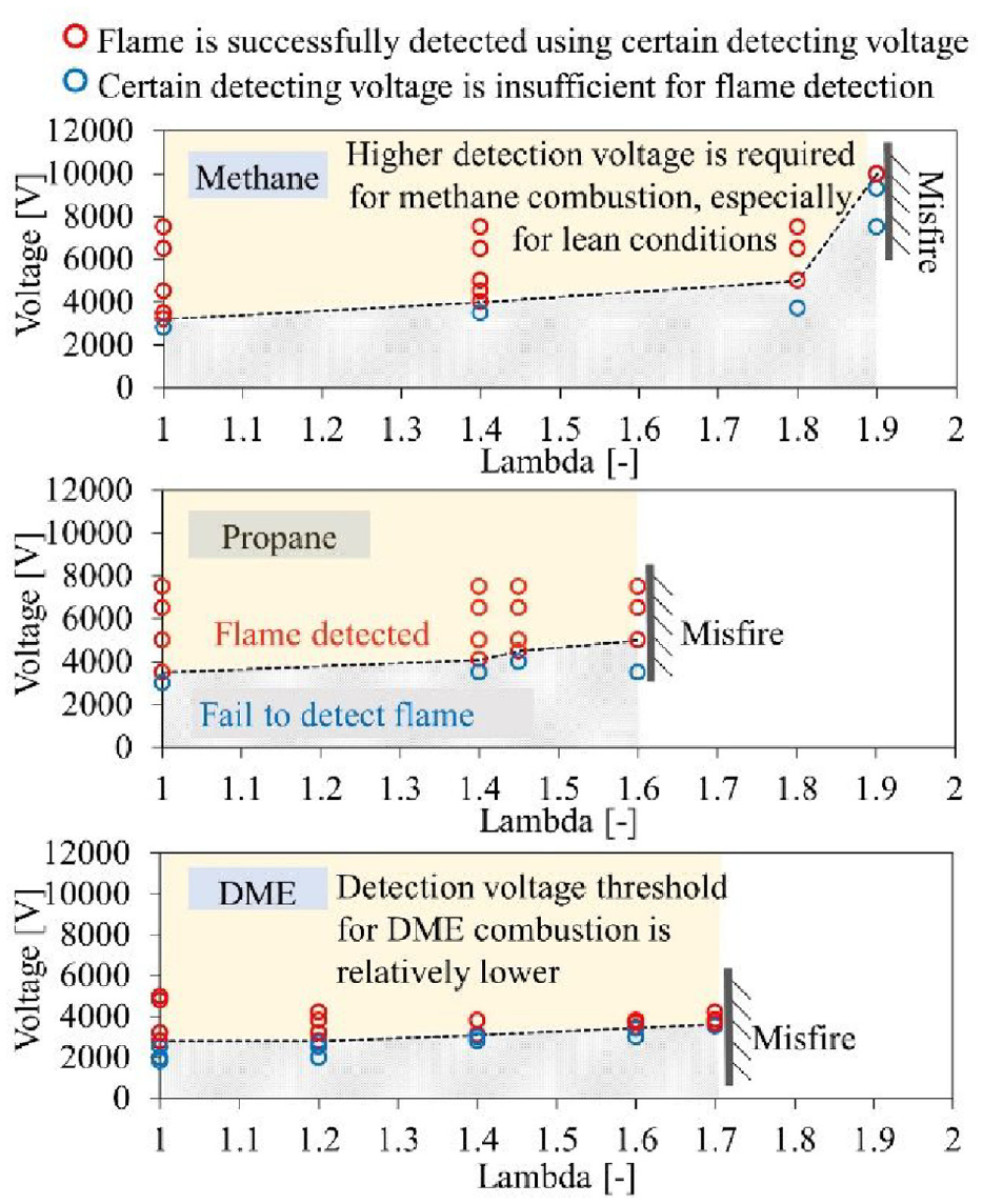
Detecting voltage comparison for stoichiometric and lean combustion using methane, propane, and DME.
For each excess air ratio, a detecting voltage sweep has been performed to find the voltage threshold to succeed a flame detection. The red circles indicate the cases where the flame front is successfully detected (breakdown in achieved), while the blue circles indicate the detecting voltage is insufficient to detect flame front arrival.
It is observed that the detecting voltage threshold increases with the increase of excess air ratio. The reduced ion density and flame temperature weaken the capability of the flame front to trigger the breakdown event, necessitating higher detecting voltage threshold. Such characteristics can also be used to detect the local air-fuel ratio in the vicinity of the spark gap.
When comparing the detection threshold among three types of fuels, it is obvious that methane and propane mixture shares a similar flame detecting voltage threshold under a similar excess ratio, but the detecting voltage threshold for DME fuel is slightly lower. The difference might be attributed to the higher flame temperature of DME, compared with that of methane and propane, 19 or because of the higher ion concentrations of DME flame. 20
Comparison study: Ion current diagnostics
The performance of ion current sensing under various excess air ratios is illustrated in Figure 11. Under the same bias voltage of 50 V, ion current intensity decreases significantly with the increase in excess air fuel ratio of the gas mixture. When the excess air ratio increases from 1.0 to 1.9, the peak ion current intensity drops from 10 to 0.1 μA at the arrival of the flame front.
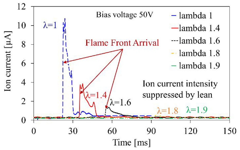
Ion current signal at flame arrival using methane–air mixture under various excess air ratios (λ). (Bias voltage: 50 V).
The results of elevating the bias voltage of the ion current detection circuit under an excess air ratio of 1.9 are shown in Figure 12. When increasing bias voltage from 50 to 1000 V, the peak ion current intensity increases from 0.1 to 0.6 μA. The decrease in ion density in the flame front primarily impacts the detected ion current density.
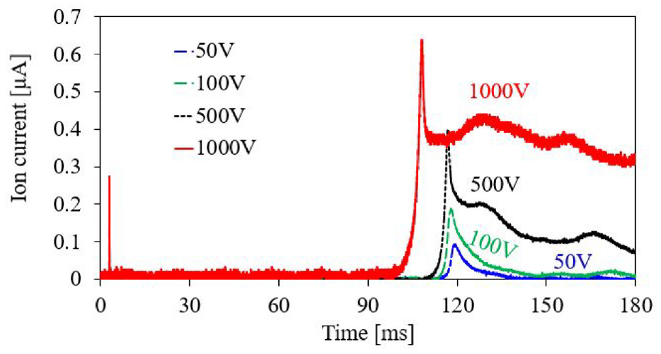
Ion current flame diagnostics using lean methane–air mixture λ = 1.9 with elevated bias voltages.
Compared with the ion current, active plasma probing shows a more consistent detection of the flame front arrival, provided the detecting voltage is sufficient. As shown in Figure 13, when the detecting voltage is 7500 V, robust flame front detection is not affected by the increase in excess air ratio until it reaches 1.8. This detecting voltage becomes insufficient when the excess air ratio is further extended to 1.9, requiring a further increment of the detecting voltage to 10 kV, when the flame front arrival can be detected again.
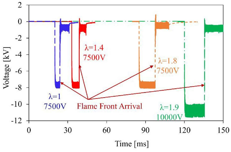
Active plasma probing diagnostics using methane–air mixture under various excess air ratios.
It is noticed that the voltage detection threshold for the active plasma probing method is much higher than that of the bias voltage of the ion current sensing circuits, because of the difference in detection mechanism. However, 10 kV is within the dielectric capabilities of the ignition coils and spark plugs, which are normally rated at 35–45 kV levels.
Flame front detection using active plasma probing under flow conditions
The constant volume combustion chamber used in this research is also capable of generating overall swirl flow with controlled turbulence intensity. Figure 14 demonstrates the capability of detecting both flame arrival and departure under turbulent flow conditions.
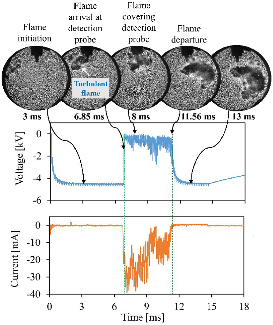
Flame arrival and departure detection using active plasma probing under flow conditions. (Fuel: DME, λ = 1).
A spark plug mounted horizontally on the combustion chamber is used to generate the flame kernel. The spark plug installed on the top is utilized for flame detection using active plasma. The initial voltage potential is set as 4500 V as shown in the blue voltage waveform. Similar to the flame detection mechanism under quiescent conditions, when the flame front arrives at 7 ms, a breakdown event is observed. The detecting voltage on the active plasma probe increases sharply from −4500 to −300 V. The relatively low voltage maintains for approximately 4.5 ms until the flame departure from the detecting probe. Simultaneous shadowgraph imaging provides the validation of the flame detecting performance using active plasma probing.
Potential application on flame thickness estimation
During the detection voltage sweep test, it is observed that a narrow detection voltage window exits, within which the plasma channel can be triggered by the arrival of the flame front, but is unable to be self-sustained after the departure of the flame front. Similar phenomena are observed irrespective of tested fuels and excess air ratios, and cases using DME/air mixture under excess air ratio of 1.6 are presented in Figure 15 for demonstration.
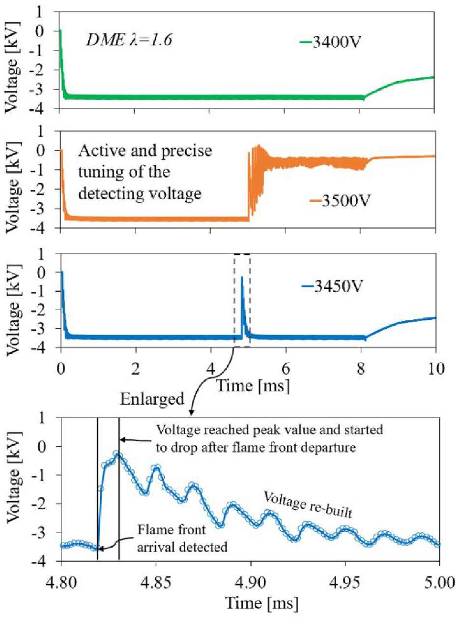
Potential application of flame arrival and departure diagnostics using voltage spikes generated by active plasma probing system. (Fuel: DME, λ = 1.6).
As shown in Figure 15, the detection voltage of 3400 V is insufficient for flame front arrival detection, while the detection voltage of 3500 V can sustain the plasma channel after the flame front departure. When the detection voltage is tuned to 3450 V, just a spike is noticed as the flame front passes the spark gap. As discussed in previous sections, the spike indicates a breakdown event triggered by the ions of the flame front. However, as the flame front departs from the spark gap, the voltage potential provided by the ignition coil alone cannot sustain the plasma channel, and the discharge process is interrupted. Following the spike, the voltage again starts to be built up by the two ignition coils, as shown in the enlarged figure. These characteristics have the potential to assess the flame status for both laminar and turbulent flames.
Conclusions
In this paper, a flame detection technique based on active plasma probing is introduced and analyzed; the results have been further benchmarked with the measurements of ion current sensing and schlieren visualization. Three types of fuels are used in the test: methane, propane, and DME with air fuel ratio sweep for each fuel. The major conclusions of the study are summarized as follows:
With properly modulated flame detecting voltage, the arrival of the flame front can trigger a breakdown event across the spark gap, which can be used to provide robust detection of flame front arrival with a temporal resolution within 10 μs, regardless of the fuel types and excess air ratios.
The threshold of detecting voltage increases with an increase in excess air ratio, which is likely attributed to the lower ion density and flame temperature of the fuel lean mixtures.
The voltage thresholds for methane and propane are approximating each other under similar background conditions, whereas DME has a lower detecting voltage threshold.
The proposed active plasma probing method has the capability of detecting both flame arrival and departure under turbulent flow conditions.
By fine tuning the minimum, yet adequate voltage of plasma probing, a narrow detection voltage window can be reached, where the plasma channel is able to detect the flame front arrival but is unable to self-sustain after the departure of the flame front. Such characteristics have indispensable potential to flame diagnosis or even to measure the thickness of laminar flames.
Future work
The major advantage of the active plasma probing method is the high sensitivity to flame front arrival under extremely lean air fuel mixtures, owing to the high detecting voltage. Prompt and precise control over detecting voltage needs to be enhanced in order to further increase the temporal resolution of the measurement result. Additionally, the performance of this flame detection method needs to be verified under turbulent conditions using leaner mixtures.
Footnotes
Declaration of conflicting interests
The author(s) declared no potential conflicts of interest with respect to the research, authorship, and/or publication of this article.
Funding
The author(s) received no financial support for the research, authorship, and/or publication of this article.