
Abstract
To date, 59 countries, representing 54% of global greenhouse gas emissions have made pledges for net-zero emissions targets within this century. This will require cleaner and more efficient sources of energy which is driving research into small-scale engines and auxiliary power units for hybrid vehicles and stationary power generation. A suitable candidate for such applications is the micro gas turbine due to its high-power density, reliability and low emissions. Further development of such engines is required though due to their increasing parasitic energy losses relative to net power output as size decreases. Additive manufacturing offers the design freedom to not only increase efficiencies but to also reduce emissions when applied to the various components of micro gas turbines. This article reports the effects of several additive manufacturing (AM) enabled design features for micro gas turbine combustion chambers via experimental testing of full-scale parts. The main objective of the additively manufactured features is the reduction of exhaust emissions by improving the air-fuel mixture distribution and consequently ignition and combustion. Using additive manufacturing a novel conical radial swirl-stabilized tubular combustor with internal vane fuel injection was created as a baseline for the laboratory testing. Several other features, including augmented backside liner cooling surfaces, in-vane lattice structures for fuel mixing and upstream liner fuel injection rings were also generated to further the investigations into additively manufactured features and their effects on fuel mixing. Using multiple combinations of all these features, 10 geometries were generated and tested at a variety of operating conditions. Three inlet temperatures were tested (500°C, 600°C and 700°C) with varying fuel flow rates to investigate their operating limits at a constant inlet pressure of 4 bar absolute. Test results for the full range of equivalence ratios and operating conditions showed that the upstream liner fuel injection designs generated NOx, CO and THC emissions on par with the baseline but showed a reduction in the maximum and minimum operating ranges. This design, however, demonstrated the distinct advantage of being able to ignite at full air mass flow; this is not possible with the baseline designs and is also an added benefit to its main use which is the reduction of liner temperature. Overall, the test results underscore that designing combustion chambers for additive manufacturing can provide a myriad of benefits not only for micro gas turbines but also for other applications requiring high efficiency combustion chambers.
Introduction
Mitigating climate change via reduction of greenhouse gas emissions is now part of 59 countries future plans for the end of this century. 1 For all countries this first requires the decarbonization of all energy sources and so traditional combustion-based power units require innovative solutions to drastically reduce their emissions and increase their efficiency. As important as conventional piston engines are to combustion-based power units, there are limitations on how much improvement can be achieved with them. A potential replacement for these is the micro gas turbine, which if developed correctly could rival piston engines in efficiency and generate significantly lower emissions. To achieve these developments though, the ability to create designs which are not constricted by traditional manufacturing methods is required. Additive manufacturing allows for this freedom while also providing faster prototyping and flexible manufacturing capabilities.
This article showcases the benefits of additive manufacturing (AM) in combustion chambers for micro gas turbines. Specifically, it demonstrates how AM features can reduce pressure loss, raise combustion efficiency and reduce emissions. These metrics are evaluated using full-scale laboratory testing.
Micro turbine applications
Currently most micro gas turbines (MGTs) can be found in stationary power and heat generation applications such as providing heat and power to small business and housing and being used as remote power generators. This is due to their capability of running on multiple fuels and the relatively low emissions they produce in comparison to tradition internal combustion generators. Examples of these MGTs include the Ansaldo T100, the Capstone C30, the Bladon MGT and the 3 kW MTT EnerTwin.2–9
In the aeronautical industry, MGTs are being developed as replacements to the commonly used two-stroke piston engine for drones. This is due to the increased service intervals possible due to fewer moving parts and the absence of lubricants in these engines. They are also quieter in terms of noise and vibrations and can be designed to be light too, all of which are beneficial for the drones these engines are applied to. Notable examples of such MGTs include the Monarch 5 engine developed by UAN Turbines for use in small electric hybrid aerial vehicles and for powering turboprop airplanes. 10 Another example is a sub-20 kW engine for small drones developed by the US Navy, the Black Ghost engine.11,12
In the automotive industry the use of MGTs is not common for commercial vehicles but examples of them can be found in specialty vehicles such as the P40 hipercar developed by the Arial Motor Company which is an electric and MGT hybrid vehicle. The MGT was developed by Delta Motorsport and some initial research conducted on its combustion chamber and the use of additive manufacturing for improving the vaporization injector can be found in Adamou et al. 13 Another specialty application is heavy armoured vehicles, such as the US made M1 Abrams which features a Honeywell AGT1500 gas turbine engine, 14 and the Russian made T80 which is powered by a SG-1000 gas turbine. 15 A more promising application for MGTs in the automotive industry is their use in medium-duty vehicles, such as delivery vans, buses and disposal trucks. Examples of these type of powertrains can be found in WRIGHTSPEED, 16 which describes the various MGT and electric hybrid powertrains developed by Wrightspeed.
Although all these projects mentioned above show that MGTs are viable for several applications, mass adoption of this technology has not yet been achieved. This is mainly due to the low power generating efficiencies MGTs achieve in comparison to traditional internal combustion engines. This issue becomes clear when considering the efficiencies of some of the aforementioned examples, such as the Ansaldo T100 which has a power efficiency of approximately 30%, 2 the Capstone C30 with 26% efficiency 5 and the 3 kW MTT Ener Twin with 16%, 7 in comparison some standard IC engines such as the 88 kW Audi 2.5L TDI has an efficiency of 42.6%, 17 and the Toyota Prius 57 kW gasoline engine has an efficiency of 36.4%. 18
The poor power efficiency of MGTs can be attributed to their small size. Larger gas turbines, in the megawatt range, are more efficient because the magnitude of energy losses that occur within them (e.g. due to friction, heat dissipation and leakage) is smaller compared to the power generated. However, such losses become proportionally more significant as the size and power level decreases. The power level in the MGT category is not precisely defined but is typically in the kilowatt range; hence the losses, when expressed as a percentage of the overall power, can be orders of magnitude greater. Although methods of alleviating these issues are possible, such as tighter tolerances or consolidation of parts in areas which can reduce leakage, the increase of operating temperatures, or the reduction in pressure losses via smoother flow geometries, at such small scales they are not yet economically viable using traditional manufacturing methods.
Benefits of additive manufacturing
Additive manufacturing offers a route to improving micro gas turbine performance by enabling higher temperature operation and reduced losses due to leaking joints, while also consolidating the number of parts, leading to significant reductions in system weight and overall size. AM can also be used to create internal passageways for air or coolant flows in locations closer to the heat source, leading to more effective cooling and thermal distribution around the system. Cooling can be further enhanced using novel internal heat transfer surfaces, which would not be possible with traditional manufacturing. Organic geometries which can create low pressure pathways can also be integrated in certain systems, further increasing overall efficiency.
To investigate its potential benefits, the present research applies AM design methodology to a MGT combustion chamber since this component influences all the major operating parameters of the MGT.
Additive manufacturing in combustors
Although there is little published information regarding the use of AM in gas turbine combustors, some notable examples include the LEAP fuel injector developed by General Electric, which significantly reduced both the part count and manufacturing time. 19 The Euro-K multi-fuel micro burner developed by EOS, and the Siemens pre-mixer for the SGT-A05 gas turbine, are other excellent examples of how AM is improving combustion in various gas turbine applications.20,21
Additive manufacturing in reciprocating engines
Additive manufacturing is also finding application for various components in reciprocating engines, to again improve efficiency and reduce emissions. Some of the most noteworthy research includes additively manufactured radial turbines for automotive turbochargers with AM-enabled internal cooling features, 22 the work conducted on improving pistons via topology optimization, 23 and combustion bowls for diesel engines. 24
MGT combustor research
There has been considerably more work conducted on MGT combustion chambers not involving AM. This ranges from the use of synthetic and ammonia mixed gaseous fuels in MGTs,3,25–28 to the use of flameless or MILD combustion to reduce emissions4,29–31 and the development of porous burners and other injection research.32–35 All such research further confirms that numerous different industries are recognizing the potential of MGTs to become viable power generating solutions in the coming years.
Layout of this article
Having introduced the work, the subsequent sections are as follows:
Sec. 2: Experimental Methods describes the target operating conditions, the various AM-enabled test combustor designs and their method of manufacture, and the experimental test facility.
Sec. 3: Results reports the experimental measurements (NOx, CO and THC emissions; pressure drop; outlet temperature) for each of the AM-enabled combustors, with comparison against a baseline design. The impact of combustor design at the MGT system level is quantified by calculations based on a recuperated Brayton cycle.
Sec. 4: Conclusions reviews the main combustor performance improvements enabled by AM-enabled design features.
Experimental methods
Target operating conditions
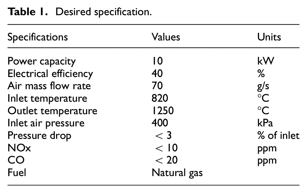
At the outset of this project a set of specifications were generated with the goal of creating a 10 kW MGT system with 40% electrical efficiency. These specifications guided the development of the AM combustion chamber and are shown Table 1.
Desired specification.
Combustor geometries
The effects of AM on fuel mixing are of primary interest for this project since it is desired to operate the combustor at high inlet temperatures, and at ultra-lean fuel/air conditions in order to reduce emissions while improving the overall power efficiency of the MGT system. At the project outset, it was decided along with the industrial partner to employ lean premixed combustion, which requires high quality air/fuel premixing to generate the desired results, hence the following geometries focus on improving air/fuel mixing via AM features.
For the baseline, AM design methodology was applied to a radial swirler with in-vane injection. Using AM, it was possible to create a conical shaped swirler intended to reduce pressure loss by limiting flow separation, which occurs in traditionally manufactured swirlers due to the 90° bend just upstream. The integration of aerofoil-shaped, in-vane injectors and the fuel plenum as a single part is beneficial for two reasons. Firstly, it allows the fuel to be preheated prior to injection. Secondly, it promotes good mixture preparation by exploiting the vortices generated by the aerofoil-shaped injector. This fine detailed structure is only possible due to the ability afforded by additive manufacturing to create small internal structures, and which can be further optimized through the addition of surface textures or fin profiles, for example, depending on fuel type and inlet conditions. The baseline swirler design and its primary dimensions can be seen in Figure 1 and Table 2.
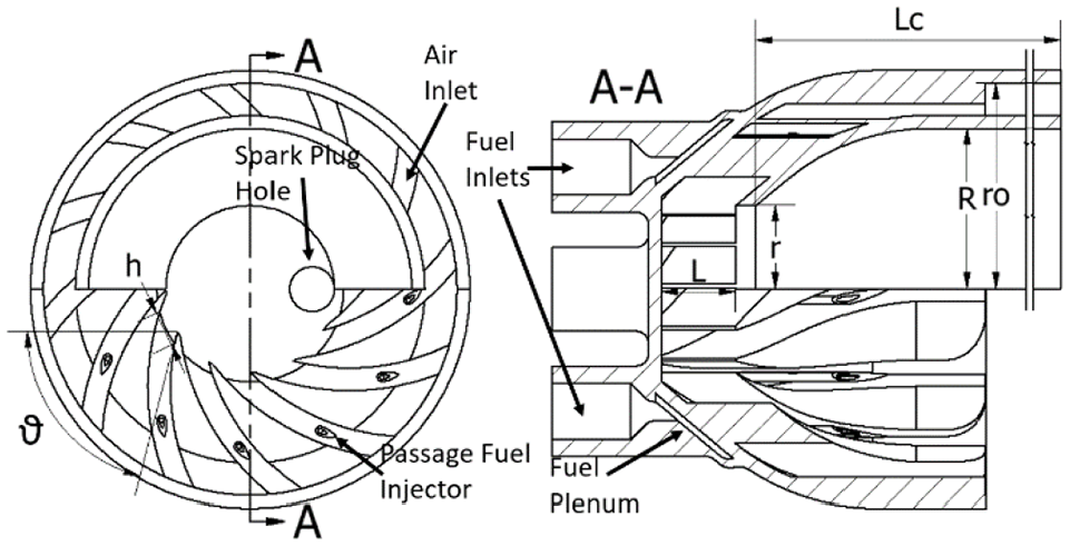
AM radial swirler and combustor configuration.
Radial swirler and combustor dimensions.
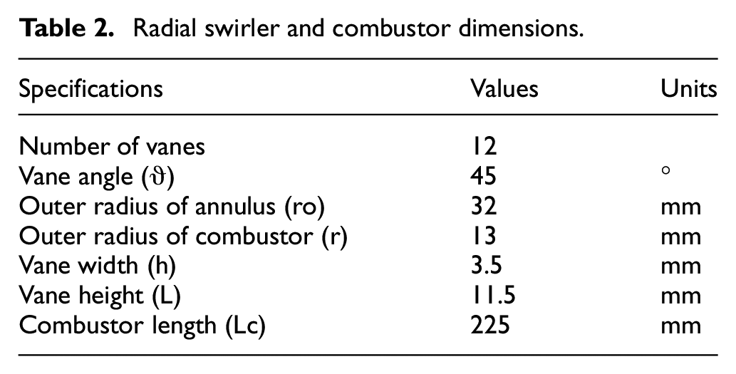
With the baseline established, additional AM features were applied to it with the intention of improving the air/fuel mixing quality. The first feature was created by applying a cube vertex centroid lattice structure with 0.3 mm diameter beams and 1.8 mm sided cube. This structure was inserted into the swirler downstream of the fuel injection point near the exit of the swirler vane with the intention of generating increased turbulence to enhance the air/fuel mixing. Although this would increase pressure losses and induce flow separation it was still desired to investigate the effects of such structures. Two such geometries were created, one with a single row lattice and one with three rows, to investigate the effects of mixing surface volume increase. These designs can be seen in Figure 2, which are cut-outs of a single swirler vane from Figure 1. Noticeable here are the teardrop-shaped fuel injection holes, which were designed in this way to eliminate the possibility of surface defects that sometimes occur in additively manufactured circular holes. For this reason, this shape is used for all fuel injection and dilution holes.
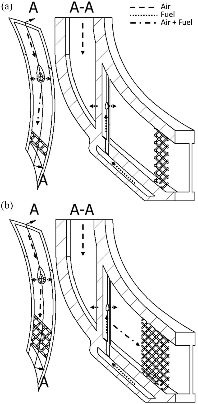
(a) One-row internal lattice and (b) three-row internal lattice.
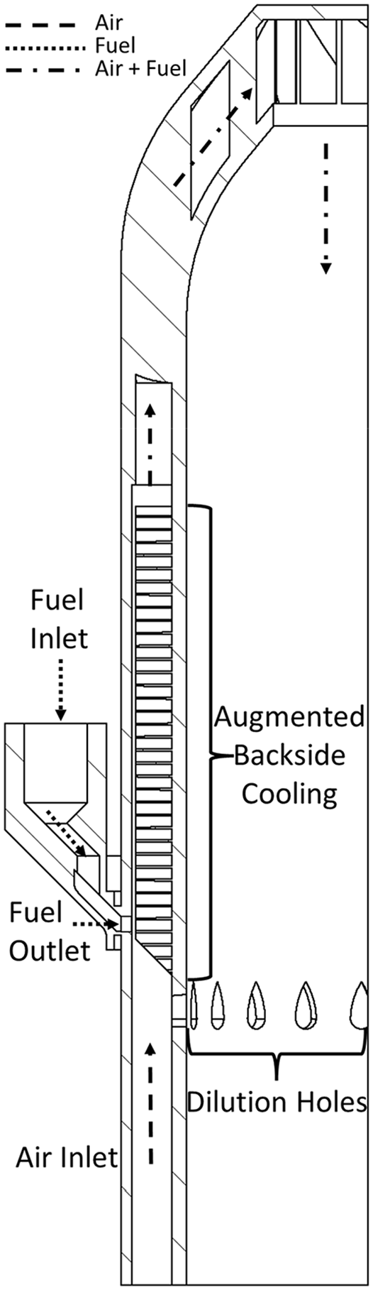
The second feature created to enhance mixing was a fuel ring, comprising of four inlets feeding fuel into a plenum, which then splits into multiple teardrop-shaped outlets, which can be seen in Figure 3. The fuel ring replaces in-vane injection and is placed upstream of the swirler to inject fuel into the annulus of the combustor, where it also interacts with the backside cooling channels to enhance mixing, as seen in Figure 4. The further upstream the fuel ring is placed, the better the mixture quality is likely to be due to increased mixture time, although it cannot be placed upstream of the dilution holes to avoid fuel escaping through them. Since different fuels require different levels of mixing intensity, and may also auto ignite if preheated too much, AM can be used to optimize the mixing process for different fuels and applications by allowing modular placement of injection holes and suitable design of the downstream mixing surfaces.
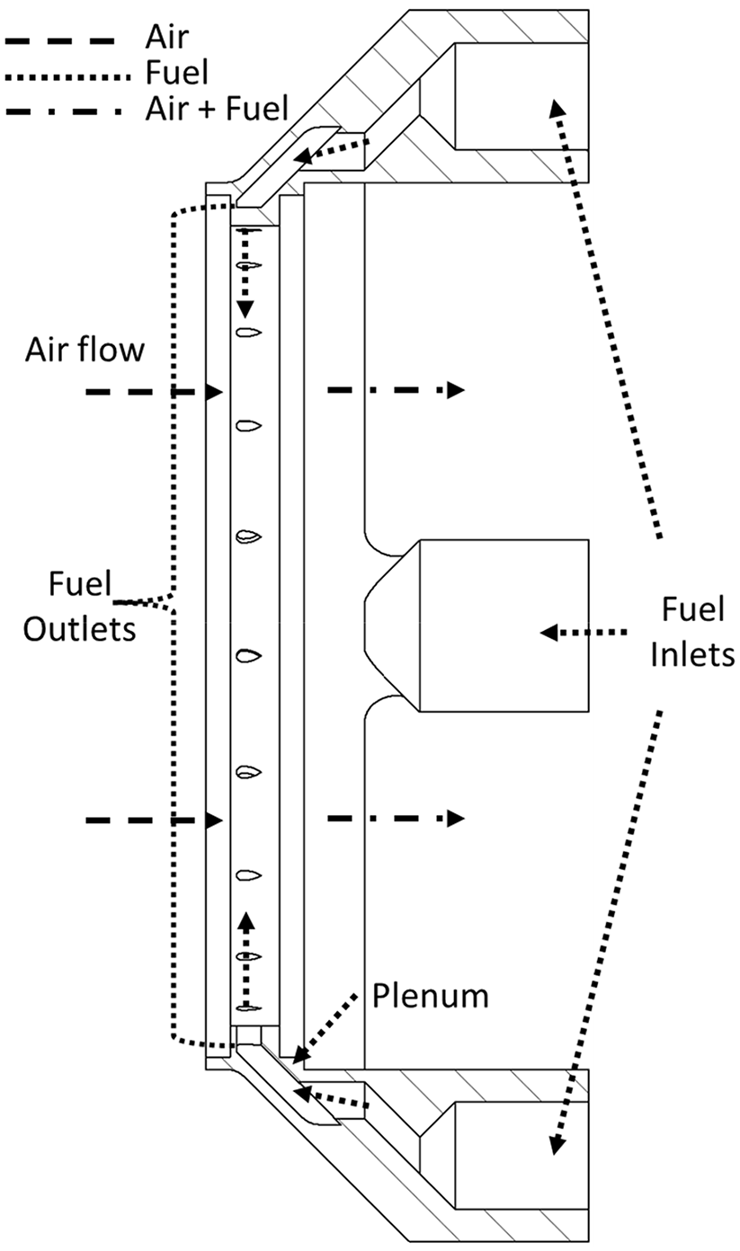
Upstream fuel ring.
Upstream injection geometry.
Although the primary purpose of the cooling surfaces is to reduce the combustor liner temperature, a secondary use, as air/fuel mixing surfaces, is also investigated. Two types of surfaces were evaluated, employing either a curved fin, or an offset strip fin (OSF), both of which can be seen in Figure 5. The main dimensions for the fins are listed in Table 3; further details concerning their design and cooling effectiveness may be found in previously published work. 36
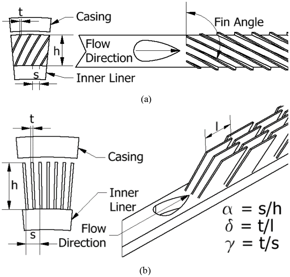
(a) Curved fin geometry and (b) offset strip fin geometry.
Curved fin and offset strip fin dimensions.
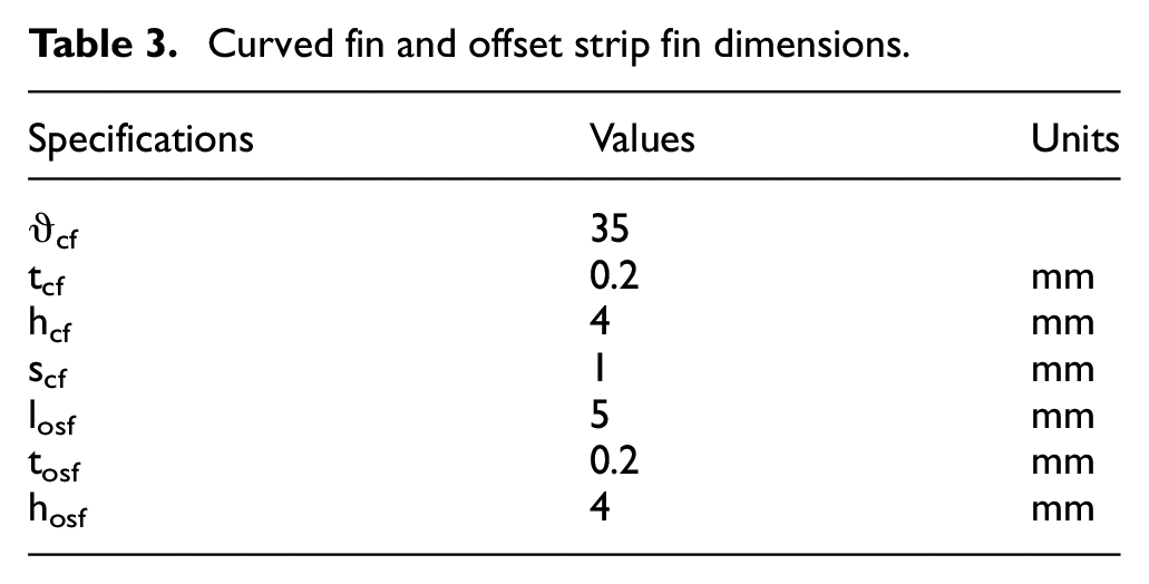
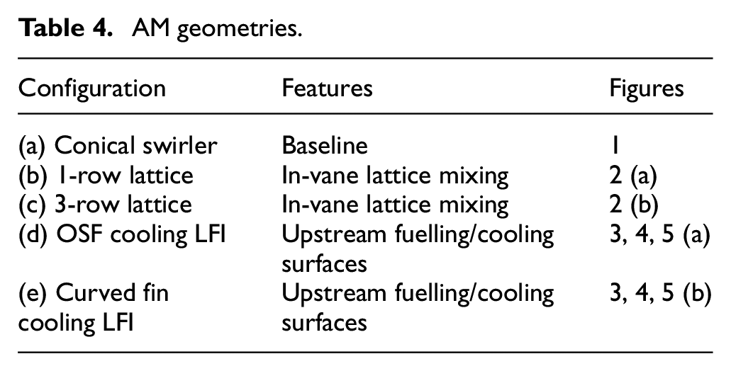
Table 4 summarizes the geometries that were assembled and tested, listing the AM features applied to each geometry and their corresponding figures.
AM geometries.
Combustor build parameters and material specifications
Inconel 625 nickel superalloy was chosen for combustion chamber manufacture due to its excellent high temperature properties. Table 5 lists the key material specifications for Renishaw’s Inconel 625 powder, 37 which is comparable to the one used by the industrial partner in this project. These specifications are for as-built parts using 60 µm layer thickness at 200 W laser power, manufactured using a Renishaw AM250 system, 38 the same as used for this project.
Inconel 625 material specifications for 60 µm layer hight and 200 W laser power.
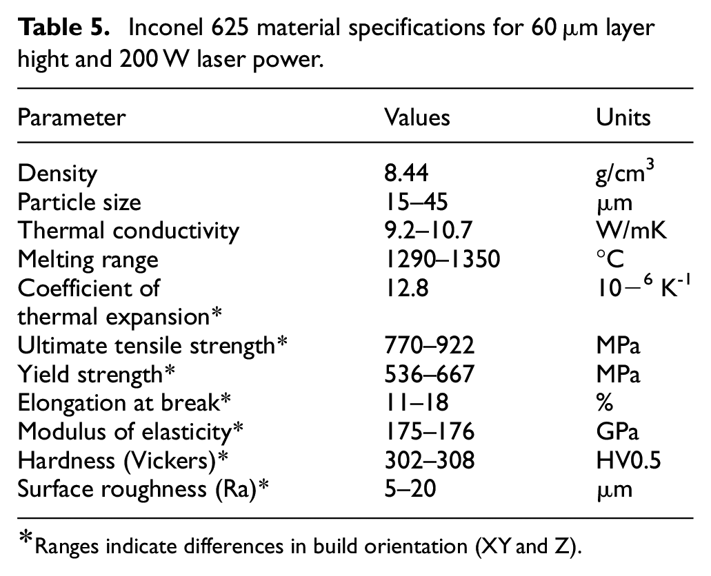
Ranges indicate differences in build orientation (XY and Z).
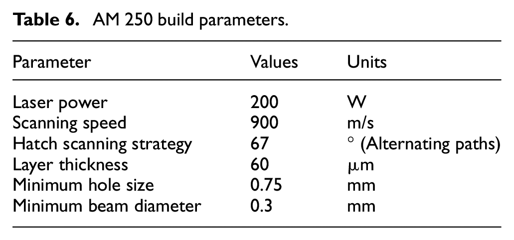
Table 6 lists the settings for the AM250 printer and some of the minimum size build capabilities achieved by the industrial partner at the time of manufacturing.
AM 250 build parameters.
Laboratory test cell
Laboratory testing was conducted using the hot gas stand at the Institute for Advanced Automotive Propulsions Systems (IAAPS), at the University of Bath. As the schematic in Figure 6 shows, the hot gas stand comprises two 35 kW electrical heaters, coupled to two in-cell heat exchangers, which recuperate heat from the combustor exhaust gas. This arrangement can supply heated air at temperatures up to 720°C, depending on the air mass flow demanded, and allows testing of the combustors at full scale, thereby supporting the development of combustor technology which can be directly implemented into commercial systems with minimal alterations. A third AM heat exchanger, provided by the industrial partner HiETA Technologies, was added to further enhance recuperation from the combustor exhaust gases, increasing the maximum temperature achievable to 820°C at combustor inlet.
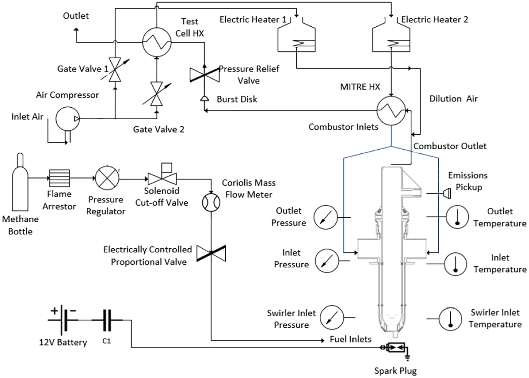
Laboratory test cell schematic.
In Figure 6 it can be seen that the air flow is split between the two heaters. Electric Heater 2 supplies the main air flow into the combustion chamber through the AM heat exchanger (“MITRE HX”). Electric Heater 1 supplies the dilution air flow, which joins the main flow downstream of the combustor outlet. Its purpose is to reduce the combustor exhaust gas temperature to a manageable level for the downstream piping, and to enable fine tuning of the systems pressure, which is also controlled via the electronically controlled butterfly valve placed downstream. V-Cone Flow Meters are used to measure the air mass flow rate. Fuelling of the combustor was achieved using a methane gas bottle with a pressure regulator which reduces the bottles pressure from 200 to 5 bar, a Coriolis mass flow meter to measure the fuel rate; the latter controlled by an electronic proportional valve. Ignition is achieved using an operator-controlled 8 mm spark plug connected to a capacitor powered by a 12V battery. In summary, Table 7 lists the experimentally measured parameters, as well as the corresponding sensor type and uncertainty range.
Experimentally measured parameters.
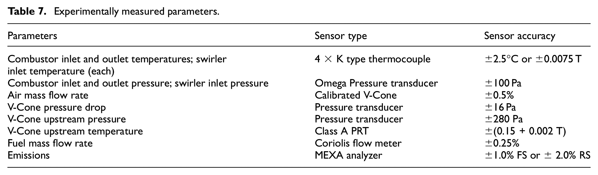
Safety features include: a burst disk to prevent over pressurizing; a flashback arrestor connected to the gas bottle pressure regulator; and several software cut-offs, programmed to shut down the cell in case of temperature and pressure anomalies. Methane and CO2 gas detectors were also placed in the cell in case of leaks.
Figure 7 shows a photograph of a combustor (baseline swirler design) during the start-up sequence; internal and external quartz tubing permits viewing of the flame structure and colour during operation; here, the blue flame suggests low soot combustion. Locations of the various temperature and pressure sensors, the fuel inlets and the spark plug can also be seen in this figure. An emissions probe is inserted downstream of the combustor outlet pressure sensors and connected via a heated line to a Horiba MEXA-7170DEGR analyser, which measures the concentration of CO, CO2, O2, THC, NO and NOx species, (NOx here refers to the combination of NO and NO2 emissions), in the combustor exhaust gas. Measurement ranges vary depending on the component, with the most relevant ones being THC and NOx, which respectively have a range of 0–500 and 1000–50,000 ppm depending on the emissions output of the measured system, and CO, which has a range of 0–5000 ppm.
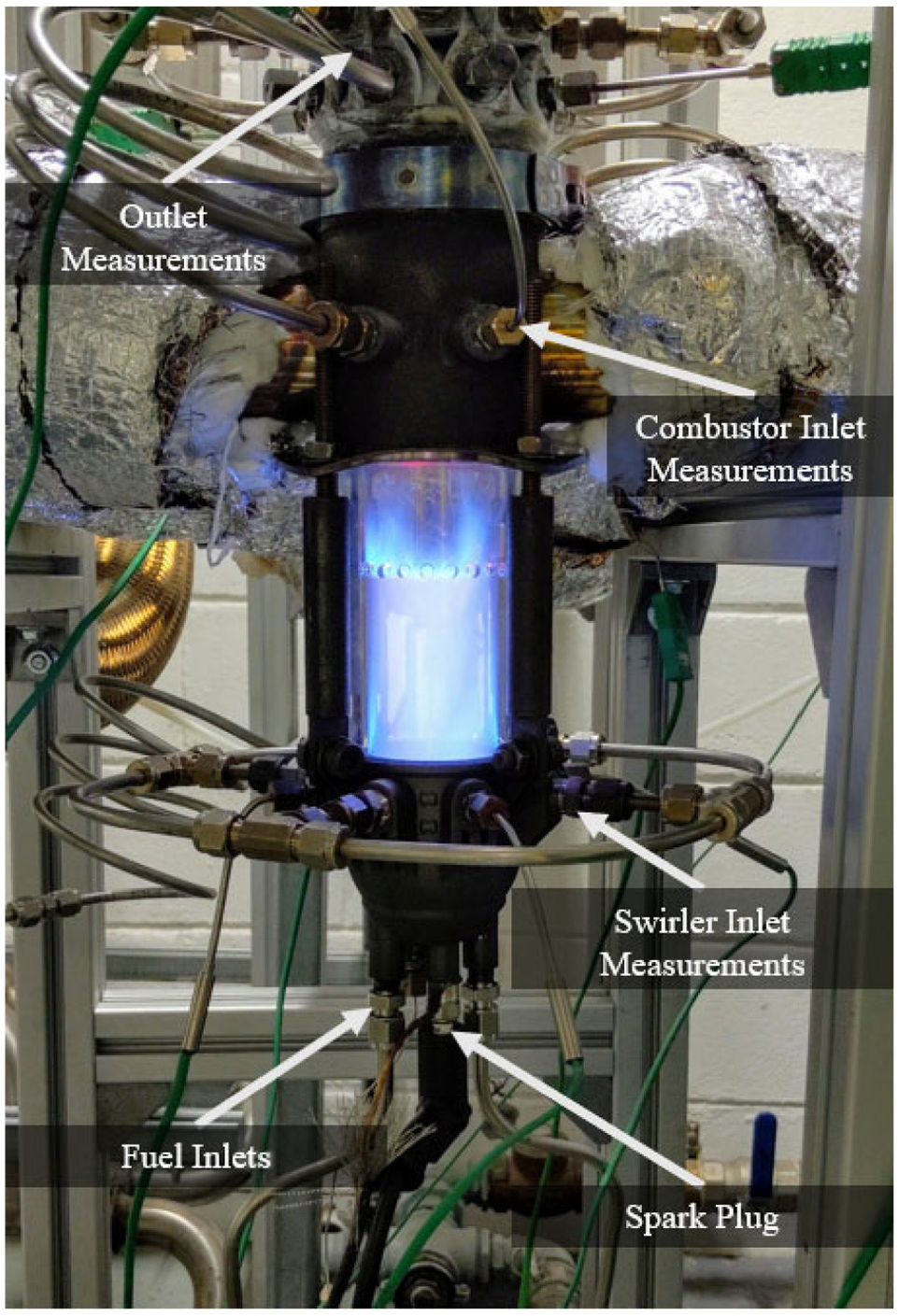
Example of combustor (baseline swirler) during start-up; quartz tubing permits observation of flame structure.
A sectioned CAD model of the combustor is presented in Figure 8, which provides a clearer understanding on how the combustor is assembled and operated. Note the reverse air flow pathway around the periphery of the combustor, which is split between the teardrop-shaped dilution holes and the swirler used to stabilize the flame. The two fuelling schemes used during testing can also be seen, viz., in-vane injection and the upstream fuel ring which is placed just downstream of the dilution holes to avoid fuel entering them.
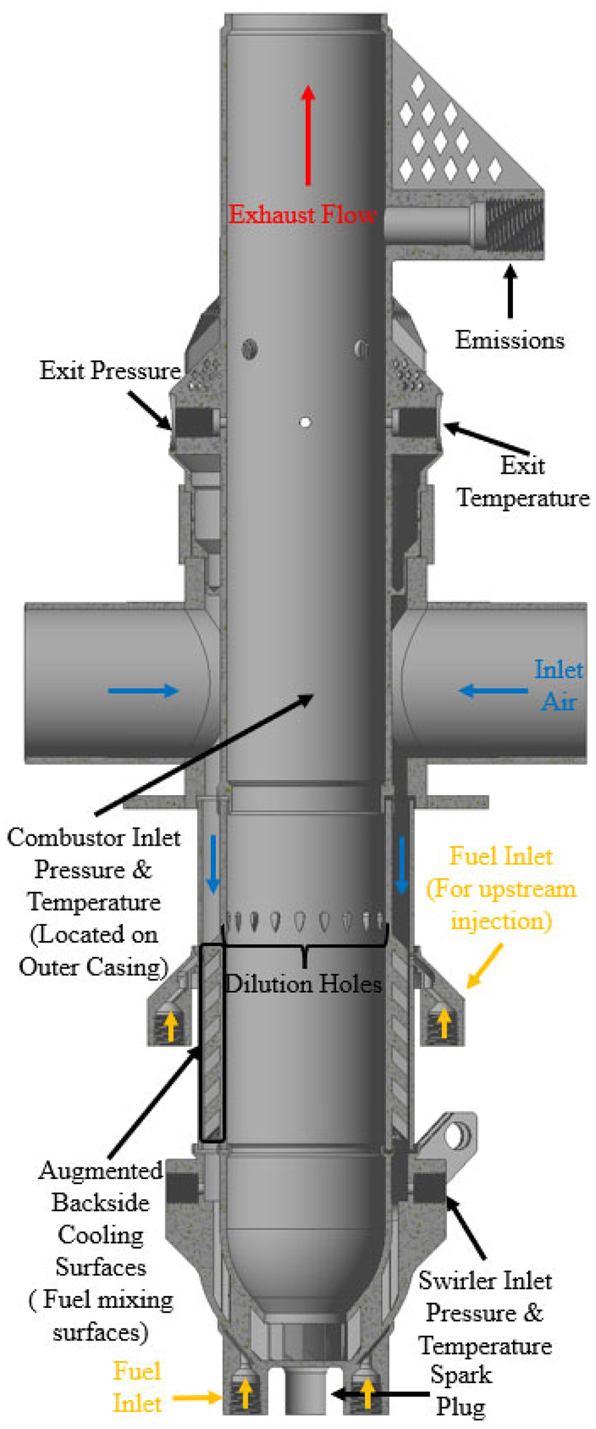
Combustor internal layout.
Modularity of the design is a particularly advantageous attribute of this combustor assembly, since key components must be switched in and out to achieve the different experimental configurations under test. The entire combustor system must be pressure sealed; this is achieved by placing gaskets at either end of the casing and the inner liner. These are mica-based, in order to withstand the high temperatures inside the combustion chamber and compressed using four tie rods between the swirler structure and the flange located on the air inlet. To accommodate differences in thermal expansion, the inner liner is purposely shorter than the casing. Although this creates a small leakage path between the annulus and main chamber at low temperatures, this closes up once operating temperatures are reached.
Figure 9 shows the baseline swirler geometry, following manufacture and heat treatment, identifying the air inlet, the two slots which hold the inner liner and casing, the tie rod mounts, and the spark plug hole, which is purposely offset from centre to avoid exposure to the flame in the combustion primary zone.
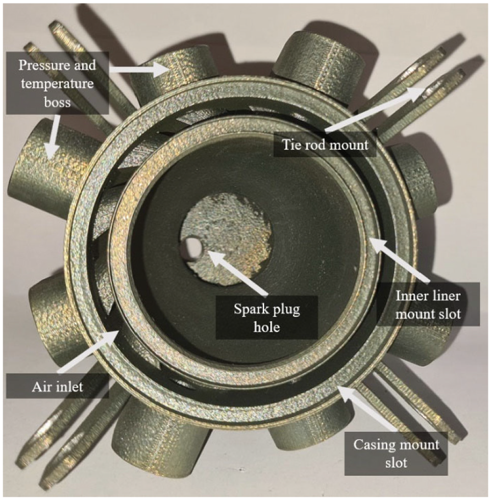
Baseline swirler.
The baseline design called for 15 holes; this was determined using the Cranfield method which stresses the importance of hole size over spacing. This method, and the alternative NASA method which emphasizes hole spacing, are explained in Lefebvre’s book. 39 Changing the number of holes alters the relative proportions of dilution and main air flows, and additional hole numbers of 20 and 10 were chosen in order to instigate a 33% increase and decrease in dilution flow, respectively.
Figure 10 shows four of the liners used during testing. From left to right, the first two are blank with 20 and 15 dilution holes respectively (a third blank liner with 10 dilution holes is not shown here). The third and fourth liners in Figure 10 illustrate the two different implementations of augmented backside cooling features, viz. offset strip fin and curved fin which, as previously mentioned, are used to investigate their secondary role as air/fuel mixing features.
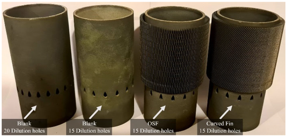
Combustor liners.
In Figure 11 the basic assembly of the combustor can be seen, showing the location of the fuel ring used for the upstream mixing tests, and the fuel inlets used for the in-vane fuel injection geometries.
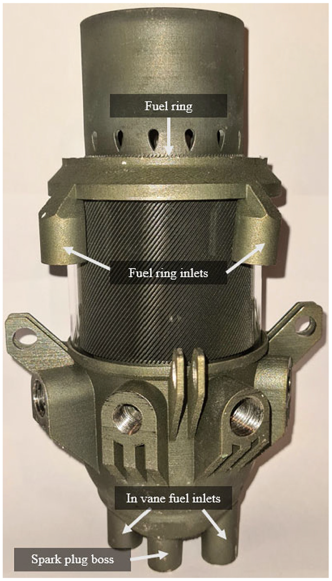
Combustor assembly.
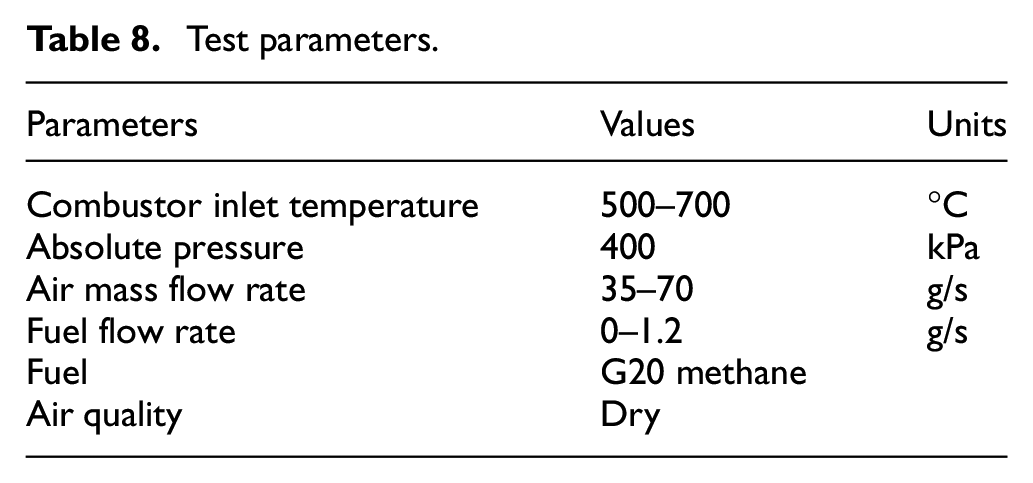
Many operating conditions were tested for the various combustor geometries – a summary is presented in Table 8. G20 test-grade methane was the fuel used, which is 99.5% ± 0.5% pure. 40 The fuel flow rate was varied for all geometries to investigate their operational limits with 1.2 g/s being the maximum flow rate achievable due to equipment constraints.
Test parameters.
Results
Geometry comparisons at variable inlet temperature and constant equivalence ratio
Tables 9 to 11 present the results of the laboratory testing, varying the inlet temperature for a constant primary zone (PZ) equivalence ratio of 0.33, for the 10 geometries tested. The inlet temperatures were varied from 700°C to 500°C at intervals of 100°C. The constant PZ equivalence ratio of 0.33 was chosen so as to provide the desired outlet conditions in terms of emissions and temperatures when operating at maximum inlet temperature.
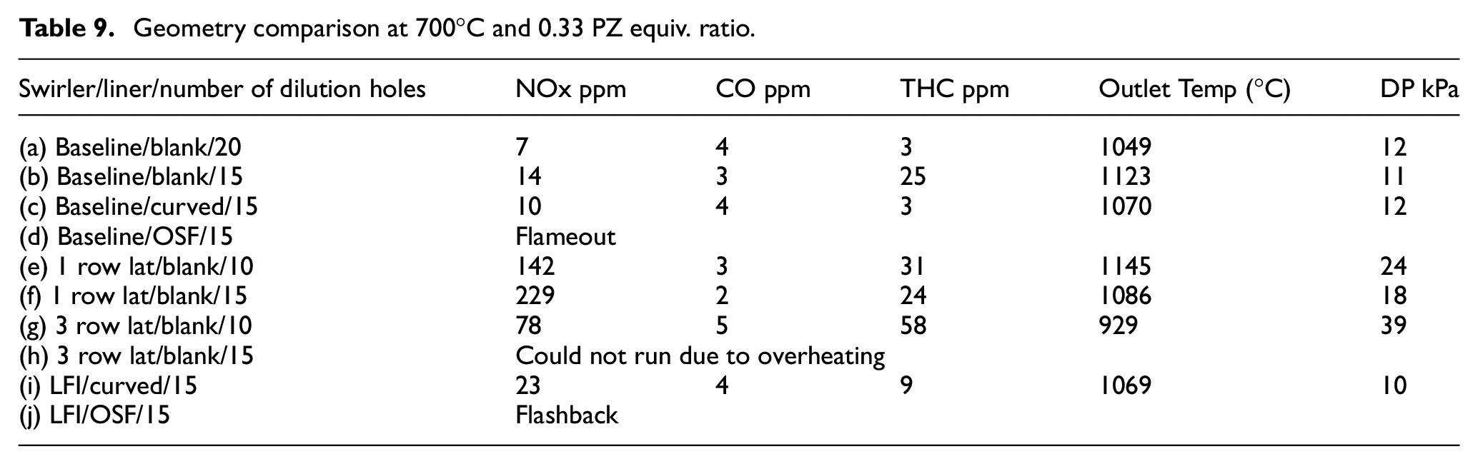
Geometry comparison at 700°C and 0.33 PZ equiv. ratio.
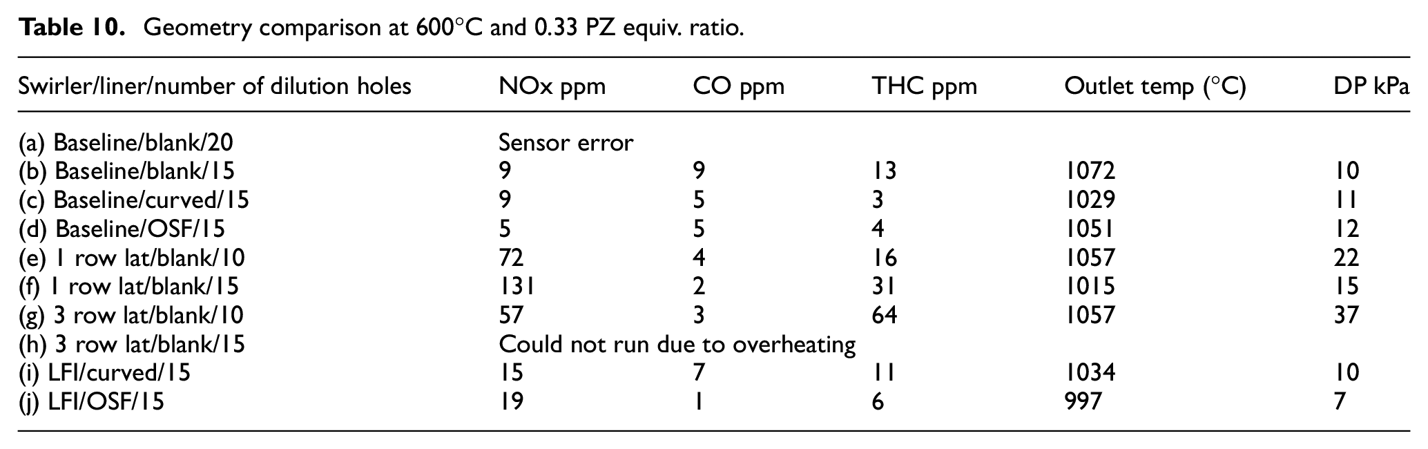
Geometry comparison at 600°C and 0.33 PZ equiv. ratio.
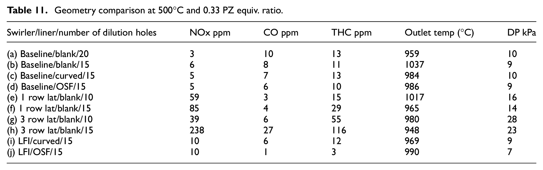
Geometry comparison at 500°C and 0.33 PZ equiv. ratio.
Since it was not possible to measure the air mass flow that was entering the primary zone, the equivalence ratios were taken from the CFD primary zone air mass flow rate predictions, which were previously determined using full-scale 3D reacting CFD in the authors’ previous publication. 41
The geometries tested had three variables: the type of swirler used, the type of liner and the number of dilution holes. The baseline swirler refers that depicted in Figure 1, while the one- and three-row lattice swirlers reference the alterations to the baseline shown in Figure 2. For the liner fuel injection (LFI) geometries a blank swirler was used, which is similar to the baseline with the exception of the removal of the in-vane injection features, since the fuel was injected upstream through the fuel ring shown in Figures 3 and 4. The liners used can be seen in Figure 10 (except for the 10-hole blank liner).
From the results at 700°C (the highest inlet temperature; Table 9) it may be observed that geometry (a) generated single digit NOx, CO and THC emissions, while the reduced dilution geometry (b) and curved liner geometry (c) achieved low double-digit NOx. This demonstrates that the AM conical swirler is more than capable of meeting the target specifications (shown Table 1) while using different combustor liners.
The reasoning for using the lattice structures, geometries (e-h), is that they would improve the fuel mixture quality via vortex generation and prevent flashback due to breakup of the wall boundary layer. AM also allows for adaptation of the lattice structures to optimize the trade-off between mixing and pressure loss, as well as the use of other lattice-type structures and surface details for different fuels and/or applications. Based on the results displayed here, however, it can be seen that they generated significantly increased NOx and THC emissions for higher pressure losses, indicating that they did not work as intended. This is thought to be due to the increased turbulence at the exit of the swirler vanes, due to the presence of the lattice structures, leading to an unstable swirling flow and the creation of hot spots, resulting in increased NOx and THC emissions. At the inlet temperature of 700°C, only the curved fin liner fuel injection geometry (i) was able to operate at the desired equivalence ratio, but nonetheless showed promisingly low levels of CO and THC emissions, although NOx emissions were higher than desired.
Three of the geometries (d, h, j) were not able to operate at this operating condition. The baseline OSF geometry (d) experienced a flameout, although at higher equivalence ratios it was operational. The LFI OSF geometry (j) with 15 dilution holes experienced flashbacks as soon as it was ignited at this operating condition. For the 3-row lattice geometry (h), the decision was made not to run at 700°C and 600°C because operation at 500°C displayed a tendency to overheat and possibly cause damage to the system. This is thought to be due to the large proportion of total air flow used for dilution, thereby reducing the air flow entering the primary zone, as well as the increased back pressure caused by the in-vane lattice features, both of which give rise to a much more fuel-rich primary zone.
Table 10 presents the results from the 600°C air inlet tests, which show similar trends to the 700°C results, but with lower pressure losses and NOx emissions, and higher THC emissions, across most of the geometries. This is in accordance with the lower combustion temperatures leading to an overall lower combustion efficiency. At this inlet temperature it was found that geometries (d) and (j) were capable of sustained operation while also producing relatively low emissions, in comparison to the other geometries. Unfortunately, there was a sensor error during the testing of geometry (a), which meant the results are not available at this inlet temperature.
In Table 11 the 500°C inlet temperature results are shown. At this operating condition all geometries were operational. As expected, lower NOx, and higher CO and THC emissions were recorded. The 3-row lattice with 15 dilution holes, geometry (h), was able to operate at this lower inlet temperature but with much higher emissions than the other geometries.
Effect of combustor design on combustion efficiency and system thermal efficiency
To assess how successful the various AM combustor designs would be in supporting the project’s overall goal of achieving 40% MGT thermal efficiency, a recuperated Brayton cycle model was used to calculate theoretical power and thermal efficiency for a typical MGT system.
The model uses the combustion efficiency obtained from the emission test results, and the outlet temperature, pressure loss and air mass flow rate measurements corresponding to each combustor design. Remaining inputs were the assumed efficiencies for the main MGT sub-systems: compressor (76%), turbine (80%) and heat exchanger effectiveness (90%). Pressure losses for the heat exchanger and ducting were assumed to be 5% and 2% respectively. All of these values are based on the industrial partners’ experience of the individual sub-systems and what they believe is achievable with further AM-enabled component development. The thermodynamic calculation was performed for an MGT operating point of 700°C combustor inlet temperature and 0.33 equivalence ratio, the results of which can be seen in Table 12. Although the test results correspond to a constant inlet temperature, this was allowed to vary in the Brayton cycle model, depending on outlet temperature and heat exchanger effectiveness, as this would better reflect what happens in a real system.
Calculated Brayton cycle power and efficiency at 700°C combustor inlet temperature and 0.33 PZ equiv. ratio for different combustor designs.
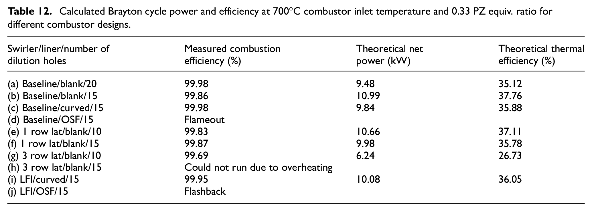
As can be seen from the Table 12 results, the three most efficient designs are: (b) the baseline design, (e) the one row lattice, and (i) the upstream fuel curved liner. It is interesting that although combustor (e) has a lower combustion efficiency and double the pressure loss of combustors (b) and (i), it still promotes a high thermal efficiency due to its higher outlet temperature. This underscores that higher outlet temperature, and consequently higher inlet temperature due to recuperation, are of greater significance than pressure loss and combustion efficiency (at least within the range experienced). This is further highlighted by geometry (g), which again has a lower combustion efficiency and a higher pressure loss, but crucially a relatively low outlet temperature, leading to a thermal efficiency of over 10% less than the rest, stressing the importance of high outlet temperatures for high thermal efficiency. This is not to say that emissions are unimportant. An AM combustor can be designed to achieve both low emission and high efficiency, as shown by combustors (b) and (i).
Due the substantial number of data recorded, the following sections will graphically present the results for the 700°C inlet and 70 g/s operating condition only, to allow for clearer representation. References to the rest of the data (500°C and 600°C at 70 g/s) will nevertheless be made and which can be found in the appendices at the end of this article.
Effect of liner changes on emissions
Figure 12 compares the performance of various liners used in conjunction with the baseline swirler, geometries (a–d), in terms of NOx, CO and THC emissions, against PZ equivalence ratio. From these results it was found that CO emissions were decreased by the dilution reduction, when comparing geometry (a) and (b), while NOx and THC emissions increased.
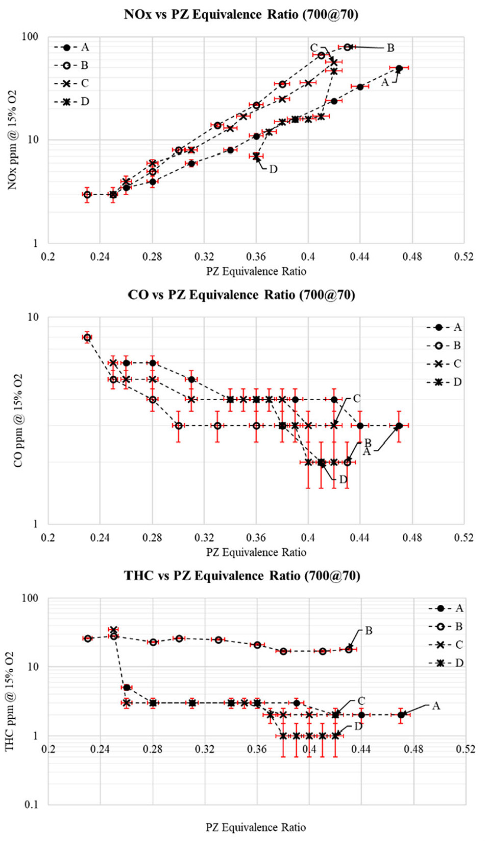
NOx, CO and THC emissions versus equivalence ratio (liners).
In Figures 12 to 14 the uncertainties associated with the emissions and equivalence ratio measurements are represented by error bars. Their calculation take into account the sensor accuracy shown in Table 7 and the deviation observed across 10 readings recorded for each operating point. The latter was 0.5 ppm for the emissions measurements, and 0.25% and 0.5% for the air and fuel mass flow rate measurements, respectively, which determine the equivalence ratio.
The curved fin liner, geometry (c), gave NOx and CO emissions comparable to geometries (b), although its THC emissions were only comparable to geometry (a). While the OSF, geometry (d), showed a reduction in THC emissions at higher equivalence ratios in comparison to the rest of the geometries in Figure 12, it also experienced a significant reduction to its lower operating range – reaching an equivalence ratio of only 0.36 at its maximum operating temperature while the rest reached lower operating limits in the range of 0.23–0.26.
At the lower inlet temperatures, which can be found in Appendix B and C, it was noticed that the NOx emissions were relatively similar, with the exception of geometry (a) at 500°C inlet temperature, which had lower emissions but showed an upwards shift in operating equivalence ratio. The CO and THC emissions at the lower temperatures were all similar between geometries (a–d), although the results for geometry (a) at 600°C are not included due to a faulty sensor while running those tests.
Effect of upstream liner fuelling on emissions
Figure 13 compares the effects of the liner fuel injection geometries against the baseline geometries (a) and (b). At 700°C inlet temperature, the CO and THC emissions of the curved fin geometry (i) tended to lie between those of the baselines but showed a propensity for higher NOx emissions. Although the OSF geometry (j) was not able to operate at 700°C, at 600°C and 500°C (refer to Appendix B and C, respectively) it was on par with the curved fin in terms of NOx emissions and showed significant improvements in CO and THC emissions. At these lower temperatures, emissions trends for the curved fin liner were similar to those at 700°C, showing an increase in NOx but CO and THC emissions comparable to the baseline geometries.
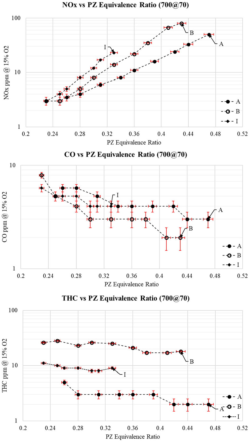
NOx, CO and THC emissions vs equivalence ratio (upstream liner fuel injection).
Noticeable also is the reduction in maximum equivalence ratio achievable with the upstream fuel injection designs due to their flashback propensity. A substantial advantage of the LFI geometries is their capability to ignite at full air mass flow, which was not possible with any of the in-vane injection designs. This suggests that a hybrid system could be implemented, using LFI for start-up and switching to in-vane fuelling for more stable operation at other fuelling conditions.
Effect of lattice structures on emissions
The final section looks at the effects of the lattice structures. From the results in Figure 14 it was evident that severe increases in NOx and THC emission were present in all the lattice structure geometries (e–h) at all operating temperatures with CO emissions remaining within the same levels for all operating conditions when compared to the baseline designs. A shift in the operating ranges was also noted, with all the lattice structure geometries being able to operate at lower equivalence ratios, with it becoming more evident at the 600°C and 500°C inlet temperature results displayed in Appendix B and C.
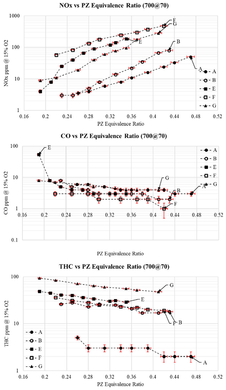
NOx, CO and THC emissions vs equivalence ratio (lattice structures).
In conclusion though, the lattice structures did not provide the desired effects of lowering emissions with gaseous fuels, although it is the authors desire to test them with liquid fuels in the future to view their effects.
Conclusion
This article presents the laboratory test results of 10 AM combustor assemblies intended for MGTs. A baseline AM swirler/injector and liner were previously generated using empirical calculations and reacting CFD modelling. Several adaptations to this baseline were then introduced to investigate their effects. These adaptations included changes to the dilution and primary zone air flow split, the inclusion of liner cooling surfaces for use as upstream liner air/fuel mixers in conjunction with the liner fuel injection ring, and the inclusion of lattice structures inside the swirler vanes.
The original intention was to test all the combustor permutations at 820°C inlet temperature, 70 g/s air mass flow, and 4 bar absolute pressure, followed by tests at reduced inlet temperatures while keeping the air mass flow and pressure constant while altering fuel flow to investigate upper and lower operating limits. Due to the limitations of the test cell, the maximum inlet temperature was reduced to 700°C. The lower temperatures were then set to 600°C and 500°C.
At first the geometries were compared at the three inlet temperatures at a constant primary zone equivalence ratio (predetermined as the desired PZ equivalence ratio at maximum air inlet temperature). This allowed the effects of different geometries on combustor operation to be compared fairly. From these comparisons the following conclusions are made:
Reduction of dilution air increased NOx and THC emissions.
Inclusion of the curved fin liner cooling surface showed a minor increase in NOx, while use of the OSF liner cooling surface significantly reduced operating range as it was unable to meet the desired equivalence ratio at 700°C and 600°C inlet temperatures.
All in-vane lattice structures showed a significant increase in NOx and THC emissions while severely increasing pressure losses proving ineffective for this type of combustion chamber.
The upstream liner fuel injecting geometries showed promise by producing comparable emissions to the baseline combustor, and in some cases outperforming it, but showed a tendency for reduced operating ranges in the form of flashback at the higher inlet temperatures (OSF liner) and flameout (curved fin liner) at lower inlet temperatures.
Calculating the effects of the various combustor designs on a 10 kW MGT system (modelled as a recuperated Brayton cycle) indicated that both the baseline swirler and the curved fin upstream liner fuelled designs should enable thermal efficiencies of over 36% with minimal emissions. And despite the one row lattice structure design recording over double the pressure losses and a lower combustion efficiency than the two aforementioned designs, a corresponding 37% system thermal efficiency highlights the importance of attaining a high combustor outlet temperature (and in turn a high recuperated inlet temperature).
Further comparisons were then made by looking at the full range of equivalence ratios achieved for each design at the three inlet temperatures while comparing the NOx, CO and THC emissions. From these results the following conclusions are deduced:
Dilution reduction showed a reduction in CO emissions but also a significantly increased in NOx and THC emissions.
The inclusion of the cooled liner surfaces reduced the operating ranges of the combustors but also produced similar NOx, CO and THC emissions, when compared to the baseline geometries.
The upstream liner fuel injection geometries proved effective at producing low emissions but also reduced the maximum equivalence ratio achievable due to the tendency for flashback.
The upstream fuelling designs had the significant benefit of being able to light off at full air mass flow compared to the rest of the geometries which required a reduction in air mass flow and increase in fuel mass flow. This was an added benefit since the main use of the fins was to coo the combustor liner. This is very useful for real-life applications since the added pressure loss attributed the cooling fins would provide a double benefit.
From these conclusions, it is determined that the application of AM to combustion chambers was successful in producing geometries effective in reducing emissions, aiding light off and reducing pressure loss. More specifically, a combination of the curved fin upstream liner fuelling for light off and the baseline swirler for variable operating conditions is recommended as a reliable combustor design for numerous applications with minimal alterations required.
Footnotes
Appendix
Declaration of conflicting interests
The author(s) declared no potential conflicts of interest with respect to the research, authorship, and/or publication of this article.
Funding
The author(s) disclosed receipt of the following financial support for the research, authorship, and/or publication of this article: The authors would like to acknowledge the EPSRC for their financial support through the Industrial CASE PhD studentship scheme (with HiETA Technologies). Award number: 1939655.