
Abstract
A new engine block with optical access has been designed and manufactured capable of running up to 3000 r/min with the same specification as the unmodified engine. The optical window allowed access to the full length of the liner over a width of 25 mm to investigate the lubricant flow and cavitation at contact point between the rings and cylinder-liner. In addition, it allowed good access into the combustion chamber to allow charged flow, spray and combustion visualisation and measurements using different optical methods. New custom engine management system with build in LabView allowed for the precise full control of the engine. The design of the new optical engine was a great success in producing high quality images of lubricant flow, cavitation formation and development at contact point at different engine speeds ranging from 208 to 3000 r/min and lubricant temperatures (30°C–70°C) using a high-speed camera. The results under motorised operation confirmed that there was no cavitation at contact points during the intake/exhaust strokes due to low in-cylinder presure, while during compression/expansion strokes, with high in-cylinder pressure, considerable cavities were observed, in particular, during the compression stroke. Lubricant temperatures had the effect of promoting cavities both in their intensity and covered ring area up to 50°C as expected. Beyond that, although the cavitation intensity increases further with temperature, its area reduces due to possible collapse of the cavitating bubbles at higher temperature. The change of engine speed from 208 to 800 r/min increased cavitating area considerably by 52% of the ring area and was further increased by 19% at 1000 r/min. After that, the results showed very small increase in cavitation area (1.3% at 2000 r/min) with similar intensity and distribution across the ring.
Introduction
Currently, internal combustion (IC) engines have found their way into a wide range of transport applications. They hold a key role in the propulsion of vehicles and are the main source of power in many industrial applications. One of the major issues with IC Engines is their pollution into our environment. The emissions control regulations introduced by governments are set to improve the air quality of the planet and engines’ performance, for example, the Euro 1 to 6 emissions targets set stringent targets on NOx, CO, HC, PM and CO2. In addition to the fuel combustion emission, the properties of lubricant oils can affect engine emissions in a number of ways as the heavy hydrocarbons from the engine oil are a significant contributor to the soluble organic fraction (SOF) or organic carbon, 1 and they also can contribute to the nuclei mode SOF, which lead to particle number emissions. 2 These can be improved by lower oil consumption through engine design, in particular, better seal compatibility to minimize leakage plus modifying oil properties. Also, the piston-ring and cylinder-liner interaction is the major source of frictional losses inside an IC engine that can lead to increased emissions and lubricant consumption. To reduce the losses and improve emission, it is essential to have a full understanding of the oil transportation mechanisms and how the phenomenon of cavitation in the oil film is affecting engine performance. Thus, the main focus of this research work is to design and manufacture an optical engine to allow optical access to the ring/liner contact point over the full length of the liner in order to be able to access and investigate lubricant flow characteristics when operating under the same conditions as those of unmodified engines.
There are a number of previous works that made use of optical engine to visualise the oil film flow in their optical engines and a summary is given by Sherrington and Smith, 3 Vasilakos, 4 who divided the measuring techniques into two major categories of optical and electrical methods. Later on, due to advance in technology, the acoustic techniques were also added. 5 The first optical engine 6 manufactured a transparent cylinder for non-firing and applied an ultra-violet light source to illuminate the oil film using a high-speed camera at 800 frames per second (fps). It followed by Sanda and colleagues7–11 who used various small quartz or sapphire windows and Laser-Induced Fluorescence (LIF) techniques to image oil films flow in their IC Engines. Investigations of Thirouard and colleagues10,11 used Laser Induced Fluorescence and a CCD Camera and confirmed that the lubrication oil fluid flow is greatly affected by the gasses that flow through the lands and piston-rings. The study of previous projects presented valuable knowledge on difficulties faced and techniques used in design of an optical engine and offered a solid background that could be used as a steppingstone.
Apart from engine research on lubricant flow, a good number of experimental studies have been carried out on cavitation behaviour and characteristics in optical single piston-ring lubricant models. Extensive reviews of all previous works in piston-ring lubricant assembly have been given by Vasilakos, 4 Ostovar, 12 Dhunput, 13 who also used different techniques like high-speed visualisation, LIF, capacitance and pressure transducers to visualise the oil film flow and cavitation formation, to measure the oil film thickness, the friction and the pressure distribution within the contact point between the rings and the liner. The recent experimental work 14 used the high-speed visualisation and a specially written MATLAB programme to quantify the effect of speed and lubricant viscosity on cavitation development. They showed fully the dynamic process of cavities development by time-resolved images from fern cavity formation to fissure cavities and then their development to the sheet and strings cavities at finally their collapse. They also showed that viscosity had a great influence on the length of cavities so that a decrease in viscosity caused a reduction in length of cavities of up to 35%, and that an increase in speed, from 300 to 600 r/min, have increased the number of string cavities and their lengths of cavities.
Although the previous experimental research at the time showed limited useful literatures and successful engine investigations on the oil film flow and cavitation, they are far from complete mainly due to lack of proper optical access. In the present work, the new designed optical engine will allow to obtain qualitative and quantitative information of lubricant flow characteristics between the piston-ring and cylinder-liner interaction area under real operating conditions with the same specification as that of unmodified engine under motorise conditions. These original and unique data not only will help to improve our understanding of lubricant flow, in particular, the cavitation formation and its development, but also, they can be used in CFD codes to establish reliable models for simulating the real time lubricant cavitating flows in IC engines, like the recent works of Wang and colleagues15,16 who used advanced cavitation models to simulate cavitation around a diesel injector’s needle valve and cavitating flow within a multi-hole diesel injector, respectively. Next section provides details of the optical engine design and its control system, followed by experimental set up and measurement method to visualise the oil film cavitation between the cylinder liner and piston rings. The results will be presented and discussed in the subsequent section and the paper ends with a summary of the main findings.
Optical engine design
Full details of the new optical engine have been given by Vasilakos 4 and here a summary of most important aspects of the design will be presented and discussed. The focus of the project has been to design a new optical engine to investigate the oil transportation mechanisms and to capture the phenomenon of cavitation as it develops on the cylinder liner when it is in contact with piton-rings. The main objective of this paper is to present the design of the optical engine and the preliminary results obtained using a high-speed camera to visualise cavitation with high quality images to help our understanding of its formation and development. In addition, for the future work, the new optical engine can be used for other optical techniques like LIF to measure the oil film thickness at contact point and fuel/air mixture in combustion chamber, and Particle Image velocimetry (PIV) to measure oil film flow velocity at contact point and spray and fuel/air mixture in combustion chamber, and Phase Doppler Anemometry (PDA) to characterised the fuel droplets velocity and size distribution in combustion chamber, and finally Laser Doppler Velocimetry (LDV) to characterised the charge motion and in-cylinder flow velocity field inside the combustion chamber.
The engine used for the testing is a Hydra model manufactured by Ricardo specifically for lab use as shown in Figure 1. This type of engine can operate with gasoline, diesel or even biofuels for both port-injected and direct-injected engine. The engine used here was a gasoline, spark ignition, port injected engine and the cylinder had a capacity of 450cc; the specific engine was a high-pressure version that can withstand pressures of up to 160 bar. This can be achieved with the use of forged piston, connection rod, crankshaft and a set of inlet and outlet valves. The engine was also equipped with the optional thermocouple modified cylinder block which can perform a full thermal analysis with the use of thermocouples installed on the liner and the piston as shown in Figure 1(b) and (c). However, this setup could not be utilised as the whole cylinder linear has to be redesigned to insert an effective optical window for optical diagnostics. For future work, it is very useful to have thermocouples on the cylinder block which offer a real time temperature distribution of the cylinder block.
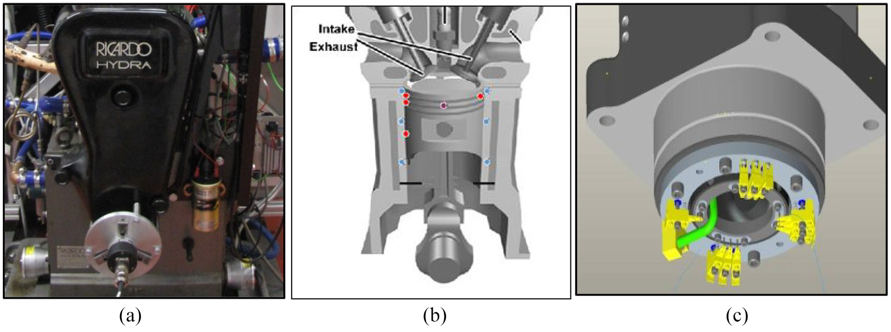
(a) Ricardo hydra engine, (b) model of thermocouples in solid cylinder block and (c) schematic of thermocouple locations on hydra engines cylinder and piston.
Cavitation is closely related to the variation of pressure and temperature within the engine and a map of the temperature and pressure distribution along the cylinder profile could give a better understanding of the cavitation along the stroke of the engine in different cycles. The possibility of obtaining real time temperature distribution readings from the cylinder block would be a great topic for futures studies and beyond the current research work. The engine has been coupled with an electric motor capable of rotating the engine at speeds of up to 3500 r/min without the use of combustion. The dynamometer has been used to start, operate and put a load on the engine.
Relevant previous work
To design the optical engine, first the recent previous optical engines that were used to investigate the lubricant flow were reviewed, which provided valuable knowledge on difficulties, challenges and techniques involved. Optical engines have been used by many researchers to investigate oil film flow phenomena at contact point in an engine by inserting a transparent window made from Quartz or Sapphire on the cylinder wall. However, there were limited literatures on the design of engines with limited success where part of the cylinder block was replaced by a transparent window and running with a full metal ring pack to investigate cavitation.
The windows on optical engines often requires constant cleaning between different runs as the fuel spray, lubricants and, in particular, the combustion deposits tend to contaminate (fouling) the surface of the optical window and reduce its optical properties. The average time before cleaning the window between the runs for a firing engine is usually less than 2 min, 17 several techniques have been developed to increase the time intervals between the cleaning of the windows. Some of the most common techniques are the use of additives, the non-firing operation, the skip firing operation or the use of a leaner air/fuel mixtures.
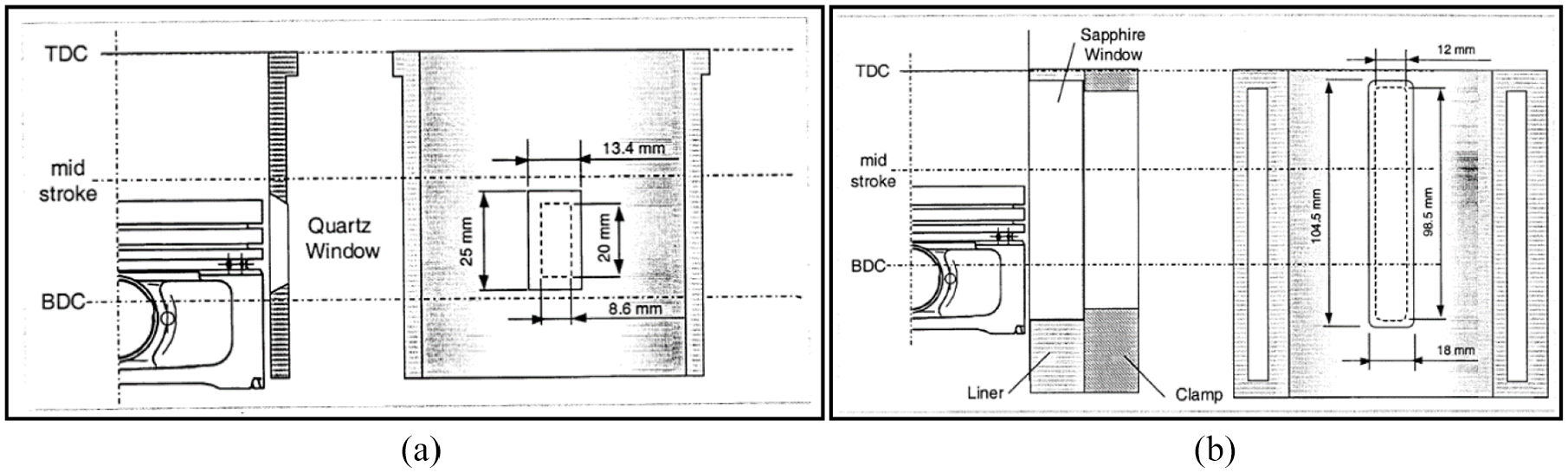
Thirouard10,11 used two optical engines, one for diesel equipped with Quartz window and the second one for a gasoline engine with a Sapphire window as shown in Figure 2. They used LIF with a CCD Camera to show effect of gas flow through the lands and piston-rings on the lubrication flow. Both engines were four-stroke and were modified by replacing parts of their cylinder with Quartz and Sapphire. The diesel engine was a Kubota manufactured EA300 model engine with a capacity of 300cc. The Kubota engine featured a single window between the mid-stroke and the BDC as illustrated in Figure 2(a). The gasoline engine was a Peugeot manufactured XUL10Ar model with a capacity of 500cc. The window extended through the full length of the stroke as shown in Figure 2(b), and it is evident that XUL10Ar optical engine is a better design than that of Kubota engine, as far as optical accessibility is concerned, with 12 mm wide over the full stroke length (96.5 mm) against that of 8.6 mm × 20 mm in Kubota engine; the Kubota window allowed for a better seal against pressure losses and a better alignment with the cylinder walls. In their designs they faced two major problems, the first was cleaning the windows as each time the cylinder head had to be dismantled and reassembled for cleaning causing huge increase in time between the runs. Secondly, since their windows were inserted from the inside of the cylinder wall, which create the risk of the window to protrude into the cylinder with catastrophic consequences for the engine.
Our objective was to introduce an optical engine with a new custom designed cylinder block to accommodate an optical window that covers the full length of the stroke over a width of 25 mm to provide a greater optical access, much greater than that given by XUL10Ar engine, to withstand all forces with and without combustion, have negligible pressure losses and to be easy to be removed and reassembled without dismantling the cylinder head. The new custom designed cylinder block was capable of rotating through 180-degree to get access to both the thrust and anti-thrust sides using the same optical window. This allows not only the full study of lubricants cavitation and oil film flow at the contact point, but also provide access to combustion chamber to allow charged flow, spray and mixture visualisation and measurements using different laser based optical diagnostics as mentioned above.
Cylinder block and window design
The design process of the cylinder block and of the windows went through several iterations. The initial design was to insert an optical window on the existing engine cylinder linear but due to water cooling system being around the cylinder it was clear that a new design has to be made for the entire new cylinder block with new optical window and a new effective cooling system within the block. The new square cylinder block, shown in Figure 3, was machined from a single piece of cast iron with the window slot on one side of the block and three interconnected water jackets (only one shown in the Figure) located on the other three sides of the block responsible for effective cooling the cylinder block while in operation or warm it up before every run up. Once the new cylinder block was machined to the exact the same specification as the original hydra block and bored to its final diameter a special honing tools was used to smoothen out the surface of the cylinder to reach the same surface roughness as the original cylinder block of the Ricardo Hydra engine. It was ensured that the new custom optical engine can stand extreme forces, temperatures and pressures, especially under firing operation, and at the same time to allow for the thermal expansion and tolerances which involved the identification of the materials that would be the best fit for the new optical cylinder. Specific considerations have been given to ensure proper matting of the optical window with the cylinder liner and the piston rings. Full details are given by Vasilakos 4 on all challenges faced and providing all limitations; here some specific highlight will be given.
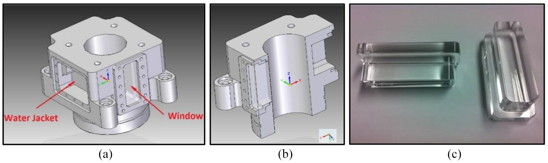
Ricardo Hydra optical-engine 3D final design: (a) new cylinder linear with optical window and cooling water jacket, (b) design cut-out and (c) manufactured Quartz widows.
The Perspex is a strong, lightweight, cheap, easy to machine with a very good optical clarity for visualisation that can be used for motorized condition but has no use for firing cases. Quartz and Sapphire were found to the best choice with exceptional optical clarity, hardness and thermal capacity, especially in case of the Sapphire. However, the overall cost of Sapphire is three times that of Quartz and considering that the engine needs several of them during the project, especially under high load and firing conditions, then the Quartz was deemed to be a more viable solution, and with its excellent optical clarity and physical properties made it an ideal choice for use in an optical-engine.
The final design of the cylinder block with new windows is shown in Figure 3. Initially, the optical window was designed to offer a distinct feature with tapered window sides and matching housing sides compared with rectangular sides. These matching tapered sides would allow for a greater matting surface between the window and the cylinder liner which would also offer a much greater seal. However, after many close discussions with window manufacturers it was found this will raise serious problems achieving the required tolerances on the chamfered edges which means discrepancies between windows that may lead their protrusion within the cylinder. The final window compared with the initial design featured parallel side surfaces and 90° angles, as shown in Figure 3(c), the outer flat side of the window has a flange type feature to ensure good sealing between the window and cylinder. These features are much easier to be manufactured and ensured a better consistency between the windows. It should be noted that once every window and window housing were placed onto the cylinder block they were re-honed to ensure perfect fitting (by checking the tolerances around the bore and window during the process), and also to preserve the surface roughness between the piston ring and cylinder liner. The problem of access to the thrust and anti-thrust side was solved by considering a new design for the mounting holes of the cylinder block so that it can be rotates through 180-degree to get access to both the thrust and anti-thrust sides.
Another common problem with optical engines was the widow fouling with a time interval usually range from 30 s to 2 min, in particular with firing runs. Opening the cylinder head was not an option as this operation was very time consuming and required more than one person to perform. For that reason, a mechanism was manufactured, and a methodology established that allowed for the safe removal of the windows and their reassembling while ensuring no pressure loses, no damage to the window and avoiding windows protruding into the cylinder. In addition, the minor dimensional differences between the different windows can be eliminated with the use of custom made housings from steel,which is an easier material to machine than quartz. These housings would be machined internally to fit each of the individual windows, which would accommodate for the slight windows inconsistencies and on the outer side they could be made at a very tight tolerance to fit the cylinder block ensuring no leaks occurred. Since the housings are custom made for each individual window, each window has been glued onto the housings to give an extra security against the leaks. Figure 4 shows examples of those housing components along with the way that the windows were secured inside the housing and how it was fitted onto the cylinder block.
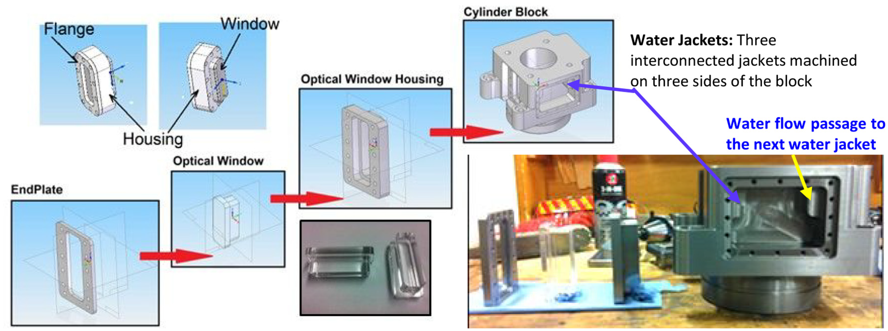
Window, window housing, flange and cylinder arrangement for assembly.
The matting of the cylinder with the Quarts was also a major issue with the design of the optical engine. The use of the new custom housings helped to achieve a very good fit. When the windows were glued within their housings and they were machined again with the cylinder block once they were all assembled together ensuring perfect matting of the window, the housing and the cylinder. The housings also feature four additional corners holes to assist their removal and installing the housing assembly easily for cleaning the windows between the test runs. Figure 4 also show the internal flow passage for connecting the three cooling water jackets that were machined on the three consecutive sides of the cylinder block, as explained before.
There are many piston-rings commercially available and each is suitable for a variety of different applications. However, in the present investigation, one of the core objectives was to use as many of the Ricardo engine components in their original form as possible in an attempt to produce results that would be as close as posible to the operation of an unmodified engine. Thus, it was decided to use the ring setup with standard configurations that was supplied originally with the Hydra engine, which was also used with the unmodified engine for all other performance and related parametric tests. Figure 5 shows the arrangement of the three rings on the piston and their supplied detailes and profiles; the size of the first two rings (compression beveled and middle rectangular rings) is 2 mm and the third ring (oil control ring) is 4 mm. Finally, since the piston-rings have the tendency to rotate inside their groves, as confirmed from our observed visualisation. The rings could have been pinned from inside their groves as shown in Figure 5 together with a magnified image of the piston-ring assembly from the optical engine on which the locations of the three rings are shown. However, in the current investigation, the piston-rings were not pinned, but this feature could be added at a later stage if ring rotation was proven to be an issue.
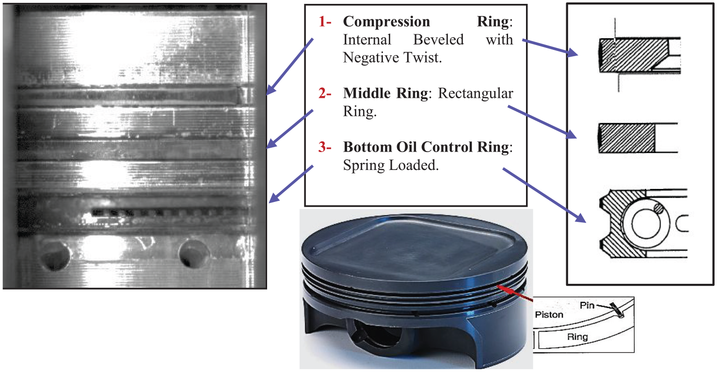
Ricardo hydra optical-engine piston-ring profiles and its magnified image from optical engine.
The entire control system to operate the engine has been redesigned with new software so that the ECU was capable of controlling not only the operation of the engine, but also the optical equipment that were later installed. Two National Instruments PCI cards were installed on a lab desktop computer; one card for acquisition and the second for processing. The signal processing on the computer was possible with the use of LabView. Three pieces of software had to be designed for the needs of the engine control such as firing and injection. By taking input signals from two main sensors, the crank shaft encoder and the cam shaft encoder; the signals collected by the two cards were then processed, and new signals were sent back to the engine. In addition, the software was designed to send out another two additional signals that would control the optical equipment like triggering the high-speed camera at a specific crank angle (CA) and the second to drop the intensity of the light source right after the camera would stop recording; full details are given in Vasilakos 4 including the engine control and acquisition software.
The new optical engine was initially tested under motorised operation using an electric motor connected onto the engines crank shaft as it is much safer (at significantly lower operating pressure and temperature) than under firing condition to assess the new optical engine’s capabilities and to identify any faults that might have slipped during the design phase. Once the engine has been rigorously tested and finely tuned the next step was to continue testing under skip-firing operation when the fuel is not ignited in every cycle. The tests started by skipping four cycles for every one that fired and that continued until the engine reached fully firing operation. Similar path has been followed to bring the engine at its maximum operational speed. Some results of these testing are shown below in Figures 6 and 7 where typical in-cylinder pressure trace and imaging of cavitation are shown, respectively.
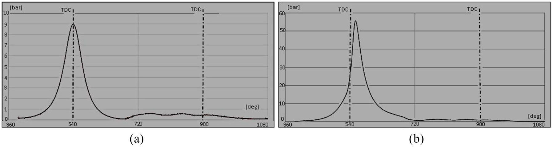
In-cylinder pressure trace as a function of CA at 1000 r/min and 70°C: (a) motorized and (b) firing.
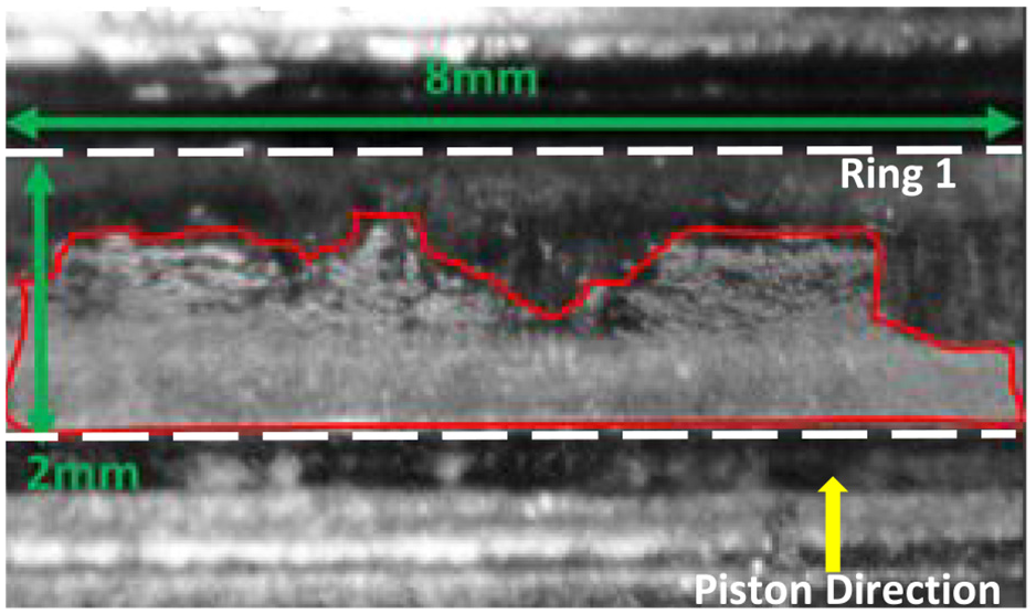
The cavities on compression ring (1) during the upstroke at 800 r/min and 30°C.
The pressure trace was consistent throughout the experiment provides repeatable values with peak pressures of 9 bar for motorised case at TDC and 56 bar for firing case a few degrees after TDC because in the firing case the fuel does not fully combust at the TDC. The images of cavitation were of good quality with relatively high resolution so that a script programme written in Visual Basic can be used to calculate the area of cavitation for each of the different frames as shown in Figure 7, the area bounded within the red border over the compression ring (Ring 1); more results will be presented and discussed later in the results section.
The combined new control system and the optical engine would offer a very useful and valuable testing device that would allow further investigation to be carried out on the cavitation within a fully firing optical-engine, and beyond. The new optical engine has a window that covers the full length of the liner over a width of 25 mm and provides full access to the very hostile area where the piston-ring and the cylinder-liner interact with each other and, in addition, a good exposure to the combustion chamber where the charged motion, spray characteristics and fuel mixture can also be visualised or quantified using different optical diagnostics like LDV, PIV, PDA and LIF as used by Yan and colleagues.17–21
The results presented here have been chosen in a way to improve the understanding of lubricant flow and cavitation that take place at the contact areas between the piston rings and cylinder liner inside an IC engine. In brief, cavitation in lubricant film at around the contact point occurs when the lubricant pressure is below saturated pressure as it passes through the narrow gap, which initiates the phase change process and produces lubricant vapour. At the same time, cavitation can also happen when the dissolved air/gas are released from within the lubricant volume when the pressure of lubricant decreases. 13 In general, cavitation in lubricant occurs in the form of bubbles that would collapse when the surrounding flow pressure is recovered. Usually the collapse of bubbles is followed by a release of energy which can locally damage nearby components. In addition, cavitation would also affect the primary function of the lubricants.
One of the other phenomena that have a significant impact on the engine’s emission, performance, efficiency and reliability is the lubricant blow-by phenomenon, which is related to the release of fuel/air mixture and lubricants through the ring gaps and also contact point between the rings and the liner; this phenomenon will be investigated in the next phase of experiment. In brief, blow-by can occur due to insufficient ring-assembly of the engine design and poor lubricant performance, in particular, when gas cavities form at the contact point due to intense cavitation. Observation by Duszynski, 22 Inagaki et al., 23 showed how the blow-by can occur, either be lubricant passing the piston-rings and entering the combustion chamber or fuel and combustion products passing down the rings and entering the crankcase. Both are highly undesirable as the presence of lubricants in combustion chamber has a negative impact on the output emissions while the unburnt fuel and exhaust gases in the oil sump contaminate the lubricants and therefore greatly affects its performance. 22 The presence of lubricant in combustion chamber would produce a significant increase in the particles emitted with sizes larger than 50 nm as reported by Amirante et al. 24 In addition, it has been reported 25 that the lubrication performance in terms of the distribution of oil film pressure, thickness and bearing thermal loads has been improved when the main bearing cap is made of iron instead of steel.
Experimental set up and instrumentation
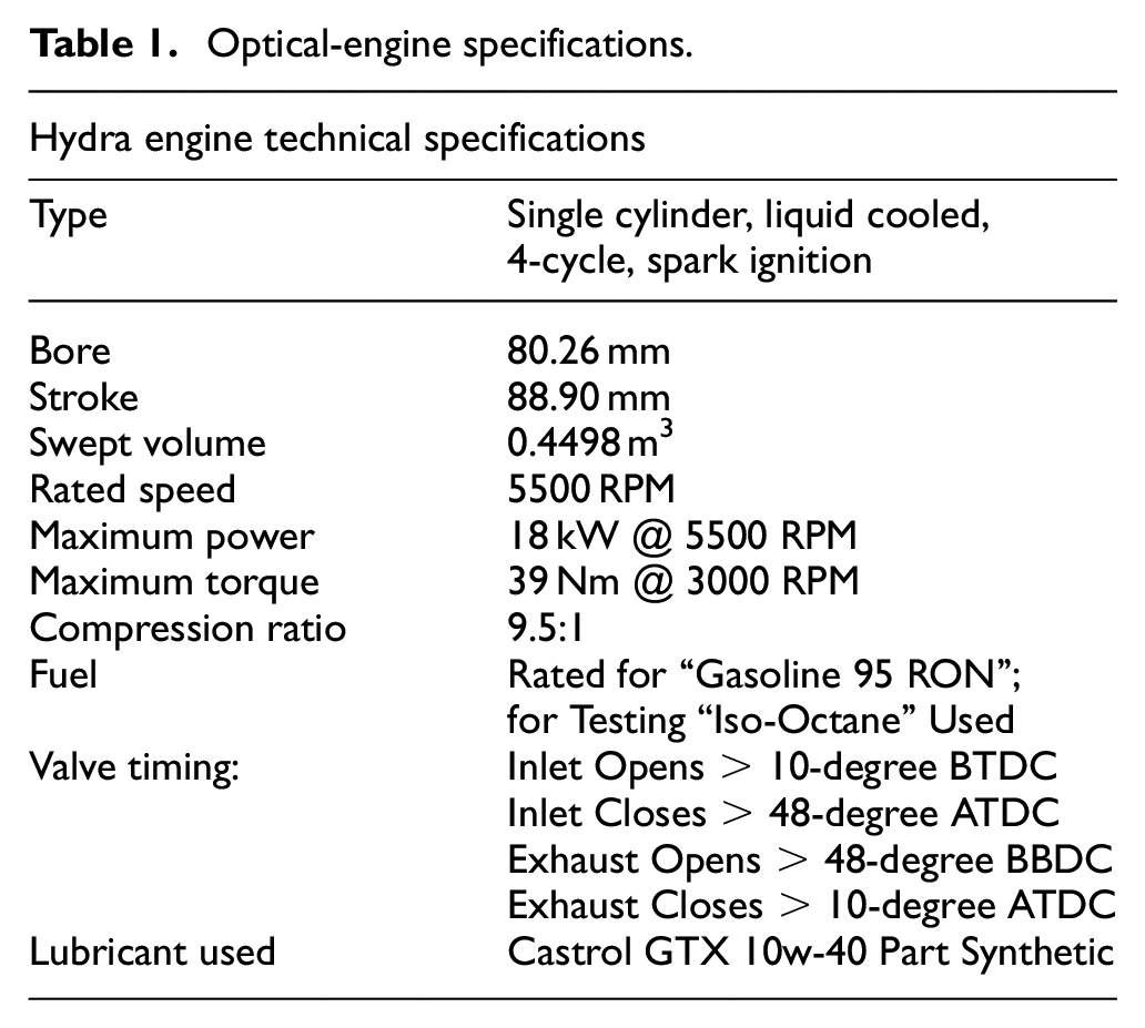
The testing of the optical engine generated a large amount of information in the form of visual data and a representative sample of these data have been presented here. The specifications of the engine are shown in Table 1. The lubricant used is Castrol GTX 10w-40 with a density and kinematic viscosity of 866 kg/m3@15°C and 98.9 mm2/s @40°C, respectively, and has a flash point at 204°C.
Optical-engine specifications.
The visualisation of the lubricant flow between the piston ring and the cylinder walls was performed using a high-speed camera and appropriate lighting. The camera has been fixed on the thrust side of the engine on an optical rail traverse (fully adjustable in 3-D) to be able to align the camera with optical window so that lubricant flow can be imaged under motorised and firing conditions. The images were captured by a Photron Fastcam SA1.1 high-speed camera equipped with Nikon 125 and 50 mm lenses, which has a 12-bit dynamic range and shutter speed down to 1 µs. It provides 5400 frame per second (fps) for the full resolution of 1024 × 1024 pixels, but the faster frame rate can be achieved for smaller resolution, for example, a frame rate of 67,500 fps for a resolution of 256 × 256 pixels.
The use of high-speed cameras for the visualisation of the lubricant flow requires high-intensity light-sources to be able to capture the changes in the fluid flow within very short period of time. Two high-power ARRI lamps, each with 250 W power output, have been used for lighting. The ARRI lights are commonly used in stadiums, arenas and theatres, and as a result they usually offer a very wide focal point. In this application where the window is only a few centimetres wide the light would have to be coupled with two focussing lenses to produce a collimated beam, which helped to guide the high intensity light onto the area of interest on the window. The light source assembly was fixed on an adjustable rail, fixed on the same traverse, which allowed for the correct alignment of the light with the lenses and offered the freedom to adjust the distance between the two lenses and the light source. The entire assembly was mounted onto a lathe bed traverse weighting 350 kg to ensure stability. The installation of an optical rail was designed and manufactured in such a way to be used in the future for other lasers diagnostic techniques like LIF, PDA and PIV techniques.
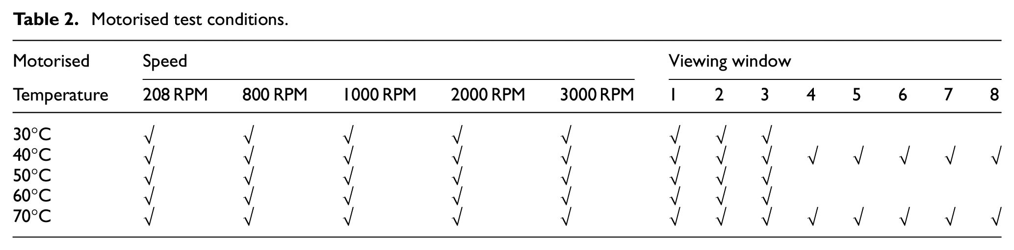
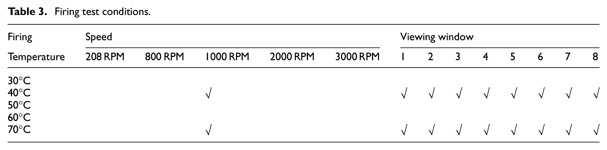
The map of camera views with regard to the optical window is shown in Figure 8, which identifies the areas where the images ca taken with the main focus on areas 1 and 2 related to the top half and bottom half of the optical window and the corresponding zoom-in areas of 3 and 4. Tests have been performed for both motorised and firing conditions as highlighted by the X sign in Tables 2 and 3, respectively, together with the details of the mapping areas investigated. The motorised tests followed the entire matrix while in the case of the firing limited tests were performed, as in the firing operation, the combustion products would cause the optical window fouling due to the build-up of combustion residuals.
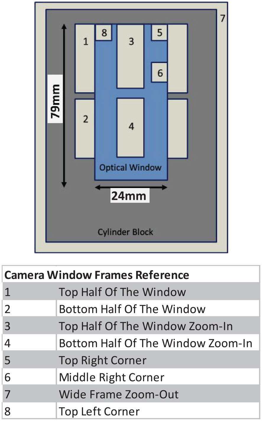
The camera positions used for capturing the visual data.
Motorised test conditions.
Firing test conditions.
Results and discussions
The presented results are under motorised operating conditions. From the initial tests, the first interesting observation was to notice that the cavitation was only occurring in some strokes within the four-stroke IC engine. Detailed observations, after going through all videos, confirmed that no cavitation occurs during the intake and exhaust cycles between the cylinder-liner and piston-rings (all three rings) interaction at either the up-stroke or down-stroke of the piston; at least they were not visible or detectable by the high-speed imaging equipment even when using the zoomed set up imaging. In order to clarify this, further testing was performed with the use of florescence additives and no fuel spray injection (to avoid window fouling) at an engine speed of 1000 r/min and the lubricant temperature of 70°C. The results confirmed that there was no cavitation as clearly evident from Figure 9 where it shows the lubricant flow −37° before TDC (BTDC) in exhaust stroke and +47° after TDC (ATDC) in intake stroke over all three rings of 1, 2 and 3 as highlight on the Figure. Further testing under firing condition also confirmed the same result. Full detailed explanation of all tests with images are presented and discussed in Vasilakos 4 and here a brief summary is given below. It should be mention that the clear images with high resolution of the piston-ring assembly (all three rings on the same image) presented in Figure 9 display the capability and benefite of the new optical engin.
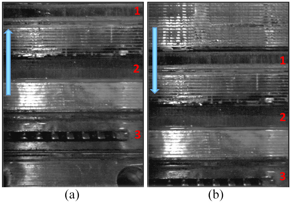
Images at BTDC (up-stroke) and ATDC (down-stroke), 1000 r/min, 70°C, motorised: (a) −37 deg BTDC, exhaust and (b) +47 deg ATDC, intake.
The absent of cavitation during the intake/exhaust cycle can be partially due to the fact that the in-cylinder pressure within these two strokes is close to the atmospheric pressure with negligible pressure difference across the rings which may not allow for the cavities to generate and grow as the lubricant pass through the contact point; it should be noted that oil film motion in these two strokes is dominated by the piston-ring movement only, and the results suggest that the strength of this movement was not enough to bring down the lubricant pressure across the rings to its critical level for it to cavitate. Another possibility, which is believed to be the main cause and related to the above, is the gap between the rings and the liner. The piston-rings are designed on the principle that the in-cylinder pressure assists them to seal better with the liner. The higher the in-cylinder pressure the higher the force acting behind the piston-rings and thus a better seal, which, in turn, forms a smaller oil film between the rings and liner. This suggests that the oil film thickness (clearance) during intake/exhaust cycle is larger than that of the power cycle (compression/expansion), as a result, the lubricant during the power cycle with smaller clearances needs to squeeze through with higher velocity and therefore lower pressure.
On the other hand, during the power cycle where there is a massive increase in the in-cylinder pressure, the real time video imaging of lubricant clearly shows the presence of cavitation at contact points in-between the cylinder-liner and piston-ring interaction at both the up-stroke and the down-stroke of the piston. Figure 10 depicts images that have been captured during power cycle (Figure 10(b) and (c)) under motorised conditions without fuel injection at 1000 r/min and a lubricant temperature of 70°C and are compared with that of the exhaust cycle of Figure 10(a). Comparison of images of exhaust up-stroke and compression up-stroke at the same crank angle BTDC clearly shows extensive cavitation on all rings with compression stroke, particularily on rings 1 (compression) and 2 (rectangular). Similar level of cavitation is evident during the expansion down-stroke on all rings, Figure 10(c). As explained, this is directlely related to the much higher in-cylinder pressure during the compression and expansion strokes that forces the oil film go through the ring/liner clrearance gap much faster and therefore produce greater pressure drops to below the critical value for cavitation. The presence of cavitation at other crank angles BTDC and ATDC has also been observed (full details are given by Vasilakos 4 and not presented here due to the shortage of space) and confirm similar observation as presented in Figure 10.
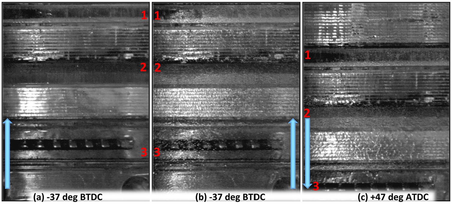
Comparison of images between the exhaust, compression and expansion strokes at 1000 r/min, 70°C, motorized: (a) exhaust stroke, (b) compression stroke and (c) expansion stroke.
The dynamics of these cavitation and their structures are more clearly visible when viewed through the recorded videos compared to those viewed from the zoom-out photos presented here in Figures 9 and 10, which show all three rings on the same image; for analysing the behaviour of cavitation with small structure magnified and zoom-in images are required similar to those presented in Figures 11 to 14. For example, to have a better view of cavitation structure and the impact of in-cylinder pressure, the images of Figures 11 and 12 are presented and compared in magnified forms, which show the cavitation during the compression and expansion strokes, respectively, on compression ring 1 at two different CAs and therefore two different in-cylinder pressures. In the up-strooke compression, Figure 11, the cavitation intensity is clearly higher near the TDC (−37° BTDC, Figure 11(b)) where the in-cylinder presures are higher than that at −61° BTDC, Figure 11(a), with lower in-cylinder pressure. It is also evident that the cavitation bubble clouds occupies a large part of the area of the ring nearer to TDC with more intensity towards the lower edge of the ring, as would be expected since the oil film flow direction is downwards from top to bottom edge opposite to piston-ring movement. The cavitating bubbles are initiated in a uniform structure near the lower edge of the ring and that as they are convected towards the top edge of the ring they start to break up or collapse with less intensity; similar to that obsereved by Dhunput. 13
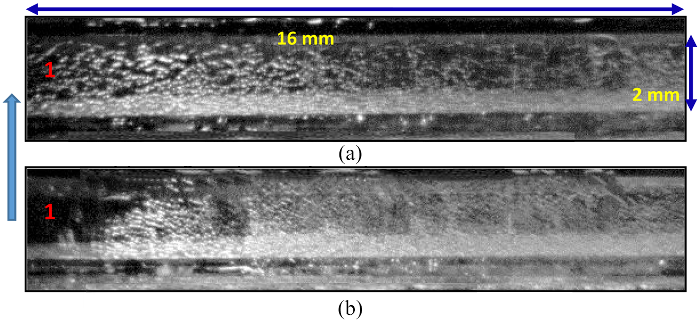
Cavitation images on ring 1 during compression up-stroke at 1000 r/min, 70°C, motorised, at different Cas: (a) −61° BTDC; low in-cylinder pressure, (b) −37° BTDC; high in-cylinder pressure.
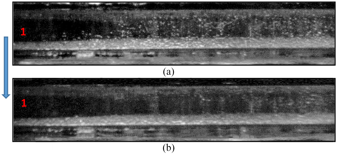
Cavitation images on ring 1 during expansion down-stroke at 1000 r/min, 70°C, motorised at different Cas: (a) +47° ATDC; high in-cylinder pressure and (b) +59° ATDC; low in-cylinder pressure.
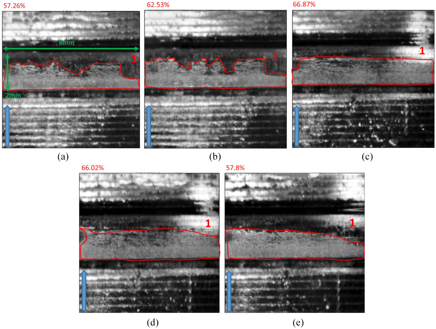
Cavitation images on ring 1 during compression up-stroke at 800 r/min, motorised at different temperatures: (a) 30°C, (b) 40°C, (c) 50°C, (d) 60°C and (e) 70°C.
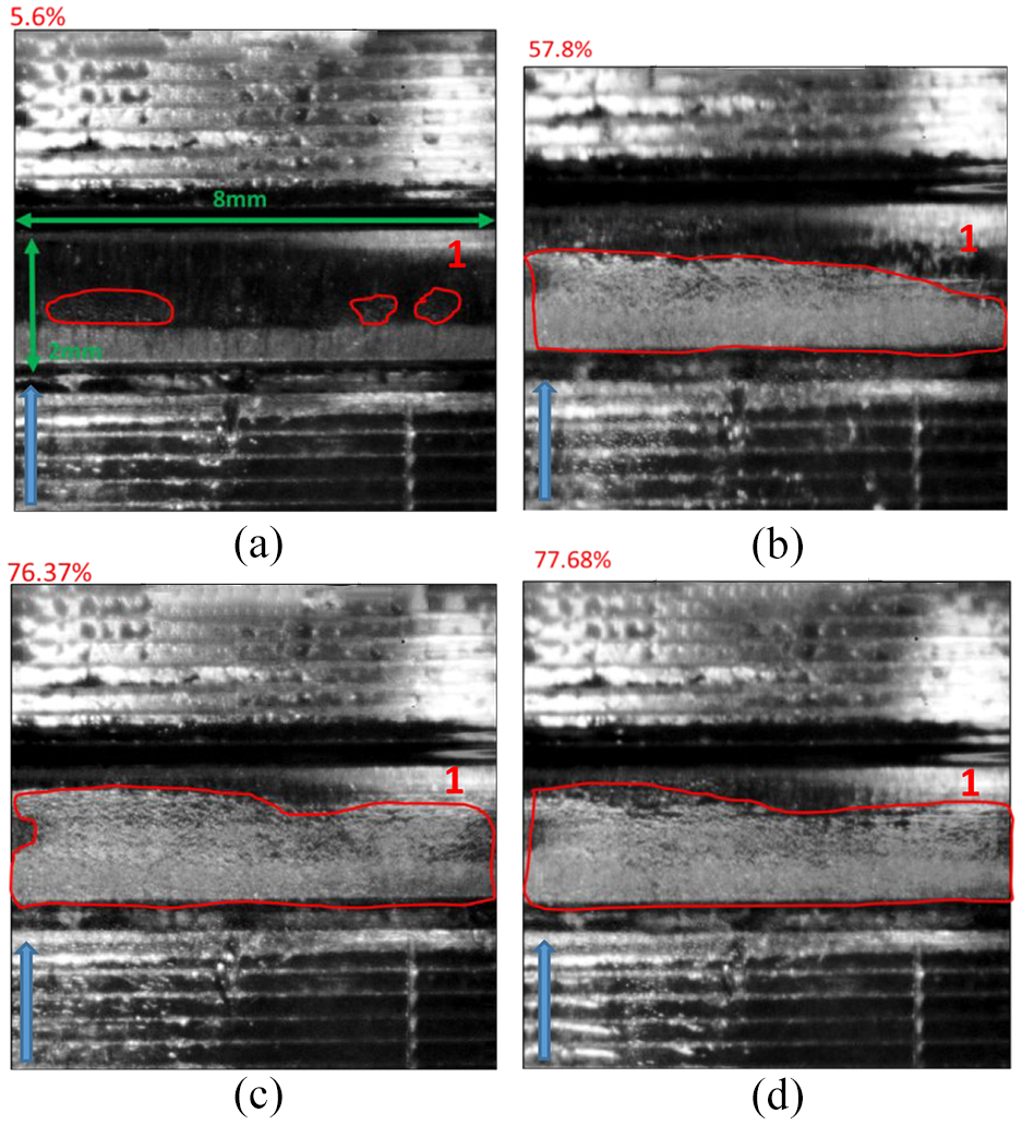
Cavitation images on ring 1 during compression up-stroke at 70°C, motorised at different temperatures; (a) 208 r/min, (b) 800 r/min, (c) 1000 r/min and (d) 2000 r/min.
Similar results can be seen in the down-stroke expansion, Figure 12, with similar structure but at reduced cavitation intensity. For example at +47° ATDC of Figure 11(a) and +59° ATDC of Figure 12(b) where the in-cylinder presures are almost similar, the intensity of the cavitation is much higher during the up-strooke compression. The reasone for this is mainly due to the relative direction of the piston motion (up or down) movement with the in-cylinder pressure action line which is always downwards. That is to say that in case of up-stroke compression the piston direction is opposing to the in-cylinder pressure, which results in much larger relative velocity/acceleration of the lubricant through the gap, which in turn cause more pressure drops across the rings, and thus more cavitation. This process is reversed in the case of down-stroke expansion with the piston motion and in-cylinder pressure acting in the same direction and therefore lower lubrecant velocity or less cavitation.
It is interesting to note that the presence of cavitation in Figures 10 to 12 is more pronounced in the lower half (downstream) of the piston ring for both compression and expansion strokes and in the same direction with that of the in-cylinder pressure. Considering the the absentees of cavitaion during the intake and exhaust strokes, as explained above, and the influence of in-cylinder pressure during the compression and expansion strokes, it can be suggested that, within the measured range, the occurance of cavitation is mainly controlled and dominated by in-cylinder pressure rather than the piston-ring movement, while the piston-ring motion affects the intensity of cavitation.
In order to show the effect of the temperature and the engine speed on cavitation bubble more clearer, new set of zoom-in images with better resolutions have been taken and are presented below in Figures 13 and 14. The effect of the temperature on cavitation on ring 1 is shown in Figure 13. The given temperatures are the measured values at the inlet of the coolant before it enters the water jackets in the engine cylinder head/liner assembly. These temperatures are maintained with the use of the cooling and heating control systems of the engine. In this study, when the engine is not fired, the lubricant temperature can be assumed to be similar to that of the cooling temperature, although there are added heat by compression and friction; considering the runing period for the recording images is short, it would be reasonable to take the above assumption, at least it provides an undrestanding of changes in cavitation structure with the relative change of temperature. It has been reported that cavitation is directly linked to the viscosity of lubricants/liquids and the viscosity is highly depended on the temperature.13,26 In a lubricant model investigation, 13 the increase in temperature resulted in decrease in oil film thicknesses, lubricant viscosities and advanced the initiation of the cavitation and enhanced its intensity. Similar results were obtained in a model multi-hole injector 26 using glycerol at different temperatures and showed that an increase in temperature had the effect of enhancing cavitation due to lower viscosity and weaker molecular bounding. So, the following images, Figure 13, show the difference in cavitation levels at different temperatures for the same lubricant (BP Castrol GTX 10w-40), at the same speed of 800 r/min and at the same CA.
Although the cavitating bubbles are clearly visible at all temperatures, the differences in the cavitating areas at different temperatures are not that evident by naked eye as their shapes change from one frame to the next. For this purpose, a script was written in Visual Basic that would calculate the area of cavitation for each of the different frames. In Figures 13 and 14 the values of the calculated area by the software is given in red on the top left corner of each image and the bounded cavitating area by red line. The area is given as a percentage of the entire ring visible on the same frame. Although, the ring appears to be of a flat rectangular shape, it is actually not. The ring has a circular profile and the centre of rotation is along the vertical axis in the middle of the frame. A calculation based on square meters or square centimetres would not be accurate as there would be a difficulty when bringing the curvature of the ring into the calculations. The most appropriate representation that would carry the minimum risk and offer maximum accuracy is to represent the area of cavitation in a percentage of the total ring visible on the frame. In this way, the calculations are ensured to be accurate while still maintaining a solid measure of comparison between the different frames.
In Figure 13 the calculated cavitating area at 30°C covers 57.26% of the total ring area while it is 62.53% at 40°C, an increase of 5%. Since the speed, CA and the type of lubricant are all the same, this difference is directly linked to the increase of the lubricant temperature. The corresponding percentage of the cavitating areas at 50°C, 60°C and 70°C are 66.87%, 66.02% and 57.8%, which give an increase of 9.6%, 8.8%, 0.5% in the cavitating areas, respectively. The results at all temperatures clearly show that the cavitating bubbles are initiated in a uniform structure near the lower edge of the ring similar to that seen in Figure 11, however, as they move towards the top edge of the ring they start to break up and form an unstable cavitation structure for up to 40°C with uneven shape across the ring area. The change in cavitation shape from 40°C to 50°C takes a crucial step, where the cavitation bubbles start showing uniformity as far as their shape is concerned so that at 50°C a uniform rectangular area across the ring is evident with no unevenness in cavitation structure near the top edge as seen at lower temperatures; this uniform cavitating area continues to be present at 60°C and 70°C.
It is interesting to note that the cavitating area increases up to 60°C as expected and in agreement with previous works, but after 60°C, the cavitating area starts to decrease unexpectedly so that the cavitating area at 70°C (Figure 13(e)) reduced by 8.3% to 57.8% compare to that at 60°C and it is almost the same as that at 30°C, Figure 13(a). However, it is also evident that the cavitation intensity at 70°C is higher and denser than all other lower temperatures, which is in line with expected trend of getting more cavitation when temperature increases, that is, drop in lubricant viscosity. The reason for the decrease in cavitating area after 60°C may well be due to the higher level of cavitating bubbles’ burst or collapse at higher temperature, especially away from their point of generation. The results suggest that although the cavitation is enhanced with temperature, there is a critical temperature (around 60°C) beyond which the cavitation bubbles starts to collapse.
Figure 14 show the effect of the piston speed on cavitation at the same CA and lubricant as used in Figure 13, and a temperature of 70°C. Starting with a very low engine speed of 208 r/min where there is almost no cavitation with very small visible pockets of cavitating bubbles with an area of around 5.5%, while at 800 r/min the cavitating bubbles have been increased considerably covering 57.8% area of the ring with a uniform distribution; this was expected because as the engine speed increases then the piston-ring moves faster, which causes the oil film move with higher velocity and therefore lower pressure or higher cavitation. The cavitating areas increased further to 76.4% and 77.7% at engine speeds of 1000 and 2000 r/min, respectively. Although the large differences between the 208 and 1000 r/min are obvious, it seems that there is little to no effect by the increase in engine speed from 1000 to 2000 r/min with similar cavitating areas and also similar distribution and intensity; the results at 3000 r/min, not presented here, was also similar to that of 2000 r/min. This suggests no or little dependency of cavitation on piston speed beyond 2000 r/min.
Conclusions
A gasoline optical engine has been designed and manufactured capable of running up to 3000 r/min with the same specification as that of the unmodified engine under motorise and firing conditions. The distinct key features of the new optical design were the manufacturing of a new custom cylinder liner block with effective cooling system and the new optical window with its new custom housing. The new cylinder block was capable of rotating through 180-degree to get access to both the thrust and anti-thrust sides using the same optical window. The new optical window housing covers almost the full length of the liner over a width of 25 mm allowing full access to onto the ring/liner contact point. In addition, the new window houssing allowed to eliminated the minor differences in windows manufacturing, to ensure perfect matting of the window, the housing and the cylinder, to eliminate leakage and pressure loss, to easily removed and reassembled the window for cleaning without dismantling the cylinder head. A new custom engine management system has also been designed with build in LabView, which allowed for the precise control of the engine and of all the auxiliary systems such as fuel, ignition, sensors and optical equipment. Overall, the design of the new optical engine was a great success in producing high quality images from the usually inaccessible piston-ring and cylinder liner interaction and it would offer a useful and valuable testing device. This unique design not only allowed to investigate a number of lubricant phenomena around that specific area like oil transportation, cavitation and blow-by, but also provides sufficient access to the combustion chamber to allow flow and spray visualisation, flame propagation using different optical methods like LDV, PIV, PDA and LIF.
Cavitation formation and development at ring/liner contact point in the optical engine have been carried out under motorised at different engine speeds (208–3000 r/min) and lubricant temperatures (30°C–70°C) using a high-speed camera coupled with two ARRI high power sources. Below provides a summary of the main findings:
The results confirmed that there was no cavitation within the gap of the ring/liner contact point during the intake/exhaust strokes due to low in-cylinder pressure (atmospheric) with little pressure difference across the ring and widest oil film thickness in the gap. Thus, the oil film flow motion driven by the piston-ring movement was not strong enough to reduce lubricant pressure to the required level for cavitation to take place. This was confirmed at all speeds and temperatures investigated even under firing condition.
During the compression and expansion strokes with high in-cylinder pressure, massive cavitation bubbles have been observed at the contact point of all rings and that the intesity of the cavitation increased near the TDC where the in-cylinder presures are higher. It was also observed that the intensity of cavitation bubbles during the compression stroke was much denser than those during the expansion due to higher relative motion of the piston-ring with the in-cylinder pressure line of action resulting in a more pressure difference across the rings during the compression stroke. In addition, the results, within the measured range, showed that the occurance of cavitation is mainly controlled and dominated by in-cylinder pressure rather than the piston-ring movement.
The results at different lubricant temperatures for the same lubricant and at the same speed and CA, showed that the cavitating area increased with temperature as expected so that at 30°C it covers 57.26% of the total ring area which increased to 66.9% at 50°C, an increase of 9.6%, and then it starts to reduce gradually to 57.8% at 70°C, similar to that of 30°C but with much higher intensity. The latter unexpected reduction may well be due to the higher level of cavitating bubbles’ burst or collapse at higher temperature.
Similarly, the increase in piston speed (for the same temperature, CA and lubricant) enhanced the cavitation so that the cavitating area at 800 r/min was 57.8% of the ring area with a uniform distribution, and then increased to 76.4% at 1000 r/min, a jump of 19%. The results between 1000 and 2000 r/min showed a very small increase in cavitating area by just 1.3% with similar intensity and distribution across the ring. This may suggest no or little dependency of cavitation on piston speed beyond 2000 r/min.
Footnotes
Acknowledgements
The authors would like to thank BP and EPSRC for funding this research work. We also would to thank Dr M Gold and Dr R Pearson from BP for their continuous support, motivation and encouragement. Special thanks go to valuable helps given by our technical stuff Mr Robert Cherry and Jim Ford who played a critical part in the progress and successful conclusion of the project.
Declaration of conflicting interests
The author(s) declared no potential conflicts of interest with respect to the research, authorship and/or publication of this article.
Funding
The author(s) received no financial support for the research, authorship and/or publication of this article.