
Abstract
Vegetal fibre composites are in significant demand by the industry due to their renewability and biodegradability. An important characteristic of fibre reinforced composites is that various mechanical responses can be obtained by altering the constitutive stacking sequence of laminates. The bio-inspiration of the composite designs represents an increasing trend due to their capacity to improve the overall strength of the structure. In this study, samples with bioinspired and non-inspired, quasi-isotropic, stacking configurations were manufactured. Hand layup of flax fibre epoxy pre-preg, consolidation using vacuum bagging and polymerisation in autoclave were used as the manufacturing method. The test samples have been tested under a constant quasi static regime of 2 mm/min with three mechanical response regions being identified. Two samples from each stacking configuration have been tested and the mean mechanical response has been considered in the investigation. The contact force-displacement data, energy absorbed, maximum contact force and related displacement are reported. The bio-inspired stacking sequence [±45/40/80]s laminates showed with 62% higher peak load than the conventional stacking laminate. The main energy dissipating mechanisms, observed by looking at the front and rear of the samples, were matrix cracking, delamination and fibre failure. It can be detected, in terms that the quasi-isotropic stacking sequence exhibited a limited damage area compared to the bio-inspired samples.
Introduction
Fibre reinforced polymers (FRP) are being used in industrial applications due to their lightweight, high strength and stiffness properties.1,2 There has been a shift in interest towards green fibres in industries where composites are being employed for their lower environmental impact to reduce the carbon footprint of the final products.3,4 Flax fibre, Linum Usitassimum, has a potential in reducing the greenhouse manufacturing emissions compared to petroleum, synthetic, fibres and is a promising replacement for glass fibre composite.5–7 A common disadvantage of composites is their resistance to cross thickness loads.8–10 Damage resistance and damage tolerance are two parameters to consider when designing reinforced fibre polymers laminates. 9 One advantage of laminates is that they can be engineered to provide the necessary response based on their stacking sequence and they can influence the damage resistance and damage tolerance.11,12
With an increasing demand for composites, improving the damage tolerance and damage resistance of the structures is a crucial objective for providing viable designs. 13 Quasi-static transverse loading is a possible method to assess damage sequence in composite laminates.7,14 Simulation of the damage sequence through quasi-static loading can be useful in prediction of the possible contact of the structure with foreign body objects during maintenance and service life of the structure.8,15 Past research in strengthening the composite structure included hybridisation. 16 Bulut et al. 9 studied the loading capability of hybrid laminates to quasi static indentation. They manufactured hybrid samples using hot mould press out of carbon, aramid and glass fibre, iteratively changing the order in the laminates. Failure modes were observed by assessing the front and back surfaces. Indentation around the indenter showed fibre breakage, delamination and severe matrix cracking. The response of hybridised glass-kevlar carbon showed a 75% increase in indentation force compared to glass-glass fibre composite. Gassan et al. 17 studied the influence of the fibre structure architecture influence on the mechanical properties of flax fibre composite. Alkaline treatment with NaOH to reduce the moisture ingression was applied. This proved to have a reducing effect on the flexural strength of the samples. Sahu et al. 18 concluded that mercerisation treatment could improve the mechanical properties however excessive exposure to NaOH could reduce the strength of the fibres. Sarasini et al. 19 studied the interplay hybridisation and behaviour of the sample under quasi-static loading. Hybridisation of flax with basalt showed improved characteristics of flax fibre under quasi static transverse loading. Flax fibre reinforced polymers used in applications requiring resistance to through thickness compressive loads such as automotive body panels demands new stacking configurations to improve out of plane resistance.20,21 One relevant example are the doors and spoilers installed on Porsche 718 Cayman FT4 ClubSport. 22
Similar to the methods described earlier, biomimicry is currently employed as continuous improvement tool which mimics how the nature solves problems.23–27 In the past, scientists have utilised nature as a source of research inspiration through the mechanical actions of plants and animals 26 to improve the mechanical properties of reinforced fibre polymer structures.22,23,28,29 Cheng et al., 30 Mencantelli et al. 31 and Chew et al. 23 studied the helicoidal structures from the exoskeleton of crustaceans. The resulting stacking sequence consisted of gradual rotation of each lamina. 32 In all studies, helicoidal structure under loading showed improved properties than conventional stacking configuration regardless of the material. Significantly, in Chew et al. 23 a 9° gradual rotation of each lamina resulted in an improved peak force by 72% and 52% compared to quasi isotropic and cross-ply laminates. Wu et al. 33 studied the dynamic crash response of bio-inspired aluminium honeycomb sandwich structures. The honeycomb structures were turtle and bettle shell inspired due to their impact behaviour protection. It was revealed the bio-inspired structures energy absorption increased by 25.8%.
The properties of natural fibres are directly influenced by the farming practices and harvesting place. 33 Flax fibre cultivated in Western European countries, such as France, Belgium have very interesting and useful mechanical properties. 34 This is due to the weather conditions/precipitations, soil type and other numerous harvesting practices specific to this region. Similarity between thin section of the automotive panels led the idea of seeking inspirations from leaves. Leaves are structures in nature that are loaded under compression under the wind. A particular interest of this study will be to investigate common response patterns or variations in terms of loading capacity of laminates inspired by the leaves from the Fagales order. The stacking configuration has been inspired from the leaves of the most common Fagales trees found in Belgium, renowned for their girth and height. 35 This research will therefore study the out of plane damage tolerance and resistance due to quasi static loading behaviour of the Fagales inspired laminates.
Development of bio-inspired composite samples
The bio-inspiration of the study was carried out on the leaves of Fagales order which can be identified in Figure 1. For each of the leaves respectively, Birch (Betula pendula roth), Walnut (Junglans Regia L), European Chestnut (Castanea sativa Mill) Large lived lime (Tilia Platyphylos) and Hickory (Carya Ovata) followed the procedure as illustrated in Figure 2. The leaf's blade contains midrib and veins which were schematically drawn with black lines in Figure 2. The intersection of the midrib and vein form an angle which can be measure using a protractor. The protractor's absolute point was placed at their intersection and the resulting angle was measured. For each vein the angle that is formed with the midrib was measured. The angles that are formed on the upper surface of the blade relative to the midrib were assumed as positive angles and the ones on the lower side were assumed as negative. The process was repeated for each of leaves illustrated in Figure 1.
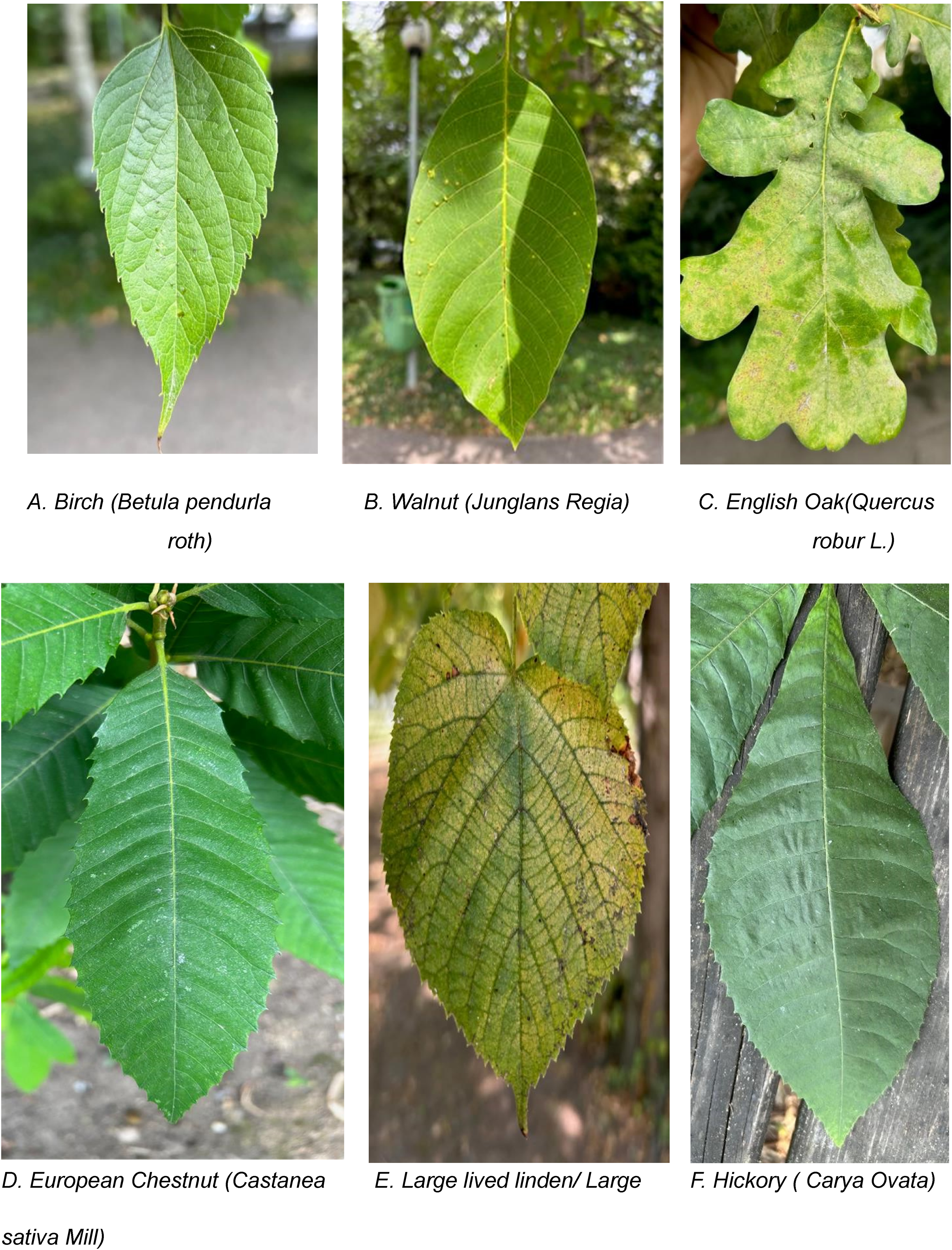
Selected leaves of the Fagales order of the study. (a) Birch (Betula pendurla roth), (b) Walnut (Junglans Regia), (c) English Oak(Quercus robur L.), (d) European Chestnut (Castanea sativa Mill), (e) Large lived linden/ Large, (f) Hickory (Carya Ovata).
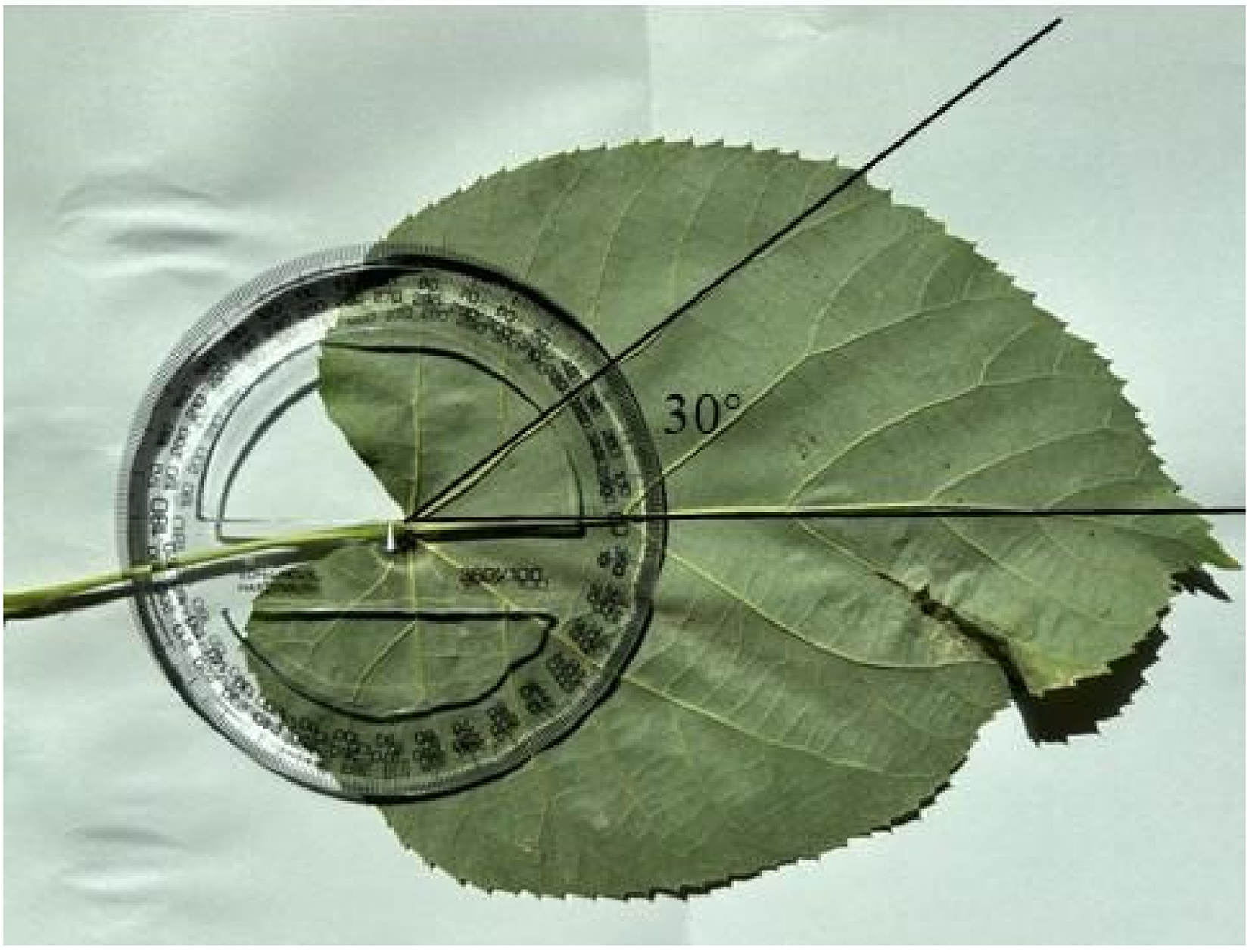
Collection of angles.
Temperature cure cycle.
In order to achieve a suitable stacking configuration, the angles obtained from the orientation of the vein were approximated to representative angles. The veins measured anti-clockwise about the mid-rib were counted/considered as positive angles and the clockwise direction was taken as negative angles. The angles were presented in Table 1.
Selection of angles.
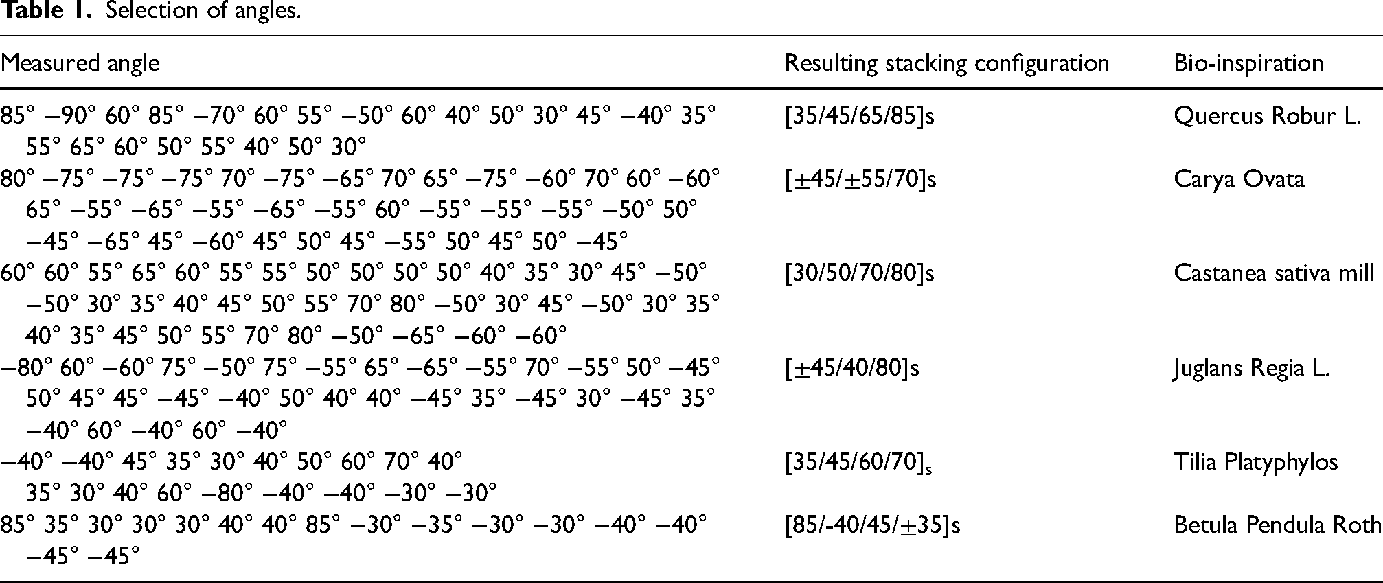
Based on the measured angles that were enumerated in Table 1, the resulting stacking configurations will be used in this study and then compared with the conventional stacking configuration already used in the industry.
Materials
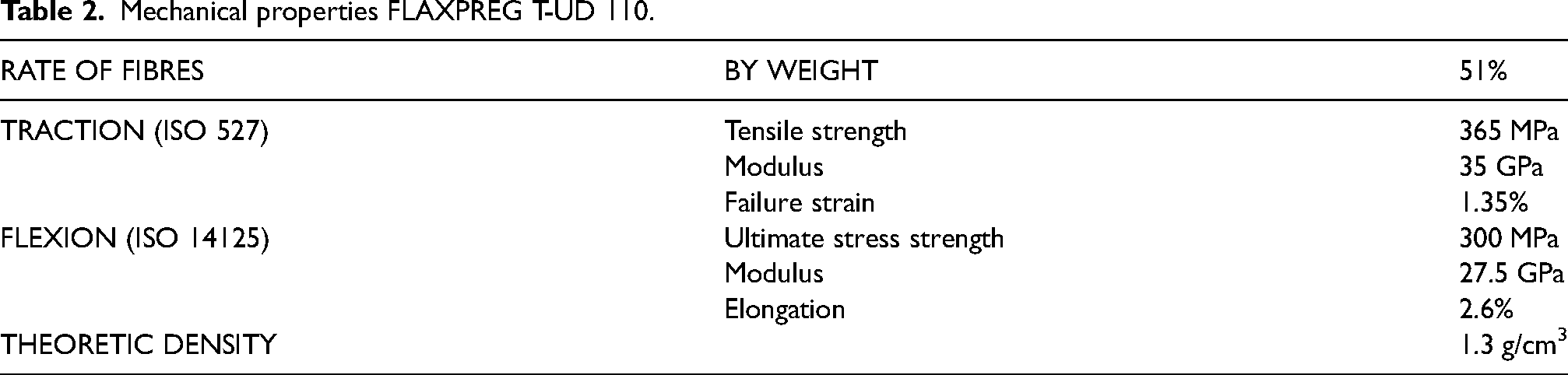
Unidirectional pre-preg flax fibre rolls, FLAXPREG T-UD 110, from Easy Composites Ltd has been used in manufacturing the samples. Table 2 details the properties of constituting pre-preg, found on a 12-ply composite, as provided by the manufacturer. 36
Mechanical properties FLAXPREG T-UD 110.
A lay-up process was implemented considering consistent with the industry standards as per ASM handbook. 37 The “parent” laminate was built to size and thickness and cut into 2 distinct samples of 100 × 150 mm using an electric guillotine. Each test sample was built into thickness of 2.4 mm and 3 mm for 8 plies and 10 plies laminate respectively. The laminate was consolidated under vacuum for 30 min every 3 plies to avoid air entrapment. For polymerisation, the laminates were placed for support on an aluminium plate and covered in release film, breather cloth as per Figure 4 while sealant and bagging material were used for creating an air-free space.
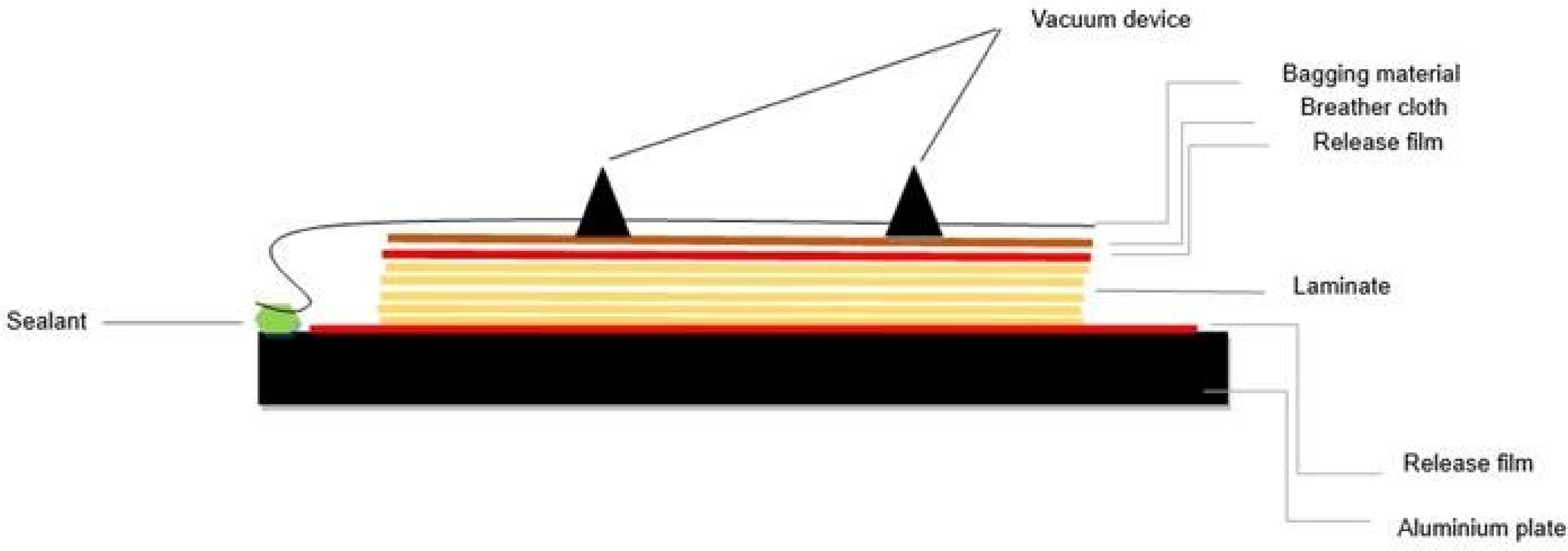
Bagging arrangement of the laminates during curing.
The samples were placed to a measured pressure of −0.85bars.
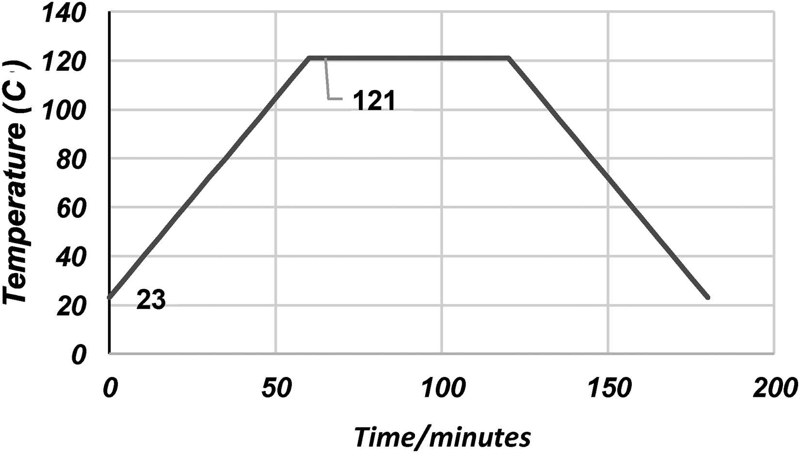
The samples were cured at a rate 1.63°C per minute, within a Didion autoclave, ASME certified
Testing
Quasi static loading test is useful in assessing the flexural strength under bending load and damage tolerance of the reinforced plastics. Quasi static loading was conducted using Tilnus Olsen universal machine 25ST as shown in Figure 5. The sample was sandwiched between two metallic plates held into position by 3 equidistant clamps to ensure that the edges were in fixed in alignment. The tipped flat ended indenter was rigidly fixed to the moving crosshead, the displacement being perpendicular to the sample. The indenter was in contact with the sample before the start of applying the load. The speed of the indenter was set to quasi-static regime of loading of 2 mm/min. For each configuration, 2 samples were tested and then averaged. Standard deviation was calculated for every averaged results. As a natural fibre, it inherently shows mechanical variability in comparison to synthetic fibres, therefore at least 2 samples are necessary for each configuration. Some possible reasons for this variability include growing and farming practices as well as mechanical extraction. 2
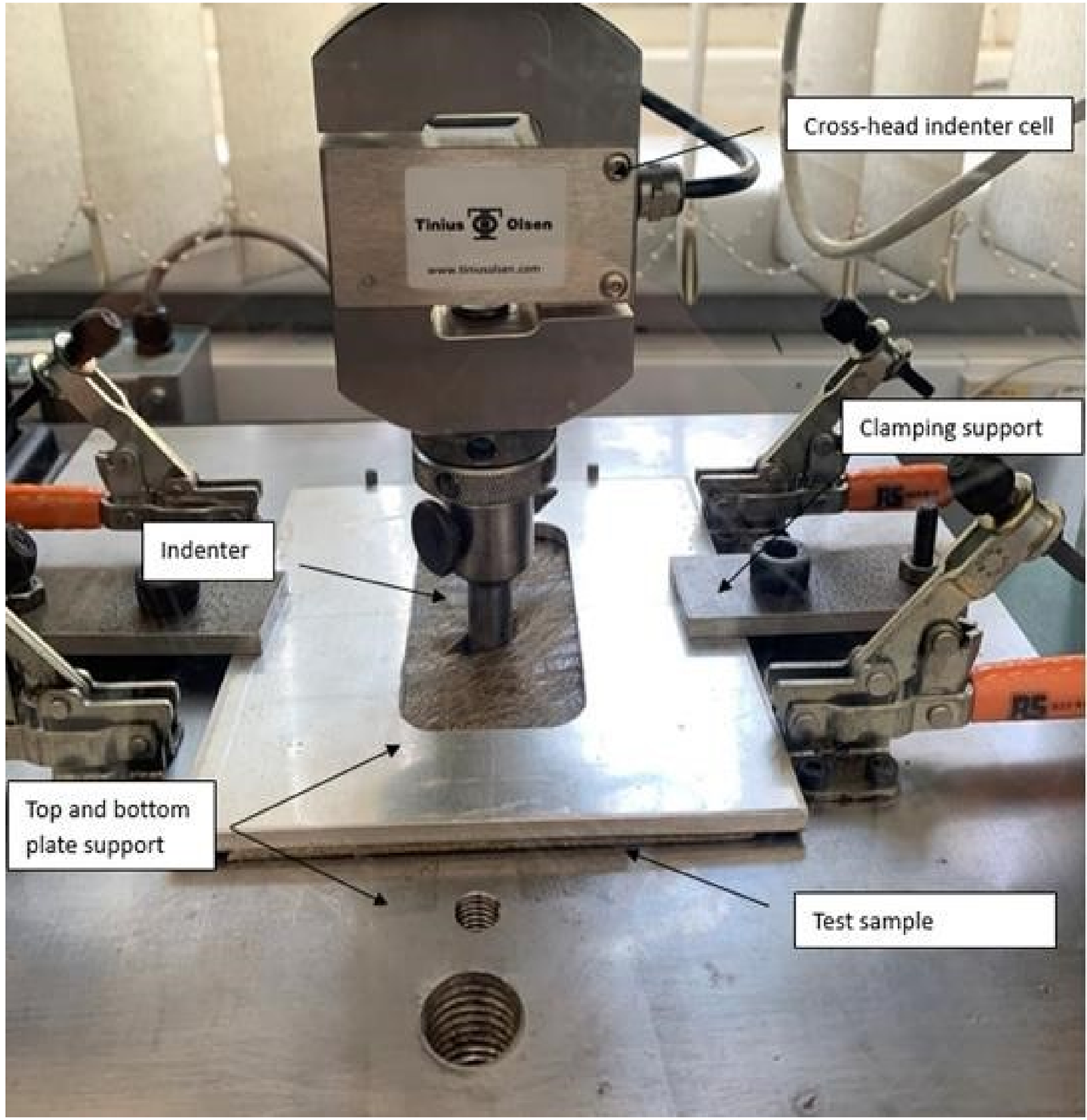
Testing set up.
Results and discussion
Figure 6 illustrates the superimposed result processing from load-displament curves of the 8-ply and 10-ply laminates for each stacking configuration. Loading of the samples going through 3 distinct phases of elastic behaviour. First stage is characteristic of elastic behaviour and a direct proportionality between load and displacement until first load drops. Small load drops can be observed in the first stage of the loading, and they are usually associated with internal matrix cracking and delamination onset as demonstrated in the study of Liang et al. 38 Natural fibres outline when subjected to loading improved kinetic energy absorption capabilities or pseudo ductile behaviour in which case, the failure is not sudden. 39
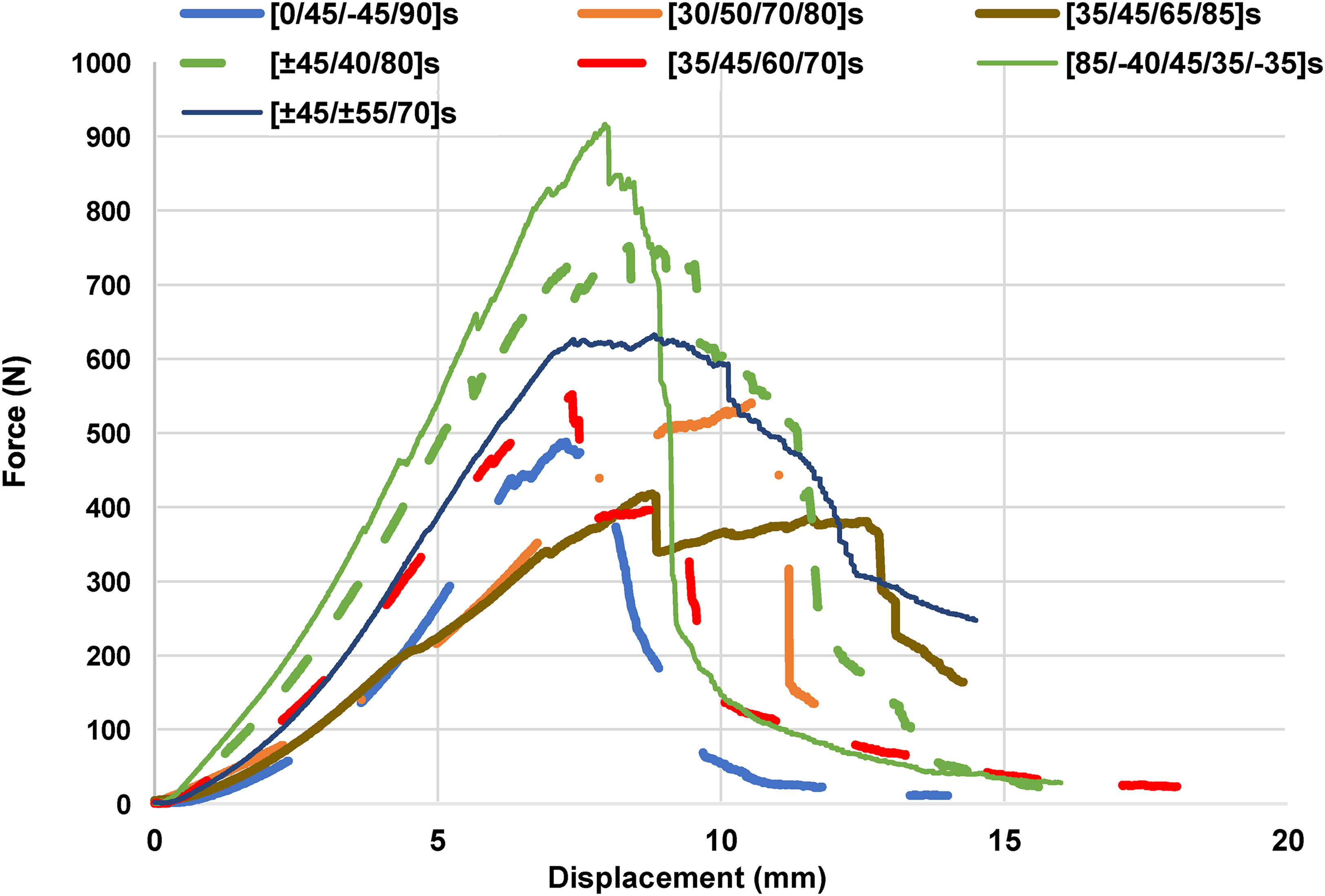
Load-displacement.
An intermediate stage usually starts between first load drop (FLD) and maximum displacement, and is characteristic to almost all researched samples except [85/-40/45/35/-35]s where the elastic capacity is almost completely lost after Dmax, the displacement corresponding to the maximum load and marks the transition between stage 2 and 3.
The 2nd stage is specific to natural fibre composites due to their inherent property such as great ductility in comparison to petroleum fibres where the failure is sudden due to their known brittleness. An exponential decrease in load carrying capacity is characteristic to all test samples in the last stage which starts after the load at maximum displacement, Ldmax, marks the transition between stage 2 and 3.
For a fair comparison between samples of different thickness, the data was normalised. In Figure 7 normalised key data and the standard deviation is illustrated regarding the maximum force and load at maximum displacement which are an indication of the load that a structure can carry safely while load at maximum displacement indicates the point where complete loss of possible. The higher the difference between Ldmax and Lp, the maximum force recorded during the testing of each sample, gives a good indication of the pseudo-ductility of natural fibre composites for mitigating any possible sudden failure. Equally, it indicates the damage resistance of the samples. On average, the difference between the 2 mentioned is 6.3% with the bio-inspired stacking configuration, [±45/±55/70]s, having the lowest difference between Ldmax, and Lp while conventional stacking configuration, [0/45/−45/90]s, having the least pronounced brittle character 15% difference between load at maximum displacement and peak load.
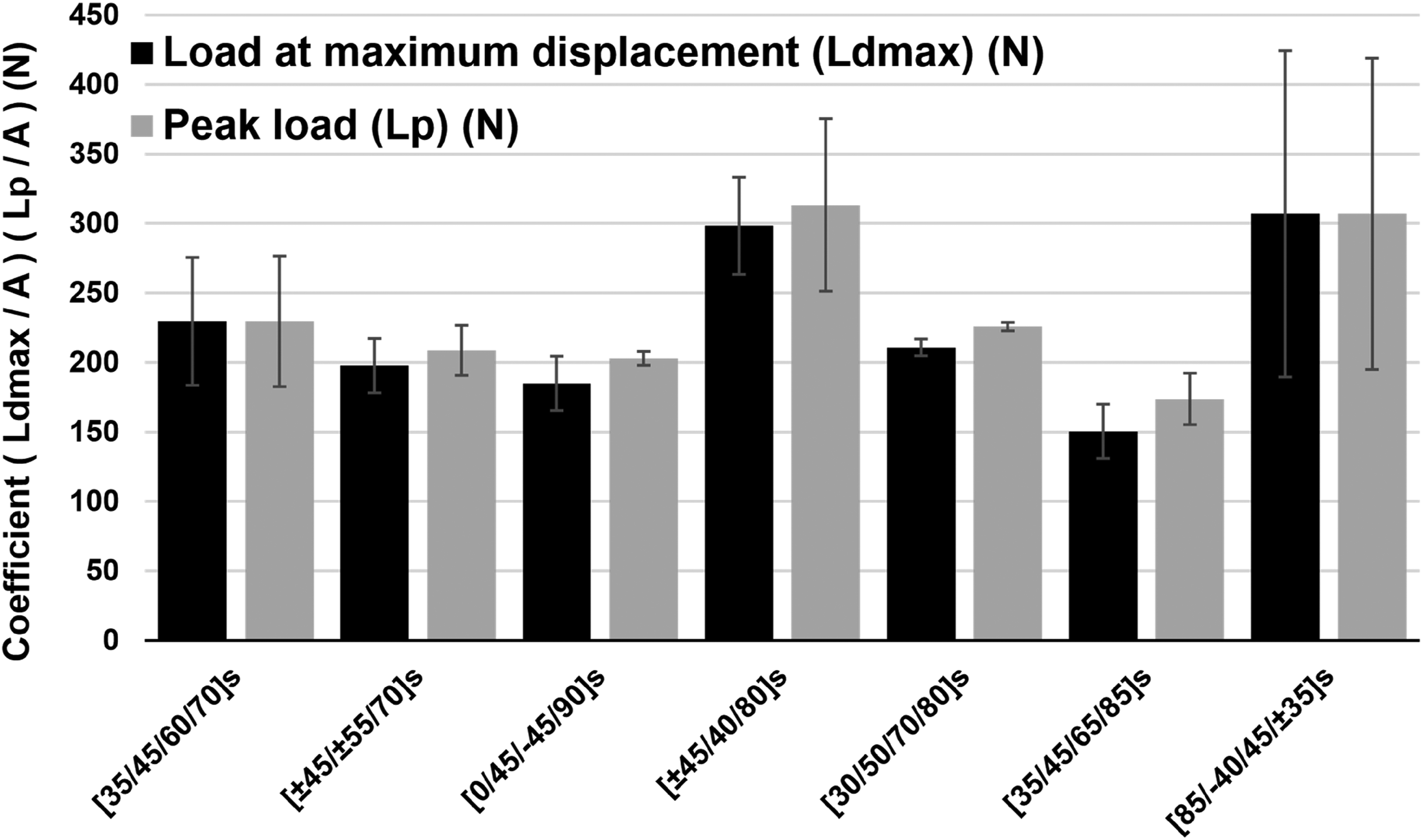
Comparison between normalised results load at maximum displacement and peak load (N).
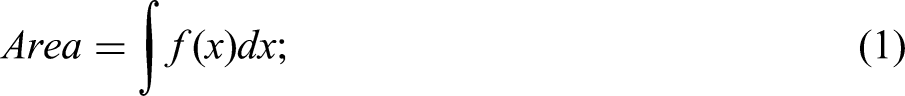
The highest peak load has been found in the walnut-inspired configuration [±45/40/80]s. while quasi isotropic, conventional had the lowest peak load a difference of 66%. The highest force at maximum displacement was found in [85/−40/45/35/±35]s while the smallest was found in quasi isotropic, conventional, [0/45/−45/90]s. Figure 8 normalised displacement and standard deviations across all samples of the indenter are showed. Significantly, the bio-inspired configuration, [30/50/70/80]s, had best displacement-behaviour for both at peak and maximum displacement while birch stacking configuration had values 60% lower than sweet chestnut. Figure 9 shows the total energy absorbed through the testing as well as the results’ standard deviation. It can be noted that the test sample with the configuration [±45/40/80]s had the highest absorbed energy value across all tested samples and 240% greater than the quasi-isotropic, conventional stacking configuration which also had the lowest energy absorption capacity. The total energy by the laminates under loading is calculated as area under the load-displacement curve represented by the formula in equation (1).
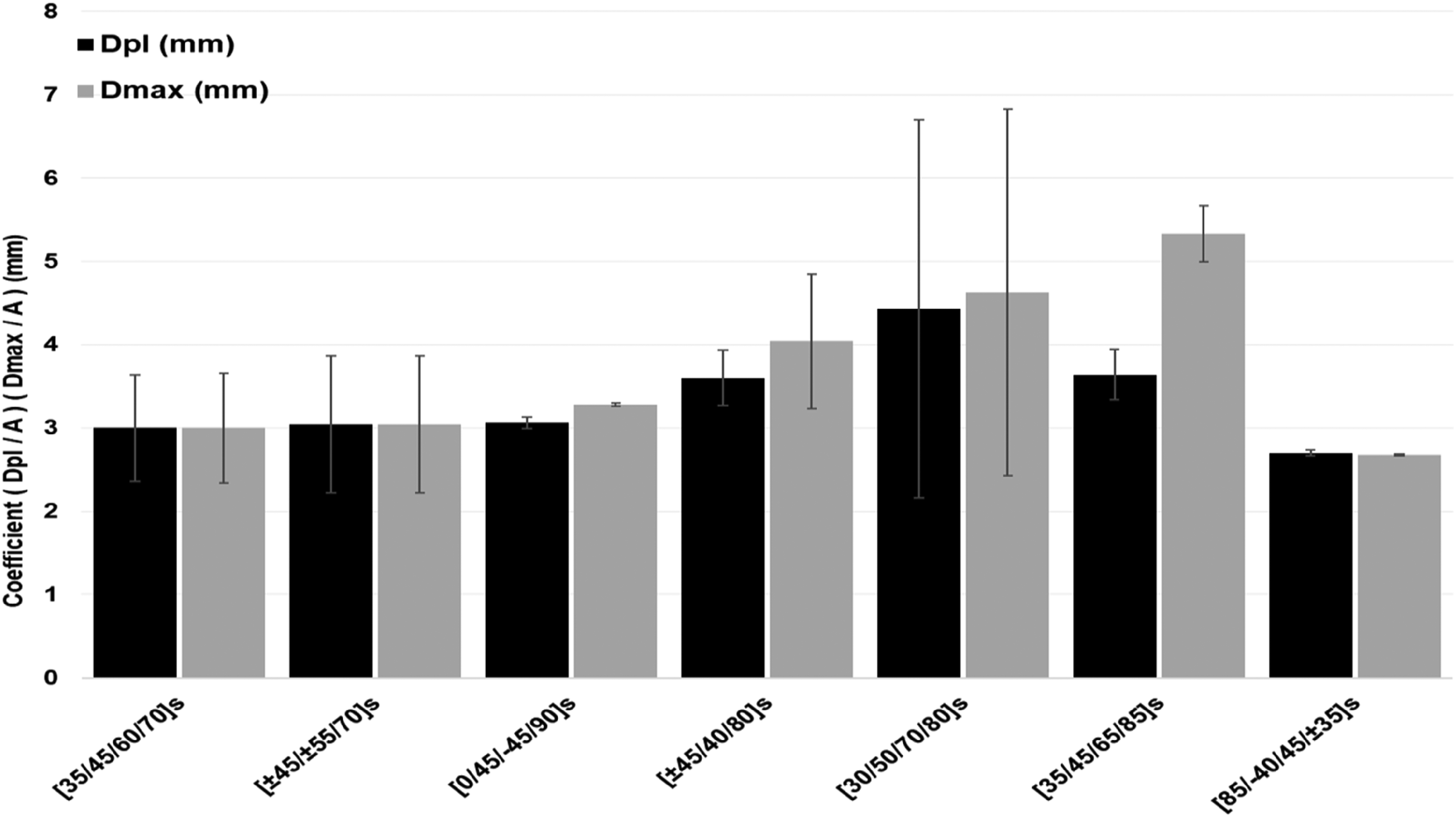
Comparison between normalised results Resulting displacement of the indenter at peak load and maximum displacement (mm).
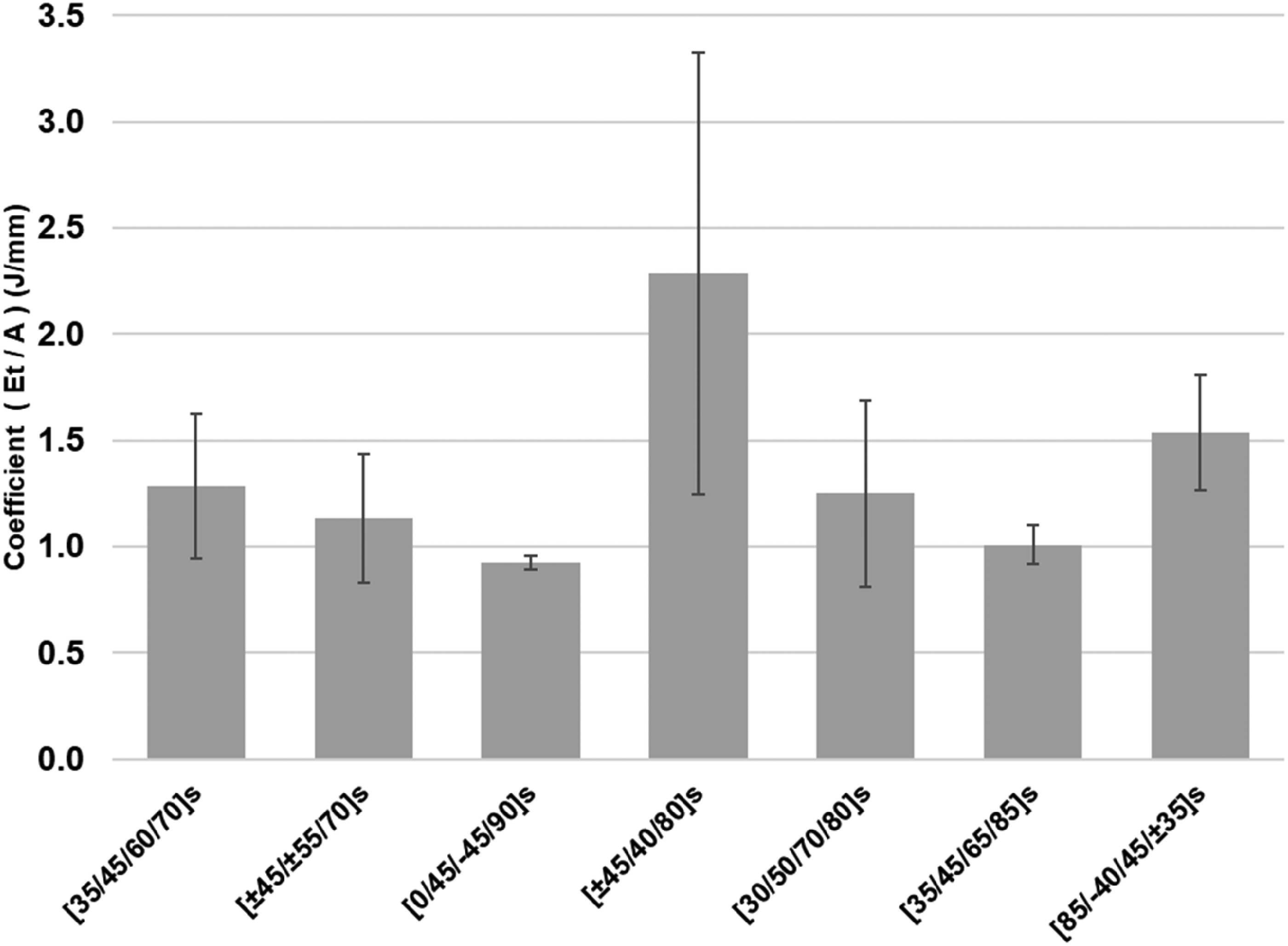
Normalised results – total energy absorbed (ET) (J).
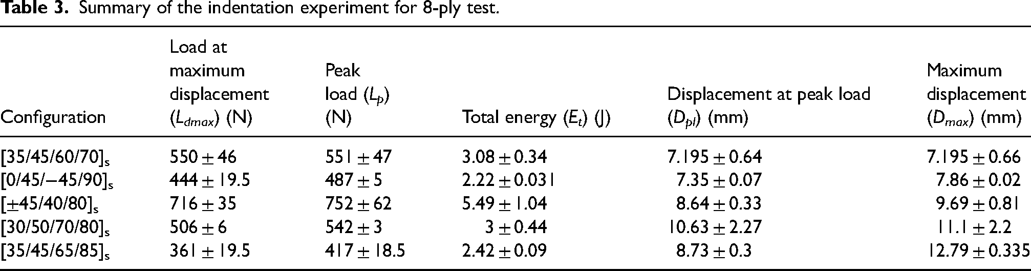
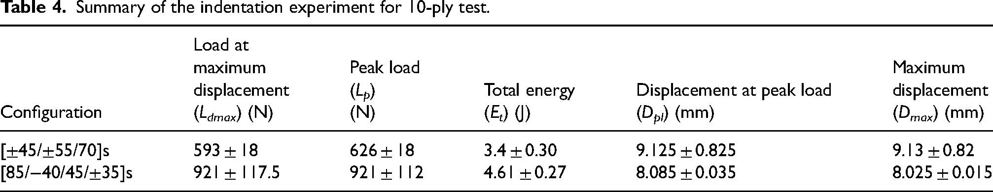
Tables 3 and 4 present the results regarding the load at maximum displacement, peak load, total energy absorbed, displacement at peak load and maximum displacement for 8-ply configurations and 10-ply configurations.
Summary of the indentation experiment for 8-ply test.
Summary of the indentation experiment for 10-ply test.
Qualitative characterization complementing numerical analysis is carried out to characterize the damage on front and back face of the samples.
Visible damage assessment
Damage can be described as physical discontinuity within the laminate matrix, resulting either from manufacturing defects, intended damage introduction or failure through cracking. 40 Quasi static loading, solely, induces two types of damage: namely barely visible damage and the surface visible damage. Macroscopic observations were made on the front and the rear surface of the tested samples in Figure 10 to observe the surface visible damage.
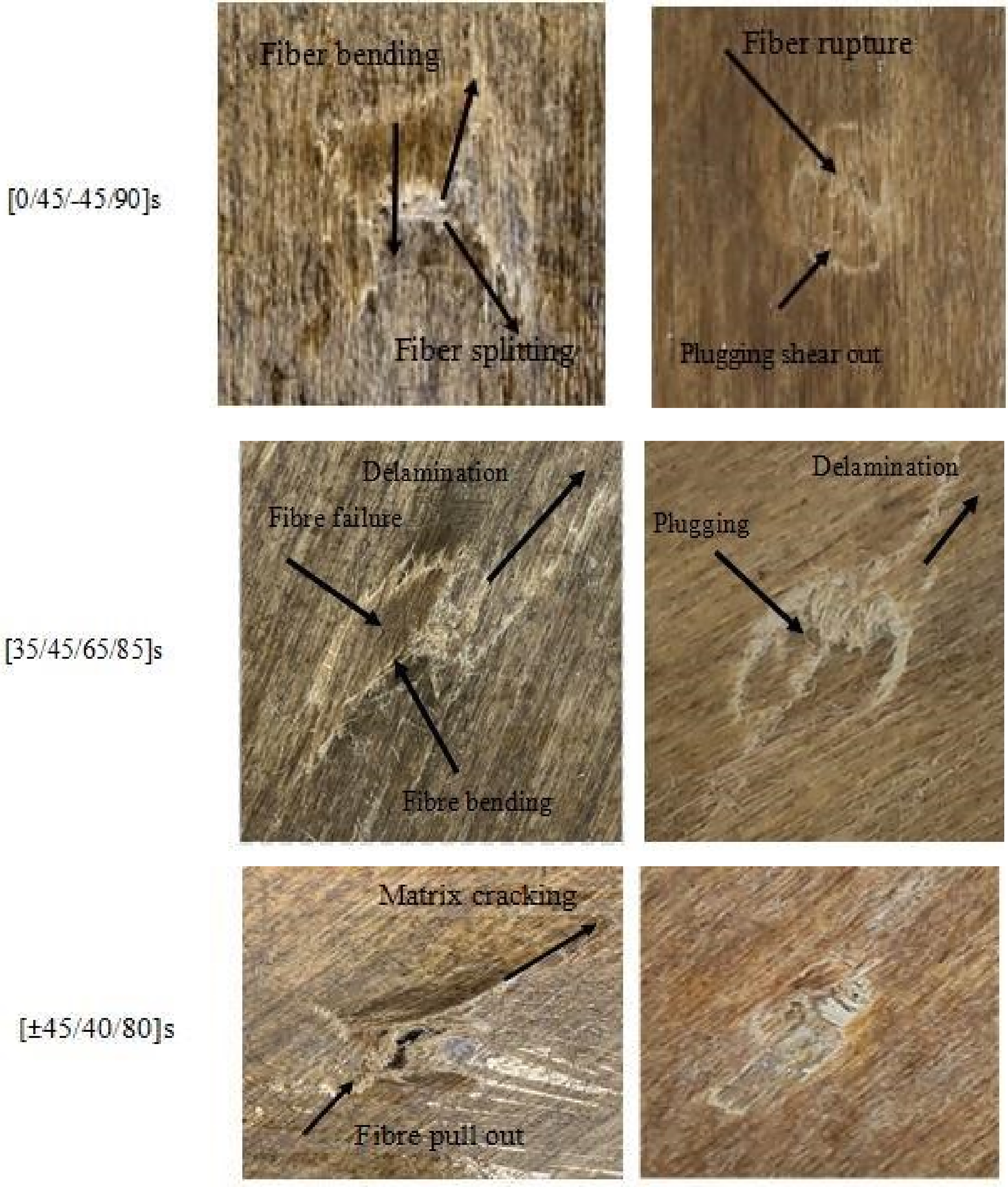
Visible damage assessment.
On the sample front side, a plastic indentation resulted from the contact with the testing indenter; while on the rear, a tail was formed due to the plastic deformation of the sample. In general, it can be stated that stacking sequence can influence the geometry of the tail and its overall direction. The tail is characterised by a diamond shape in the case of the quasi-isotropic test sample. The resulting indent from [±45/40/80]s, [±45/±55/70]s, [35/45/60/70]s which are usually oriented at 45°, was of an elliptical shape. The mis-match in bending stiffness is because of the differences in the orientation of the plies within the laminate and has effect on the resistance to the bending load. These can be compared by examination of the peak loads which are 752N, 628N and 551N respectively. The result shows that the [±45/40/80]s, and [±45/±55/70]s laminates revealed approximately the deformation 9 mm under the loading while the [35/45/60/70]s deformed by 7 mm. Hence the [±45/40/80]s is most tolerant to the deformation under static loading of the composites containing laminas of 45°.
Matrix cracking is one of the damages induced during quasi static loading and is produced due to high shear stresses. 41 It is usually associated with first load drop (FLD) and is the first damage failure to appear in laminated composites. 40
Delamination, created due to the shear stress between two neighbouring layers, is a critical damage as it decreases the strength and stiffness of the reinforced fibre structures can be observed on the front and back face of samples.40,41 Usually associated with the second stage of loading, delamination increases after the first load drop (FLD). Delamination and resulting cracks can also be identified on the rear face of [±45/40/80]s and [85/−40/45/±35]s oriented at an angle of 45°, delamination onset occurring at 550 ± 5N and 480 ± 5N respectively and similar behaviour was also found in Djilani et al. 42 Comparing the quasi-isotropic sample with the bio-inspired sample, it can be noted that the induced damage is more localised in the case of the quasi-isotropic sample whereas the failure of bio-inspired samples is more global. Transverse cracks at 45° are recurrent due to the highly anisotropic character of the bio-inspired laminates.
Fibre failure is resulting due to the loss of the matrix, being an indication of the final failure. It usually appears during the 3rd stage of the loading and is illustrated by a sudden load drop. Fibre failure is also accompanied by fibre pull out, 43 event occurring after fibre fracture and is seen as the fibre leaves the matrix “socket”. Widespread flax fibre breakage can be observed across all tested laminas in Figure 10. As it could be observed in the Figure 8, fibre failure appeared at a minimum 626N associated with the 10 ply thickness lamina, [±45/±55/70]s. Fibre failure associated with 8 ply laminas occurred after the load exceeded at least 511 ± 5N for [0/45/-45/90]s conventional ply stacking. Maximum resistance to failure was shown by [±45/40/80]s, fibre failure occurring at 768 ± 62N.
Conclusion
In this work, flax fibre reinforced composite with bio-inspired stacking configuration were tested under quasi-static loading with provision of some characterisation results. An emphasis was placed on the resulting behaviour due to the Fagalean inspired laminate arrangements. The stacking effects were evaluated by constant loading regime. The following can be picked up from the research:
Flax reinforced epoxy exhibited 3 loading stages, regardless of the lamina configuration, as a result of the quasi-static testing. A linear trend until first load drop which is usually associated with matrix cracking. An intermediate area is identified as of the force/displacement graph which is due to the fibre rupture, delamination and penetration formation mainly due to the loss of stiffness as a result the matrix mechanical properties loss. 3rd stage is characterised by total loss of stiffness, friction of the indenter with the sample and full perforation of the sample. The highest peak load has been found in the walnut-inspired configuration, [±45/40/80]s, and with 62% higher than the quasi-isotropic, traditional stacking configuration. European chestnut inspired, [30/50/70/80]s, had best displacement-behaviour for both at peak and maximum displacement with 70% higher than the quasi isotropic stacking configuration. Normalised energy absorption results were compared. It was revealed that [±45/40/80]s had the highest energy absorption capacity while quasi isotropic stacking configuration showing the lowest energy absorption capacity from all samples. The synergistic effect of cross ply angles, ±45° in the laminas are proved to be an important factor in increasing the damage resistance to quasi static loading. 0° ply is one of the factors that contributes to the reduced cross-sectional flexural strength of the quasi isotropic laminate. The damage assessment was done by observing the front and the back of the samples. It was revealed that matrix cracking, delamination, fibre failure were the principal modes of energy dissipation. All samples The visible damage, incurred by the bio-inspired, namely bending crack delamination was more general than for the quasi-isotropic sample. It was concluded that fibre orientation is the most important factor influencing failure load when compared to thickness of laminate. This hypothesis can be confirmed by the results obtained in the case of [±45/±55/70]s, 10 ply laminate and [±45/40/80]s, 8 ply laminate with a peak load of 628 and 752N respectively, outlining the importance of stacking sequence above the thickness. Despite different stacking configuration, the stacking configuration did not seem to influence the failure mechanisms, matrix cracking during the monotonic increase in load, delamination onset and fibre failure.
Overall, the bio-inspired stacking configuration hold promising potential to improve the response under compression and damage tolerance. Challenges might arise for composites with plies that are off axis (0°, 90°), predominat in bio-inspired samples. Fibres can shift or wrinkle if not properly managed and tend to misalign which can affect mechanical properties. This can be managed by using guides, marking system, or automated fibre placement to maintain consistent orientation.
Glossary
Load at maximum displacement - Ldmax – the load corresponding to the maximum displacement and marks the transition between stage 2 and 3.
Peak load - Lp – the maximum force recorded during the testing of each sample.
Dpl – displacement at peak load
Total energy – amount of energy absorbed/ involved in the testing. It is calculated using the trapezoidal rule from trapezoids built with measurement points.
Dmax – the displacement corresponding to the maximum load and marks the transition between stage 2 and 3.
First load drop -FLD- is the first significant load drop and mark the transition between stages 1 and 2
Footnotes
Acknowledgements
The authors are grateful for the University of Hertfordshire support given to this study.
Declaration of conflicting interests
The authors declared no potential conflicts of interest with respect to the research, authorship, and/or publication of this article.
Funding
The authors disclosed receipt of the following financial support for the research, authorship, and/or publication of this article: This work was supported by the University of Hertfordshire,