
Abstract
Herein, the influence of fluctuating thermal conditions on the corrosion behaviour of 17-4PH stainless steel alloys manufactured via fused filament fabrication is reported. The printed samples were sintered and then exposed to different temperature-fluctuating conditions to simulate the application environment of such alloys. The first set of samples (A) was studied as-sintered, the second set of samples (B) was aged at 480°C for 3 h followed by quenching in water, the third set (C) was exposed to conditions of B followed by aging at 360°C for 3 h and quenching in water and the final set of samples (D) was exposed to conditions of C followed by aging at 200°C for 3 h, quenching in water, aging at 400°C for 3 h, and finally quenching in water. The surface roughness evolved with the temperature conditions. The optical microscopy revealed that sample B had a fine and homogenous distribution of precipitates. Sample B had the highest microhardness values followed by C, D, and A in that order. XRD analysis revealed the presence of retained FCC austenitic phases within the microstructure whose peaks became stronger with the increased thermal fluctuations. The potentiodynamic polarisation studies revealed a distinct linear Tafel region on the cathodic region and a dual-slope inflection point on the anodic region of the polarisation curves. Sample D exhibited the highest corrosion rate whereas sample B revealed the lowest. As such, exposing fused filament fabricated 17-4 PH SS to fluctuating temperature conditions leads to degradation of mechanical strength and corrosion resistance.
Keywords
Introduction
Stainless steel 17-4 PH is the most preferred precipitation-hardening steel in applications involving high corrosion conditions. Some of these applications include food processing, chemical processing, oil and gas, radioactive storage, moulds, and dies.1,2 The alloy exhibits attractive corrosion resistance in operating conditions and therefore has been an interesting subject of research for high-temperature applications.3,4 Additive manufacturing has been recently investigated for the fabrication of 17-4 PH steel alloys for various applications.5,6 The most adopted additive manufacturing technique has been laser powder bed fusion; therefore, there is limited knowledge on the application of the other techniques in the fabrication of 17-4 PH stainless steels. Of interest, from the application point of view, is the relationship between the operating (fluctuating) temperatures and corrosion behaviour of the 17-4 PH stainless steel. Although significant results on the influence of aging temperatures on the properties of 17-4 PH stainless steels are available, little is known about the influence of the fluctuating temperature (within the operating and aging ranges) on the mechanical and corrosion properties, especially for additively manufactured stainless steel. 7
According to the literature, exposure of 17-4 PH stainless steel to high temperatures affects their microstructural, mechanical, corrosion, wear, and other properties. A study by Wu and Lin 7 investigated the influence of high-temperature exposure on the microstructure and mechanical properties of hot-rolled 17-4 PH steel. The study revealed the formation of Cu-rich precipitates (and hence precipitation hardening) when the material is exposed to temperatures between 200°C and 400°C (H900 aging conditions). Increasing the temperature beyond 400°C, coarsening of the precipitates occurs leading to reduced mechanical strength. Heat treatment of 17-4 PH SS produced via binder jet AM was reported by Huber, Stich, and Fischer 8 and revealed the formation of retained austenite structure and loss of hardness in H900 heat treatment. Additive manufacturing of 17-4PH stainless steel has been studied and various aspects have been investigated. Material extrusion additive manufacturing technique (or Fused Filament Fabrication, FFF), which involves the use of metal/polymer composite feedstock followed by debinding and sintering, is one of the most currently investigated. 9 Alkindi et al. 10 investigated the effect of print orientation on the mechanical properties of 17-4PH stainless steel and reported that samples prepared at 0° orientation exhibited twice the tensile strength of the 90° oriented samples. A comparative study on the properties of 17-4 PH processed via atomic AM and FFF was presented and demonstrated that the properties for each manufacturing process depended on the sintering parameters and the debinding methods. 11 A similar study compared FFF and selective laser melting (SLM) methods for the fabrication of 17-4 PH SS and demonstrated that SLM samples exhibited better hardness and wear resistance. 12 Zhang and Roch demonstrated that the elongation and yield strength of 17-4 PH SS produced via FFF increased after annealing and hardening processes. 13
As highlighted, 17-4 PH stainless steel is extensively used in the fabrication of injection moulds and therefore usually exposed to thermal fluctuations during operation. Although there is evidence of the phase transformations and mechanical evolution during heat treatment of additively manufactured 17-4 PH SS,14–16 to the best of our knowledge, there is no published work on the effect of thermal fluctuations on the properties of the alloy. In this work, for the first time, the influence of the thermal fluctuations on the corrosion behaviour of the fused filament fabricated 17-4 PH SS is reported. The 3D printed 17-4 PH SS have been exposed to various conditions of fluctuating thermal treatments (simulating injection moulding temperature conditions) and their properties were investigated.
Materials and methods
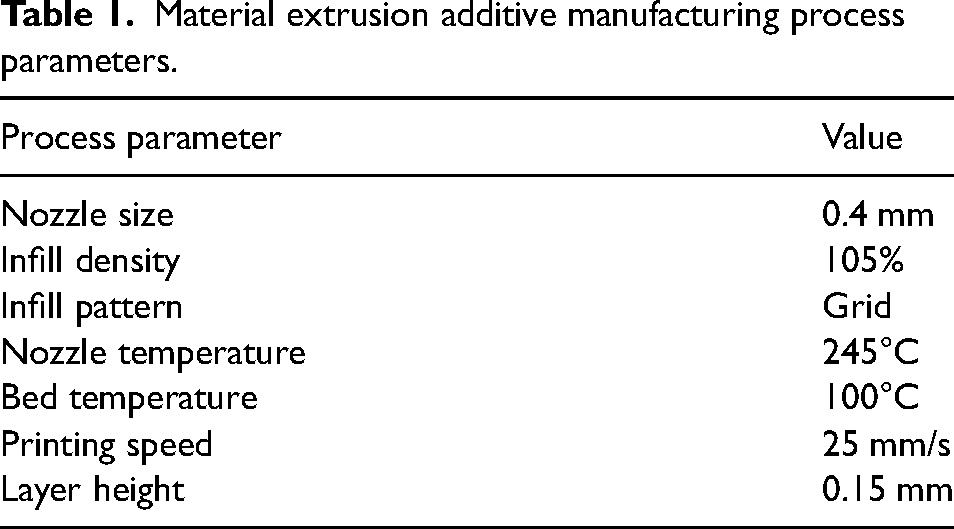
In this work, an Ultra-fuse 17-4 PH stainless steel filaments of 2.85 mm diameter (BASF 3D printing Company, Heidelberg, Germany) was used to manufacture 10 × 10 × 10 mm samples on Ultimaker S5 (Ultrecht, Netherlands) material extrusion machine. The filaments were composed of 80%wt. 17-4 PH stainless steel and 20%wt. PLA. The material extrusion additive manufacturing (MEAM) parameters of the printer are presented in Table 1.
Material extrusion additive manufacturing process parameters.
The 3D-printed (green) samples were then taken through the catalytic debinding process according to the BASF recommended procedure. The process involved exposing the green parts to gaseous nitric acid in a nitrogen atmosphere at a temperature of 120°C for 48 h to obtain PLA-free samples known as brown parts. The brown parts were then sintered in 100% clean and dry argon gas (dewpoint > −40°C) through the following cycle. At a rate of 5°/min, the samples were heated from room temperature to 600°C and held at this temperature for 1 h. Then, the samples were heated further to 1300°C at an increasing rate of 5°/min. The samples were kept at this temperature (1300°C) for 3 h. Finally, the samples were allowed to cool slowly in the furnace. Upon sintering and cooling, there was shrinkage as the metal particles combined into a solid mass (see a picture of the green and sintered parts, Figure 1). 17 The constituents of the 17-4 PH SS after sintering were Cr (15–17.5 wt.%), Ni (3–5 wt.%), Cu (3–5 wt.%), Si (≤1 wt.%), Mn (≤1 wt.%), Nb (0.15–0.45 wt.%), C (≤0.07 wt.%), and Fe (balance).
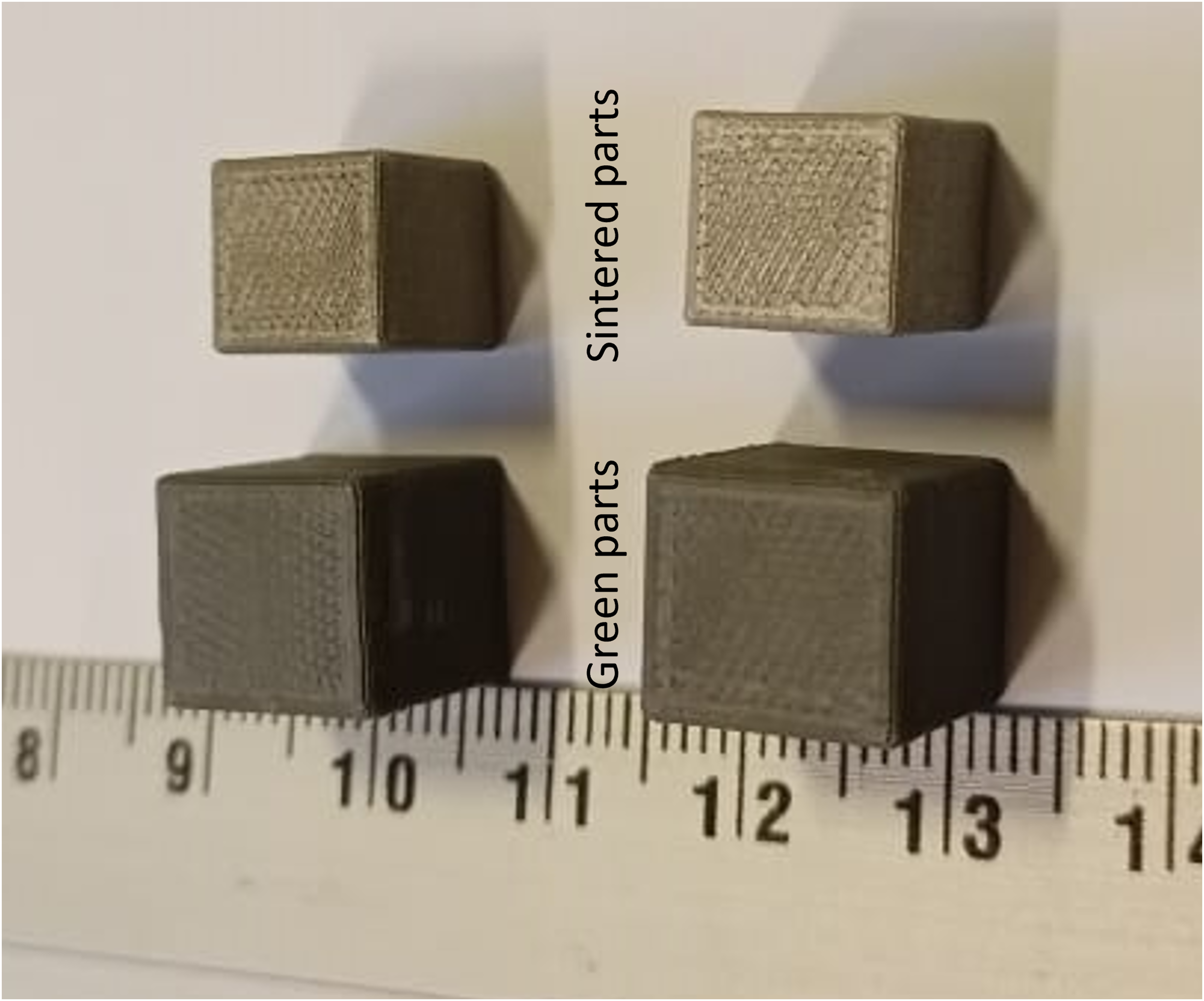
A picture of the 3D printed parts before sintering (green) and after sintering.
The sintered samples were then exposed to fluctuating temperature conditions for 3 h in an oven as detailed in Table 2. The temperature conditions were chosen based on the H900 aging process and the operating temperatures of the alloy in injection moulding applications. The alloy (17-4 PH) finds application in the fabrication of injection moulds and during the process, temperature is a very critical parameter. 5 In a typical injection moulding process, there is a variation of the temperature within the moulds between 400°C and 200°C. 18 As such, the conditions presented in Table 2 represent thermal fluctuations in a typical injection moulding process. Additionally, the choice of these fluctuating conditions is inspired by the recommended heat treatment conditions for stainless steel alloys. 5
Thermal fluctuating conditions of the FFF produced 17-4 PH stainless steels.
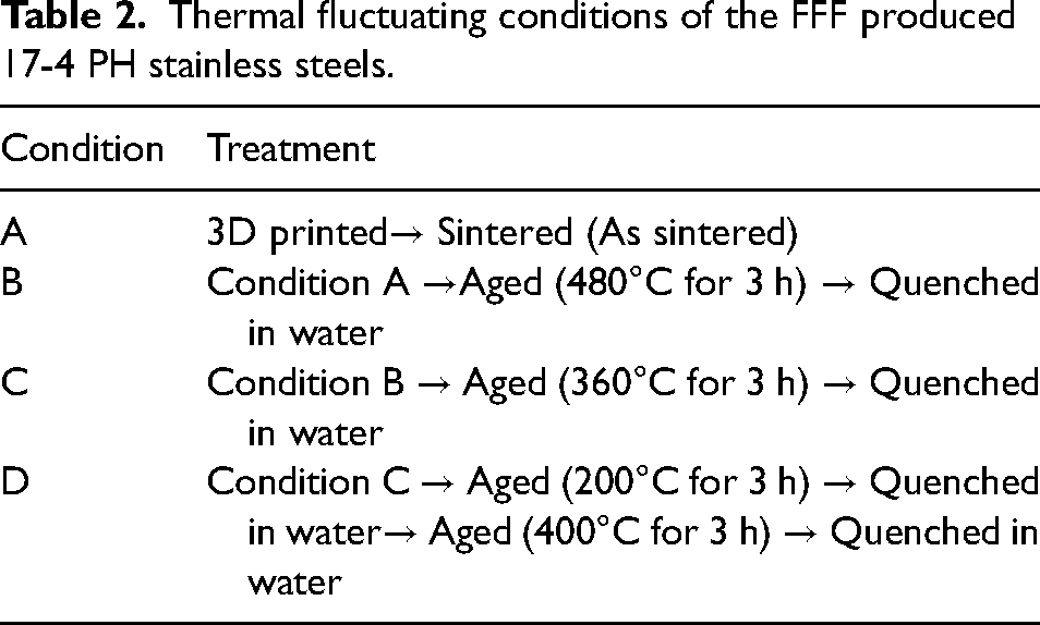
The samples exposed to conditions A, B, C, and D were then denoted as Sample A, Sample B, Sample C, and Sample D respectively and shall be referred as such throughout the rest of the article.
The topography of the 17-4 PH/PLA filament and the 3D printed samples was analysed using a Confocal Laser Scanning Microscope (CLSM) (LEXT OLS5100, Olympus, UK) using both optical and laser modes. The preparation of metallographic specimens was undertaken following the standard procedures. The samples A, B, C and D were chemically etched using Nital (a solution of 10 ml of HNO3 and 100 ml of ethanol) to reveal the microstructure and phases of the 17-4PH stainless steel. The microstructure characterisation was undertaken using an optical microscope and Zeiss Sigma field emission gun scanning electron microscope (FEG-SEM, Carl Zeiss, Germany). A Bruker D2 Phaser instrument (using monochromatic Cu-Kα radiation) was used to determine the phases and crystal structure according to ASTM E975. 19 The microhardness was undertaken on the top surfaces of all the samples using the Vicker's hardness machine at a dwell time of 15 s and a test force of 10 kgf. For each sample, six Vicker's hardness values were taken for statistical accuracy of the results. The corrosion test was carried out using the standard three-electrode system. In this system, the 17-4 PH stainless steel sample (with a cross-section area of 1 cm2), a graphite rod, and glass body calomel with Ag/AgCl 3 M KCl were used as the working, the counter, and the reference electrodes, respectively. The tests were conducted on all four samples at room temperature (25°C) inside 3.5 wt.% NaCl solution at a pH range of 6.5 to 7.2. An Autolab PGSTAT 101 Metrohm Potentiostat was used to generate the polarisation curves and the experiment was undertaken according to ASTM G5-14. 20 After the corrosion test, scanning electron microscope (SEM) and energy-dispersive x-ray spectroscopy (EDS) were undertaken on all samples to study the corrosion mechanisms.
Results and discussion
Surface topography
The surface morphology of the 17-4PH-PLA composite filaments and the top and side surfaces of the 3D-printed 17-4PH-PLA samples (before sintering) are shown in Figure 2. It can be seen the distribution of the PLA within the 17-4PH matrix filament (Figure 2(a)) does not change upon 3D printing (Figure 2(b) and 2(c)) except for the increase in surface roughness due to the stair casing effect of the fused filament fabricating (FFF) printer. The corresponding height maps are also shown from which the average (Sa) roughness values on the top and side surfaces on the printed samples were obtained as 5.94 μm (root mean square, Sq, 8.85 μm) and 15.04 μm (root mean square, Sq, 18.50 μm) respectively. To evaluate the quality of the fabricated 17-4PH stainless steel after sintering and heat treatments, topography images were also taken using confocal laser scanning microscopy on the top and side surfaces of the samples (Figure 3). Both intensity (on the lefthand of Figure 3) and height (righthand of Figure 3) maps for each sample were obtained, and these images generally show the surface roughness as well as the aesthetic appearance of the printed product. The top surfaces of Samples A, C, and D revealed valleys and deeps whereas the top surface of Sample B appeared homogenous and compact. These valleys and deeps represent 3D printing defects such as cracks and voids arising from the stair casing effect of the fused filament fabrication (FFF). 21 The staircase effect arises from the layer-by-layer deposition of the material during the fused deposition modelling process after sintering. Similar observations were reported by Opoz et al. 22 The surface roughness generally increased for all samples upon sintering (Figure 4). The as-sintered sample A (before heat treatment) revealed higher Sa and Sq values on the side surface than on the top surface. In sample B, the top surface exhibited lower Sa values than the side, whereas the Sq values were vice versa for the two surfaces. Sample D exhibited the highest values of roughness on both surfaces, which could be attributed to the evolution of surface structures due to conditions of heat treatment. Further measurements of the surface structures for samples A, B, C, and D are represented in Figure 5.
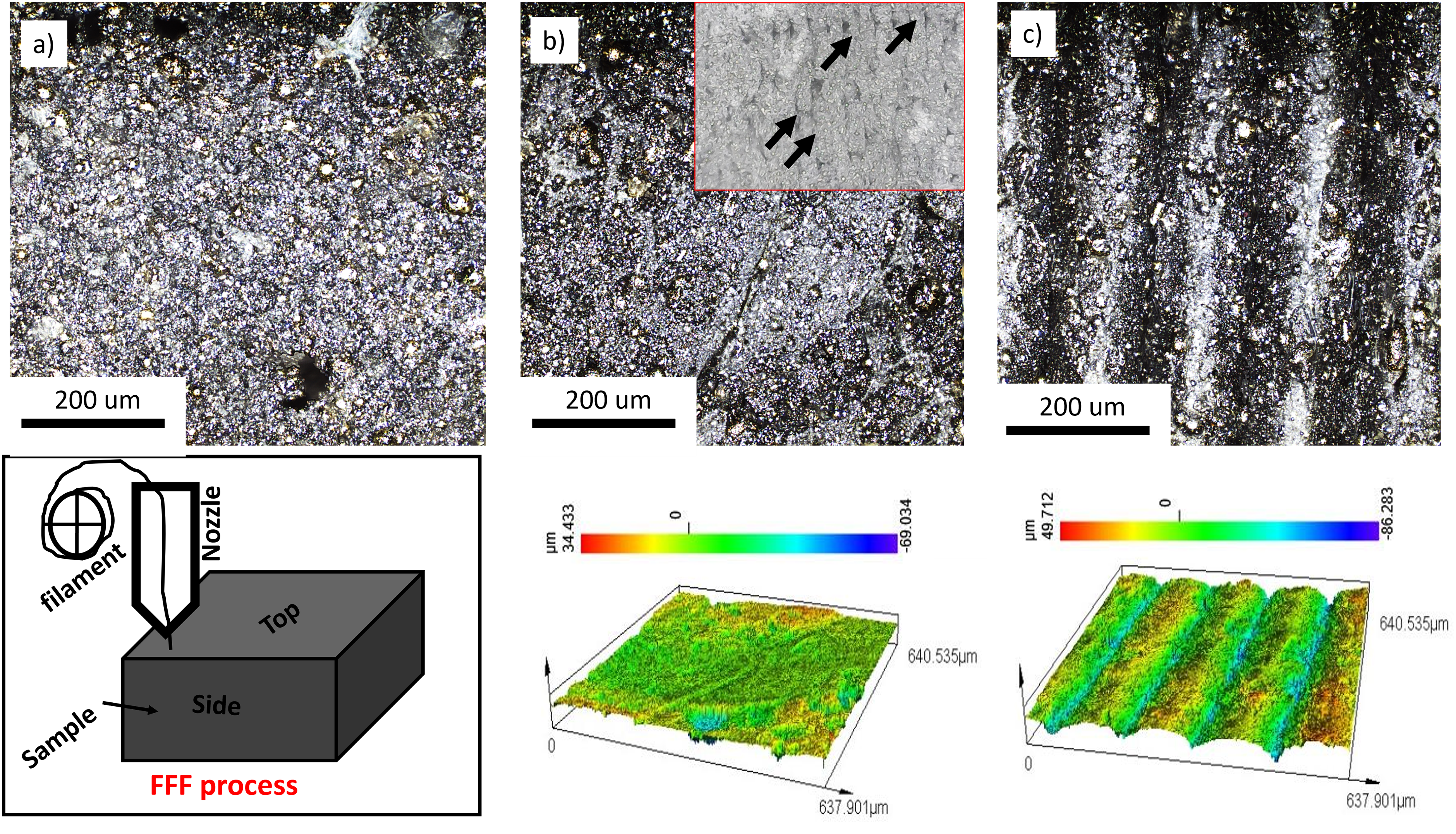
Confocal microscope images of (a) 17-4PH-PLA composite filament, (b) top surface of 3D printed 17-4PH-PLA (before sintering), and (c) Side surface of the 3D printed composites and their corresponding height maps. The inset image (lower left) is the FFF process showing the top and side surfaces of the 3D printed 17-4PH-PLA composite sample. The inset in b) is the optical image of the internal structure of the 3D printed 17-4PH/PLA composite in which the arrows demonstrate the stair casing effect and voids between the printing layers.
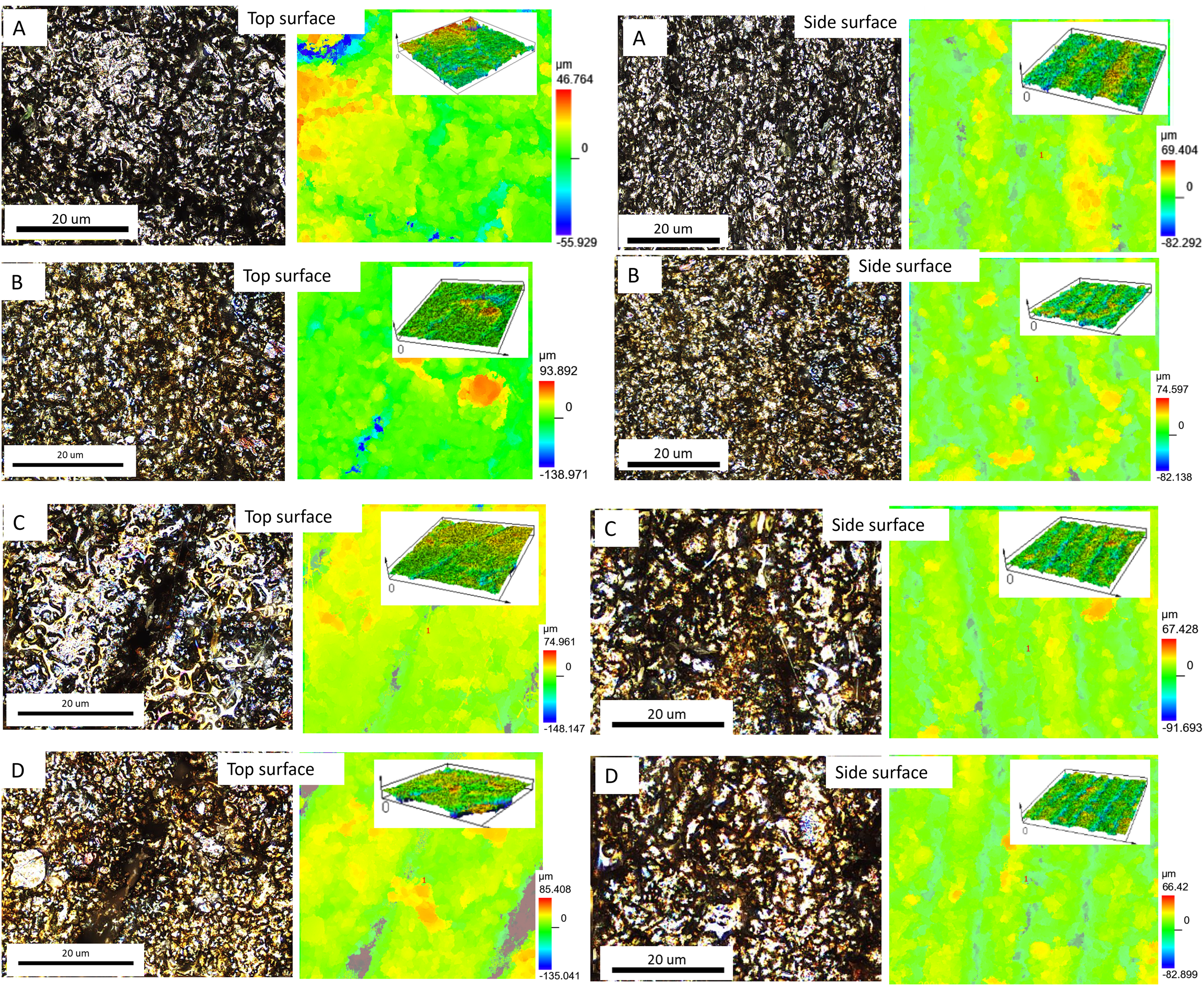
Intensity (left) and height (right) maps for topography observations of samples A, B, C, and D on top and side surfaces. The insert shows the 3D images of the height maps of the surfaces.
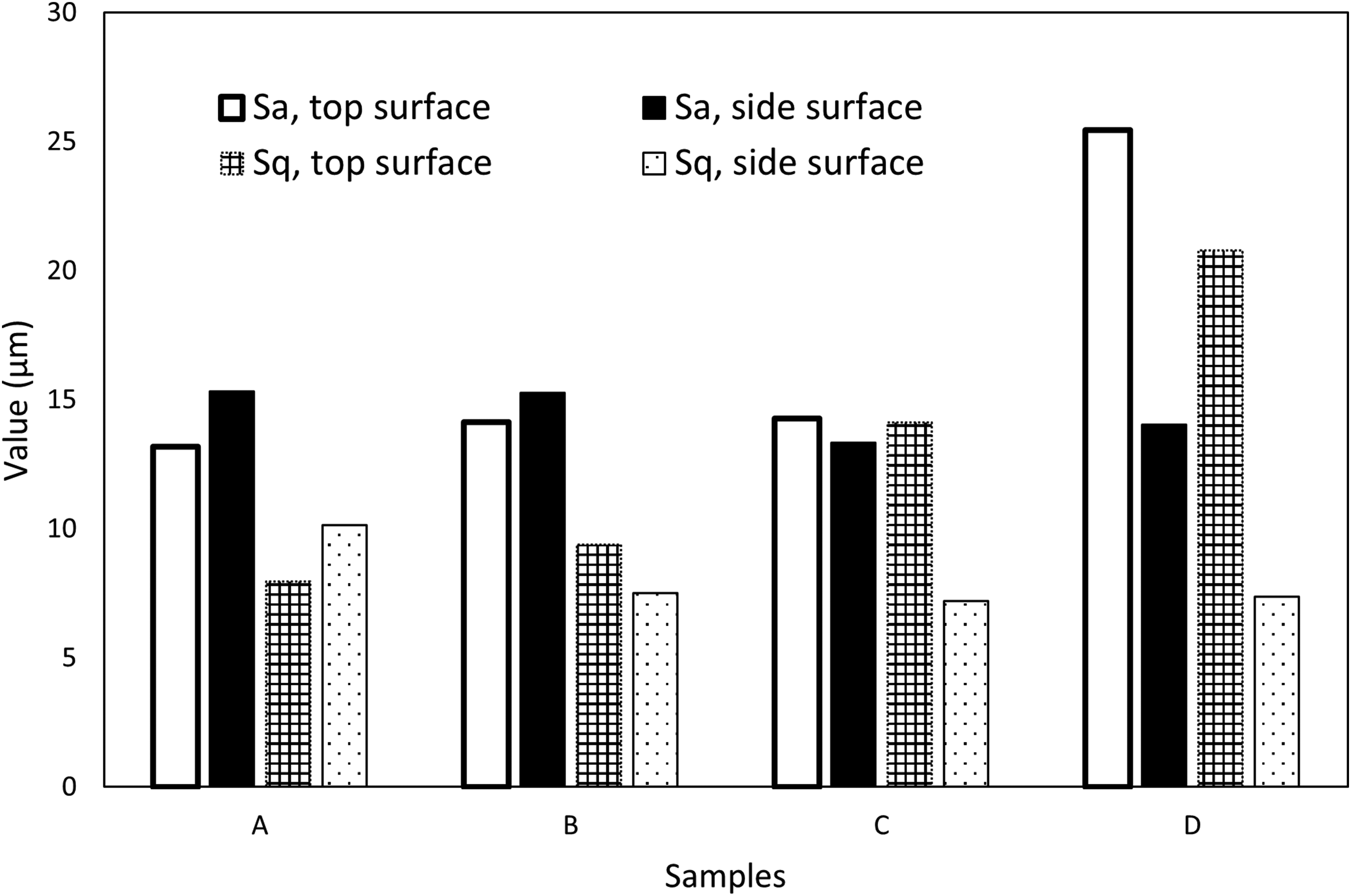
Area roughness (Sa) and root mean square roughness (Sq) values on the top and side surfaces of the 3D printed 17-4 PH samples.
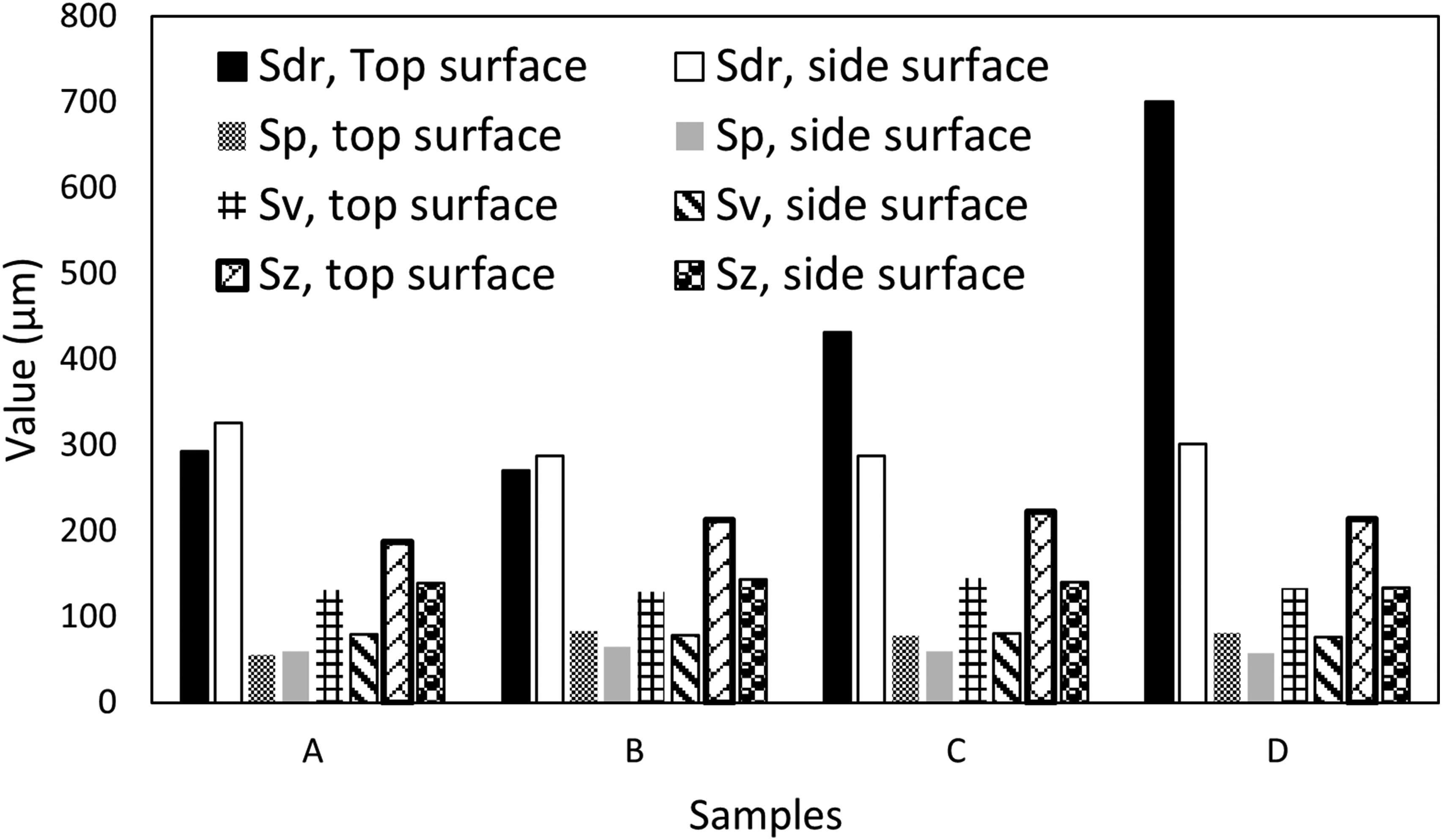
Surface roughness depth (Sdr), Maximum peak height (Sp), Maximum valley depth (Sv), and Maximum height of the surface (Sz) of the 3D printed 17-4PH stainless steel samples after sintering and different heat treatment routes.
As shown in Figure 5, surface roughness depth (Sdr), which measures the maximum depth of the surface irregularities, increased from samples A, B, C, and D, with the Sdr values of D being double that of sample A. Sample B revealed the lowest Sdr value, which can be related to reduced surface roughness and homogenous microstructure. There were no significant differences in the maximum peak height (Sp) values among all the samples. In terms of the maximum Valley Depth (Sv) values, which measure the depressions present on the surface were also nearly equal across the four samples (Figure 5). The Maximum Height of the Surface, Sz, determined as the difference between Sp and Sv values, was obtained as 139.1 μm, 143.4 μm, 140.2 μm, and 133.6 μm for samples A, B, C, and D respectively. These results indicate that the sintering and heat treatment processes do not eliminate the surface asperities; the sintering eliminates the PLA binder and removes the staircases as well as most of the voids (shown as inset in Figure 1(b)) within the internal structure of the printed part. Next, the samples were ground and polished as per the standard metallurgical procedure 23 to obtain surfaces with Sa and Sq values as 0.147 μm and 0.712 μm, respectively (Figure 6). This means that 17-4 PH stainless steel produced via FFF (sintered and heat treated) can achieve superior finish upon mechanical polishing.
The optical pictures of the surfaces of the polished 17-4PH samples after sintering, A, and after different heat treatment routes (samples B, C, and D).
Microstructure
The microstructure of the samples obtained via the optical microscopy in Figure 7 showed that upon sintering and heat treatment, the 3D printing stair casing effect and layers were no longer visible. On the sintered 3D printed 17-4PH stainless steel (sample A), there were cracks and pores on the martensitic matrix of the 17-4PH stainless steel (Figure 7(a)). On heat treatment (Aging (480°C for 3 h) and quenching in water), there was a transformation of the microstructure in which there was a formation of fine and particulate precipitates uniformly distributed within the martensitic matrix (Figure 7(b)). These precipitates are usually Cu-rich phases although they were not detected on the XRD results (Figure 8) due to the low content of such nanoparticles. Similar observations were reported by Pan et al. 24 on heat treatment (thermal aging) of 17-4PH martensitic stainless steel fabricated by direct energy deposition. Unlike sample A, there were few pores and no cracks observed in sample B. The condition B represent the precipitation hardening heat treatment of 17-4PH stainless steel although in this case it was undertaken for 3 h. 25 During this process, precipitates form within the martensite matrix, usually in the form of copper-rich phases. These precipitates contribute to the precipitation strengthening of the alloy. 8 On further exposure of the samples to condition C, there was transformation of the fine structures (observed in B) into an elongated and fine-needled microstructure (Figure 7(c)). The samples exposed to conditions D revealed agglomeration of the elongated precipitates and structures within the martensitic matrix (Figure 7(d)).
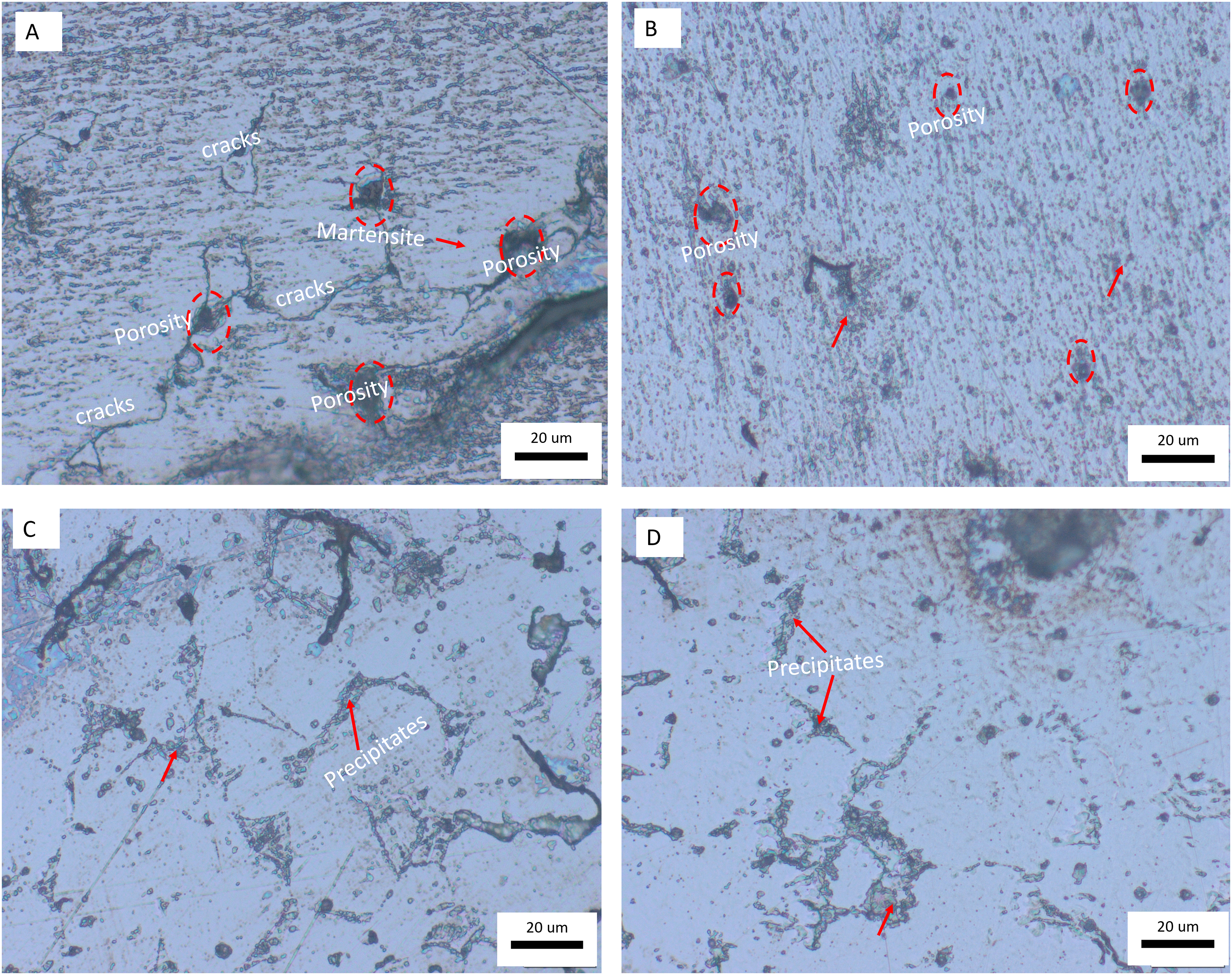
Optical micrographs of the printed 17-4PH stainless steel before and after heat treatment.
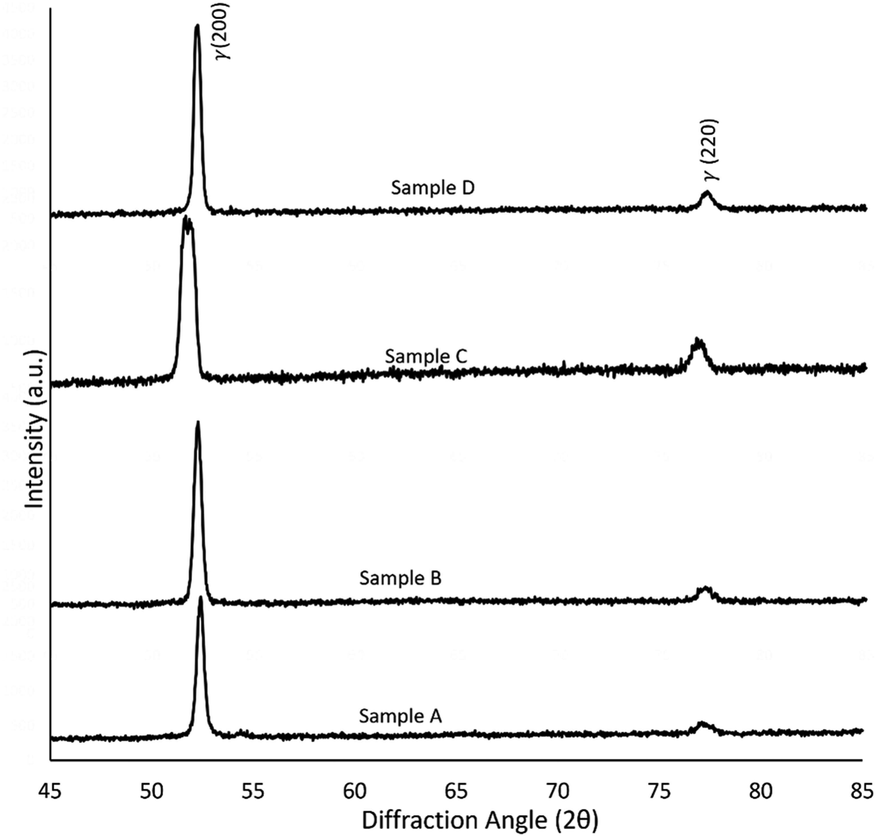
XRD patterns for the 3D printed 17-4 PH stainless steel samples exposed to fluctuating temperatures.
X-ray analysis
To determine the phases and crystallography, XRD analysis was undertaken on the four samples (Figure 8). For all samples, the XRD revealed the obvious (110) peaks depicting BCC structures (martensitic
Microhardness
The microhardness values were obtained as 260.73 ± 22.74 HV, 349.32 ± 4.60 HV, 316.76 ± 20.80 HV, and 304.51 ± 19.42 HV for samples A, B, C and D respectively (Figure 9). Sample A exhibited the lowest Vickers microhardness value, which can be related to the topographical and microstructural observations which revealed presence of cracks and porosity. The value is closer to that reported by Kovacs et al. 27 for as-sintered 17-4 PH stainless steel fabricated via laser powder bed fusion. There was an increase in microhardness in sample B, which could be attributed to the homogenous dispersion of fine precipitates within the microstructure; these precipitates contribute to strengthening through the precipitation hardening process and hence an increase in microhardness values. The conditions for sample B represent the standard thermal aging conditions of 17-4PH stainless steel under which precipitation of Cu and Nb-rich phases are reported. 28 The value of hardness obtained at condition B agrees with the ASTM A693 standard for H900 heat treatment, which dictates a Vickers hardness of about 348 (HV).29,30 The low microhardness values in samples C and D could be attributed to the presence of fine-needle structures, which act as sites for stress-raisers which lead to a low mechanical strength. The results indicate that exposure of fused filament fabricated17-4PH stainless steel to fluctuating temperature leads to a reduction in hardness.
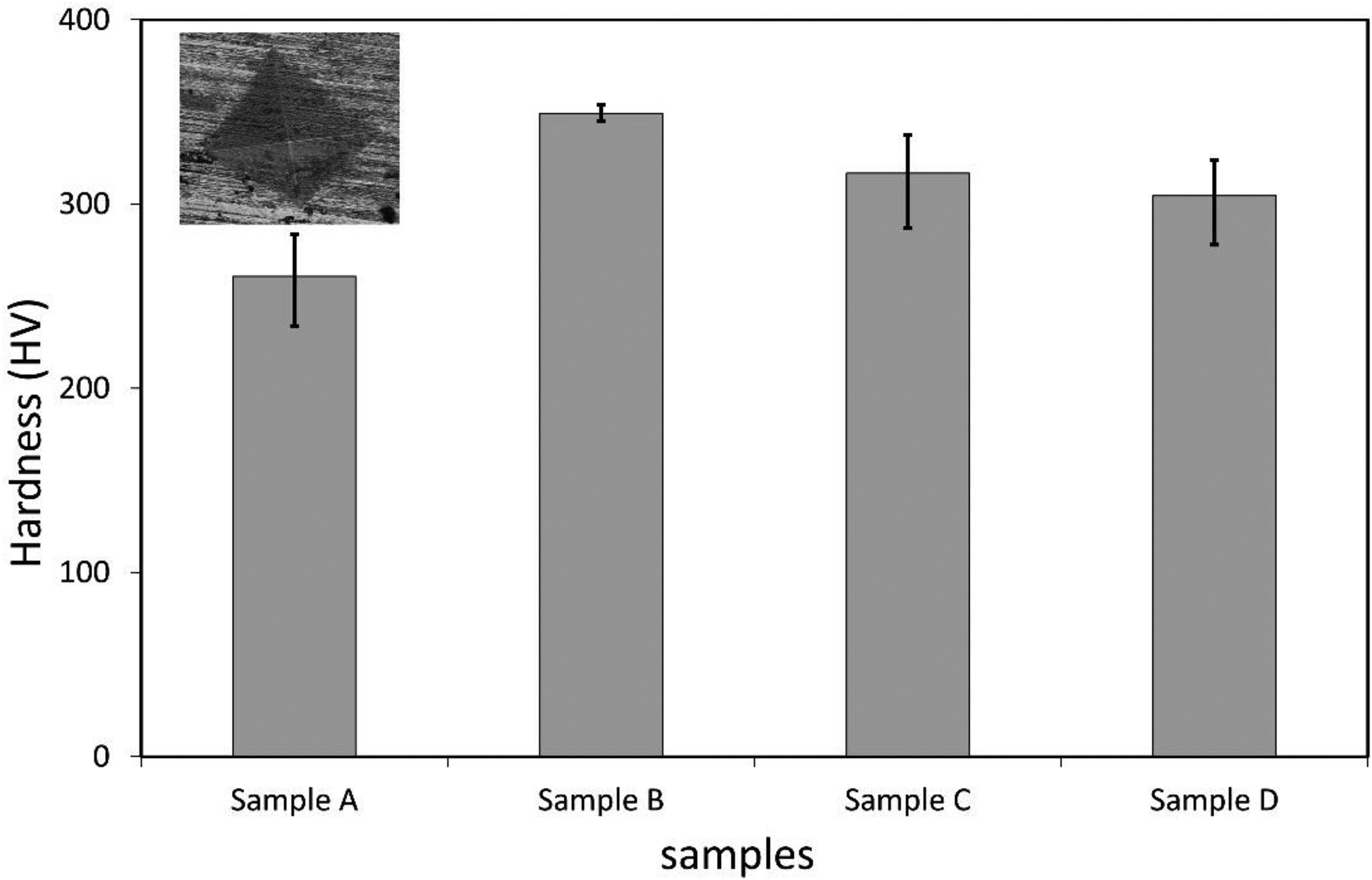
Vickers microhardness values of the 3D printed 17-4 PH stainless steel. The error bars representing the standard deviations of the average hardness values are also shown. The microhardness indentation is shown as inset and represents considerable deformation of the surface of the stainless steel.
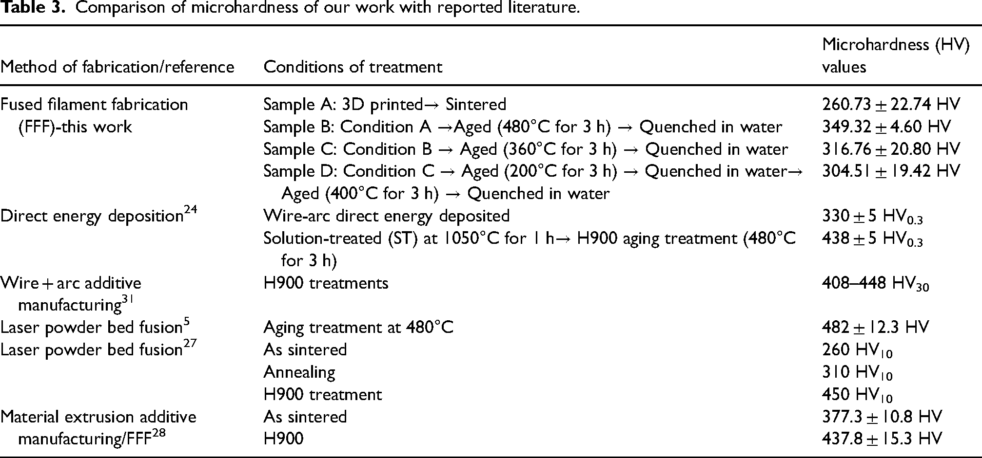
Further, a comparative analysis of the hardness values obtained in this study with the reported literature is presented in Table 3. It can be shown that the reported microhardness values in our study are comparable to those reported in published literature for the same material prepared via different additive manufacturing processes. A recent study revealed that 3D printed samples exhibited higher hardness than wrought samples and that selective laser melting produced samples with better hardness compared to FFF. 12 However, it should be noted that our study was not aimed at heat treatment of the samples; it was aimed at investigating the influence of fluctuating temperatures on the properties of the 3D printed 17-4 PH and the results show that microhardness reduces on exposing the samples to fluctuating thermal conditions beyond the H900 heat treatment conditions. These findings can be attributed to the presence of the austenite FCC structures observed via the XRD.
Comparison of microhardness of our work with reported literature.
Corrosion study
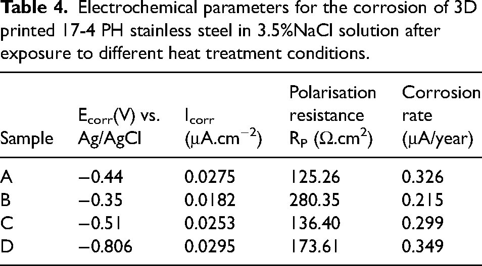
The results of the potentiodynamic polarisation curves of the 3D printed 17-4 PH SS in 3.5wt%NaCl solution at 25°C are shown in Figure 10. As shown, the four samples exhibit similar behaviour, indicating that heat treatment does not change the corrosion mechanism of 17-4 PH SS; the cathodic polarisation curves exhibit distinctly linear Tafel region whereas the anodic polarisation curves show the inflection point with two different slopes at potential more positive than the corrosion potential. The observation is associated with a kinetic barrier effect resulting from the deposition of corrosion products followed by dissolution at a higher anodic potential. On heat treatment, the curves shift to higher or lower current densities, indicating that the thermal fluctuations influence the corrosion rate of the 17-4 PH SS alloys. As shown, Sample B shifts to the region of higher potential and exhibits a smaller anodic active zone and larger passivation zone compared to the non-heat-treated sample A. Sample C slightly shifts to a lower potential region and is characterised by a larger anodic active zone compared to samples A and B. Sample D curve shifts to the lowest potential region and its anodic branch does not exhibit the passive region except a very small inflection. These observations indicate that there was a formation of a passivation layer followed by pitting in Samples A, B, and C. The observations further indicate that Sample B indicated attractive corrosion properties. The electrochemical parameters of the test were computed by Tafel analysis and presented in Table 4. On heat treatment, the corrosion potential, Ecorr, increased from −0.44 V (Sample A) to −0.35 V (Sample B), and then decreased to −0.51 V (Sample C) and −0.806 V (Sample D). Sample B indicates the highest polarisation resistance, lowest corrosion current density Icorr, and lowest corrosion rate. Sample D exhibits the highest corrosion rate and highest corrosion current density.
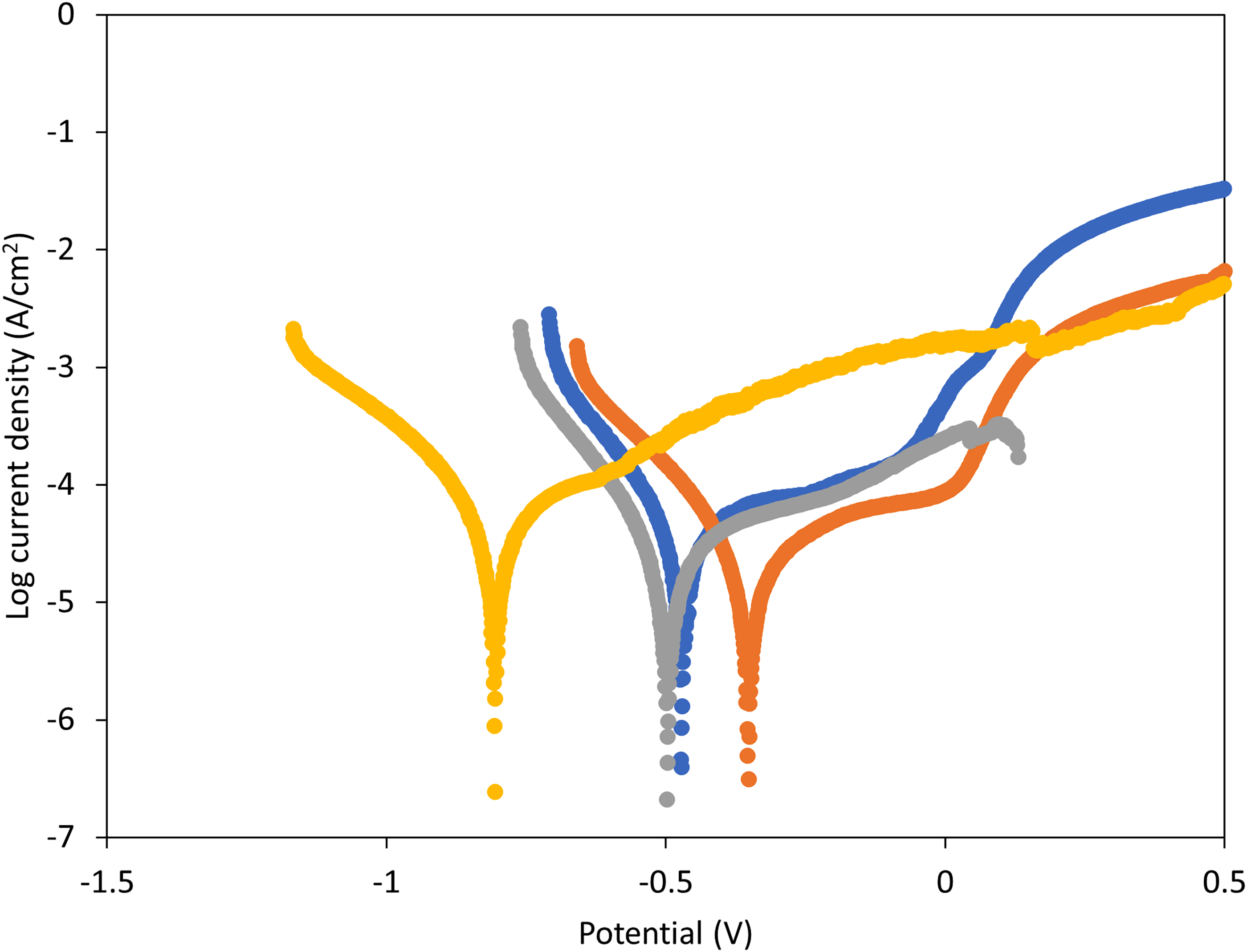
Potentiodynamic polarisation plots for the corrosion of 3D printed 17-4 stainless steel in 3.5% NaCl solution after heat treatment in different conditions.
Electrochemical parameters for the corrosion of 3D printed 17-4 PH stainless steel in 3.5%NaCl solution after exposure to different heat treatment conditions.
To evaluate the corrosion mechanism of the additively manufactured 17-4PH after heat treatment, the SEM and EDS were undertaken on the surfaces of the samples after polarisation tests in NaCl solution. As shown in Figure 11, there was an occurrence of pitting as well formation of lumps of corrosion products. The pits (indicated by white arrows in Figure 11) are observed in all the samples and their sizes and numbers vary across the four samples, indicating pitting corrosion dependence on the thermal fluctuations. The analysis of pitting via Fiji software (ImageJ, open access on: https://imagej.net/software/fiji/), as shown in Figure 12, revealed that the sizes of pits on sample A, B, C, and D were 0.425 μm, 0.409 μm, 0.163 μm, and 0.671 μm respectively. On the representative images (Figure 12), sample D had the largest number of pits whereas sample B had the lowest number of pits after corrosion in NaCl solution. Our analysis of the images revealed an average number of pits of 269, 98, 106, and 340 for samples A, B, C, and D respectively. Furthermore, the microstructures were characterised by both regular and irregular pits with samples A and D exhibiting mostly irregular pitting morphologies.
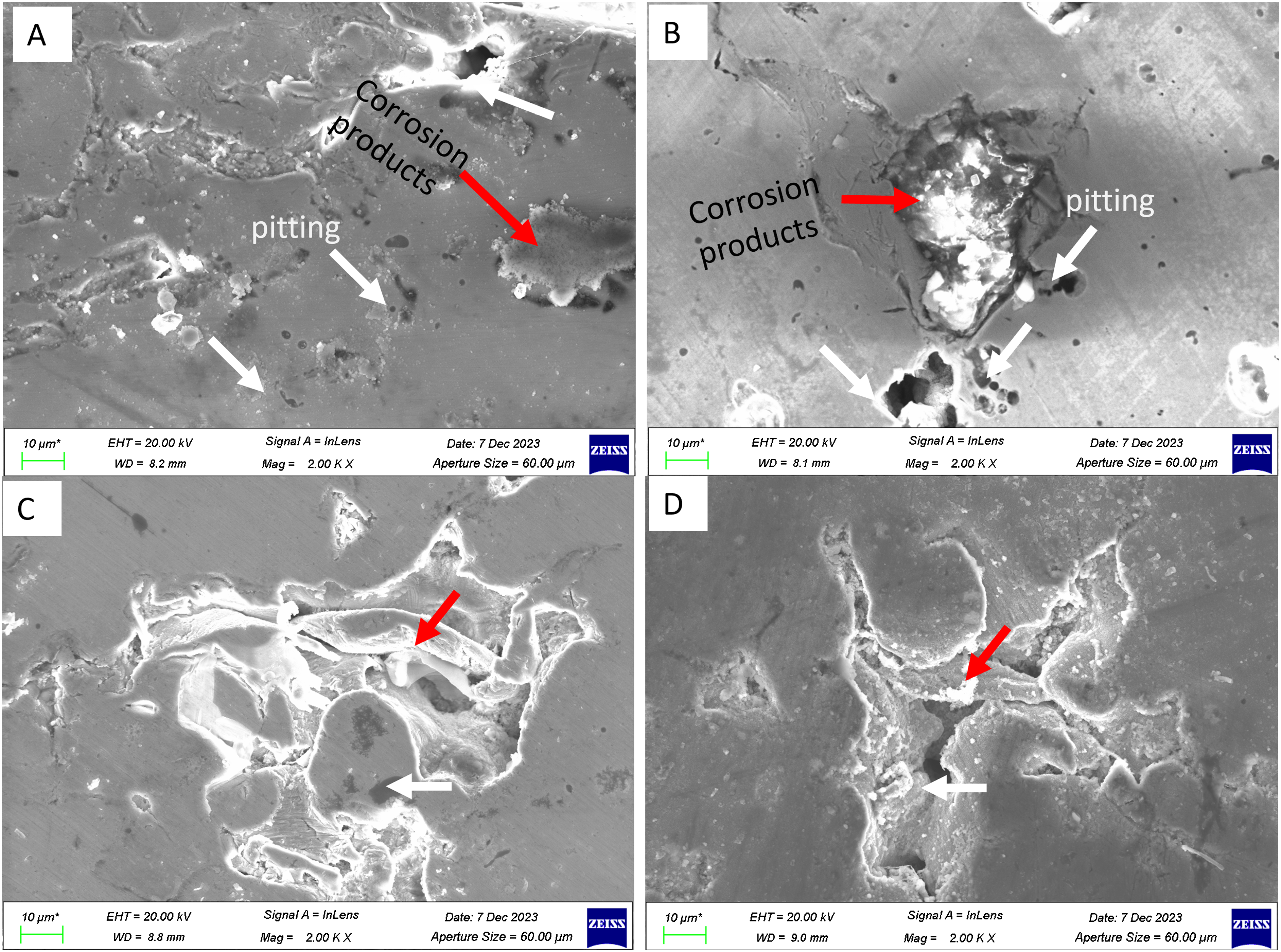
Morphology of the 17-4PH samples after polarisation tests in 3.5% NaCl solution. The white arrows indicate the pits whereas the red arrows show the corrosion products.
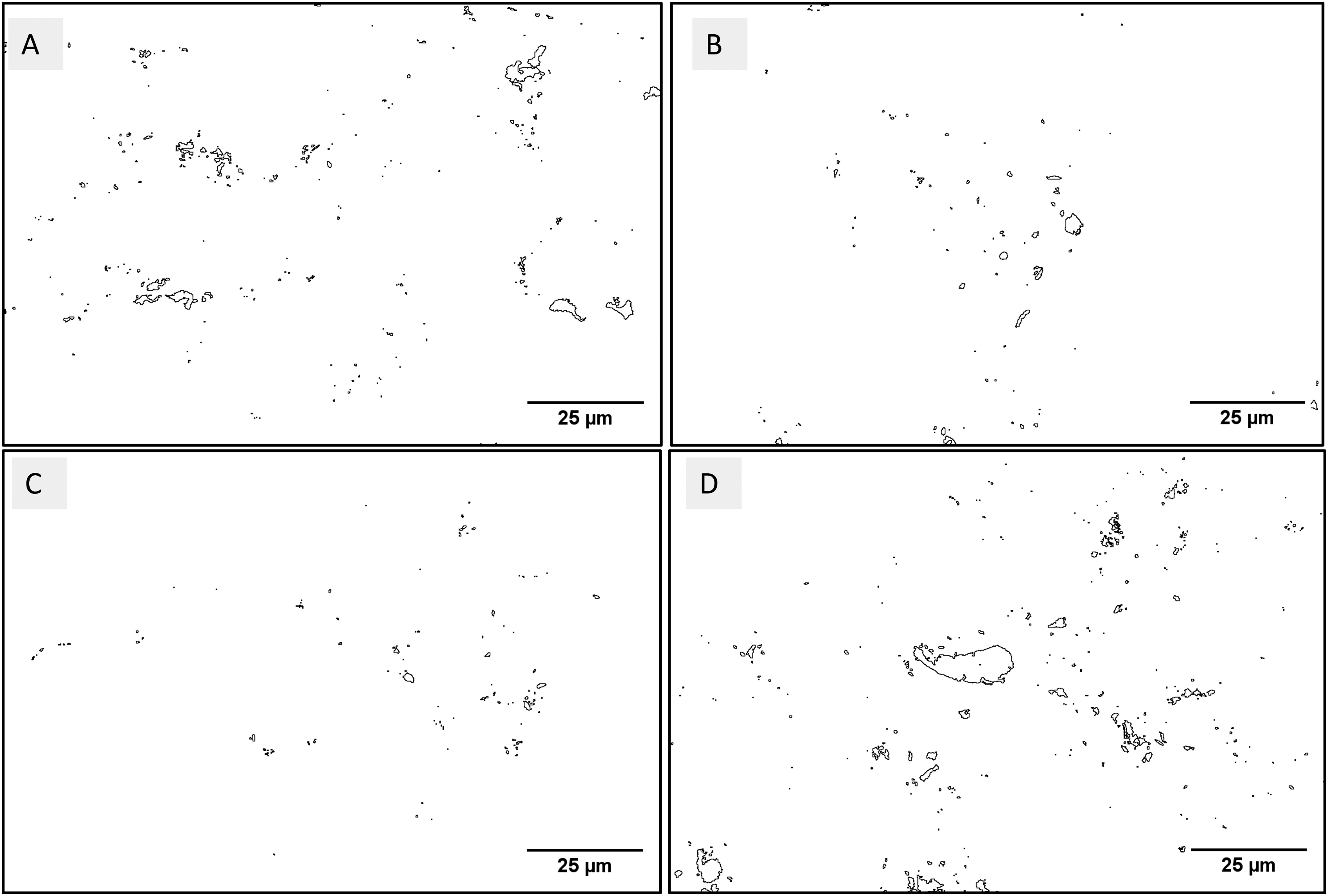
Analysis of pitting after polarisation tests of the 17-4PH stainless steel in 3.5% NaCl. The outlines represent the morphology of the pits on the surface microstructure.
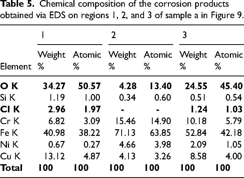
The red arrows in Figure 11 show the localised regions of corrosion attack on which corrosion products were formed. These regions appear on all the samples after the polarisation test in the NaCl solution. A further analysis of the localised corrosion regions (Figure 13) through Energy-Dispersive X-ray Spectroscopy (EDS) revealed presence of chlorides and oxides (Table 5). As shown in Table 5, the oxides and chlorides were present in regions 1 and 3 on which localised corrosion took place to form new compounds. These regions appeared as dark localised morphologies on the SEM images and demonstrate occurrence of chloride attack from the NaCl solution during the corrosion test.
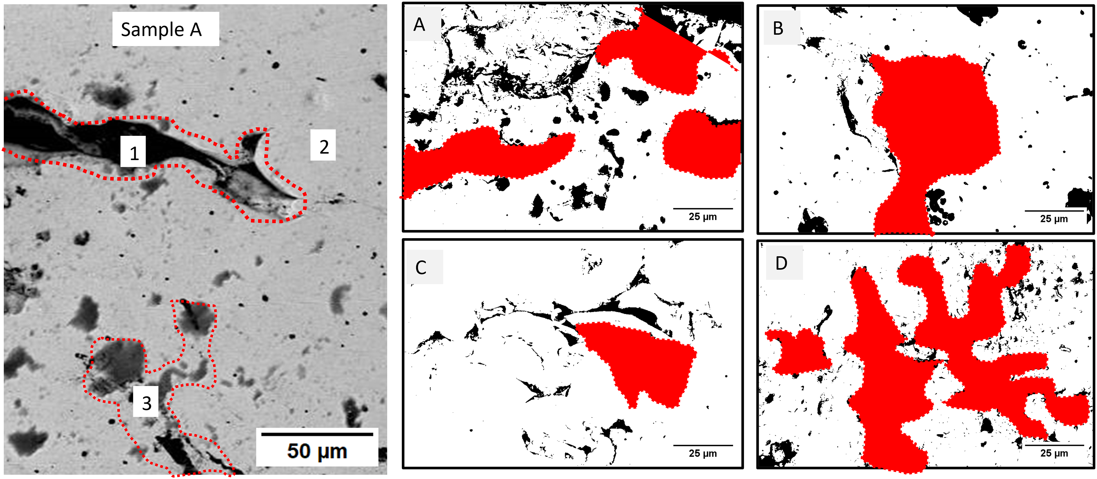
Analysis of pitting corrosion products on the surface microstructure of 3D printed 17-4PH stainless steel. The backscatter image for sample A on the left shows the regions on which the EDS was undertaken to evaluate the corrosion products. The images on the right are threshold SEM images for samples A, B, C, and D on which the red masked regions show the regions on which the corrosion products have been formed. These regions are consisting of oxide and chloride compounds resulting from corrosion attack by the NaCl solution.
Chemical composition of the corrosion products obtained via EDS on regions 1, 2, and 3 of sample a in Figure 9.
Based on these observations, the mechanism of corrosion of 17-4PH stainless steel manufactured via fused filament fabrication and exposed to thermal fluctuations (through various thermal treatment cycles), can be described as follows. On exposure to 3.5%wt. NaCl solution (at room temperature and air), 17-4PH stainless steel undergoes passivation, i.e., it forms a passive oxide layer due to oxygen present in the corrosion environment.
32
The passivation layer consists of Cr2O3 (region 2 in Figure 13 shows the passivation layer since it consists of oxides according to EDS results in Table 5). The passivation layer provides corrosion resistance by acting as a barrier between the metal surface and the surrounding environment. However, consistent exposure of the samples to the NaCl solution with the continuous current flow (during the polarisation test), leads to the release of chloride ions (Cl-) into the surface of the stainless steel. These Cl- adsorb onto the surface of the stainless steel and since Cl- ions are more aggressive than O + ions, they can compete with oxygen for binding sites on the metal surface. The adsorption or penetration of the Cl- ions may be assumed to take place through the pores, cracks or other printing defects discussed earlier in the paper. This results in chloride-induced breakdown of the passivation in which the Cl- ions penetrate the passive film and destabilize it by forming soluble metal chloride/oxide complexes. These regions are shown as
Conclusions
In this article, 17-4 precipitation hardening (PH) stainless steel produced via fused filament fabrication (FFF) was exposed to different fluctuating temperature conditions and evaluated for structural, mechanical, and corrosion properties. The following conclusions can be drawn:
Exposing sintered 17-4 PH SS to H900 aging temperature for 3 h resulted in the formation of precipitates in the martensitic matrix and homogenisation of the microstructure. Continued exposure (beyond H900 temperature) to different fluctuating temperature conditions resulted in agglomeration and inhomogeneity in the microstructure. The XRD analysis revealed the presence of retained FCC austenitic phases in the microstructure, which could be attributed to reduced hardness (mechanical strength) and corrosion resistance of the fused filament fabricated 17-4 PH SS upon exposure to fluctuating thermal conditions. It was shown that samples exposed to temperatures beyond the H900 condition exhibited the highest corrosion rate. In addition, the size and number of pits formed on these samples were larger than those observed in the samples exposed to H900 conditions. The EDS analysis revealed the formation of the corrosion products (e.g., FeCl2, FeCl3, Fe2O3, and Fe3O4) on the pitting regions.
These results demonstrate that prolonged exposure of FFF 17-4 PH SS to fluctuating thermal conditions results in structural transformation and degradation in mechanical strength and corrosion resistance.
It is suggested that detailed chemical and microstructural analyses are necessary, especially at prolonged exposure to the 3D printed 17-4PH SS in high temperatures for a deeper understanding of the mechanisms of degradation and corrosion. Other properties such as fatigue and wear should be considered in future studies at thermal fluctuating conditions.
Footnotes
Declaration of conflicting interests
The authors declared no potential conflicts of interest with respect to the research, authorship, and/or publication of this article.
Funding
The authors received no financial support for the research, authorship, and/or publication of this article.