
Abstract
Currently, in the manufacturing industry, there are many different component manufacturing processes. Each of them has its own advantages and disadvantages. One phenomenon present in some processes is known as warpage. Essentially, warpage is unwanted deformation in a component caused by internal stresses, thermal variations, uneven cooling of the part, the presence of moisture or the release of residual stresses in the material. Although it is a common problem in some engineering fields, it occurs mainly in processes such as injection moulding, compression moulding and 3D printing. There are different measurement and mitigation techniques that are adapted to each process. This paper discusses the causes of the phenomenon and current and future mitigation techniques. Additionally, an overview of upcoming techniques aimed at fully mitigating and measuring this phenomenon in real time during manufacturing processes is presented.
Definition and introduction
Over the years, the manufacturing industry has been forced to implement new processes or optimize existing processes. Owing to these updates, inconveniences specific to each process may arise. Engineers aim to reduce or nullify these unfavourable variables in search of continuous improvement in the quality of the manufactured parts.
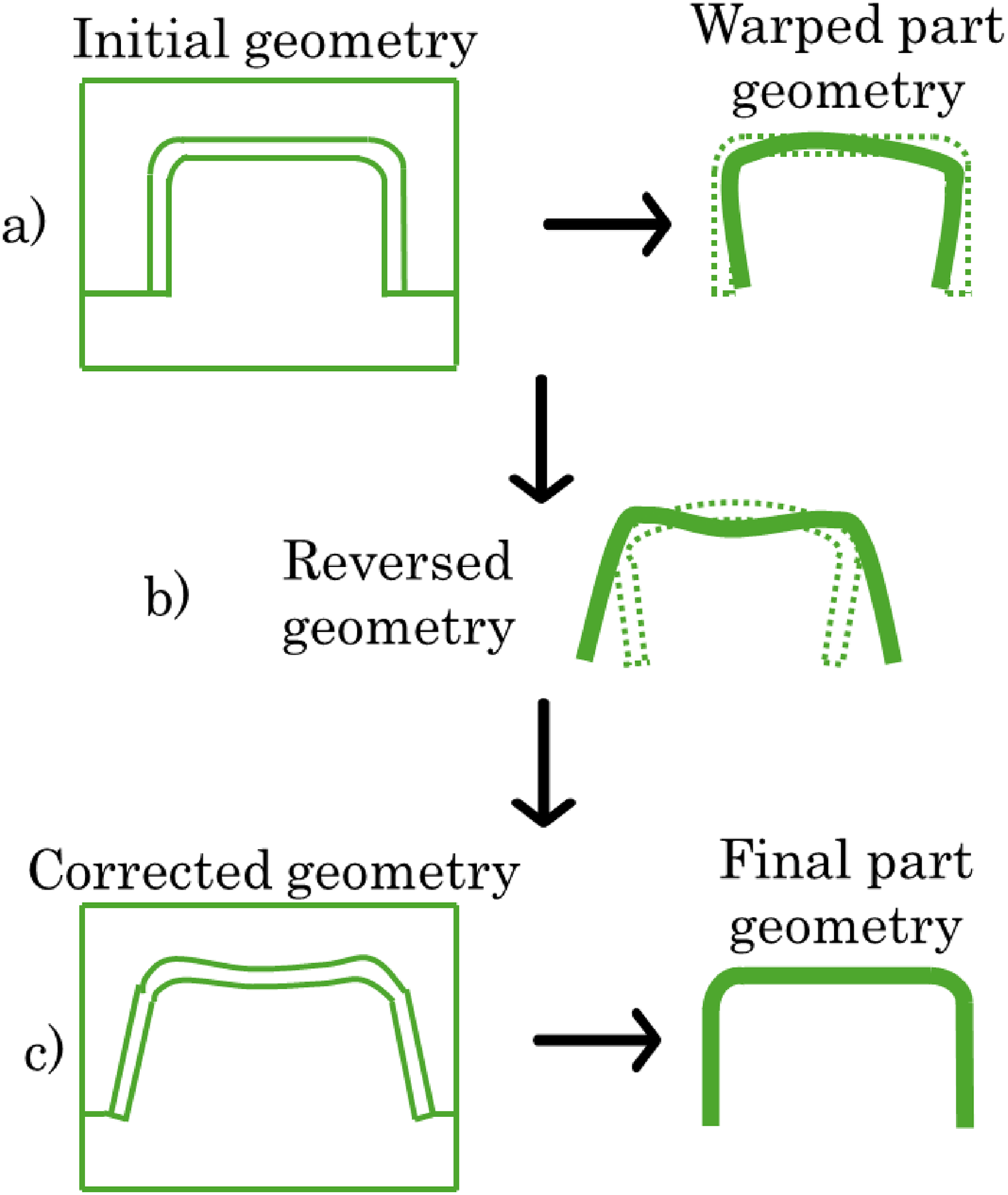
In this context, a recurring problem arises in engineering: warpage. Basically, this phenomenon is the deformation of parts manufactured via different methods. This deformation alters the shape of the components from their intended design. In large pieces, the effect of this phenomenon is more noticeable, although in very small elements, it also appears since its appearance does not directly depend on a single variable. Therefore, calculating and predicting the deformation field in a part due to warpage is a complex problem. As warpage depends on several manufacturing variables, determining which of them has the greatest influence is challenging. In most cases, multiple effects can counteract or increase their influence on each other, so isolating the contribution of each effect is difficult. Figure 1 schematically shows the different types of warpage that can occur in manufactured parts. Figure 2 shows real examples of this phenomenon. Notably, one or several can occur in each component. However, as mentioned above, it is difficult to predict which of them will be present on the basis of their characteristics and variables of the manufacturing process.
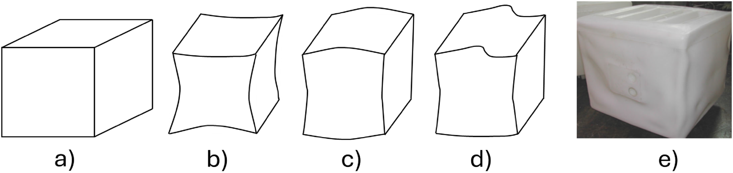
Types of warpage: (a) Expected shape, (b) Concave, (c) Convex, (d) Irregular, (d) Warped piece. 1
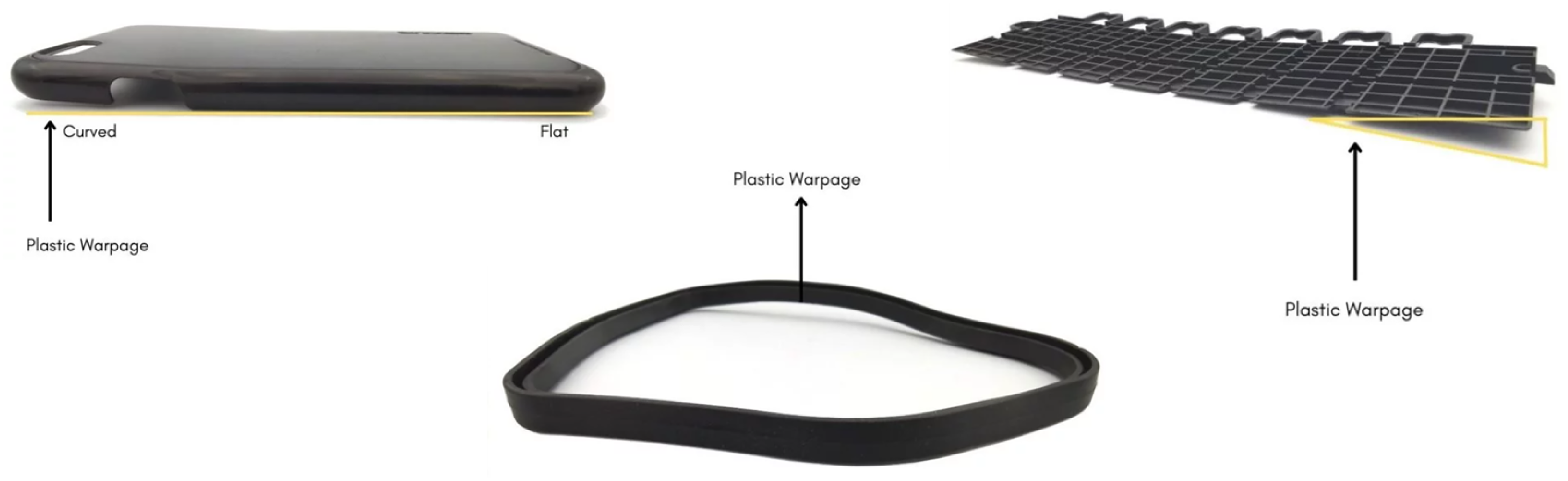
Examples of warpage occurring in different components. 2
Most of the research on this phenomenon has been carried out to determine which of the variables involved in each manufacturing process most influence the final warpage values. The possible causes can be separated into two groups: the raw material, which involves the physical, chemical and mechanical properties of the material, and the parameters of the manufacturing process, which, depending on the case, can include the moulding pressure, the cooling temperature, the print bed temperature, etc.
The literature 3 has defined warpage as deformation of the finished part, and historically, research investigating the factors associated with warpage has focused on a few manufacturing processes. Injection moulding, compression moulding and 3D printing will be analyzed in this document since they are the most relevant methods for studying this phenomenon since the effect of warpage on the final finished pieces is more evident than in other conventional processes.
This topic can best be covered under the headings mentioned above. This is exemplified in the work of Cheng, 4 whose analysis of the variables of the compression moulding process revealed that when the temperature of the cooling water within the core plates and cavity of the mould was varied, the deformation associated with warpage was reduced by approximately 80%.
In the analysis carried out in, 5 the importance of material selection in the 3D printing process is presented. Focusing on polypropylene as a raw material, several conclusions are reached that invariably return to the importance of all elements of the 3D printer maintaining a constant temperature. There should be no temperature difference between each layer of the element and the extrusion nozzle. A stable and constant temperature should be maintained in the environment throughout the process.
On the other hand, Mohan 6 analysed the variables that influence warpage during the plastic injection moulding process. This results in the mould temperature and packaging pressure having a greater influence on warpage. The cooling time and packing time are in the background, whereas the melting temperature and injection pressure are secondary values. Zhao 7 provided a more general perspective in his review work. The selection of materials, the design of plastic parts and moulds, and the adjustment and optimization of process parameters are the factors that can reduce warpage under proper analysis.
These are just some examples of how each process involves different variables that lead to the appearance of warpage. Hence the importance of studying each one separately in order to have a better perspective of the causes and solutions.
Given the relevance of these processes in the manufacturing industry, it is necessary to propose new mitigation, measurement, and optimization techniques. Currently, engineering focused on manufacturing has several challenges to meet in terms of research. On the one hand, artificial intelligence (AI) has emerged as one of the tools recently used to mitigate and predict the effects of warpage, with artificial neural networks (ANNs) used as the means to optimize manufacturing processes and parameters. Chen 8 proposed the use of autonomous learning from a database and implementing an AI algorithm. A precision greater than 95% was obtained. Compared with the traditional approach, the finite element method (FEM) considerably reduces the analysis time.
Another example of a novel technique is the case of Liu, 9 where the warpage deformation of a silicon wafer is monitored in real time via a distributed optical fibre. Furthermore, the influence of data resolution on the measurement result is studied. The experimental results show that this method has good precision and that the relationship between the data resolution and measurement error is nonlinear. Monitoring warpage in real time is proposed.
There has been remarkable progress in the development of new materials, such as advanced composites and polymers, which are used in various industries, including automotive and aerospace. These materials present unique challenges in terms of warpage, as their anisotropic properties and variability in manufacturing processes can increase the likelihood of warpage.
The development of advanced software and more accurate computational models, such as Moldex 3D, has evolved significantly. Reviewing and comparing these advances can provide valuable guidance for researchers and practitioners seeking to optimize their manufacturing processes, minimizing warpage.
Processes such as additive manufacturing (AM), or 3D printing, have gained popularity in recent years, and warpage is a common problem in this technology, especially in large or complex parts.
Warpage is a phenomenon that intersects with several disciplines: materials science, mechanical engineering, chemical engineering, and polymer science, among others. A review article can serve as a bridge between these disciplines, highlighting how different approaches and methodologies complement each other to address warpage.
This leads to the relevance of bringing all these factors together in a review article. Several aspects of warpage remain to be analyzed in detail, which will be addressed in the rest of the document.
Manufacturing processes and warpage
Before continuing, it is pertinent to correctly define the concept of warpage. This phenomenon should not be confused with shrinkage. As shown in Figure 1, there is no change in the dimensions of the object. Therefore, the following statement can be made: “Shrinkage is defined as a change in size. Warpage is a change in shape.” Exemplified in Figure 3, 10 warpage is the result of nonuniform shrinkage in parts. These are not material properties; rather, they are a consequence of the manufacturing process. Nevertheless, they do depend on the thermal properties and PVT relationships.
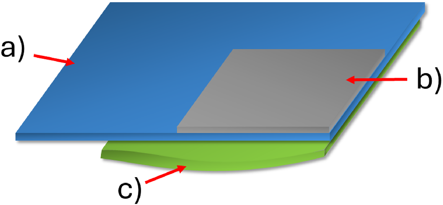
(a) Original part, (b) Part with shrinkage, (c) Part with warpage and shrinkage.
Once the concepts are defined, the variables that cause warpage can be classified on the basis of the manufacturing method.
Injection moulding
First, the method and machinery are described. The injection moulding machine consists of three main parts: a mould, a clamping mechanism, and an injection component. The process begins by clamping the two halves of the mould with the clamping unit. The mould must be sealed to resist the high pressure exerted during injection. Polymeric materials are commonly used for this method. Although recently fibre reinforced plastics (FRP) have found a boom due to the improvement in the mechanical and physical properties of the final component. Basically these materials are a combination of a polymer with non-rotated fibres of some reinforcement such as fibreglass or carbon. 11
The material, which is usually granular, is then introduced into the injection unit, where it is heated until it reaches a molten state. A screw or piston moves back and forth and then pushes the molten material through the nozzle into the mould cavity. The injection pressure and speed are controlled to ensure complete filling of the mould. Once the mould cavity is filled, the material begins to cool and harden. Cooling can be assisted by circulating coolant through channels in the mould. Proper cooling is critical for maintaining the desired shape and dimensional accuracy of a part. The cooling time depends on the properties of the material and the thickness of the part. Once the material has cooled and hardened sufficiently, the mould is opened, and the two halves of the mould are separated. Pins or plates push the finished part out of the mould cavity.12,13
Raw material selection
An inadequate selection of the raw material necessary for the process is capable of causing unwanted deformations in the final pieces.
Different materials have different shrinkage coefficients during the cooling process. If a raw material with a high shrinkage coefficient is selected, the part is likely to warp as uneven cooling occurs. In addition, anisotropy in shrinkage, typical of FRP where shrinkage varies in different directions of the material, can intensify this effect. Likewise, analysing the microstructures of materials, a slow rate of crystallization or a low degree of total crystallinity can reduce shrinkage and thereby reduce warpage in semicrystalline polymers. In contrast, resin of nucleated grades result in greater shrinkage and proportionally greater degrees of warp.3,14
For example, Divekar 15 used a warpage approach that considers the mechanical properties of a material as a function of temperature, proposing to include this effect in analyses and simulations. While Li 16 proposes a prediction method. Using multilayer models combined with the classical plate theory, it also predicts the Young’s modulus with the influence of temperature. With an error range of between 3 and 5%. However, there are still certain variations in the results. Gandhi, 17 better predicts warpage when more thermal properties of the materials are available. In this case, it uses polypropylene (PP) reinforced with 30% glass fibres using Moldex 3D software. Similarly, Deng 18 proposed a prediction method to analyse continuous fibre-reinforced thermoplastics in search of improved mechanical properties. FEM methods were proposed to simulate this addition so that the results would be more in line with the real phenomenon.
Using a different software, Lin, 19 analyses warpage in injection moulded parts made of FRP using Moldflow. A FEM model and experimental measurements are proposed. A more extensive approximation of the mechanical properties of the material should be included to obtain more coherent results.
Another aspect to consider is the uniformity of the composition of the raw material. Impurities or a lack of homogeneity in the material mixture can cause localized changes in the thermal and mechanical properties. Additionally, some materials tend to accumulate residual stresses during manufacturing, especially if they are not properly heat treated. 20 These stresses can be released unevenly during cooling.
This brings us to the next point. If the selected raw material has a narrow processing temperature range and is processed outside of this range, thermal stress can occur which contributes to warpage. Finally, some polymers are hygroscopic and can absorb moisture from the environment. Uneven moisture absorption can cause the material to expand unevenly, leading to warpage. Therefore, it is clear that the better characterized the materials are prior to processing, the better able to control and mitigate warpage.
Mould factors
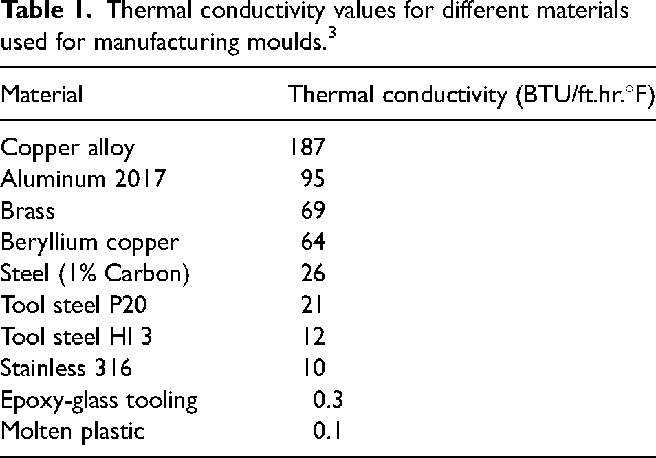
Taking into account factors such as geometries and materials is essential to mitigate the phenomenon. For example, the use of copper or aluminium alloys for cores and areas that form the inside corners of plastic parts helps achieve the greatest concentration of heat in these remote areas, consequently forcing them to cool at the same rate as the other areas of the mould. Concentrating more cooling in these critical areas also helps combat warping caused by differential cooling rates. 21 An example is the work of Lucyshyn, 22 whose results revealed a positive effect in reducing warpage when there is greater thermal conductivity in the steel of moulds made of this material.
For a better understanding, Table 1 shows different materials and their thermal conductivities. These materials are usually used for moulds. It is possible to compare them to determine which ones are better options for this purpose. The materials are arranged in descending order. As mentioned, copper alloys have the best thermal properties for functioning as a mould, followed by aluminium, some types of steel, and finally, plastics.
Thermal conductivity values for different materials used for manufacturing moulds. 3
Once the mould material has been selected, its geometry must be correctly determined. As with any mechanically manufactured part, certain tolerance recommendations must be followed. Figure 4 and Table 2 provide a general overview of the recommended tolerances for moulds that can be used in the injection moulding process. 23 This is a critical factor. For example, ensuring the unformed wall thickness ensures that the molten plastic cools uniformly throughout the mould, thus avoiding any plastic warpage defects. If there is any inconsistency in wall thickness, there may also be inconsistency in the shrinkage of the plastic resins. This is especially the case if there are high levels of pressure loss in thin and thick walls within the mould. Wang 24 in thin-walled parts made of polycarbonate (PC), the mold and process parameters are optimized using Moldflow software. The maximum warpage value was improved by 69% and it is shown that this occurs during the injection process due to uneven shrinkage.
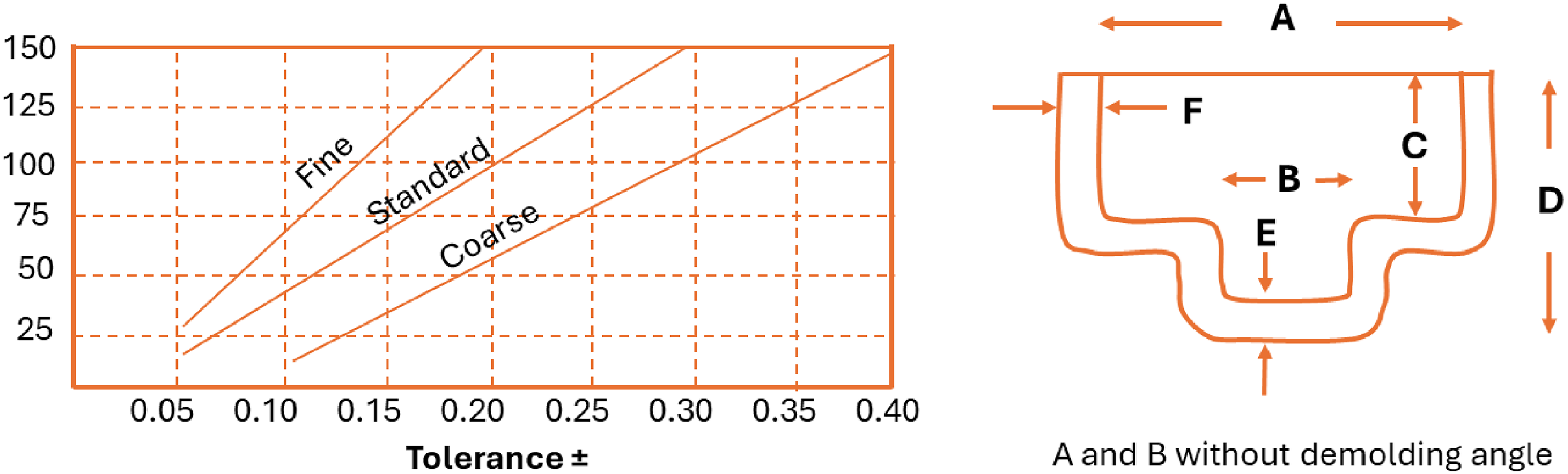
Suggested dimensions in mm and part dimensions for moulds in the injection moulding process.
Specifications for mold tolerances.
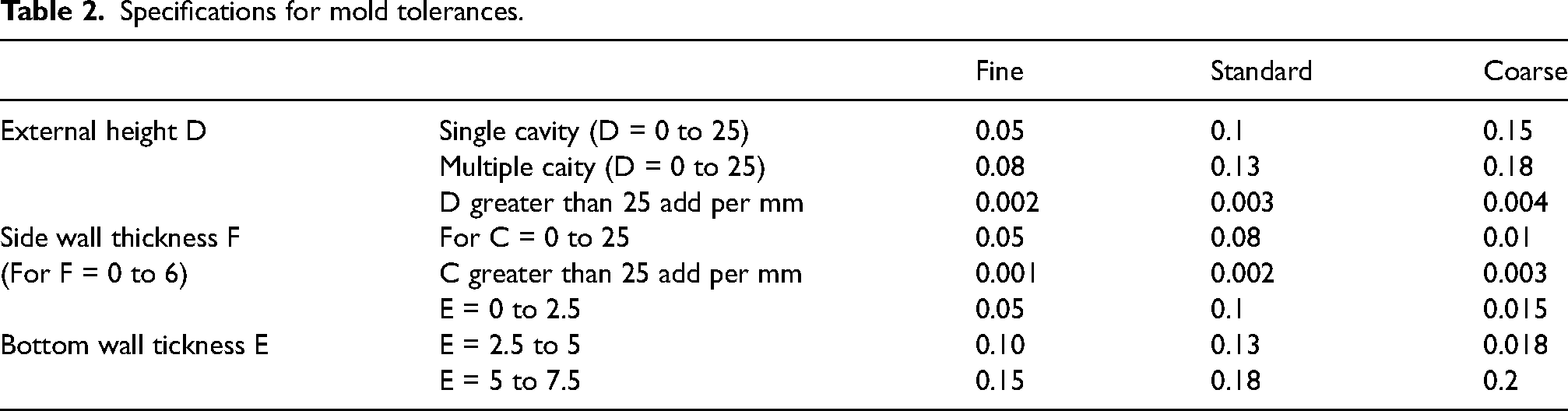
To exemplify the data presented, Tillmann 25 implemented regression to reduce and optimize warpage analysis via the FEM, modifying the original shape of the mould to avoid warpage at the end of the injection moulding process. This process is shown in Figure 5.
Scheme for correcting geometry to reduce warpage.
The next important factor to consider is the location of the gate. Correct positioning can ensure reasonably uniform shrinkage throughout the part. An example of this is the case for the FRP injection parts. As these parts are reinforced by fibres, the direction and positions if the fibres must be guaranteed. If the part has a side gate, the flow along the gate will be parallel to the longitudinal axis, whereas the flow on the opposite side is almost perpendicular to the long axis. The end result for an FRP material is that the part arches convexly on the side of the gate. Figures 6 and 7 shows some examples of good and poor position gate designs. Each arrow simulates the position and flow of the inlet gate. By placing fewer inlet gates that are all in the same direction, it is possible to generate a continuous flow of fibres in one direction only. While placing side gates generates random positioning of the fibres, consequently, the shrinkage is not uniform and warpage occurs. This has been observed in the case of Dongyou 26 where the warpage decreases as the fibre content increases in water assisted injection moulding, a Taguchi analysis was performed to determine the optimum combination of parameters, both process and fibre content. This is also briefly illustrated by Li. 27 In FRP, Moldflow software and neural networks are used to compare and analyse the fibre parameters and the process parameters themselves. As a result, the fibre parameters are more important than the process parameters in terms of influence on final warpage values. Similarly, Sadr Kenari 28 established a relationship between the percentage of glass fibres in the PP element and bending, flexure, and warpage. Likewise, Huang 29 analysed the influence of fibre orientation on warpage. Additionally, Šunje 30 concluded that contraction cannot be eliminated but must be uniform. Contraction occurs deferentially in the direction of the flow and perpendicular to the flow.
Different gate positions: (a) Poor design, (b) Poor design, (c) Good design.
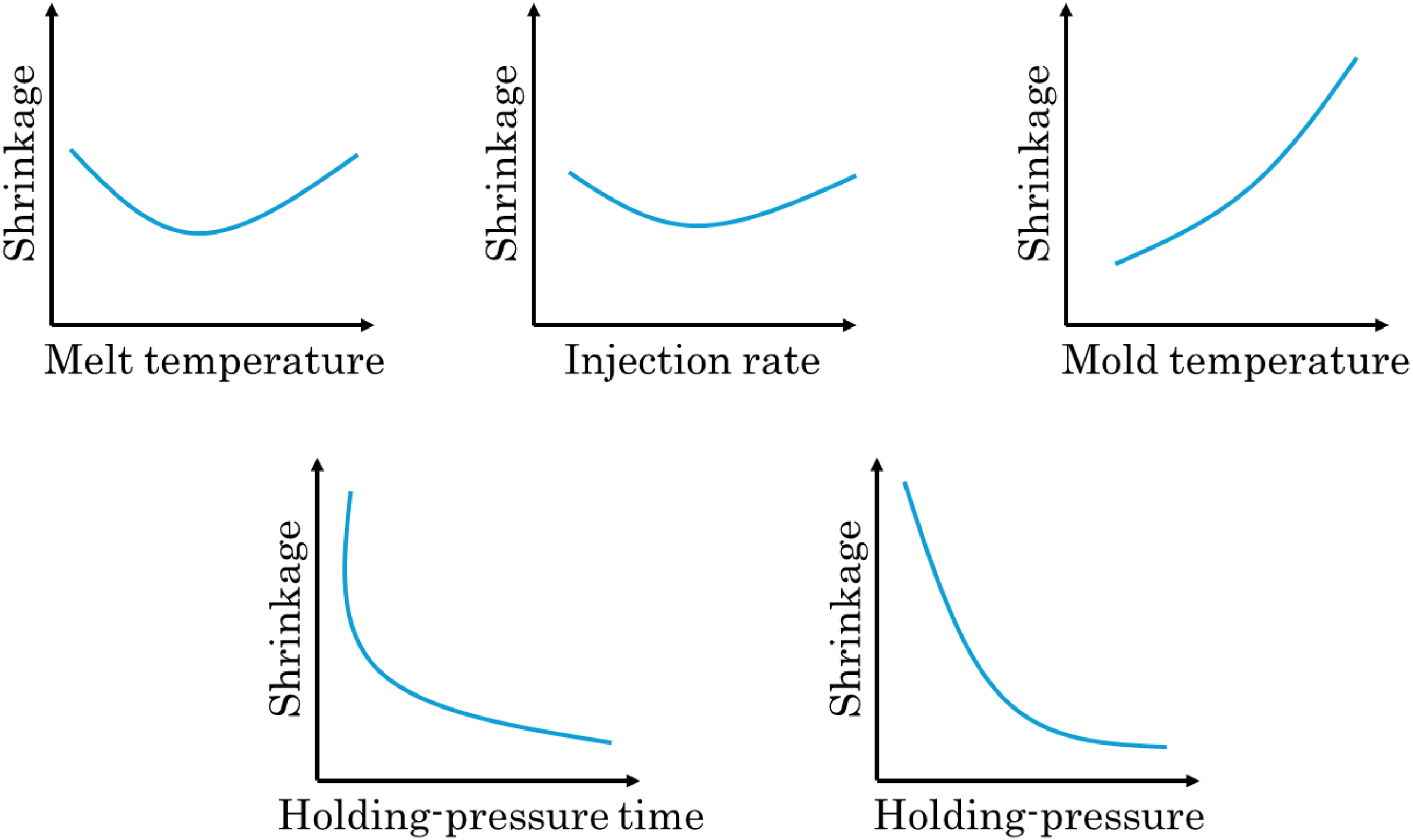
Behaviour of some factors of the injection moulding process machinery with respect to shrinkage.
The next most common cause of mould errors is setting the mould to an incorrect temperature. The mould temperature must match the temperature of the material. This ensures that the material flows throughout the mould and fills the mould. Mould surfaces that are in contact with the molten plastic should also be checked to ensure that the temperatures throughout the mould are uniform. Lin 31 provides a good illustration of this phenomenon. A statistical analysis is performed to relate the input variables to warpage. The mould temperature has a greater influence on microsized parts. The raw materials used in the study for the manufacturing of the parts were polyoxymethylene (POM), Acrylonitrile Butadiene Styrene (ABS), PP, and polyamide (PA).
The next step in the manufacturing sequence is the part cooling process. This is done by means of cooling channels. The positioning, size, and type of coolant used are essential variables to guarantee correct and uniform cooling, reducing the temperature gradients that cause residual stresses, which are among the main causes of warpage.
An important scientific aspect that must also be taken into account is that turbulent flow in coolant lines is much more efficient than laminar or aerodynamic flow in transferring heat from the mould to the coolant. Turbulent flow begins to occur when the Reynolds number (Re) is in the range of 2200 to 4000 in the following equation, where v is the fluid velocity in metres per second, d is the channel diameter in metres, and K is the fluid viscosity in metres per second. It is recommended that the system be designed to operate at a Reynolds number greater than 5000.
3
Notably, in liquids, the viscosity decreases at higher temperatures. Therefore, the coolant temperature is an important parameter to consider.
Machine factors
Numerous parameters related to pressure, temperature, and time are involved in the manufacturing process. Inadequate estimation of these values can result in increased warpage.
When analysing the melt temperature, at low temperatures, the plastic barely fills the mould cavity before the door freezesand the gate is clogged by solidification of the material. The pressure gradient from the gate to the end of the flow is high, and the time to fill the cavity is not significant. At high melt temperatures, much shrinkage is inherent as a result of the temperature change.
Another parameter is the injection rate. If injected at a lower speed, the residual stresses in the moulded part will be greater. A lower injection rate causes the material to have a lower viscosity; thus, a higher injection pressure is needed to push the material into the mould cavity. Conversely, a high injection speed can result in the material having a high shear rate at the inlet. If the shear rate is too high, it increases the internal stress of the part, causing it to deform.
The next parameter is the injection speed. A high injection speed ensures that the molten polymer fills the mould more quickly, which can help prevent premature solidification and ensure more uniform filling. High velocities can cause turbulent flow and create higher shear stresses within the material. It can also cause jetting, where the polymer stream forms distinct lines or waves, causing nonuniform filling and increased internal stresses. Fast filling means that the molten polymer has less time to cool before the mould is completely filled, resulting in a more uniform temperature distribution. Rapid injection results in a higher initial pressure, which can help pack more material into the mould cavity and reduce the number of voids. However, it can also introduce more residual stresses, which contribute to warping.
A low injection speed can result in a more controlled and stable flow, reducing the likelihood of turbulence and shear-induced stresses. However, if the speed is too low, parts of the polymer may begin to solidify before the mould is completely filled, causing uneven shrinkage and deformation. Slower speeds give the polymer more time to cool and solidify during the filling process, potentially creating a temperature gradient throughout the material. Slower injection can result in a lower initial pressure and potentially less effective packing, resulting in voids and uneven density. On the other hand, a reduced initial pressure can lead to lower residual stresses, which could help reduce warping if managed correctly.
Controlling the interaction between the packing pressure and packing time is essential for controlling deformation. An optimal combination of packing pressure and time is essential to balance the material flow, solidification and cooling rates to minimize warping. For example, using a pressure profile that gradually decreases the packing pressure over time can help control residual stresses and reduce warpage.
Illustrating the explanation above, where it is possible, a behaviour between shrinkage and some parameters of the process should be created, remembering that nonuniform shrinkage causes warpage.
Summarizing the influence of parameters. Trinh 38 and Liang 39 analysed and categorized the influence of input parameters on warpage. Hiyane-Nashiro 40 analysed the melting temperature, filling time and mould temperature, comparing statistical methods to reach the best relationship between the input variables and output variables, which are warpage and shrinkage in plastic pieces. Similarly, Saedon 41 performed a Taguchi statistical study to determine the best combination of properties to reduce warpage and size shrinkage in parts. The fusion temperature was found to be the most relevant parameter in warpage. Azad 42 reported that, in square pieces of polyethylene and wood, the packaging time and fusion temperature are the most relevant parameters.
Finally, three similar studies are those by Mohd Hanid, 43 Tamizi, 44 and Song. 45 They used the response surface method (RSM) to analyse the influence of the variables. The coolant temperature, fusion temperature and cooling time, in that order of importance, affect warpage. Two types of cooling channels are analysed. When recycled materials are used, the packing pressure is the most relevant parameter. It is concluded that the variables that significantly affect the amount of warping and volume contraction are the melting temperature, holding time, injection time, and cooling time.
Compression moulding
Compression moulding is a manufacturing process used to mould FRP, thermoset materials and some thermoplastics into defined shapes through the application of heat and pressure.
Initially, the material to be moulded, which may be in the form of powder, granules, preforms or tablets, is prepared and, in some cases, preheated. The mould is subsequently cleaned, and a release agent is applied to facilitate the ejection of the final product. The mould can be preheated to improve the material flow and reduce the cycle time. A measured amount of the material is placed in the mould cavity. This material must be distributed evenly to ensure good product formation. The mould is closed, and pressure is applied. The pressure and temperature depend on the material and mould design.
For thermoset materials, heat causes a chemical reaction that cures the material, whereas for thermoplastics, the material melts and takes the shape of a mould. The pressure and heat are maintained for a specific time to ensure that the material cures (thermosets) or cools and solidifies (thermoplastics) properly. For thermoplastics, the mould and material are cooled before the mould is opened. Once the material is cured or cooled, the mould is opened. The moulded part is ejected from the mould via an ejector system, such as ejector pins or plates.46–48
Since compression moulding is a less commonly used method, the main causes of deformation can be summarized as follows. Nonuniform distribution of materials. . This can occur because of improper material placement or inadequate compression force. Nonuniformity in the cooling of the piece. Inadequate or nonuniform cooling of the part can cause differential shrinkage and lead to warping. Rapid cooling or improper cooling techniques can cause varying shrinkage rates in the part, causing it to warp. Uneven mould temperature. Fluctuations in the mould temperature can cause variations in the curing process, resulting in different degrees of material shrinkage. Variations in shrinkage rates can cause dimensional inconsistencies and warping. Residual stresses. During the compression moulding process, internal stresses can accumulate within the material as it cures and solidifies. The release of these internal stresses during demoulding or cooling can cause the part to deform. Mould and ventilation design. Inadequate ventilation or an improper mould design can cause air or gases to become trapped inside the part during the curing process. This can create an uneven pressure distribution and cause warping.49,50 A work related to this process is that of Kim, 51 where the accuracy of simulations is improved by using the mechanical properties related to the temperature and Poisson’s ratio of the constituent materials in electrical microcomponents. Likewise, Sonmez 52 analysed the warpage of a PP piece with Moldflow software. Taguchi analysis was used, and the results were compared with experimental measurements to validate the FEM model.
3D printing
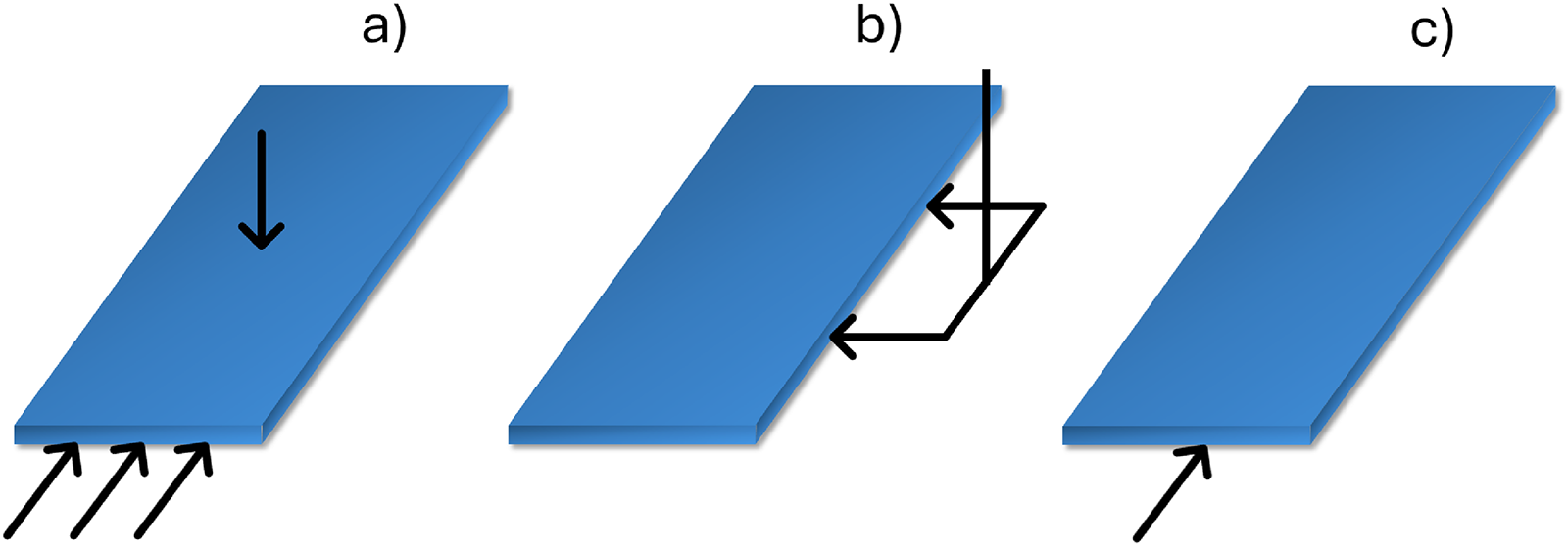
The printing process is based on fibre deposition modelling (FDM), fused filament fabrication (FFF) for plastics, and laser powder bed fusion (LPBF) for metals. The temperature of the base material is increased almost to its melting point, and once this point is reached, it passes through the extruder and is placed using patterns established with the nozzle. The process is repeated layer by layer until the desired geometry is achieved. This manufacturing method begins by first printing the layers along the perimeter. The interior space of the perimeter is subsequently filled by placing it layer by layer in the orientation predetermined by the user. Figure 8 shows a schematic of the warpage behaviour during the 3D printing process.
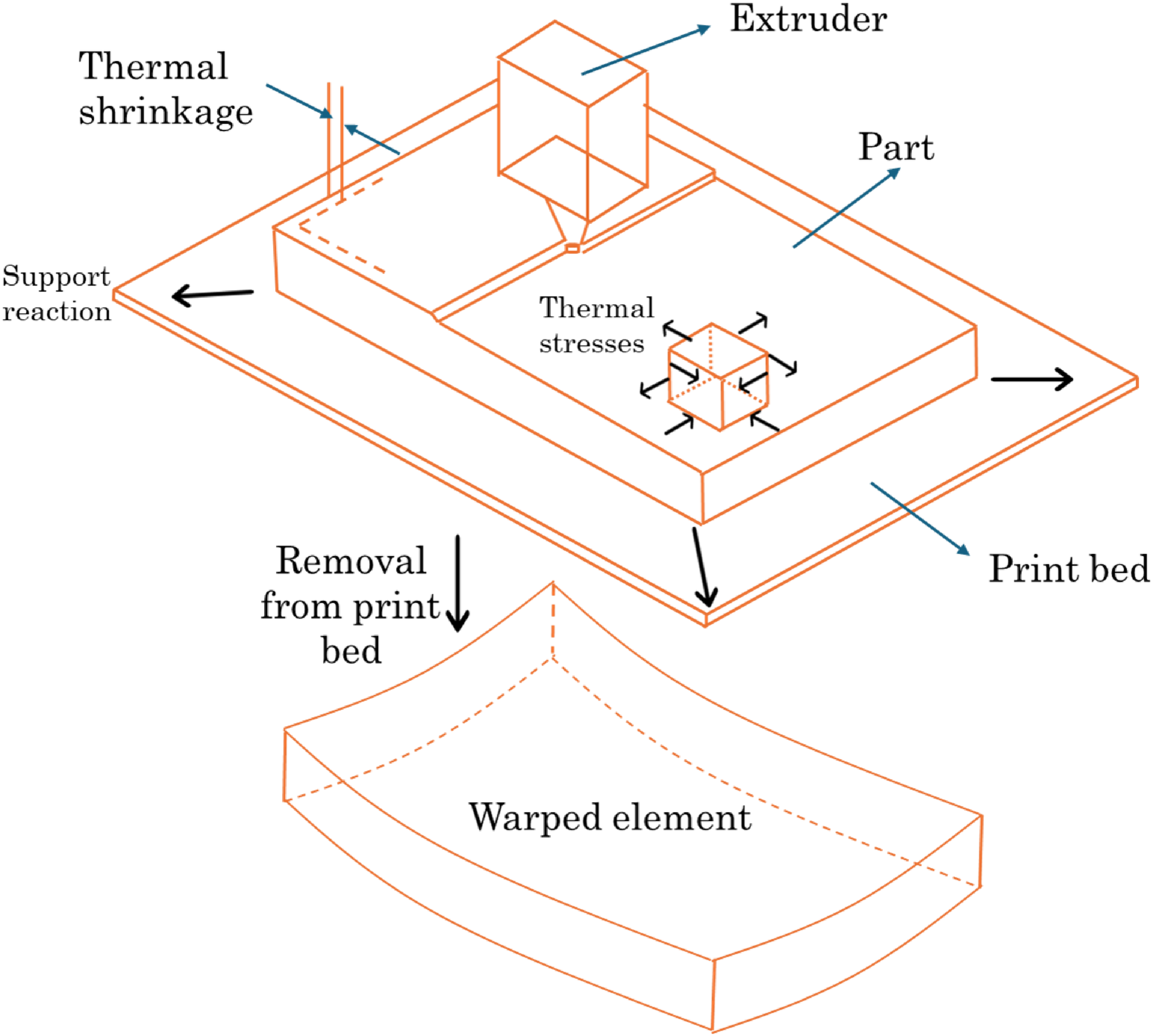
Warpage occurring during the 3D printing process.
As noted above, the causes of warping are inherent to each process. 3D printing methods can be classified into four large groups: uneven cooling, material properties, inadequate adhesion to the printing base, and printer parameters. As a general approach, Kitayama 53 and Mukhtarkhanov 54 developed a method for analyzing the influence of several parameters on warpage, providing a general overview and only the cooling parameters, respectively.
In the case of uneven cooling, when the material cools too quickly, different parts of the print can contract at different rates, creating internal stresses that cause warping. This is particularly common with materials such as ABS, which have high coefficients of thermal expansion. Additionally, if the print bed or environment is not heated evenly, different cooling rates in the print can cause warping. Heated beds can mitigate this problem by keeping the print bed warm and reducing the temperature gradient. In this sense, Banerjee 55 concluded that keeping the glass transition temperature and the bed temperature close has a significant positive effect on the parts manufactured via the FDM method. The variables of the manufacturing process are analysed to establish a relationship with warpage using MATLAB software. In addition, in the FDM process, Kuo 56 reported that bed temperature and chamber temperature are the main factors that affect warpage, and the Taguchi statistical method was used to determine the optimal combination of parameters.
In terms of material properties, for example, different materials exhibit different degrees of shrinkage when cooled. Compared with polylactic acid (PLA), materials such as ABS are more prone to shrinking and therefore warping, which results in lower shrinkage. Additionally, some filaments, such as nylon and polyethylene terephthalate glycol (PETG), absorb moisture from the air. During printing, absorbed moisture can cause inconsistent extrusion and lead to warping. Several studies have analysed this topic. With a theoretical approach, Sreejith 57 developed a mathematical approach to predict residual stresses in amorphous polymers. Spoerk 58 and Fitzharris 59 analysed the influence of materials on warpage and found that the coefficient of thermal expansion (CTE) in the FDM method is the variable that has the greatest influence on warpage.
Similarly, Austermann 60 and Amiri 61 improved raw materials with fibres (FRP). Austermann J. proposed that PP be modified with glass fibres and glass particles and found that warpage is reduced when glass fibres are added; however, the material in its pure state has better thermal conductivity. Amiri A. studied ABS complemented with glass fibres to improve its mechanical properties.
Inadequate adhesion to the build bed occurs when the first layer does not adhere properly to the build bed; subsequent layers can pull the edges of the printed part up as they cool and contract, causing warping. Ensuring a well-levelled base and using adhesives such as glue sticks, hairspray, or specialized building surfaces can improve adhesion. Agbayani 62 used high-density polyethylene as a 3D printing filament; since it does not adhere to the bed, the filament was modified with different components. Poor adhesion causes warpage, and wood flour reduces this formation.
Warpage behaviour is also associated with different factors of 3D printing. All the settings and parameters involved in the process can affect and cause deformations. Which variables you can control depends on the printer and the software. High layer height and printing speed values may exacerbate warping. The lower layer heights and slower velocities allow the material to cool more evenly, reducing the likelihood of warping. Fill densities can create internal stresses that cause warping. Using less dense fill patterns can help reduce these stresses.
Several studies have been conducted to analyse the influence of these parameters. Let us begin with Alzyod 63 using polyetherimide (PEI), ABS, and polyamide 6 (PA6). The filling density and printing temperature play crucial roles in reducing the residual stress of PA6 during filling. The pattern parameter proves to be an important contributor to minimizing warping deformation in all materials. Similarly, in the study by Samy, 64 3D printing variables related to warpage were analysed, and the printing speed was the factor that had the greatest influence on warpage, whereas an increase in ambient temperature affected warpage by only 1%. Similarly, Bachhar 65 analyses the variables in the FFF process. The relationships between the filling percentage and warpage and the tensions generated were observed. Warpage increases as the fill percentage increases. A factor that does not belong to the process itself is the geometry and thickness of the components. In these terms, Jiang 66 compared warpage with two completely opposite geometries, a square and a circle, resulting in greater warpage in the corners of the square due to the concentration of stresses. Lu 67 reported that, in thin-walled elements manufactured via the LPBF method, the greater the thickness is, the greater the warpage, and in open sections, a similar increase is observed. Similar findings were presented by Armillotta. 68 In the FDM method for ABS plates, geometric variables are analysed with respect to warpage. In this case, there is more warpage when more material is used to make a piece; the thinner the piece is, the less warpage there is.
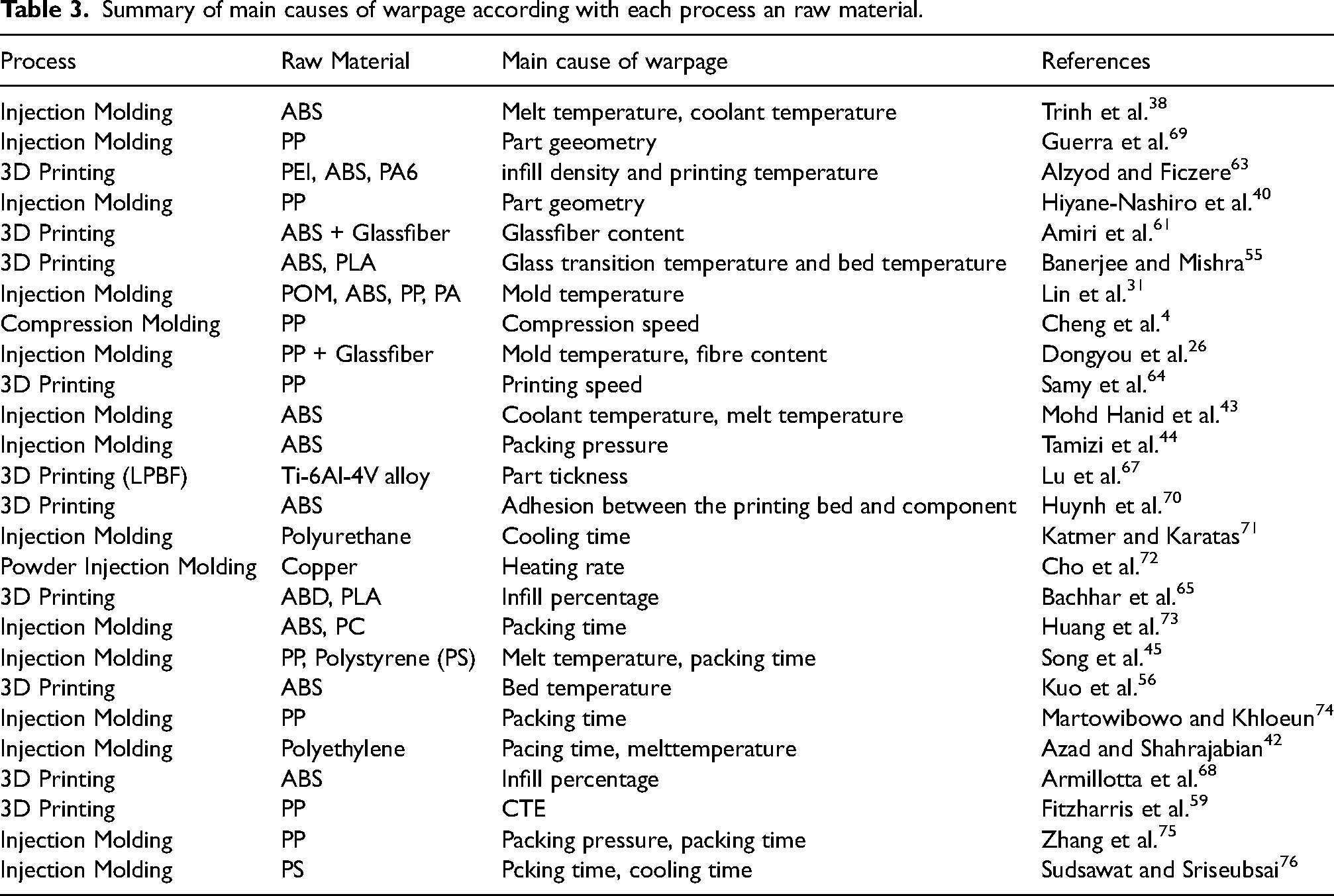
Grouping the main causes of warpage in a general way, it is possible to classify them into three large groups, independently of the process, as shown in Figure 9. Likewise, Table 3 shows in more detail the specific causes of warpage and how these relate to the raw material and the specific process. It is possible to find some trends such as that in 3D printing, the temperature of the printing bed and the percentage of infill are usually the predominant factors. While in injection molding, aspects such as packaging pressure or melting temperature are the ones that have the most influence.
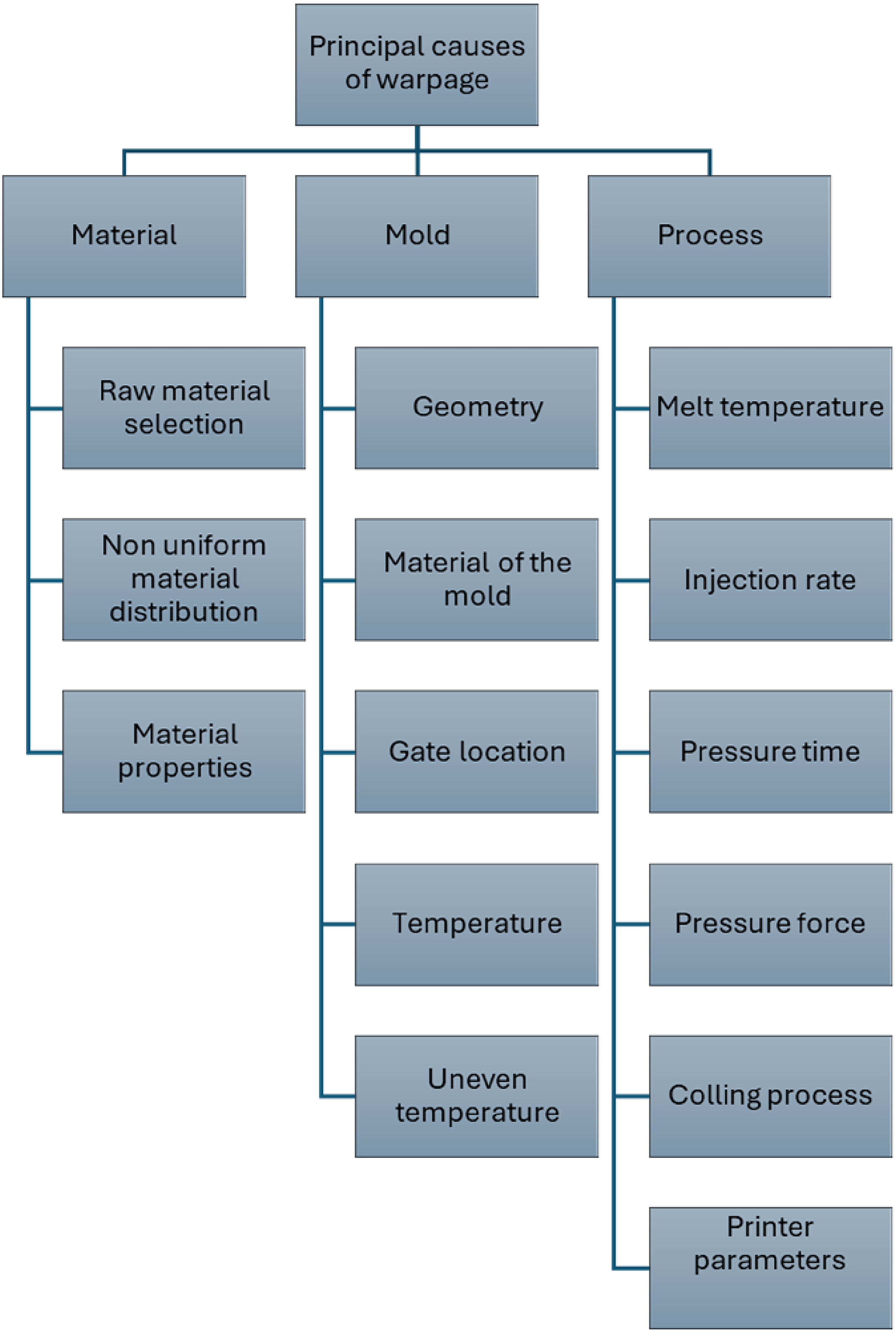
Summary of the causes of warpage.
Summary of main causes of warpage according with each process an raw material.
Mitigation strategies
Warpage mitigation is a complex process that involves the interaction of multiple factors, from part and mold design to material selection and precise control of process parameters. For each process, there are a number of actions that help reduce the presence of warpage. These actions range from varying certain process parameters to redesigning moulds or the component itself.
It is not possible to give a single solution to each aspect, since assuming that this action will completely mitigate warpage is wrong because it depends on many factors. However, the main actions that have been shown to yield positive results in mitigating the phenomenon can be summarized. These actions are summarized in Table 4.
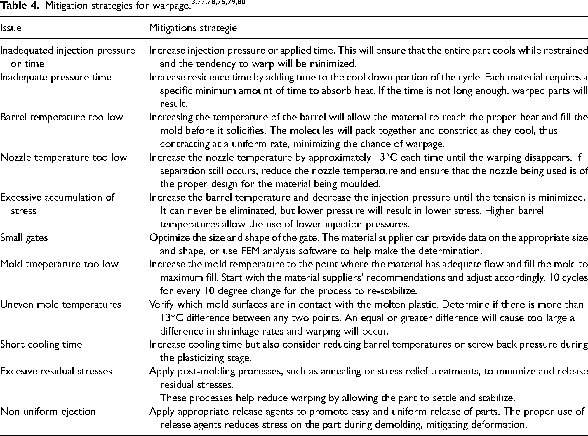
The actions listed above work as specific mitigation techniques. Individually they do not succeed in eliminating warpage. To achieve this goal, it is necessary to combine several or find new ones. This is the topic addressed in the next chapter, novel techniques to try to eliminate warpage permanently from components.
Future directions and research challenges
The problem of deformation in manufacturing processes such as injection moulding, compression moulding and 3D printing presents several avenues for future research and technological development. Addressing these challenges requires a multidisciplinary approach involving materials science, mechanical engineering, computer science, and manufacturing technology. New technologies such as AI have emerged as emerging tools that are capable of combining various disciplines in order to improve manufacturing processes. Techniques such as the use of optical fiber, infrared cameras or devices that send data in real time are some of the solutions proposed to deal with this phenomenon.
Artificial neural networks (ANNs)
The growing implementation of technologies related to AI has taken over many engineering sectors, and manufacturing processes are no exception. Currently, several studies have applied ANNs to find an optimal combination of manufacturing parameters and minimize the effect of warpage. Cheng 81 used ANNs to predict the magnitude of warpage on the basis of the values of the manufacturing process variables. Under the same concept but without prediction, Nitnara 82 established an optimization of the input variables of the manufacturing process to reduce warpage through neural networks and the FEM.
Similarly, Chen 83 sought to analyse warpage with FEM models using AI to improve predictions in microelectronic component packaging. The same philosophy is applied but now to a real case study. Liu 84 analysed the influence of several variables on a drone propeller pipeline via a genetic algorithm, and warpage was reduced via this method.
One of the great discoveries of the implementation of this type of technology occurs in the work of Kastelic, 85 where an algorithm is proposed that modifies the geometry of the cavity to compensate for warpage, and good results were obtained. In only 3 iterations, it is possible to reduce warpage by 99
Another example of this type of application is found in the research of Liu, 22 where a statistical analysis is carried out to determine the influence of different parameters on warpage. To further illustrate the prediction accuracy of the model, in response surface methodology, a back propagation neural network (BPNN) model and a genetic algorithm-based model (GA-BPNN) are taken as comparative algorithms. A 1% error is obtained when comparing simulations with Moldflow software. Finally, using the Response Surface Methodology (SRM) the methodology that explores the relationships between several explanatory variables and one or more response variables, Ryu 86 and Sreedharan 87 analyze the variables of the manufacturing process. In the same sense an important finding is mentioned in Sudsawat 88 uses a Firefly algorithm with better results than the genetic algorithm. Similary Jain 89 uses Human Behavior Based Optimization (HBO) which does not have large stochastic components and a fast convergence rate, also finds a slight improvement over the genetic algorithm.
Strategies for reducing warpage
There are cases when classic techniques are not sufficient to mitigate the effects of warping, then alternative strategies are proposed to optimize the process. This is the case for Vermes. 90 In this research, warping is compensated with the design of compensatory tools, intentionally modifying the geometry of composite materials in laminates, generating mechanical work through this method. Takesawa 91 analysed warpage in a 3D printing process of metal powders, where the density of the network and the orientation of the “shading” were modified, achieving reductions of 23 to 34%. From a numerical approach, Darby 92 proposed a new FEM analysis method using Moldflow software, where the nonlinear mechanical properties of materials that are dependent on temperature and time are taken into account. Accuracy was improved by 12%. Moretti 93 analysed the force with which the extruder was repelled from the bed in a 3D printing process, and warpage was monitored in real time. A method to take this factor into account and reduce warpage through the use of “digital twins” was proposed. Working with FRP materials, Collins 94 reported that warpage decreases as the thickness and length of the fibres increase. The pieces are manufactured with polyetheretherketone PEEK carbon.
Measurement techniques
One of the main challenges that engineering has in this area is real-time measurement and monitoring of warpage values during the manufacturing process. Knowing these parameters will help to determine which parameters influence the propagation of warpage to a lesser or greater extent and make corrections in real time to avoid wasting raw materials and resources. In this context, few works have proposed a solution. Zeng 95 designed a method to measure warpage accurately via infrared cameras and optical cameras. Ezura 96 proposed analysing the residual stresses in parts manufactured via 3D printing of metal powder, and warpage was measured with a probe and by X-ray refraction. While Chen 97 determined warpage via a new camera method, the behaviour was analysed on a plate that was not heated uniformly, resulting in a very low error range. Wu 98 on hybrid materials made of steel with glass and carbon fibres produced by pressing prepregs, residual stresses are measured using a hole-drilling method in the components. This is then compared with FEM to determine trends. Sun 99 proposes digital image correlation technology to measure warpage in thermoplastics more quickly. It is found that cooling time has the greatest influence and packing time the least. Similary Kwak 100 uses the same process in microstructures of electronic panels, as it is a completely contactless method. Useful for this type of small components.
Novel techniques
In this research, the objective was to analyse and list the causes of warpage and the strategies to reduce warpage in different manufacturing processes. However, until now, only relatively well-known actions have been mentioned. Finally, in this section, novel techniques for mitigating this phenomenon are mentioned. Huang 101 proposed a process for minimizing warping in multilayer RDL interposers, a novel approach called hyper RDL (HRDL). HRDL uses a low-temperature hybrid bonding method to stack layers of RDL, reducing warping by at least 20 times compared with conventional semiadditive processes (SAPs). Using a different approach, Yu 102 reduced deformation via a microcellular injection method. When symmetrical, the temperatures and residual stresses are stabilized, reducing warping. Using MATLAB software, Banerjee 103 established a relationship between 3D printing parameters and warpage through mathematical analysis. Cho 104 and Chen 105 use the same approach. To analyse the viscoelastic behaviour of materials, finite element analysis was used to predict the residual stresses in a laminate of composite materials via a viscoelastic and thermal approach. Three different strategies are described in: 106 Trish A. Polyethylene components with arsilla paritucla reinforcements are analysed to reduce warpage. These results are unfavourable since there is no significant influence on warpage when the component is reinforced with arsilla microparticles. Singh 107 established that deformation and hardness directly influence residual stresses. With welding wire as the raw material, a new deposition technique is proposed to reduce warpage. Warpage occurs at the farthest end at the beginning of deposition because of the temperature gradient. Duperrex 108 performs a thermomechanical analysis with an infrared detector to determine the stress by means of X-ray diffraction, laser scanning, analytically and by FEM. Calculating the stress helps to find the areas where the stresses that cause warping are concentrated. Yu, 109 using the FDM method, proposed an auxiliary heating method for the bed and a 3D printing process that helps reduce warpage in carbon fibre-reinforced ABS components. Finally as a brief approach to non-conventional processes Mahanan 110 describes a study on the electrical discharge machining (EDM) process, a technique used to machine hard and complex-geometry materials that are difficult to work with traditional methods. The study focuses on how EDM process parameters (such as pulse time, current, and dielectric medium) affect machining performance, specifically in terms of material removal rate (MRR) and surface roughness (SR). They use an experimental design based on the Taguchi orthogonal matrix and analyze the results using ANOVA. Although the study focuses on EDM, the underlying principles of how process parameters affect surface quality and dimensional accuracy can be related to warpage in molding processes such as compression and injection molding. In both cases, process parameters (such as time, pressure, temperature, etc.) influence deformations and final product quality. Therefore, a similar analysis could be applied to understand and mitigate warpage by adjusting process parameters in manufacturing. Similary Sidhu 111 presents a study on the surface modification of three different types of metal matrix composites (MMCs) using a powder mixed electrical discharge machining (PMEDM) process. Microhardness and surface integrity were evaluated after each test, and the process parameters that contributed to these changes were identified. Microhardness was found to increase primarily with increasing density of reinforced particles in the matrix. In addition, X-ray diffraction (XRD) and scanning electron microscopy (SEM) were used to examine surface integrity and material deposition, observing significant metal transfer from the copper electrode compared to the graphite electrode. Surface modification and material integrity are key aspects in warpage formation, especially in manufacturing processes such as compression and injection molding. As in PMDM, where process parameters and material characteristics influence surface quality, in molding processes, parameters such as pressure, temperature, and material composition also affect the residual stress distribution and, therefore, warpage. Understanding how surface modifications and material properties are affected by different processes can provide useful information for controlling and reducing warpage in manufactured parts.
Conclusions
The need to have standardized, fast, and high-quality manufacturing processes forces engineering to solve the problems and challenges that the implementation of new technologies entails. This is the case for the phenomenon studied in this work, warpage.
Three manufacturing processes were analysed: injection moulding, compression moulding, and 3D printing. The general purpose was to provide an overview of the phenomenon, its causes, possible mitigation strategies, and future challenges in the field of study. In essence, warpage is produced by residual stresses in the material, which can be caused by various factors. The temperature difference between different parts of the moulds or between the nozzle and the print bed, the thermal properties of the raw material or the mould and even the parameters used in the cooling process can cause warpage.
Each process has its own cause of warpage. Therein lies the importance of knowing how each parameter affects the dimensions of the final component. Therefore, initially, an optimal combination of parameters must be established to ensure that the deformation is as close to zero as possible. When the objective is not achieved, it is necessary to analyse the dimensions of the final products to determine the cause of the phenomenon. Basically, a reverse engineering process is performed, where through the analysis of the final products, an iterative process can be carried out until the correct relationship of parameters is found that provides zero deformation. The current challenge in reducing the occurrence of this deformation lies in having the ability to predict the magnitude of the effect more accurately and quickly. ANNs are widely used as tools. Another aspect to develop is the ability to measure warpage in real time, thus having the ability to precisely determine which of all the factors is causing warpage at a specific moment in the process. All of these approaches will avoid the need to perform statistical analyses where various parameters are varied until the appropriate combination is found. These analyses require time and resources that can be saved through the development of these new technologies.
Despite all of the above, the evolution and development of these manufacturing methods continues to increase, and consequently, more research is needed in this regard.
Footnotes
Declaration of conflicting interests
The author(s) declared no potential conflicts of interest with respect to the research, authorship, and/or publication of this article.
Funding
The author(s) disclosed receipt of the following financial support for the research, authorship, and/or publication of this article: This research is partially funded by the Kautex Lightweight structures Lab at Tecnologico de Monterrey Campus Puebla, with the sponsorship of Kautex Textron GmbH.