
Abstract
An explosive attack on a vehicle can cause catastrophic damage, injury, and loss of life. Experimentally evaluating the blast performance is very costly, hazardous, and environmentally polluting. The numerical investigation of blast behavior is a good alternative. However, this numerical study showed an effort toward improving metallic sandwich panels’ ability to withstand explosion loads of 1–3 kg of TNT at a distance of 100 mm. The blast mitigation of square and circular tube honeycomb cores was compared. The foam and circular tube stiffeners were used to optimize the honeycomb sandwiches’ blast mitigation characteristics. Radial face deflection, face center deflection, core crushing behavior, internal energy, and plastic dissipation energy parameters were used for the characterization of blast behavior. The obtained results indicate that the circular tube honeycomb has better blast mitigation characteristics than the square honeycomb, which improves with foam filling. The circular tube-strengthened square honeycomb provides the lightest stiffened sandwich panel with the smallest deformation and face deflections under all explosive loadings.
Introduction
The air-blast events can be caused by various factors, such as terrorist attacks, industrial accidents, natural disasters, and military operations. Sandwich structures are mostly preferred for making protective structures due to their excellent buckling resistance under blast loads. Honeycomb core structures offer several advantages over foam, corrugated, and auxetic cores, including high energy absorption capacity, high strength-to-weight ratio, and minimal material usage.1,2 The stiffness and strength of the face sheets help to resist bending and deformation, while the thick core material can absorb energy and prevent the face sheets from collapsing. 3
To mitigate the effects of air-blast attacks, various blast-resistant sandwich panels were implemented by many researchers. These measures aim to minimize the impact of the blast wave and protect people and infrastructure. Liu et al. 4 reported that the Al foam sandwich panel reduced the peak load as compared to steel plate under blast loads. A square honeycomb sandwich panel's (SHSP) blast performance was compared with that of a solid steel sheet of the same mass by Dharmasena et al. 5 For the same mass of TNT blast, they noted that the sandwich panel's back sheet deflected less than the solid plate. Hence, they discovered that the sandwich panel provides better protection than the solid sheet against blasts. Patel and Patel 6 reported that the hexagonal honeycomb has more significant blast mitigation characteristics than the square honeycomb. Li et al. 7 observed that plastic deformation was a major failure criterion of an Al sandwich panel with hexagonal honeycomb under air blasts. Ahmed and Galal 8 compared the energy dissipation of folded cores, honeycomb cores, and woven cores used in sandwich panels under blast loads. They found that the woven core dissipates more energy than the honeycomb and folded cores. They also noted that the use of a thicker front face reduces the deflection of face sheets under blast loads. Abada and Ibrahim 9 also noticed similar responses. Sun et al. 10 investigated the blast response of hierarchical honeycomb sandwich panels and reported that the hierarchical honeycomb sandwich panel greatly reduced the back face deflection compared to the regular honeycomb sandwich panel. Langdon et al. 11 discovered that the denser core exhibits smaller core crushing under blast loads. Liu et al. 12 observed that the usage-graded foam core sandwich panel improved the blast performance more than the conventional core. Wang et al. 13 reported the blast mitigation of graded-foam core sandwich structures. They discovered that using low-density foam near the front face and high-density foam near the back face is more beneficial than the opposite sandwich configuration. The effect of foam filling in corrugated sandwich panels’ blast performance was investigated by Cheng et al. 14 They found foam filling improved blast mitigation by the sandwich panels effectively. Yazici et al. 15 also used foam filling to improve corrugated sandwich panel blast performance by reducing core crushing and buckling.
Based on this detailed literature survey, it is discovered that there is inadequate literature available on the comparative evaluation of the blast performance of various types of stiffened honeycomb sandwich panels. However, the current numerical study compares the foam-filled and circular tube-filled stiffened honeycombs’ blast mitigation behavior. The unstiffened square and circular-tube honeycombs’ blast resistance have also been analyzed. For the characterization of blast resistance, center point deflection and radial deflection of both the front and back faces, kinetic energy, plastic dissipation energy (PDE), internal energy, and deformation patterns of the modeled sandwich panels with equivalent plastic strains in their core at a 1–3 kg TNT explosion for a fixed stand-off distance (SoD) of 0.1 m have been investigated.
Numerical modeling
Air-blast loading
Understanding the variation of pressure in air-blast loading is important for designing blast-resistant structures. In an air-blast loading event, the pressure varies both spatially and temporally. The variation in pressure can be classified into two phases: the positive phase and the negative phase, as shown in Figure 1.
16
During the positive phase, the pressure rises rapidly above the ambient pressure (Po), causing compression of the surrounding air. This compression generates a high-pressure wave that travels outward from the source of the blast. The positive phase typically lasts for a few milliseconds and can result in severe structural harm.
5
During the negative phase, the pressure decreases to less than the atmospheric pressure, causing a rarefaction of the surrounding air. This rarefaction generates a low-pressure wave that travels outward from the source of the blast. The negative phase typically lasts longer than the positive phase and can cause additional damage to structures. The positive phase is mainly considered for the study due to the fact that most damages occur in this phase and its duration is short.
6
In the positive phase, the variation in pressure is represented by the modified Friedlander equation (1). The positive specific impulse (IP) is indicated by the region under the positive phase curve, which is calculated using equation (2)
3
:
Changes in pressure in air-blast loading with respect to time.
This research utilized Abaqus/Explicit built-in CONWEP (conventional weapons effect program) module to assess blast effectiveness. The CONWEP has been used extensively in military applications, such as the design of protective structures and the analysis of blast effects on personnel and equipment. 17 CONWEP uses a variety of input parameters, such as the size and type of the weapon, the distance from the detonation, and the type of terrain, to estimate the peak overpressure and impulse levels generated by the explosion. 3
Geometry modeling, interaction, loading, and meshing
The geometry details of the SHSP are shown in Figure 2. The details about the various notations used in Figure 2 for sandwich parameters are tabulated in Table 1. The represented model is the quarter of the sandwich panel fabricated and tested by Dharmasena et al. 5 The quarter part was preferred for modeling due to the structural as well as loading symmetries. The advantage of using a quarter model for simulation is that it reduces the computational time and resources required for the analysis, while still providing accurate results. 1 Due to the use of the quarter model, the two faces of the SHSP were subjected to symmetry boundary conditions, and the remaining two faces are fixed as illustrated in Figure 2.
Geometry of SHSP with loading and boundary conditions details.
Details of various sandwich parameters used in geometry modeling.
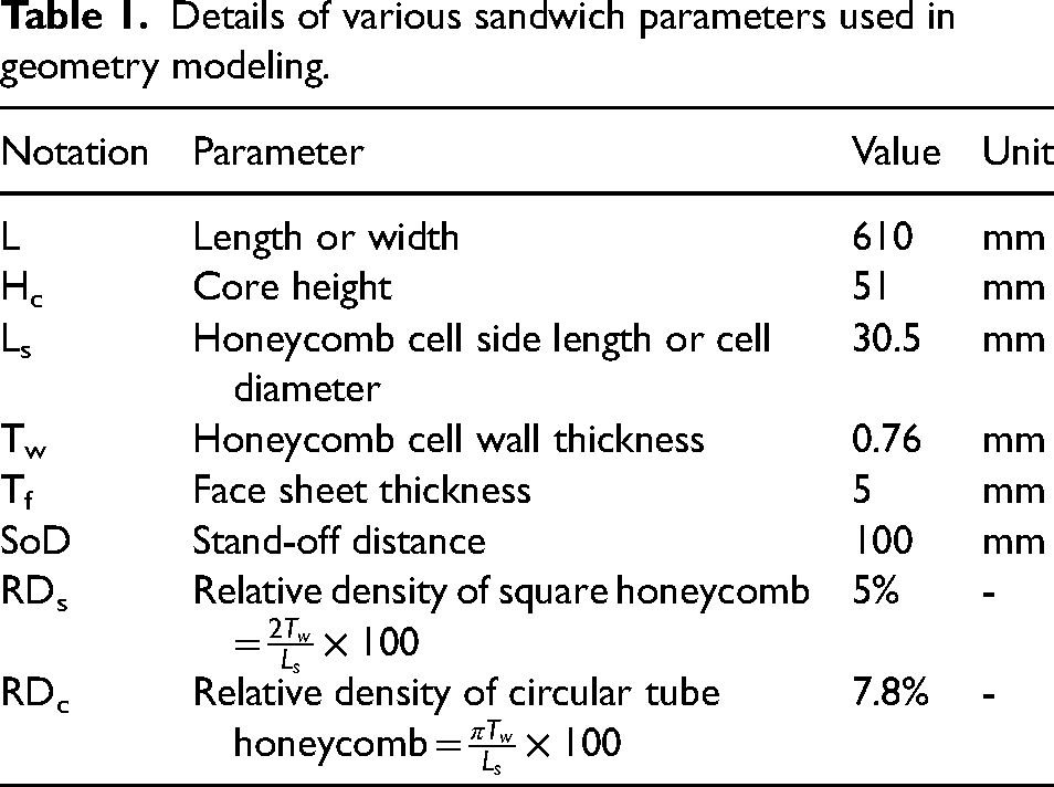
Similar to SHSP, a circular tube honeycomb sandwich panel (CTHSP) was modeled to compare the blast performance of the square and circular tube honeycombs. To determine the influence of foam-filled stiffened honeycombs on the blast behavior, a foam-filled SHSP (FFSHSP), and a foam-filled CTHSP (FFCTHSP) were modeled. To analyze the effect of the circular tube stiffener on the SHSP blast performance, a circular tube-filled SHSP (CTFSHSP) was modeled. All these sandwich panels’ isometric views with unit cell details are shown in Figure 3. The total volume occupied by these quarter sandwich models is kept constant at 305 mm × 305 mm × 61 mm. In all these quarter sandwich panels, contacting surfaces between the cores and face sheets were tied together with surface-to-surface contacts. The sandwich parameters of all these finite element quarter models are the same as those listed in Table 1. Based on the unit cell details, the relative densities of non-stiffened square and circular tube honeycomb cores are also mentioned in Table 1. Similar to SHSP, all other sandwich panels were also subjected to symmetry and ENCASTRE boundary conditions. The CONWEP air-blast loads of 1–3 kg of TNT were applied at a distance of 100 mm from the center of the top surface of the front face, as represented in Figure 2. The face sheets of these sandwich panels were discretized with 15 mm × 15 mm × 1 mm by assigning the C3D8R element type. The honeycombs were meshed with S4R elements of 1.5 mm × 1.5 mm. The used crushable Al foam was discretized with a 5 mm global mesh size of C3D8R elements. All these mesh sizes were chosen after mesh sensitivity analysis.
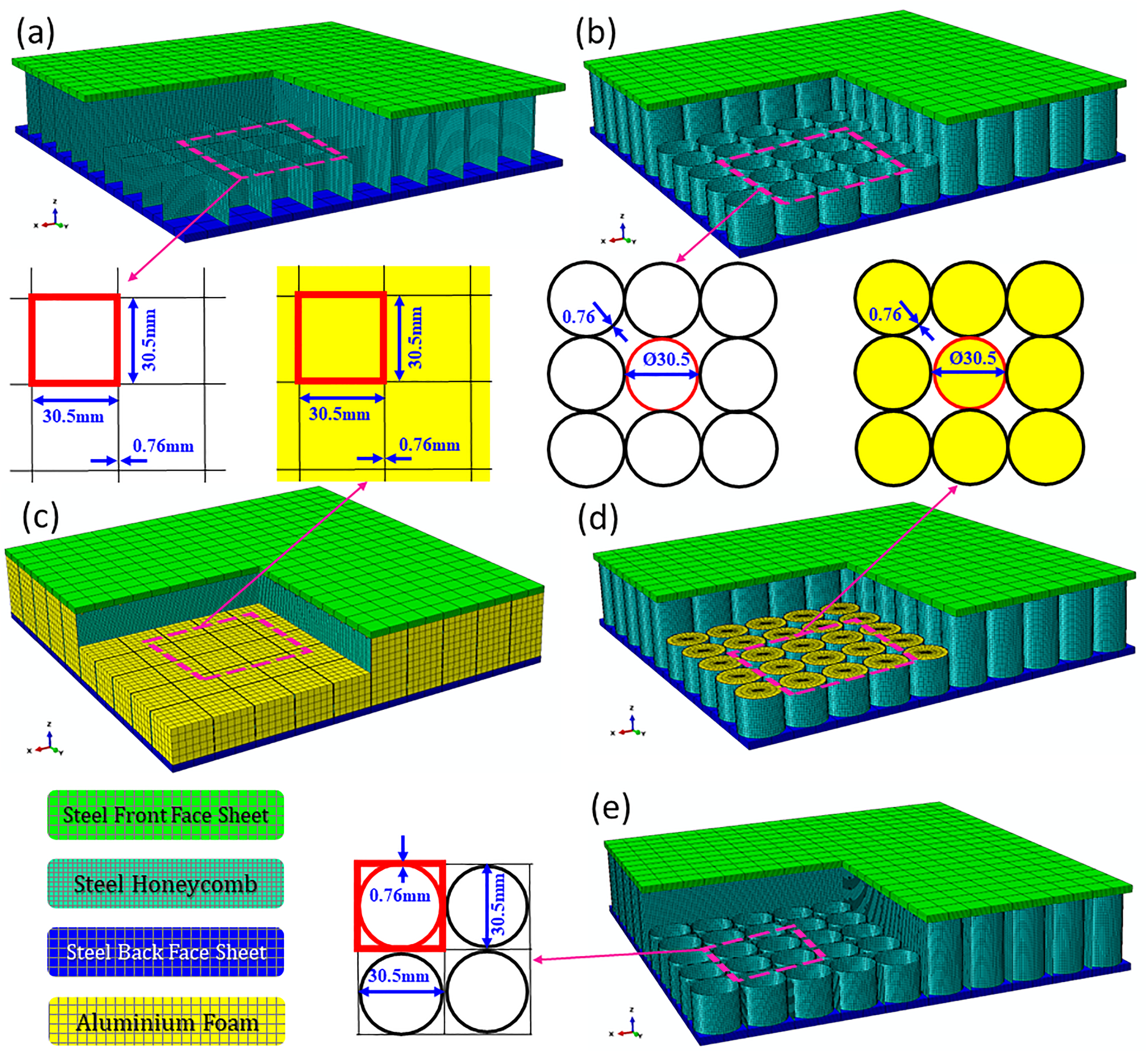
Quarter sandwich panel model with unit cell details of (a) square honeycomb sandwich panel (SHSP), (b) circular tube honeycomb sandwich panel (CTHSP), (c) foam-filled square honeycomb sandwich panel (FFSHSP), (d) foam-filled circular tube honeycomb sandwich panel (FFCTHSP), and (e) circular tube-filled square honeycomb sandwich panel (CTFSHSP).
Due to the use of stiffened honeycombs and the same honeycomb cell wall thickness, the masses of various sandwich panels are not equal. For the SHSP, CTHSP, FFSHSP, FFCTHSP, and CTFSHSP quarter model, masses are recorded as 8.97 kg, 10.2 kg, 12.1 kg, 12.6 kg, and 11.9 kg, respectively. The CTFSHSP is a combination of both square and circular tube honeycombs, but this model is only marginally heavier than the SHSP and CTHSP models. This is because most of the mass is concentrated in the face sheets.
Material properties and modeling
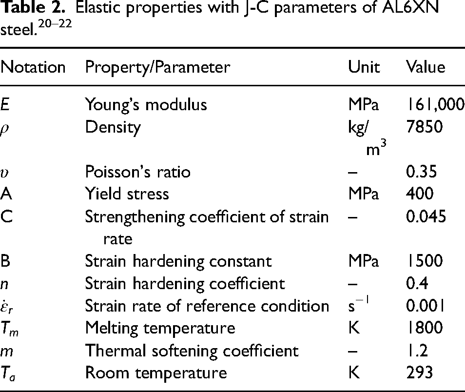
The face sheets and honeycomb cores of the sandwich models described in geometry modeling, interaction, loading, and meshing section were made of high-strength AL6XN steel. Dharmasena et al. 5 have also used the same material for the fabrication and testing of SHSP. The Johnson–Cook (J-C) material model was used for the assessment of the plastic deformation behavior of the face sheets and honeycomb cores. The J-C material model is a widely used empirical model for predicting the behavior of materials under high strain-rate loading conditions, such as in impact, blast, or ballistic events. 18 The J-C model is founded on the presumption that the material behavior under high strain-rate loading circumstances can be separated into four distinct stages: elastic, yielding, strain hardening, and failure. The model uses a combination of empirical relationships and physical principles to describe the behavior of the material in each stage. 15
The J-C model includes several parameters that are determined through experimental testing. These parameters can be used to predict material behavior under different loading conditions, including temperature and strain rate. The J-C model has been used in a variety of engineering applications due to its very good accuracy of results.
17
However, this material model is the best choice for the present work. Equation (3) provides the fundamental equation for this model19,20: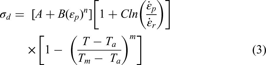
The used Al foam was subjected to significant compressive deformation under blast wave pressure. However, the volumetric hardening model of the crushable foam model was preferred for using Al foam. It accounts for the consequences of material crushing and plastic deformation on the material's behavior. During the deformation, compression hydrostatic stress changes and tensile hydrostatic stress remains constant. The shape of the yield surface (
Crushable Al foam elastic properties and parameters. 24
Hardening curve data for crushable Al foam. 24

Validation study
To verify the applicability of the following numerical approach, the front face sheet peak deflections, incident over pressures, and deformation patterns at 1–3 kg of TNT CONWEP air-blast for 0.1 m SoD on the SHSP model are compared with the literature 5 data for the same sandwich panel. These comparisons are shown in Figure 4. Figure 4(a) and (b) shows that the current numerical study produced very close results for the front face sheet peak deflections and incident overpressures when compared to the experimental results for the SHSP model. The peak deflection of the front face doesn’t exactly match the experimental results of 3 kg TNT blast. This could be due to the unavailability of the damage parameters for the AL6XN material in the literature. But the 3 kg numerical results are still useful for the purposes of comparing different sandwich configurations. The deformation patterns obtained by the numerical study are also very similar to the experimentally deformed structures, which can be seen in Figure 4(c). Therefore, the numerical approach followed for the SHSP model is verified and can also be applied to the other sandwich models.
Validation of (a) front face peak deflection, (b) peak overpressure, and (c) deformation patterns.
Results and discussion
Effect on pressure variation
The variation of incident overpressure on the top surface of the front face of the SHSP at all applied blast loading conditions is represented in Figure 5. The pressure variations at the center of the sandwich panel with respect to time are shown in Figure 5(a). From Figure 5(a), it is noted that the shock wave reached the front face sheet around 14 µs after the explosion of TNT. For explosion of a high mass of charge, the traveling speed of the shock wave is high. Hence, at a 3 kg TNT explosion, the shock wave reached the front face faster than the shock waves generated at a 2 kg and 1 kg TNT explosion, respectively. The intensity of overpressure is also highest at 3 kg of TNT blast, followed by 2 kg and 1 kg of TNT blast. These differences in arrival durations of the shock wave and overpressures for different masses of TNT explosions are clearly indicated in Figure 5(a). From Figure 5(a), it is also noted that the decay duration and positive pressure zone are the smallest for the 1 kg TNT blast, followed by the 2 kg and 3 kg TNT blasts. The maximum decay duration observed was approximately 0.3 ms at a 3 kg TNT blast. This duration is approximately 0.26 ms and 0.2 ms for 2 kg and 1 kg TNT blasts at 100 mm SoD, respectively. However, the specific impulse imparted to the target at a 1 kg TNT blast is the smallest, followed by those at 2 kg and 3 kg TNT.
(a) Pressure variation at center point, (b) distribution of peak overpressure in radial direction, and (c) patterns of pressure variation in top surface.
Due to the explosion of TNT, a spherical shock wave was generated and propagated with a very high velocity. The maximum overpressure experienced by the various nodal points in the radial direction from the center of SHSP is plotted in Figure 5(b). It indicates that the pressure is high at the center point and radially decreases at all blast loadings. This could be due to the spherical shock wave first interacting with the center of the front face according to the loading condition shown in Figure 2.
Figure 5(c) illustrates the pressure changes on the top surface with respect to time. From Figure 5(c), it is clearly observed that the pressure propagates radially outward on the surface from the center during the positive pressure zone, and after that, the pressure propagation is reversed. The intensity of overpressure at any particular point of the top surface suddenly experienced high pressure initially, thereafter, decreasing continuously with respect to time. For the same time interval, the overpressure propagation on the surface is higher for a high mass of TNT blast, and it can be clearly seen in Figure 5(c).
Effect on kinetic energy
When the spherically propagated shock wave interacts with the front face, it suddenly provides kinetic energy to the front face. After that, the front face travels with a high velocity, and this velocity is decelerated by the core buckle. After this stage, the core started to move in an out-of-plane direction and also imparted kinetic energy to the back face. However, in the air-blast loading, the front face of the sandwich panel gets kinetic energy first, followed by the core and back face. This phenomenon can be clearly revealed in Figure 6. The front face gained the most kinetic energy, followed by the back face and core. The core is crushed easily during blast loading. Hence, its kinetic energy is the smallest.
Kinetic energy distribution in various components of sandwich panel under air-blasts.
The variations of the whole model kinetic energy with respect to time for all modeled sandwich configurations under all applied blast conditions are demonstrated in Figure 7. Figure 7(a)–(c) represents the kinetic energy variation at 1, 2, and 3 kg of TNT CONWEP air-blasts, respectively, for the SHSP, CTHSP, FFSHSP, FFCTHSP, and CTFSHSP configurations. From Figure 7, it is noted that the maximum kinetic energy obtained by all FE-modeled sandwich configurations is near 0.15 ms, 0.2 ms, and 0.23 ms at 1 kg, 2 kg, and 3 kg TNT air-blasts, respectively. It can also be observed that the kinetic energy of all sandwich configuration rises as the mass of TNT increases from 1 kg to 3 kg. This delay in obtaining maximum kinetic energy and increase in kinetic energy of all sandwich configurations as increases in the mass of TNT for blast loads are due to the intensity of impulse applied on the target surface of sandwich configurations being proportional to the mass of explosive used. However, at the high-intensity blast loads, the sandwich configurations travel in an out-of-plane direction for a long time. Figures 6 and 7 show that at applied blast loads, all sandwich configurations as well as its components’ kinetic energy diminished around zero near the 0.6-ms mark. But, due to the good stiffness of all sandwich configurations, they again obtained some velocity and showed the spring-back effect. After 1 ms, the kinetic energy of all sandwich structures is approximately zero. Hence, it may be considered that the modeled sandwich structure gets permanent deformation within 1.5 ms. Therefore, the back face deflection data obtained at 1.5 ms for the SHSP was used for validation purposes in Validation study. From Figure 7, it is noted that the maximum kinetic energy of the SHSP is the highest, followed by the CTHSP, FFSHSP, FFCTHSP, and CTFSHSP at all air-blast loads. These results depict the CTFSHSP as having the highest robustness, followed by the FFCTHSP, FFSHSP, CTHSP, and SHSP. Figure 7 depicts the circular-tube honeycomb core as resisting the movement of the sandwich panel higher than the square honeycomb core. A further resistance in the movement was observed due to the use of the foam-stiffened honeycombs. The square honeycomb stiffened with circular tubes core highly resists the motion of sandwich panel under blasts.
Changes in kinetic energy of various sandwich panels under (a) 1 kg, (b) 2 kg, and (c) 3 kg of TNT air-blast.
Effect on face deflection
Figure 8(a) and (b), respectively, depicts the center point deflections of the front sheet and back sheet with regard to time for all sandwich configurations subjected to all blast loadings. Figure 8(a) shows that the SHSP front face center deflected higher than the other modeled sandwich panels at all air-blast loads for every instant of time. Similarly, the face center deflection of the back sheet is also observed to be highest for the SHSP in Figure 8(b). These highly deflected face centers of the SHSP represent its inferior blast mitigation characteristics. The center point deflections of both the front sheet and the back sheet of the CTFSHSP are the smallest at all blast loads for every instant of time, followed by the FFCTHSP, FFSHSP, CTHSP, and SHSP. Hence, the blast resistance in terms of the center point faces deflection decreases in this order. From effect on kinetic energy, it is observed that the kinetic energy of all sandwich configurations is approximately zero near the time of 1.5 ms, which represents the modeled sandwich panels being permanently deformed after this duration. Therefore, the radial deflection of both the front and back faces of the various sandwich configurations was recorded at 1.5 ms of simulation time. Figures 9(a), 10(a), and 11(a) illustrate the front face sheet deflection from the center point to a radially outward direction at 1 kg, 2 kg, and 3 kg of TNT blast in air, respectively. Similarly, Figures 9(b), 10(b), and 11(b) illustrate the back face sheet radial deflection at 1, 2, and 3 kg of TNT blast, respectively. The blast wave propagates spherically in air and radially in the sandwich panel's top surface, as discussed and observed in effect on pressure variation. It is also observed that its intensity decreases with respect to time as well as radial distance. Hence, both the front and back faces are deflected higher in the central region, and their deflection decreases gradually from the center to the clamped edges, as can be clearly observed from Figures 9–11. From Figures 8–11, it is discovered that the center point deflection and radial deflection of the front face are greater than the center point deflection and radial deflection of the back face of a sandwich panel. This happens due to the maximum amount of blast energy consumed during front face deflection and core crushing. Hence, only a small amount of the blast energy reaches the back face.
Center point deflection of sandwich panels’ (a) front face and (b) back face.
Radial deflection of sandwich panels’ (a) front face and (b) back face at 1 kg TNT blast.
Radial deflection of sandwich panels’ (a) front face and (b) back face at 2 kg TNT blast.
Radial deflection of sandwich panels’ (a) front face and (b) back face at 3 kg TNT blast.
From Figures 9(a), 10(a), and 11(a), it is noted that the radial front face deflection of the SHSP is the highest among all sandwich configurations and at all blast loadings. Similarly, from Figures 9(b), 10(b), and 11(b), it is also found that the radial face deflection of the SHSP back face is the highest among all sandwich configurations and at all blast loadings. These results indicate the SHSP has the lowest face sheet deformation resistance in comparison to all other sandwich models. From the comparison face deflection of empty honeycomb sandwich panels, it is noted that the CTHSP shows smaller radial deflection of both the front and back face sheets in comparison with the SHSP. This is due to the circular tube honeycomb core having a higher buckling resistance and provides stronger structural support to the front face than the square honeycomb cells with the same wall thickness under all blast loadings. From the comparison of radial face deflection of the foam-stiffened honeycomb sandwiches, it is also observed that the foam-stiffened circular tube honeycomb imparts higher resistance to face deflection than the foam-stiffened square honeycomb. From the comparison of honeycomb sandwiches with and without foam stiffening, it is noted that the FFSHSP provides smaller radial face deflection for both the front and back faces than the SHSP. Similarly, the FFCTHSP imparts higher resistance to face deflection than the CTHSP. This indicates that the foam-stiffened honeycomb core improves the deformation resistance of the sandwich panel under blast loads as compared to the empty or unstiffened honeycomb core used in sandwich panels. The circular tube honeycomb core has higher deformation resistance characteristics than the square honeycomb core under blast loadings, for both with and without foam stiffening cases. From Figures 9–11, it is analyzed that the circular tube-stiffened square honeycomb cells provide the smallest radial face deflection in comparison to the with or without foam-stiffened honeycomb sandwich panels. The percentage reduction in both front and back face sheet peak deflection and percentage increase in mass of all modeled sandwiches with respect to SHSP is catalogued in Table 5.
Percentage decrement in peak deflection of face sheets and percentage increment in mass of the panel in comparison with SHSP.
From Figures 8–11 and Table 5, it can be seen that the CTFSHSP provides a 14–50% reduction in face deflections as compared to the SHSP with an increase in 32.7% mass. Similarly, the CTHSP, FFSHSP, and FFCTHSP reduced the face deflection by 5–30%, 9–31%, and 11–37%, respectively, in comparison to the SHSP. These results indicate that the CTFSHSP has the highest face deflection resistance under all applied blast loads, followed by the FFCTHSP, FFSHSP, CTHSP, and SHSP. The CTFSHSP is lighter than the FFSHSP and FFCTHSP, which means that the use of the circular tube-strengthened honeycomb sandwich is more beneficial than the foam-strengthened honeycomb sandwiches.
Effect on energy absorption
The internal energy of various designed sandwiches with respect to time for all applied blast loads is plotted in Figure 12. It is the sum of the energy absorption of the sandwich panel due to plastic deformation (PDE), energy absorption due to elasticity (strain energy), and artificial strain energy due to the usage of reduced integration. From Figure 12, it is observed that the SHSP has the highest internal energy, followed by the CTHSP, FFSHSP, FFCTHSP, and CTFSHSP for a fixed mass of TNT explosion. The internal energy absorption obtained in this order due to the damage of sandwich models in air-blasts decreases in this order. Figure 12 also depicts that the internal energy of all sandwich panels increases with an increase in explosive charge. This could be due to the sandwich panels’ elastic limit being crossed and more plastic deformation occurring due to the high intensity of the TNT blast. Due to the smaller internal energy of the CTFSHSP as compared to the other sandwich model, it proves the most robustness for blast loadings. The obtained patterns of time-dependent energy absorption of the sandwich models prove that the circular tube stiffening is more beneficial than the foam-filling stiffening of honeycombs.
Sandwich plates’ capacity to absorb energy when subjected to air-blasts.
The large plastic deformation of the sandwich components is the main failure criterion against blast loads. Therefore, the PDE of each component of each sandwich panel at all applied blast loads is shown in Figure 13(a). Each bar of Figure 13(a) represents the total PDE of a sandwich model. The percentage contribution of sandwich components to the energy dissipation during plastic deformation is illustrated in Figure 13(b).
(a) Plastic dissipation energy (PDE) by components of modeled sandwich panels and (b) sandwich panel components’ percentage contribution in PDE under blast loads.
From Figure 13(a), it is noted that the PDE by front sheet of the FFCTHSP is the smallest, followed by the CTFSHSP, FFSHSP, CTHSP, and SHSP at all blast loading conditions. This could be due to the core of the FFCTHSP providing the strongest structural support to the front face, followed by the CTFSHSP, FFSHSP, CTHSP, and SHSP. From the comparison of the back face PDE, it is noted that the back face PDE of the CTFSHSP is the smallest among all modeled sandwich panels, followed by the FFCTHSP, FFSHSP, CTHSP, and SHSP. These results depict that the core of the CTFSHSP transferred the smallest amount of blast energy to the back face, followed by the FFCTHSP, FFSHSP, CTHSP, and SHSP's cores. The PDE of cores is also found in the same order as observed for the back face sheet. This happens because the core crushing decreases in the order of SHSP, CTHSP, FFSHSP, CTFSHSP, and CTFSHSP. When the blast load increases from 1 kg to 3 kg of TNT, the PDE of each sandwich component as well as the whole sandwich model increases due to the overpressure imparted to the sandwich panels increased with an increase in TNT mass, which results in large plastic deformation.
Figure 13(b) shows that the core of a sandwich panel gives the maximum percentage contribution to energy absorption, followed by the front face and back face. This percentage contribution of the sandwich panel's core decreases with an increase in the mass of TNT for blast loads. This is due to the fact that both face sheets’ deformation increases with respect to the mass of TNT used for the blast. As a result, the face sheet's percentage contribution to energy absorption increased while the core's percentage contribution decreased, causing the explosive charge to increase. From Figure 16(b), it is also observed that the core of the CTHSP percentage contribution in the PDE is higher than the core of the SHSP. This result indicates that the circular tube honeycomb is a more significant option for designing a blast-resistant structure. The foam stiffening of the square and circular tube honeycombs improves the percentage contribution in PDE of the core structure. Hence, the cores of FFSHSP and FFCTHSP contribute a higher percentage to PDE than the SHSP and CTHSP. The use of a circular tube stiffened square honeycomb also enhanced the core contribution to PDE in comparison with the unstiffened cores.
Equivalent plastic strain (PEEQ) of the various cores at all applied blasts.
Effect on deformation modes and core crushing
The permanently deformed sandwich panels’ crushing behavior under blast loads is divided into three distinct deformation zones: the fully crushing zone, the partially crushing zone, and the small buckling zone. These deformation zones are based on patterns of honeycomb cell wall folding and the out-of-plane deformation of face sheets. These deformation zones are indicated in Figure 14. In the fully crushing zone, the cell walls of honeycombs are fully folded, the foam is highly densified, and the face sheets are highly stretched with high out-of-plane bending. In the partially crushing zone, the cells of honeycombs are partially folded or buckled, the foam is partially densified, and the face sheets are deflected transversely less than in the fully crushing zone. In the small buckling zone, both core and face sheet deformations are very small. The fully crushing zone and small buckling zone are located in the central region and outermost region of the sandwich panel, respectively. The partially buckling zone was obtained in the intermediate region of the sandwich panel. If the intensity of the blast loads is small, then the fully crushing zone may not appear in the sandwich panel.
Various deformation zones of a sandwich panel under air-blast loads.
The permanently deformed modeled sandwich panels at all applied blast loadings are illustrated in Figure 15. From Figure 15, for 1 kg of TNT blast load, it is noted that the all-deformed sandwich panels have only partially crushing zones and small buckling zones are available and fully crushing zone may be negligible. This result indicates that the all-modeled sandwich panels have the capability to withstand the intensity of a blast load of 1 kg TNT. When the charge of the explosive increases from 1 kg to 2 kg, the considerably fully crushed zones appear in the SHSP model only. Other sandwich panel panels still have only partially crushing zone and small buckling zones. The partially crushing zone of the CTHSP is greater than the FFSHSP, FFCTHSP, and CTFSHSP partially crushing zones. This result indicates that the SHSP has the poorest blast resistance, followed by the CTHSP. The partially crushing zone of all sandwich panels is increased for the 2 kg of TNT blast as compared to the partially crushing zone that appeared in the 1 kg of TNT blast. This happens because the intensity of the impulse transfer to the sandwich panel is proportional to the mass of the explosive used. At a 3 kg TNT blast, both the SHSP and CTHSP have a large fully crushing zone and a partially crushing zone. The small buckling zone of these two sandwich models is negligible. These deformed structures of the SHSP and CTHSP show that they are not capable of sustaining the blast load of 3 kg of TNT. The fully crushing zone is absent in the FFSHSP, FFCTHSP, and CTFSHSP at all applied blast loads due to their good blast resistance characteristics. These three sandwich panels still have the capability to sustain more than a 3 kg TNT blast for a 100 SoD.
Plastically deformed sandwich panels under air-blast loadings.
It is evident from Figure 15 that, under all applied blast pressures, the CTFSHSP cores are crushed more lightly than those of the other sandwich panel. This demonstrates that among all sandwich panels, the CTFSHSP has the greatest blast protection. The honeycomb core's crushing strength is increased by the foam filling. The FFSHSP and FFCTHSP cores are, therefore, crushed less than the SHSP and CTHSP. The resulting deformed structure also demonstrated that the circular tube honeycomb exhibits higher features of buckling strength than the square honeycomb. Because the core crushing of FFCTHSP is obtained smaller than that of the FFSHSP, and the core crushing of CTHSP is obtained smaller than that of the SHSP. Therefore, the circular tube stiffened square honeycomb greatly improves the deformation resistance under blast loads. The circular tube stiffening is more significant than the foam filling in terms of the deformation resistance of the sandwich panel.
PEEQ (equivalent plastic strain) is a key variable for the measurement of plastic deformation that the modeled sandwich panels undergo during the blast loadings. It is calculated using the following equation (9)
25
: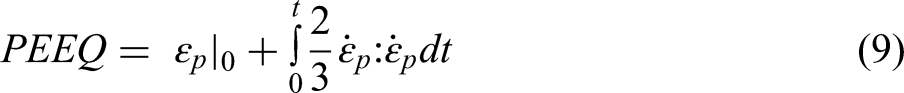
When the PEEQ value is greater than zero for an element, it indicates that the material has undergone plastic deformation. Various sandwich panel core PEEQ values visualized from contour plots in ABAQUS are drawn in Figure 16 to identify areas of high plastic deformation and potential failure. From Figure 16, it is noticed that the PEEQ maximum value is the highest for the SHSP model, followed by CTHSP, FFSHSP, FFCTHSP, and CTFSHSP for a particular mass of TNT blast. Hence, the resistance to plastic deformation of the sandwich model under blast loads increasing this order of the modeled sandwiches. The foam filling in the honeycombs helps to distribute the blast pressure uniformly on the core structure. Hence, the globally plastic strain appeared on the cores of FFSHSP and FFCTHSP as compared to SHSP and CTHSP. The empty honeycombs show a highly localized plastic strain near the central region. The CTFSHSP also shows globalized deformation with less core crushing. Hence, its maximum PEEQ value is the smallest at all blast loads as compared to the other sandwich model cores.
The back face of any sandwich panel acts as a final protection against blast attacks, and the back face center deflection, back face radial deflection, and back face PDE of the CTFSHSP are the smallest among all sandwich configurations. Hence, the CTFSHSP is the best protective structure against blast loads. Due to changes in core topology as well as the usage of foam and circular tube stiffeners, the masses of the modeled sandwich panels are not equal. From the comparison of the masses of the sandwich panels, it is found that the CTFSHSP is 5.56% and 1.65% lighter than the FFCTHSP and FFSHSP, respectively. This result also indicates that the circular tube stiffened honeycomb improves the sandwich's blast resistance with little increase in mass. The foam-stiffened honeycombs increase the blast resistance of sandwich panels with a highly increased mass. Many researchers are trying to improve the blast performance of sandwich panels by using foam stiffening. But this study found that the circular tube stiffening provided higher blast mitigation than the foam stiffening. Hence, the CTFSHSP is the lightweight stiffened sandwich panel having the highest blast mitigation characteristics in terms of the smallest radial as well as center face deflection, the smallest core crushing, and the lowest PDE. Due to this significant improvement in blast resistance, the CTFSHSP sandwich configuration can be used in the automobile sector for making vehicle armor and protective panels. In the aerospace industry, blast-resistant CTFSHSP sandwich configuration is used in the design of aircraft and spacecraft. In the marine sector, it can be used in the construction of naval vessels, including warships and submarines. In the railway sector, the CTFSHSP sandwich configuration can be used in the construction of train carriages, particularly for applications where trains pass through areas of high risk. These structures can also be used in the construction of railway bridges and tunnels to protect against terrorist attacks or natural disasters.
Conclusions
This dynamic explicit analysis characterized the dynamic behavior of various stiffened and unstiffened sandwich panels under CONWEP air-blast loadings. The key conclusions from this numerical study are as follows:
In the instance of sandwich panels made of unstiffened honeycomb, circular tube honeycomb offers significantly greater blast protection than square honeycomb. The foam-filled tubular honeycomb had better explosion mitigation properties for the instance of sandwich panels with foam-stiffened honeycomb. The foam-stiffened honeycomb cores improved the blast mitigation of the sandwich panel. The circular tube stiffener improved the blast resistance of the honeycomb sandwich panel more than the foam stiffener and also reduced the mass of the sandwich panel. The kinetic energy, face radial deflections, face center deflections, core densification, PEEQ of the core, PDE, and internal energy of the lightweight CTFSHSP were the smallest, followed by the FFCTHSP, FFSHSP, CTHSP, and SHSP. Hence, the circular tube stiffened honeycomb is more beneficial than the foam-stiffened honeycombs. The peak overpressure, decay time duration, kinetic energy of sandwich panel, center point face deflection, radial face deflection, PDE by sandwich, face sheet contribution to PDE, internal energy of sandwich panels, core densification with cell wall buckling, and lateral bending of face sheets were increased with an increase in explosive mass for blast. But, blast wave arrival duration and core contribution to PDE decreased with an increase in explosive mass for the blast. The circular tube stiffened SHSP provides optimum blast resistance performance and is preferred to be used for armored vehicles and naval ships to make them blast proof.
Footnotes
Declaration of conflicting interests
The author(s) declared no potential conflicts of interest with respect to the research, authorship, and/or publication of this article.
Funding
The author(s) received no financial support for the research, authorship, and/or publication of this article.