
Abstract
Lightweight fibre-reinforced thermoplastic (FRTP) driveshafts are ideal for automotive applications. In this work, material and buckling failures of FRTP driveshafts subjected to torsion at elevated temperature are analysed by finite element modelling. Critical speed at increasing temperature is also quantified. The driveshafts comprise unidirectional carbon/polyetheretherketone (PEEK) layers with/without an inner layer of aluminium or unreinforced plastic. Temperature-dependent material properties are considered. The results demonstrate achievable performance of the fully carbon/PEEK and hybrid driveshafts, which are compared with traditional alloy counterparts. The carbon/PEEK shaft exhibits marked temperature sensitivity but satisfies the design requirements at high temperature with significant weight reduction. A hybrid shaft composed of carbon/PEEK layers over-wrapped onto an aluminium tube provides a compromise in terms of superior buckling resistance and critical speed but reduced material failure safety factor. Utilising a thick layer of unreinforced plastic to reduce fibre volume may only be suitable for low-temperature, low-speed applications.
Introduction
Fibre-reinforced composite materials are widely used in aerospace and automotive sectors where their desirable attributes, including high specific strengths and moduli and excellent corrosion resistance, are extremely useful. Cylindrical driveshafts for power transmission are an application in which composites are serving as lightweight alternatives to traditional metallic counterparts. Composite driveshafts are made up of multiple unidirectional fibre-reinforced layers wound at prescribed angles. Elastic constants and layup are tailored to meet the overall design requirements, namely sufficient load carrying capacity, buckling torque and critical speed. 1
The behaviour of composite driveshafts has been studied for many years with much of the focus on fibre-reinforced thermoset (FRTS) materials, typically epoxy-based. Shokrieh et al. 2 analysed the buckling torque of carbon/epoxy driveshafts by finite element (FE) modelling. They employed linear layered shell elements and achieved better agreement with experimental data than the closed form solutions presented by Bauchau et al. 3 and Bert and Kim 4 for most configurations examined. Lee et al. 5 experimentally assessed the torsion capacity of a hybrid driveshaft consisting of carbon/epoxy layer co-cured on the inside of an aluminium tube. They reported a 75% mass reduction and 160% increase in torque capacity compared to a steel part. Mutasher et al. 6 tested a driveshaft with fibre-reinforced layers wound onto the outside of an aluminium tube, again showing the performance benefits of a hybrid design. Mutasher 7 later predicted torsional strength by finite element analysis (FEA). Badie et al. 1 studied the effects of fibre angle and layup on torsional stiffness, natural frequency, buckling, fatigue and failure modes of hybrid carbon-glass/epoxy driveshafts. Experimental results showed a reduction in stiffness of the hybrid specimens compared to carbon-only. The experiments of Tariq et al. 8 revealed the same for carbon-glass and carbon-aramid shafts. Sevkat and Tumer 9 investigated residual torsional properties of E-glass/epoxy, carbon/epoxy and hybrid E-glass-carbon/epoxy shafts after impacts. Sevkat 10 subsequently showed how a functionally hybridised carbon-glass/epoxy shaft can be tailored to give near identical stress and strain responses to the carbon/epoxy counterpart under torsion. The ratio of carbon-to-glass volume was decreased from carbon-only for outermost layer based on linearly decreasing shear stress from outer to inner surface. Misri et al. 11 studied the behaviour of natural kenaf fibre-reinforced shafts under torsion by experiments and FEA with good agreement between methods. The inclusion of an aluminium layer enhanced torsional strength significantly. Filho et al. 12 performed torsion testing of a carbon/epoxy tube with [±45]5 layup. Maximum torque was over-predicted by classical lamination theory and under-predicted by FE modelling with Tsai-Wu failure evaluation. Gong et al. 13 performed static and dynamic analyses of a four-directional braided carbon/epoxy driveshaft and presented an optimal lightweight design.
Literature pertaining to combined torsion and thermal loading of composite cylinders is largely limited to buckling analyses. Li and Shen 14 employed third-order shear deformation theory for nonlinear analysis of braided carbon/epoxy shells under torsion in thermal environments. Lower buckling loads and post-buckling paths were observed when temperature-dependent material properties were accounted for. Higher-order analysis of nanocomposite cylinders has also been performed. 15 Manikandan et al. 16 simulated the buckling and post-buckling response of a cylindrical shell with [0/ ± 45/90]S lamination under torsion with temperature rise in the FE software, Abaqus. Thermomechanical coupling reduced the buckling load resistance substantially compared to uncoupled loading.
Fibre-reinforced thermoplastic (FRTP) composites can offer a number of in-service benefits over FRTS alternatives, including superior ductility, impact resistance and damage tolerance. FRTPs are processed with in situ consolidation, and additional curing is not required. Furthermore, thermoplastics can be melted down and recycled. In light of this, manufacturers have developed FRTP driveshafts in recent years. Given inherent concerns surrounding temperature stability, it is important to investigate the performance of FRTP driveshafts at the maximum service temperatures required for practical applications, taking into account the effects of temperature on material properties. A maximum service temperature of at least 120 °C is typically required for compact and medium-sized car driveshafts. 17 To the authors’ best knowledge, the torsional behaviour of an FRTP driveshaft at elevated temperature has not previously been examined and compared with traditional metallic counterparts considering temperature-dependent material properties in the literature.
In this paper, FE models are developed to analyse the material failure and buckling responses of a carbon/polyetheretherketone (PEEK) driveshaft under torsion combined with uniform temperature increase up to 125 °C. Reductions in critical speed at elevated temperature are also quantified. The results are compared with traditional aluminium and steel shafts to assess practical performance capabilities. In addition to the fully carbon fibre-reinforced plastic (CFRP) shaft, hybrid driveshafts composed of an aluminium tube over-wrapped with CFRP layers (not previously examined at high temperature) or unreinforced plastic tube over-wrapped with CFRP are also studied. The concept of replacing a portion of the CFRP laminate with a thick layer of unreinforced plastic could represent an economical means of lowering the total volume of carbon fibres without adding susceptibility to corrosion and does not appear to have been analysed before this paper. Temperature-dependent material properties are considered throughout the analyses.
Methodology
Driveshaft dimensions and materials
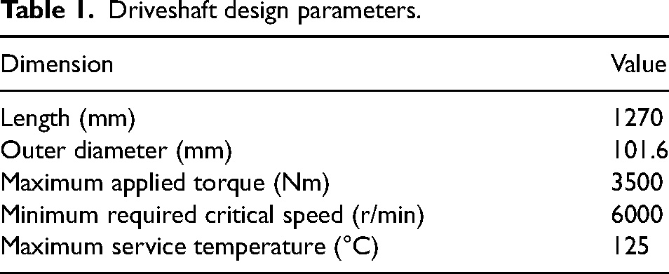
Generic design parameters, typical of available passenger car driveshafts, considered in the present investigation are given in Table 1. For the purpose of comparison, all shafts were considered to have the same outer diameter.
Driveshaft design parameters.
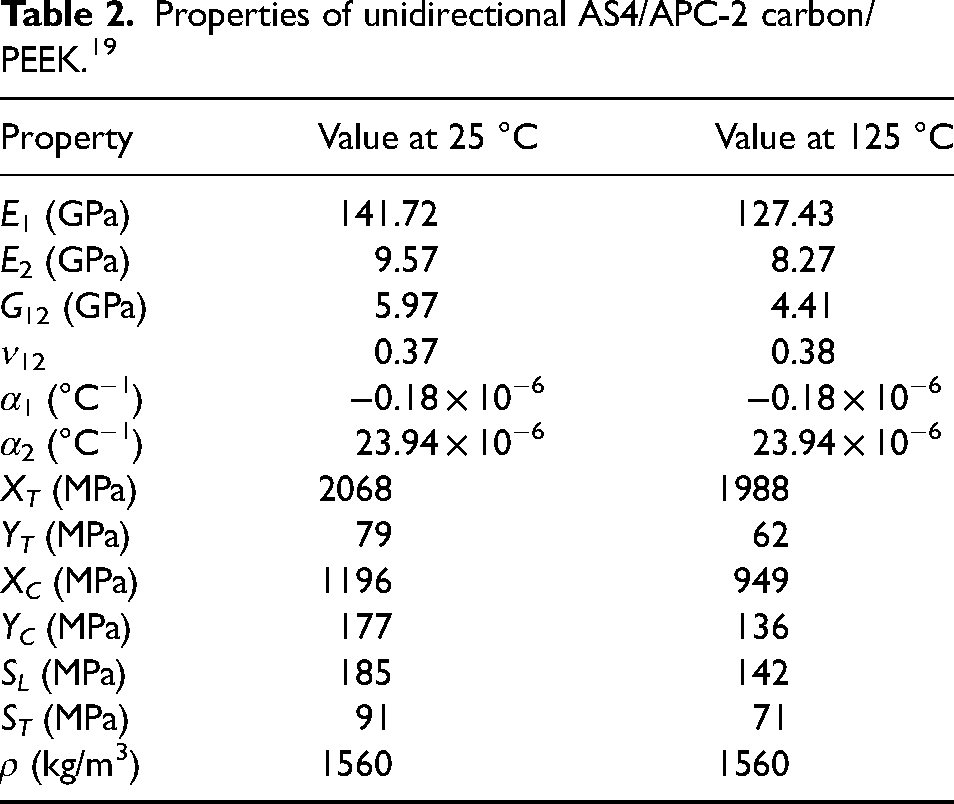
Carbon/PEEK AS4/APC-2 was selected for this work. APC-2 is semi-crystalline with a glass transition temperature of 143 °C and can be used up to 260 °C depending on stress conditions. 18 APC-2 composites display excellent toughness and resistance to damage and environmental conditions. Temperature-dependent properties for AS4/APC-2 are listed in Table 2, with the values at intermediate temperatures being linearly interpolated in this study. It was noted that α1 is a small, negative value, meaning the composite will contract in the fibre direction when heated. Negative coefficient of thermal expansion (CTE) is not often come across in materials science but is a known characteristic of carbon fibre. 20 The compositing of carbon fibres and polymer matrix can result in near-zero CTEs that can be exploited in applications involving tight tolerances.
Properties of unidirectional AS4/APC-2 carbon/PEEK. 19
A fibre winding angle of 45° from the shaft longitudinal axis is known to be optimal for torque loading capacity. 7 A carbon/PEEK shaft composed of 30 plies of equal thickness arranged in the angle-ply sequence [±45]15 was studied in this work. The total wall thickness was 3.75 mm and the mass of the driveshaft was 2.28 kg.
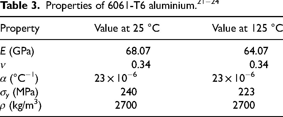
Typical aluminium (6061-T6) and steel (1045) driveshafts were chosen for comparison. The isotropic properties are listed in Tables 3 and 4. Thicknesses of the aluminium and steel driveshafts were 4.5 mm and 2.35 mm, respectively. These dimensions were chosen to give a material safety factor of approximately 2.5 under the maximum torque applied at 25 °C as a basis for comparison. The aluminium shaft weighed 4.71 kg and the steel shaft weighed 7.32 kg.

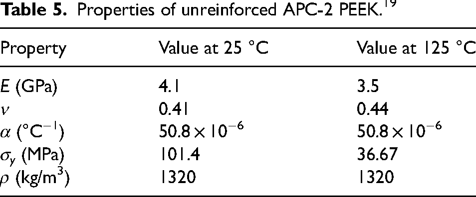
The hybrid shafts consisted of an inner tube of aluminium or unreinforced PEEK over-wrapped with perfectly bonded AS4/APC-2 layers. The carbon/PEEK-aluminium shaft comprised a 2 mm-thick aluminium (6061-T6) tube with 2 mm of carbon/PEEK laminate arranged in the sequence [±45]8. The total mass was 3.30 kg. The carbon/PEEK-PEEK shaft comprised 3 mm of unreinforced PEEK (properties in Table 5) with 3 mm of carbon/PEEK laminate arranged in [±45]12 and had the same total mass, 3.30 kg.
Properties of unreinforced APC-2 PEEK. 19
FE stress model
Stresses in the driveshafts under combined torsion and thermal load were analysed by FE modelling in the commercial package, Abaqus/CAE 2019. A predefined field was used to apply a uniform temperature profile following an initial (reference) temperature. Torque, T, was then applied to a reference point located at the centre of one end of the driveshaft with the end nodes constrained to the reference point via a kinematic coupling. The opposite end was fixed.
The model was meshed using element type S4R and a suitable mesh density was established by means of a convergence exercise. Convergence of maximum fibre and transverse stresses with increasing mesh refinement for the carbon/PEEK driveshaft is shown in Figure 1. The number of elements deemed suitable for the model in the present study is labelled on the plots. The differences between stresses for the selected mesh and the finest mesh are less than 0.05%. The final mesh contains 180,624 total elements.
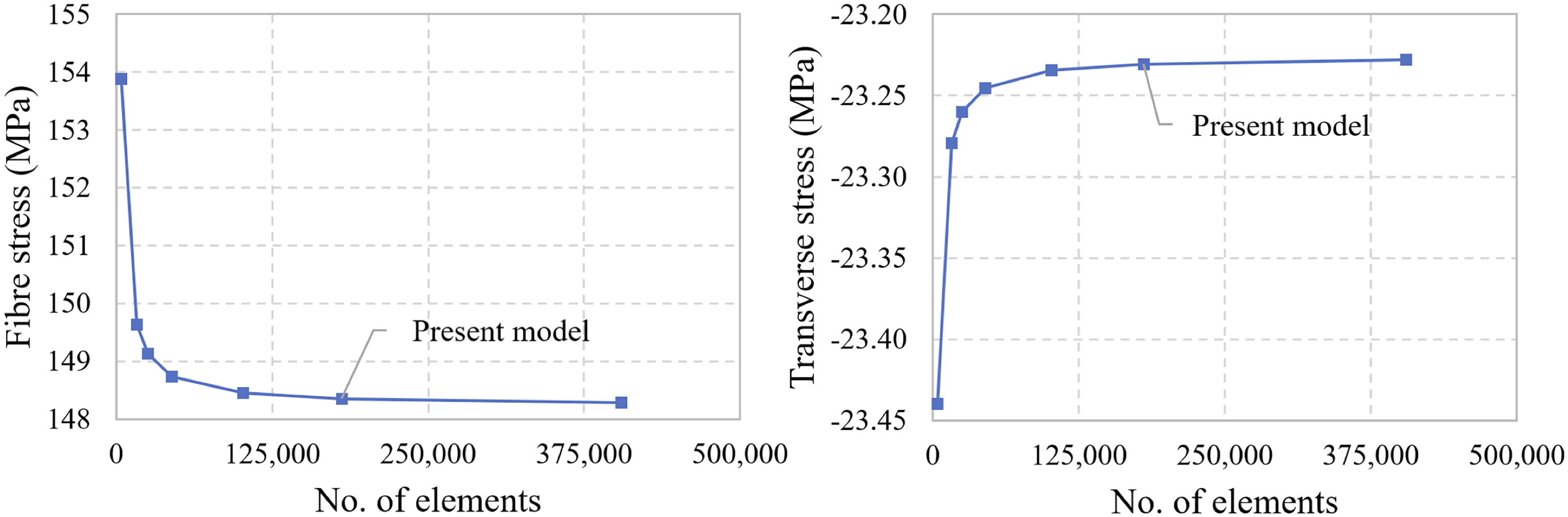
Carbon/PEEK driveshaft stresses versus mesh density: T = 3500 Nm at 125 °C.
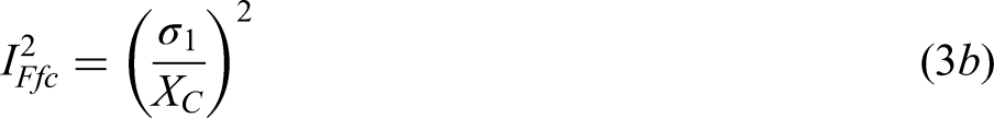
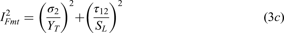
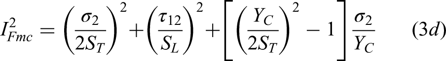
Stresses obtained from the FEA were used to determine material safety factors for the driveshafts. The factor for the carbon/PEEK material was taken as the more conservative value obtained using well-known Maximum Stress (herein ‘Max Stress’) and Hashin criteria. According to Max Stress, failure occurs when any stress along a principal material direction exceeds the corresponding allowable. The failure indices are written as: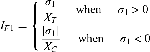
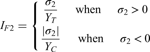
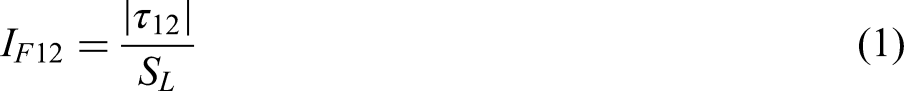
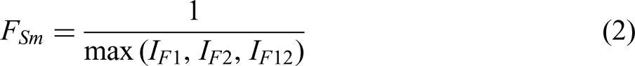
Fibre in tension (when σ1 > 0):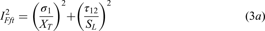


FE buckling model
The above model was adapted for the thermal-torsion buckling problem, which involved two parts. A linear eigenvalue analysis was first performed to estimate the critical buckling torque and mode shape. Eigenvalue analysis is expected to over-predict critical load as the structure is assumed to be geometrically perfect. A modified Riks (arc-length) analysis incorporating geometric imperfection of the initial two eigenmode shapes estimated from the linear analysis was then performed to determine the thermal-torsion buckling load. The Riks method solves simultaneously for loads and displacements and is suitable for unstable, nonlinear buckling problems. Uniform temperature was applied as a predefined field before the Riks step. Suitable mesh density for the buckling analysis was determined by convergence of linear buckling torque, shown in Figure 2. The critical value for the selected mesh containing 101,920 elements is within 0.05% of the finest mesh result.
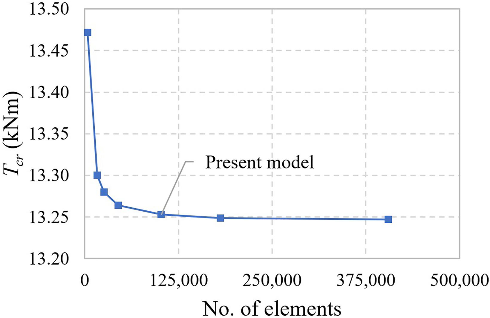
Carbon/PEEK driveshaft critical buckling torque versus mesh density.
The safety factor for buckling can be taken as the ratio of buckling torque to applied torque:

Critical speed calculation
Critical speed, corresponding to the lowest natural frequency of the driveshaft, must be safely above the maximum speed of rotation during operation to avoid large amplitude vibration (whirling). Lowest natural frequency is calculated as follows: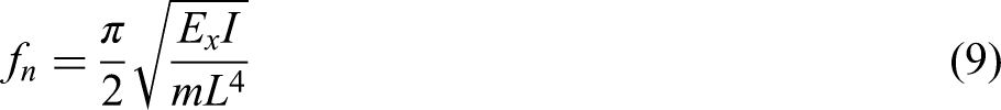
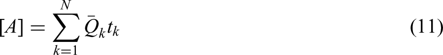
The average modulus of the composite shaft with a total of N layers is determined from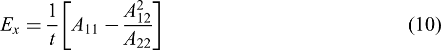

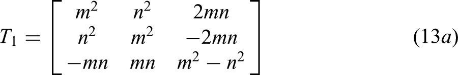
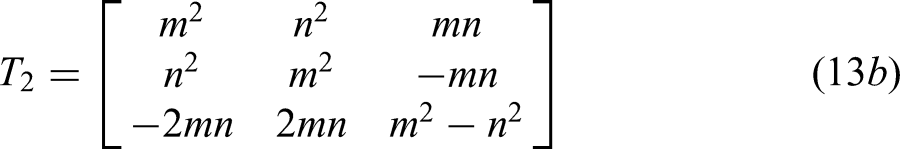
The Qij coefficients are determined from engineering constants as follows: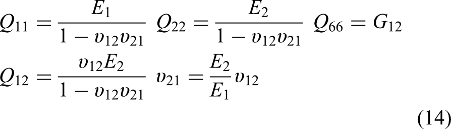

Results and discussion
Material failure
Material safety factors for carbon/PEEK, aluminium and steel driveshafts subjected to torque magnitude of 3500 Nm over the range 25 °C to 125 °C are shown in Figure 3. An initial temperature of 25 °C is assumed in all cases. Responses of aluminium and steel driveshafts (intentionally dimensioned to have safety factors of approximately 2.5 at 25 °C) do not vary significantly over the temperature range. At 125 °C, the factors are roughly 7% lower than at 25 °C. The carbon/PEEK response exhibits two distinct phases. Initially, from 25 °C to 65 °C, the dominant failure mechanism according to both Max Stress and Hashin is fibre compression and the safety factor does not change meaningfully. Above 65 °C, matrix compression overtakes fibre compression as the dominant mode according to Hashin. In other words, there is a switch from fibre to matrix strength governing the response at elevated temperature. This is accompanied by a more rapid decrease in safety factors with temperature. According to the less conservative Max Stress criterion, the switch from dominant fibre to transverse compression occurs above 85 °C. The shift to the matrix-dominated mode can be attributed to high sensitivity of the polymer to thermal load and larger CTE in the direction transverse to the fibres. Despite greater sensitivity, the carbon/PEEK shaft offers superior safety factor compared to alloy counterparts even at 125 °C.
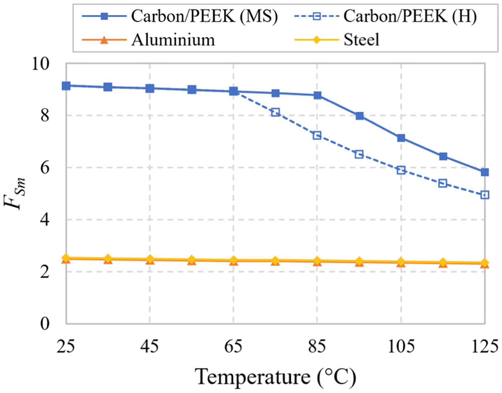
Variation of material safety factor with temperature for carbon/PEEK (based on Max Stress (MS) and Hashin (H)), aluminium and steel driveshafts.
Safety factors for the hybrid carbon/PEEK-aluminium driveshaft are shown in Figure 4. Max Stress and Hashin criteria are in agreement for the carbon/PEEK portion. With rising temperature, there is a stress redistribution that results in an increase in dominant fibre compression factor up to 45 °C, beyond which fibre tension becomes dominant in layers orientated with the reverse fibre angle and the factor decreases at higher temperatures. The aluminium layer is less temperature-sensitive but exhibits a significantly lower safety factor, that is, it is the critical layer dictating overall safety of the part. Yielding of the inner aluminium layer before cracking along the fibre direction and delamination has been observed experimentally for an FRTS-based hybrid shaft at room temperature. 6 Here, the safety factor at high temperature (1.85) is slightly lower than that of fully aluminium (2.32) and steel (2.35) shafts.
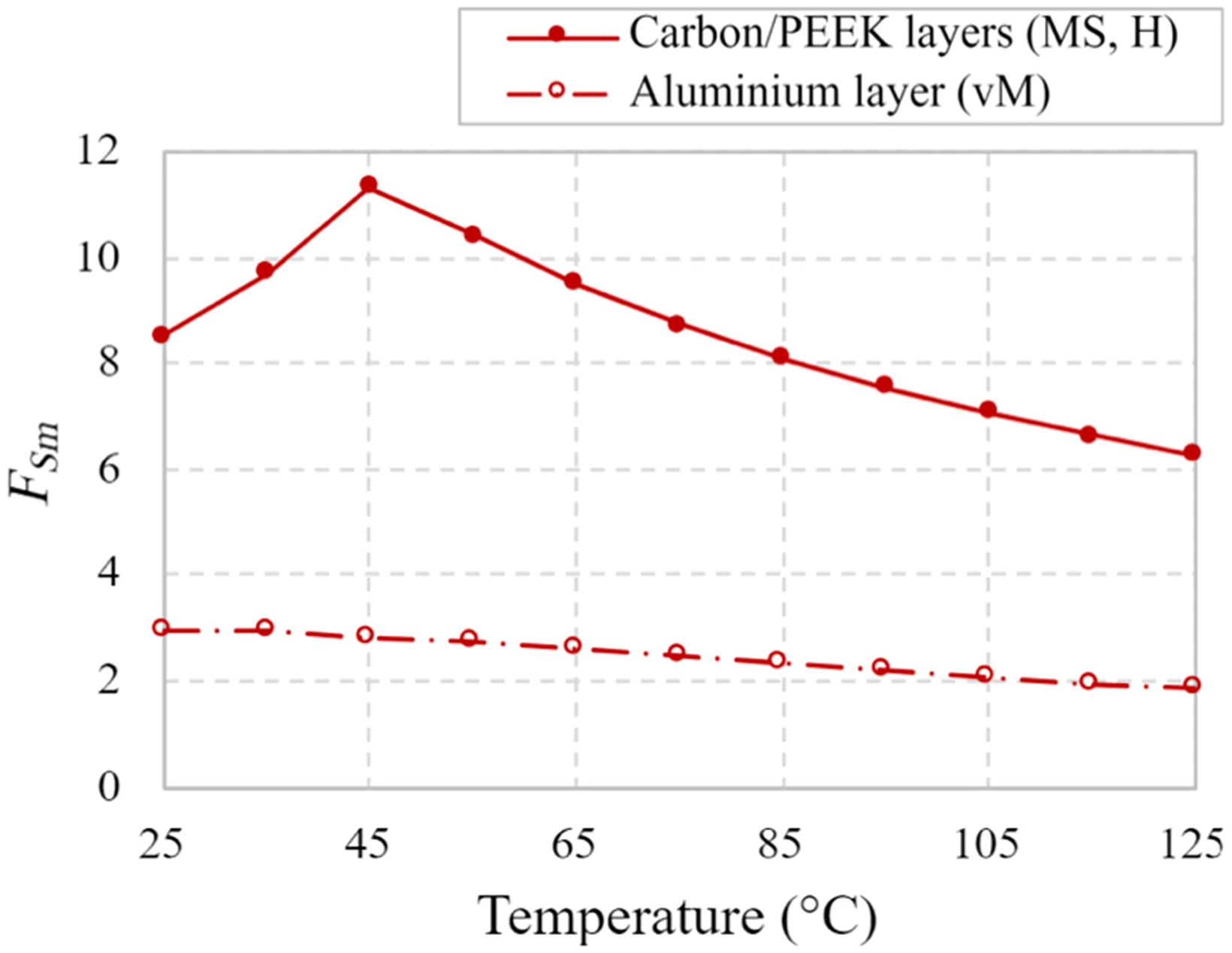
Variation of material safety factor with temperature for hybrid carbon/PEEK-aluminium driveshaft based on Max Stress (MS) and Hashin (H) for CFRP and von Mises (vM) for aluminium layer.
Figure 5 shows the safety factors for the hybrid carbon/PEEK-PEEK shaft. As with the aluminium hybrid, fibre compression factor for the carbon/PEEK increases initially as stresses redistribute with increasing temperature. Above 65 °C, the matrix compression Hashin mode becomes dominant and the factor decreases, while the Max Stress mode switches to transverse compression at 85 °C. Safety factor for the unreinforced plastic layer is highly sensitive to temperature and drops to 1.28, the lowest factor for any of the driveshafts, at 125 °C.
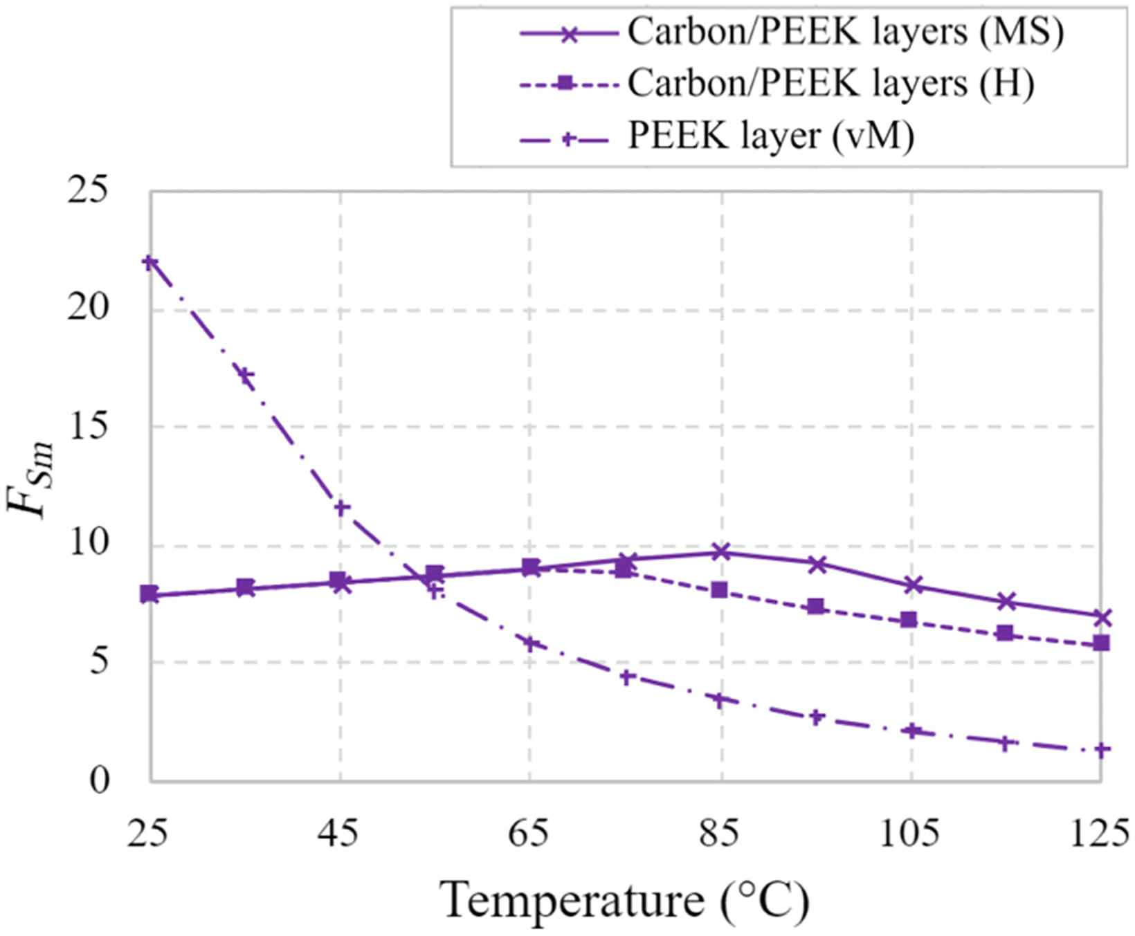
Variation of material safety factor with temperature for hybrid carbon/PEEK-PEEK driveshaft based on Max Stress (MS) and Hashin (H) for CFRP and von Mises (vM) for PEEK layer.
Shaft buckling
Linear analysis
The eigenmodes for the case of pure torsion were first determined by linear analysis. The initial two mode shapes corresponding to the same eigenvalue are shown in Figure 6 for the different driveshafts. The critical buckling torques for carbon/PEEK, aluminium and steel shafts are Tcr = 13.25 kNm, 36.57 kNm and 24.21 kNm, respectively. The aluminium shaft with the thickest cross-section exhibits the highest critical load, while the composite shaft exhibits the lowest as a manifestation of the anisotropy. Buckling torques for the hybrid shafts with aluminium or PEEK layer are Tcr = 23.47 kNm and 14.82 kNm, respectively. It is notable that the buckling load of the hybrid aluminium shaft is close to that of the heavier, homogeneous steel counterpart.
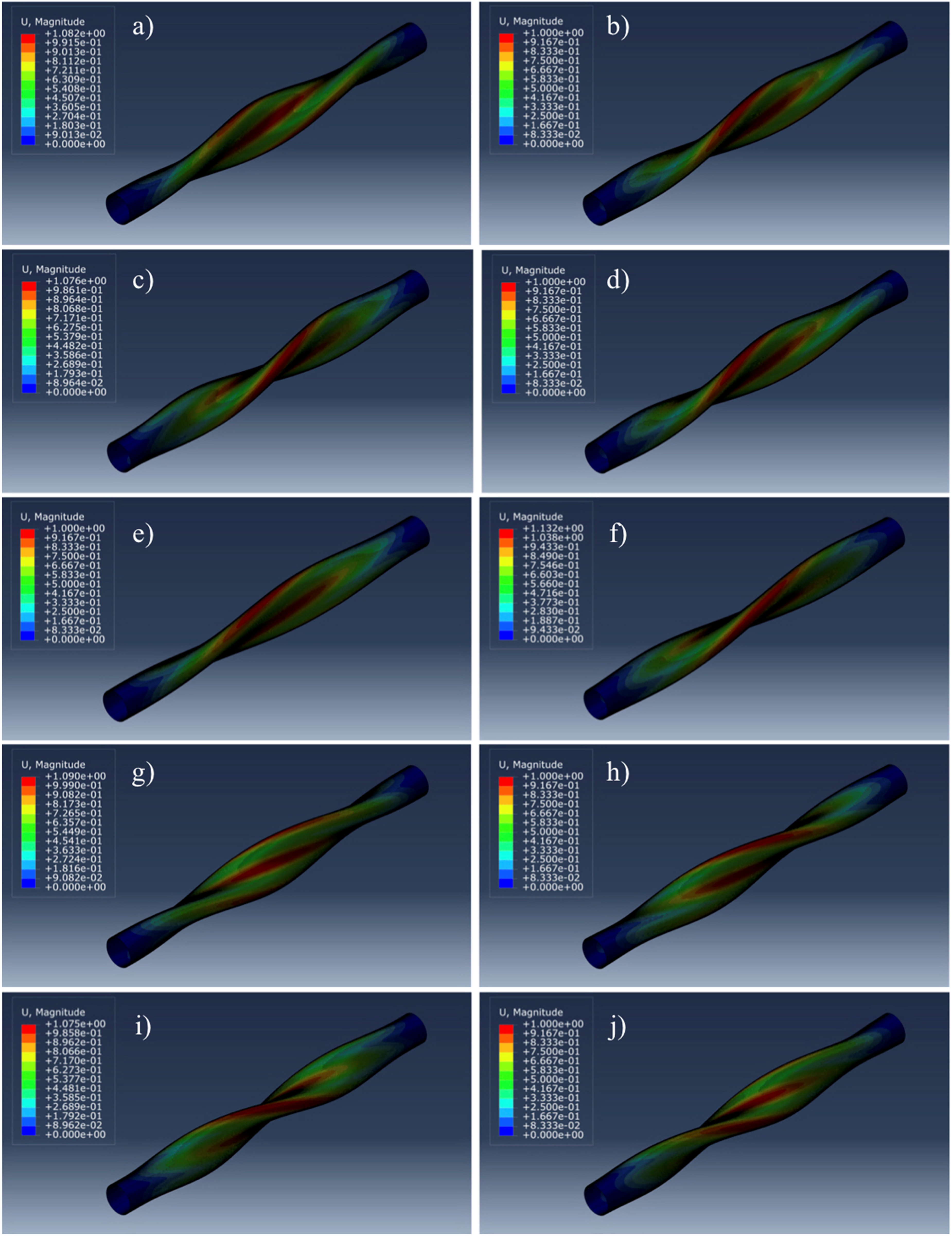
First two eigenmodes (scale factor 0.025) for all driveshafts: carbon/PEEK (a, b); aluminium (c, d); steel (e, f); carbon/PEEK-aluminium (g, h); carbon/PEEK-PEEK (i, j).
Nonlinear analysis
Imperfection sensitivity can be expected when two or more eigenvalues are identical or close to each other. Imperfections were applied to the driveshafts as the superposition of the first two modes corresponding to the same eigenvalue (the effect of including additional two lowest modes corresponding to reverse torque direction was found to be negligible). Normalised imperfection sizes of δ/t = 0.01, 0.05 and 0.1 were applied, where t is the thickness of the respective shaft.
Peak LPF versus imperfection amplitude for each driveshaft at 25 °C is shown in Figure 7. The steel part is the least imperfection sensitive, while the hybrid shaft with homogeneous plastic layer is the most sensitive to imperfection size. Manufacturers should account for this appropriately in shaft inspection procedures. LPFs at 125 °C are shown in Figure 8. Temperature rise from 25 °C to 125 °C causes a reduction in LPF, most significantly for the carbon/PEEK shaft, but overall sensitivity to the relative size of imperfection does not change appreciably with temperature in any case. The LPF for carbon/PEEK, aluminium and steel shafts falls by around 13.8%, 5.2% and 3.5%, respectively, with the +100 °C temperature change. The decreases for hybrid carbon/PEEK-aluminium and carbon/PEEK-PEEK shafts are 8.0% and 12.3%, respectively.
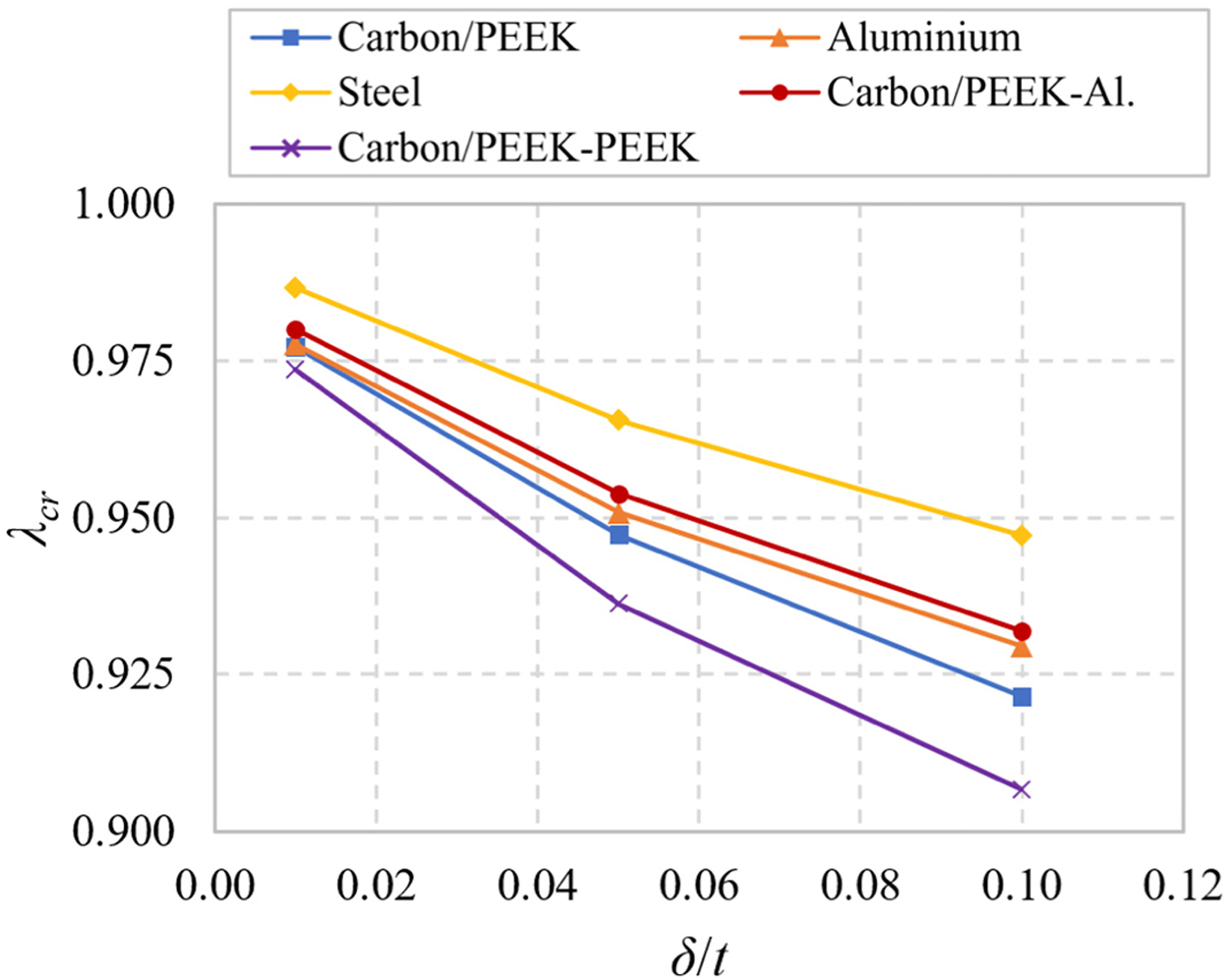
Peak LPF versus normalised imperfection amplitude at 25 °C for all driveshafts.
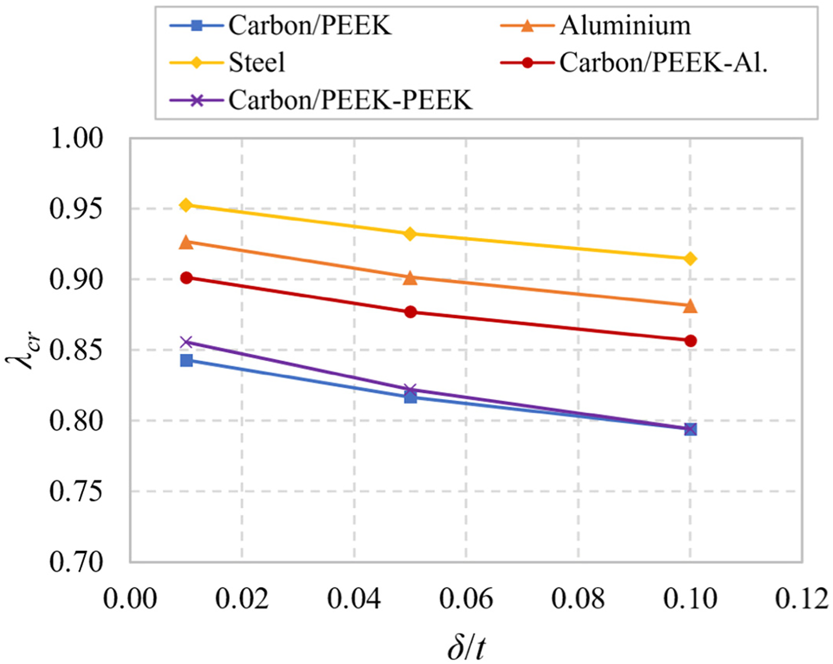
Peak LPF versus normalised imperfection amplitude at 125 °C for all driveshafts.
The variation in nonlinear buckling torque with temperature for each driveshaft is now shown in Figure 9 based on the largest imperfection amplitude of 10% of the respective shaft thickness. The carbon/PEEK and carbon/PEEK-PEEK driveshafts are clearly the most inferior in terms of buckling resistance. For an applied torque magnitude of 3500 Nm, the buckling safety factor for the carbon/PEEK shaft, which reaches a minimum of 3.01 at 125 °C, lies below the material failure factor (minimum 4.95 at 125 °C) over the full temperature range. Thus, global instability is of greater concern than local material failure. The opposite holds for aluminium, steel and hybrid aluminium shafts that exhibit high resistance to buckling but comparatively lower safety factor for yielding. For the carbon/PEEK-PEEK shaft, the buckling safety factor is lower than the material factor at low temperature but yielding of the PEEK layer becomes more critical at high temperature due to significant thermomechanical stress and reduced strength.
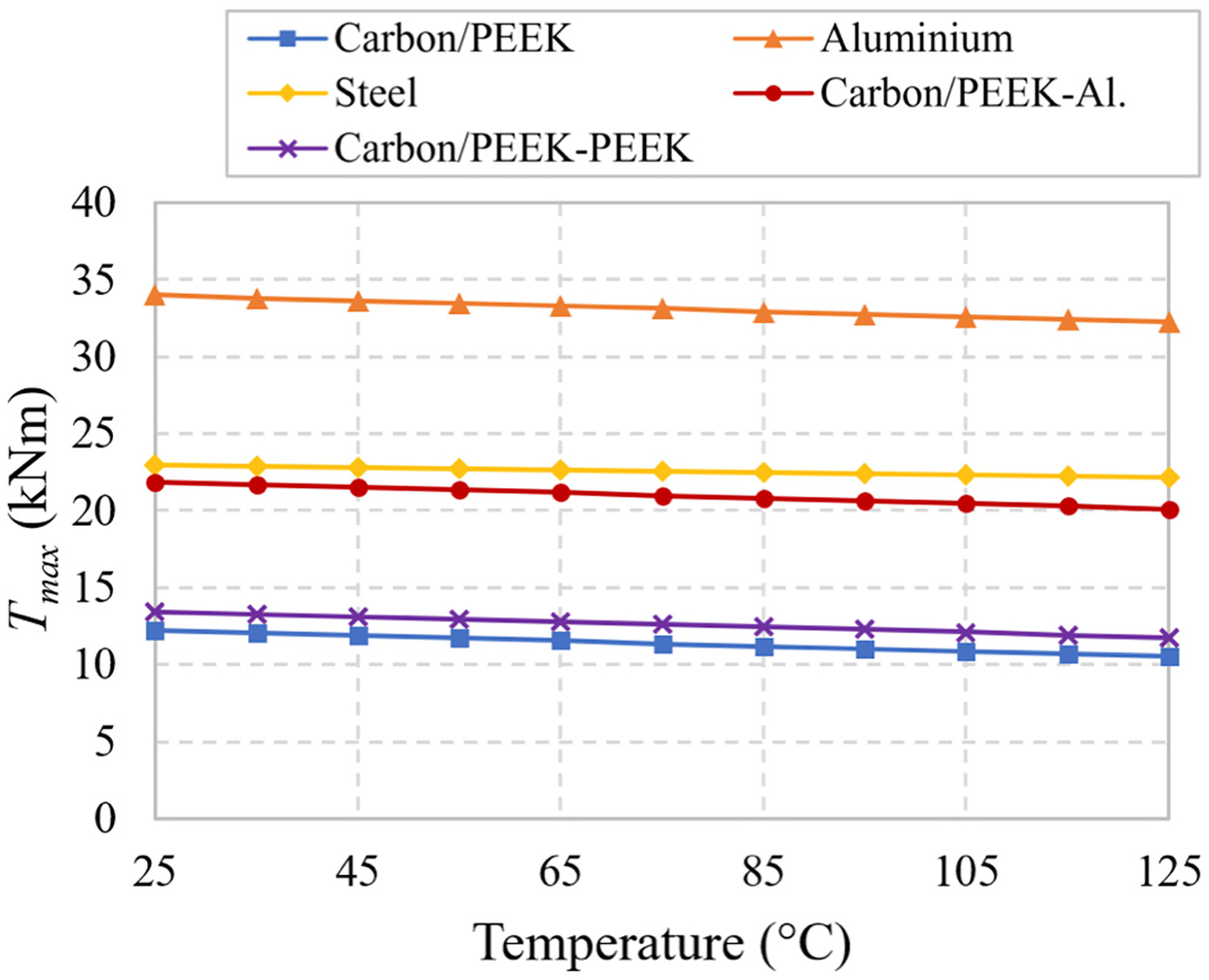
Variation of nonlinear buckling torque with temperature for all driveshafts.
Shaft critical speed
Lastly, critical speed as a function of temperature is shown in Figure 10 for all driveshafts. Critical speeds of aluminium and steel shafts are high and do not drop significantly with temperature owing to the good stability of elastic moduli. The hybrid carbon/PEEK-aluminium shaft response is close to that of the fully aluminium shaft. The carbon/PEEK shaft exhibits lower critical speed due to off-axis layer orientation and there is a more marked decrease with rising temperature. Even so, the carbon/PEEK driveshaft examined here satisfies the required minimum critical speed of 6000 r/min at 125 °C. We note that a higher natural frequency can be achieved by orientating plies at an angle lower than 45° to increase axial modulus at the expense of ultimate torque carrying capacity, as has been demonstrated for fibre-reinforced shafts without temperature consideration. 12 This trade-off may be examined in future considering temperature-dependent moduli. Critical speed of the hybrid carbon/PEEK-PEEK shaft lies below the required 6000 r/min at all temperatures and therefore such a configuration would be limited to applications involving low rotational speeds.
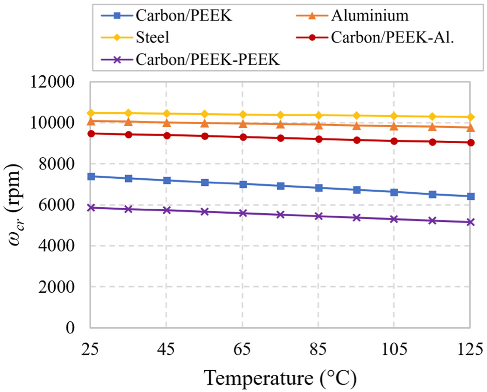
Variation of critical speed with temperature for all driveshafts
Summary of results
Material and buckling safety factors and critical speeds for composite, alloy and hybrid designs at low and high temperatures are summarised in Table 6. Overall, the carbon/PEEK driveshaft exhibits greater sensitivity to temperature than conventional aluminium and steel counterparts but safely satisfies the illustrative design requirements over the temperature range considered. With a mass of 2.28 kg, the carbon/PEEK shaft weighs roughly 48% of the aluminium shaft (4.71 kg) and roughly 31% of the steel shaft (7.32 kg). Such weight saving is highly desirable for practical automotive applications.
Summary of material and buckling safety factors and critical speeds at low and high temperatures for all driveshafts.
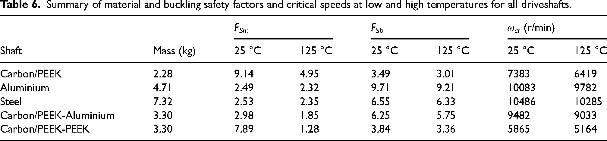
Compared to the fully carbon/PEEK part, the hybrid shaft with an inner aluminium layer exhibits inferior local material response, superior buckling resistance and higher critical speed (close to that of homogeneous aluminium part). Thus, such configuration may be a suitable design for applications involving higher rotational speeds. The shaft (3.30 kg) is heavier than the fully carbon/PEEK but still lighter than the alloy parts. The carbon/PEEK shaft with inner plastic layer exhibits a low material safety factor at high temperature and low critical speed. This concept may only be suitable for low-temperature, low-speed applications.
Conclusions
The behaviour of carbon/PEEK automotive driveshafts with/without inner homogeneous aluminium or plastic layer was analysed at varying uniform temperature in this paper. Temperature-dependent properties were considered. Material strength factor, buckling torque and critical speed were quantified over a shaft temperature range of 25–125 °C. Results were compared with traditional aluminium and steel shafts. The findings can be used to inform materials selection and practical design of composite driveshafts.
Material, buckling and natural frequency responses of a carbon/PEEK driveshaft are more sensitive to temperature than the responses of aluminium and steel counterparts. Notwithstanding, the composite shaft examined here satisfied the design parameters at maximum temperature. The shaft weighs 2.28 kg versus 4.71 kg and 7.32 kg for aluminium and steel shafts, respectively. A heavier carbon/PEEK shaft with an inner aluminium tube layer (3.30 kg) is more susceptible to material failure than the fully carbon/PEEK part but is better suited to applications where high rotational speeds are a primary design concern. A hybrid carbon/PEEK-PEEK shaft with same mass is not suited for high-temperature, high-speed applications.
The developed models can be used to investigate the response of alternative FRTP materials in practical driveshaft applications. Future work will investigate the effects of varying layer fibre orientation on composite and hybrid driveshaft responses at elevated temperature.
Footnotes
Authors' contributions
JCH: Conceptualisation; Methodology; Investigation; Software; Writing - Original Draft; Writing - Review & Editing. IAG: Conceptualisation; Methodology; Investigation; Writing - Review & Editing; Supervision. MK: Conceptualisation; Methodology; Investigation; Writing - Review & Editing; Supervision.
Funding
The author(s) received no financial support for the research, authorship, and/or publication of this article