
Abstract
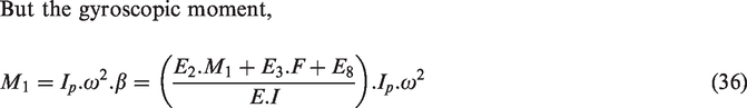
The paper investigates the use of compensating balancing sleeves positioned at the shaft’s end for the balancing of high-speed flexible shafts. The balancing sleeve is a new arrangement that creates a pure balancing moment with virtually zero radial reaction forces. For comparison purposes, experimental results from previous research are used to benchmark performance and to demonstrate the benefits newly proposed topology. The new configuration is commensurate with what is required for the Power Turbine (PT) shaft of a twin shaft industrial gas turbine, with an overhung disc. The study is also aimed at bladed shafts, such as those used in high speed gas turbines/compressors, with a view to improving their volumetric efficiency by reducing the formation of relatively large tip leakage gaps caused by shaft deflection/blade wear of abradable seals. It is shown to be practically possible to separate the two main dynamic balancing functions i.e. the control of bearing reaction loads and shaft deflections, thus allowing for their independent adjustment. This enables the required balancing sleeve moment to be determined and set during low-speed commissioning i.e. before any excessive shaft deflection and resulting seal wear occurs, as is typical when final balancing is undertaken at full operational speed.
Introduction
Achieving a high degree of balance is of critical importance to all forms of high speed rotating machinery employing flexible shafts. The lack of it usually produces very high centrifugal forces which consequentially can cause: excessive vibration requiring machine shut down to prevent bearing failure; excessive shaft deflection leading to rub/wear of components such as seals, turbine/compressor blades; excessive temperature/material creep; loss of performance/efficiency; excessive stresses, etc. Hence the subject of shaft balancing has been the subject of intense research since the start of the industrial revolution, with Rankine 1 in 1869 and Jeffcott 2 in 1919 making important early contributions, evaluating the first critical speed and analysing the rotation of the mass centroid, respectively.
It is appreciated that manufacturing precision can never be perfect and consequently all shafts and rotors will contain a degree of mass unbalance due to asymmetry and machining imperfections. Modern balancing standards recognise this fact and set suitable limits according to machinery application for two classifications of rotors: rigid3,4 and flexible. 5
Rigid rotors are comparatively easy to balance having a maximum of two resultant unbalanced forces acting on the bearings/supports, producing two modes of vibration/critical speeds: a transverse bounce or a conical tilting motion without any flexing of the rotor. This dynamic unbalance can be corrected by two balance weights being radially positioned in two different balancing planes, either in-phase or 180° out of phase, as necessary. The rigid definition determines that no significant bending deformation must occur which generally limits the maximum operating speed to be less than 75% of its lowest flexural critical speed. 6
At higher speeds special techniques for balancing flexible rotors are required and these are generally sub-divided into either Influence Coefficient or Modal Balancing methods, which were introduced in the 1930s and 1950s, respectively.
The Influence Coefficient method 6 uses trial masses placed in given balancing planes to determine variations in measured response relative to that of the corresponding residual unbalance, for a set of trial test speeds. Hence, by assuming a linear system and using simple vector analysis, the influence of the trial masses can be used to determine the required magnitude and angular position of the correcting masses needed to balance the rotor.
Modal balancing uses a mathematical model of the system, shaft and supports, to determine a relationship between the shaft displacement and its forcing functions resulting from points of residual mass unbalance for each of the critical speeds within the operating speed range. Typically these models either constitute a series of mass unbalances, 7 or one in which the shaft is treated as a continuous elastic body.8–10 More recently, modern computing has increased the accuracy of these models thereby allowing research to concentrate on reducing costs by conducting modal balancing with a single transducer or without trial masses.11,12
A good review of current balancing methods 13 concludes that the capability/availability of today’s high powered computers makes the differences in balancing methods more a question of economics than capability.
Recent work has investigated the possibility of automatic/active balancing whereby masses are given a limited movement to allow for real-time balance correction across a range of speeds. One such example with positive results showed a rigid rotor where the degree and position of unbalance changed over a period of time; however, for flexible shafts/rotors it remained difficult to achieve satisfactory results over a given speed range.6,14 Similarly, the research into the use of controllable bearings, actuators and sensors to measure and control vibration, continues to be work-in-progress due to complexities surrounding control systems and the high-cost of implementation. 14
An alternative balancing methodology has recently been proposed,15–17 whereby compensating balancing sleeves are used to replicate the fixing moments of an equivalent encastre shaft thereby effectively making the shaft dynamically stiffer. This research showed (supported by experimental test data from a scaled industrial turbine coupling shaft) that it is possible to effectively reduce the residual level of shaft eccentricity by 96%, i.e. to 1/25th of its actual physical quantity for certain shaft configurations. Also, because this reduction ratio was derived from unit load deflections of the simply supported shaft and its encastre equivalent, it is independent of their common eccentricity and hence its beneficial effects are additional to reductions in residual eccentricity obtained during traditional component/assembly balancing operations. Further the work revealed that single ended encastre simulation is also effective so that balancing sleeve compensation need only be applied at a single shaft end.
However, this work was confined to balancing sleeve compensation applied internally, i.e. between the shaft simply supported points formed by either the bearings or by coupling flexible elements. Such positioning can have economic consequences during commissioning/servicing operations due to lack of accessibility and is not always practical because of internal space limitations.
Consequently, the current research in recognising the commercial benefits of external application is aimed primarily at checking the feasibility and efficacy of fitment beyond the bearings, at a machine’s output shaft end, external to its housing/casing. Hence, for comparison purposes the first analysis is based on the same scaled industrial turbine coupling shaft as used in the former research described above. Subsequently, a new, second configuration considers a typical Power Turbine (PT) shaft of a twin shaft gas turbine, with an overhung disc. Both examples are applicable for consideration of bladed shaft layouts, such as those used in high-speed gas turbines or industrial compressors, with a view to improving their volumetric efficiency by reducing the relatively large tip leakage gaps created by rubbing action of blades on abradable seals during shaft deflection.
Further, it is shown by simple analysis that it is practically possible to separate the two dynamic balancing functions: control of bearing reaction loads and shaft deflections, by a novel form of compensating balancing sleeve. This allows for their independent adjustment and consequently greatly simplifies the complex problem of balancing high speed, flexible shafts.
Theoretical analysis – External balancing sleeve applied to a shaft with a concentrated imbalance between bearings
It is notable that most high speed flexible rotors are dynamically very complex because of variations in both physical assembly and support structure. Bearings for example can be simple journal/bush assemblies, complex slipper pan arrangements, both with pressurised lubrication so that the rotating shaft sits on a film of oil; or more rigid rolling element types often used in aero-derivative gas turbines. Hence, a complete rotor dynamic analysis would include their respective stiffness and damping characteristics to produce the full magnitude of lateral forces/movement. However, the proposed method uses the same basic approach as presented in Knowles et al.15–17 on the understanding that it is intended as a feasibility study and that final confirmation of its conclusions can be subsequently checked by finite element analysis (FEA) and development testing.
The first configuration of this investigation represents a typical high-speed machine such as an industrial compressor containing of a concentrated imbalance positioned between a pair of bearings, i.e. simply supported points and for comparison purposes the model and its dynamic parameters comprise the same as those used in a previous study, by Knowles et al., 17 of a scaled industrial turbine coupling shaft. Hence it is appropriate to base this analysis on the same basic model with the exception that the original balancing sleeves are replaced by a balancing devise producing a moment at the free end of an extended shaft. Thus, the same analytically derived equations can be utilised provided the external balancing moment and its reaction load are expressed in terms equivalent to their corresponding parameters formulated at the first bearing position in the original analysis, thereby allowing the previous experimental results to be used for validation purposes. For reference these details are given in Appendix 1.
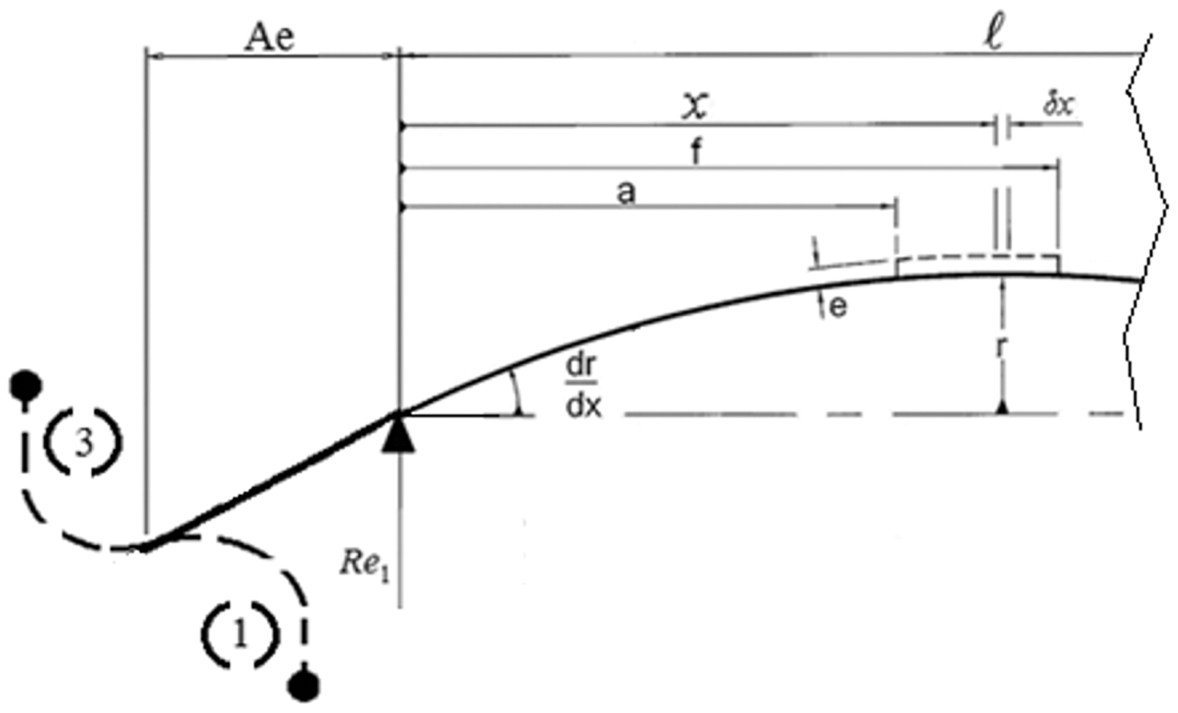
The mathematic model of the original shaft is shown in Figure 1, with an additional front end extension of length Ae included to represent the external input/output shaft end of a driver or driven machine, together with four new possible compensating balancing sleeve positions, shown dotted, as replacements for the original, internally applied sleeve depicted by solid lines. Figure 1(a) shows a schematic of these combined balancing sleeve design options.
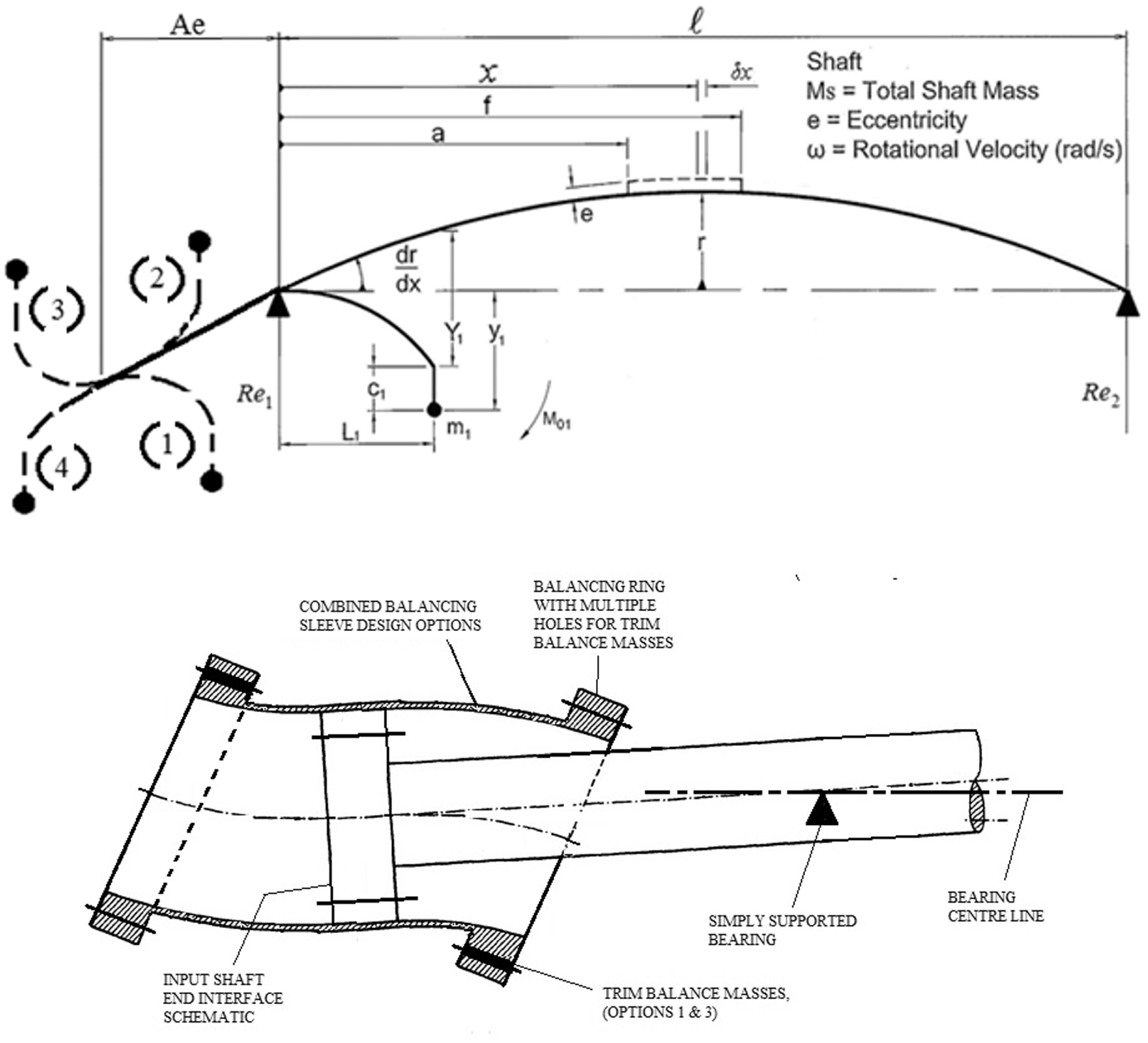
Schematic of an extended simply supported shaft with concentrated eccentricity: (a) schematic of combined balancing sleeve design options.
Balancing sleeve design options
Figure 2 shows a scheme 1 balancing sleeve together with the formulation of its equivalent balancing moment and reaction load as applied to the shaft at the left hand side (LHS) bearing position so as to correspond with the orientation of the original analysis.
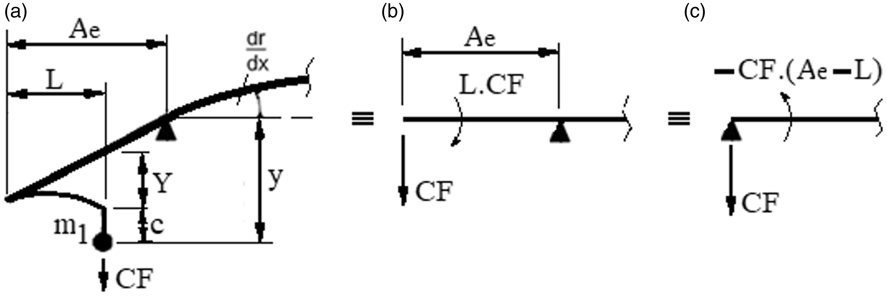
Equivalent balancing moment and reaction load produced by a scheme 1 balancing sleeve.
Using standard convention whereby sagging bending moments, tending to make a shaft dip, are positive and hogging moments are negative it is apparent from Figure 2(b) that the CF acting on the balancing sleeve mass, m1, produces a positive, sagging, balancing sleeve moment, equal to L.CF, similar to that shown in Figure 1, but the reaction load acting downward on the shaft end produces a larger negative moment so that the resulting moment seen at the bearing, Mo, is negative and equal to – CF. (Ae - L) as shown in Figure 2(c).
This can be evaluated by consideration of the CF acting on the trim balancing mass, m1, and the lateral force balance provided by the balancing sleeve spring stiffness, (K), which determines that

Furthermore, inspection of Figure 2(a) for small angles of slope and neglecting any curvature of the shaft extension, Ae, yields the radial extension, y, of the balancing mass from the axis of rotation


Equations (3) to (5) are in the same format as those of the original analysis by Knowles et al. 17 and hence permits their use in the prior characteristic equations for shaft deflection and bearing reaction loads for the analysis of the new shaft configuration.
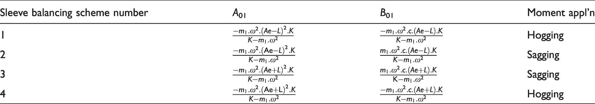
Similarly, equivalent balancing sleeve moment/parameter values of Schemes (2) to (4), have been evaluated and are presented in Table 1.
Balancing sleeve parameter values – schemes 1–4.
Reactionless compensating balancing sleeve
Study of this table and the respective layout configuration of the schemes shown in Figure 1, reveals that while a reaction force produced by the balancing sleeve is beneficial for “between the bearings” installations, it is detrimental for external applications, as it either increases the load applied to the bearings by acting upwards or that it produces a hogging balancing moment thereby causing the shaft deflection to increase when acting downwards. However, lateral reaction forces are not require to reduce shaft deflections, as this is accomplished by the balancing moment and also, provided the shaft deflections are substantially reduced, the bearing loads can be controlled using a low speed “Rigid Body” balancing procedure with corrections applied close to the bearings. Note, trim balance adjustments at these positions do not affect the bending of the shaft thereby making the control of lateral bearing loads and shaft deflection, mutually independent of one another. This is advantageous as it greatly simplifies the normally complex problem of balancing high speed, flexible shafts.
Hence, it is evident that for external applications, a Reactionless Balancing Sleeve, i.e. one that produces a balancing moment with the same amplification properties as before, but with near zero lateral loading, would be more beneficial than the compensating balancing sleeves of earlier studies. This is shown schematically in Figure 3 as a combination of schemes 1 and 3, where the two CF’s combine to produce a positive sagging bending moment, but oppose each other so that the lateral force applied to the shaft is virtually zero. Thus, the parameters of the equivalent balancing moment are simply given by the addition of the individual schemes
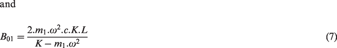

Schematic of a reactionless, compensating balancing arrangement.
Note, at near optimum compensation, with good encastre simulation, the shaft slope at the first bearing is minimalized so that the reaction force is very small; this also simplifies the balancing moment which becomes
However, the moment is now double that of a single sleeve, so that although the combined mechanism may appear to be more complex, the new arrangement can actually produce a very compact unit since the length of each sleeve is reduced.
Analytical results – Scaled test shaft with an externally applied reactionless compensating balancing sleeve
To allow comparison with the theory/test results of the Knowles et al. 17 paper, the analytical representation of an externally applied, reactionless balancing sleeve used identical shaft parameters as per the original scaled test shaft, as shown in Table 2, but with equations (6) to (8), used to determine the new balancing sleeve parameters.
Parameter values used for numerical studies of the scaled test shaft.
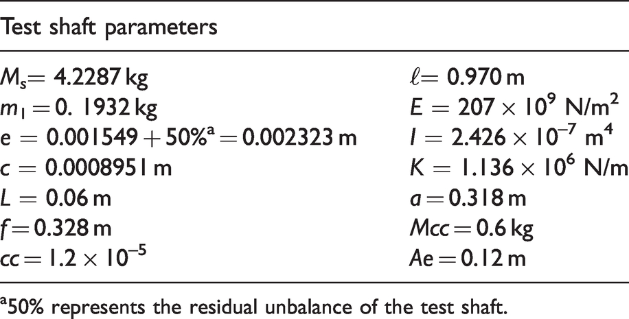
a50% represents the residual unbalance of the test shaft.
Maximum compensation, theory and test results, are shown in Figure 9(a) of Knowles et al. 17 and were produced with a combination of sleeve moments, Mo1 = 18.4 Nm and Mo2 = 9.7 Nm to give a total balancing moment of 28.1 Nm. For completeness, Figure 9(a) together with a brief analysis is repeated in Appendix 1.
For the new arrangement the given equations were inserted into a Mathcad program and adjustment of its balancing moment was made by varying the eccentricity of the balancing sleeve mass, c, to obtain a near optimum reduction in shaft deflection. This condition, as expected, produced a moment of 28.1 Nm to tally with the total compensation moment above.
Results, with and without balancing sleeve compensation, are shown graphically in Figures 4 and 5. It is noted from Figure 4 that the reduction in shaft deflection is equally as good as before for operating speeds up to 10,000 r/min. Figure 5 shows the difference in shaft profile for the compensated and uncompensated cases and supports the previous claim that with a high degree of compensation the shaft deflection is very small and consequently it can be treated as a rigid rotor for balancing purposes.
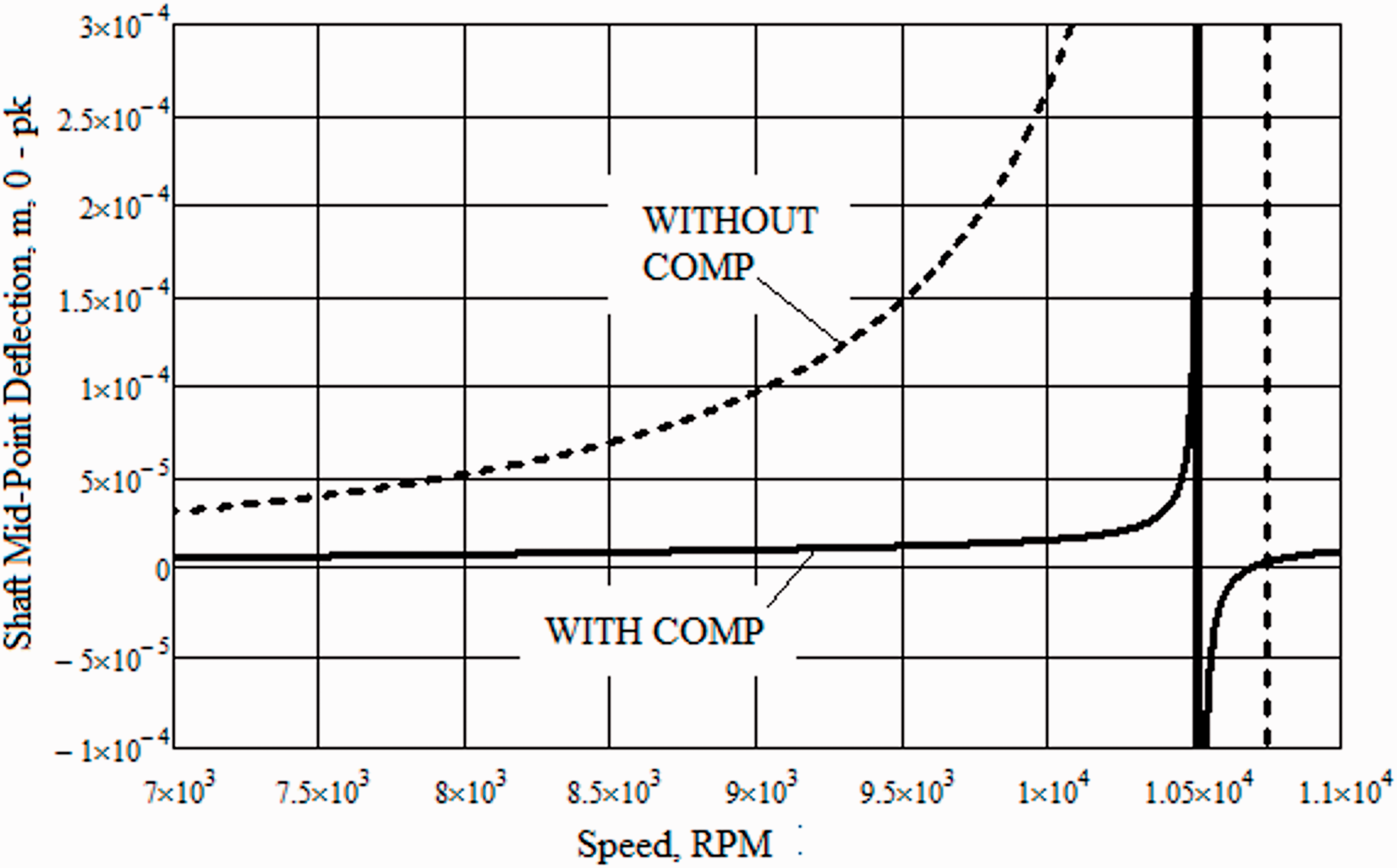
Shaft mid-point deflection versus speed, with and without compensation, for the scaled test shaft configuration (optimum deflection moment, M01 = 28.1 Nm at 10,000 r/min).
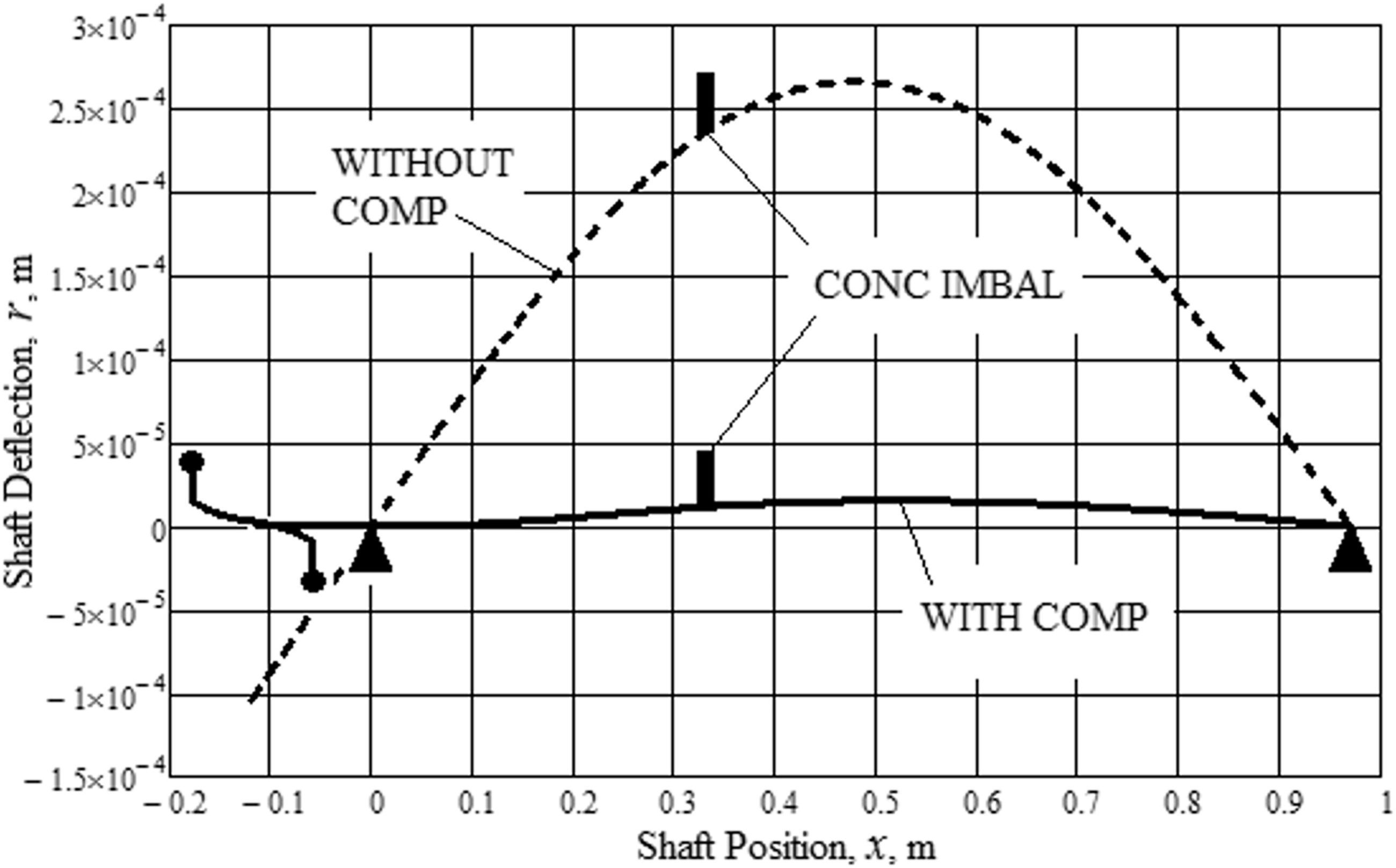
Shaft deflection profile, with and without compensation at 10,000 r/min, for the scaled test shaft configuration, (optimum deflection moment, M01 = 28.1 Nm at 10,000 r/min).
The practicalities of reducing seal leakage from bladed shafts
For the practical representation of say an industrial compressor the model must be modified by the addition of a point mass at the shaft end to represent the ½ mass, Mcc, of a drive coupling and the mass of the balancing sleeve. Rotation of this mass then imparts a CF and a hogging moment onto the shaft which requires an extra term to be added to each of the previous parameter equations (6) to (8), as follows


The importance of the roll shaft deflection plays in the leakage between successive bladed stages of a compressor or turbine can be assessed by considering the axial cross sectional area (csa) of the leakage gap created by localised deflection,
However, most bladed machinery makes use of abradable seals in order to minimise blade damage during periods of incidental rub between the blade and its outer casing. Hence it is evident that if a low leakage associated with a low deflection is to be achieved then a higher shaft deflection must be prevented during commissioning as this would cause permanent enlargement the inner diameter of the seal. This means that the required balancing sleeve moment must be determined and applied during commissioning at a speed in which the unbalanced shaft deflection does not exceed the desired fully balanced deflection at maximum operating speed. This speed can be determined from midpoint deflection curves similar to those shown in Figure 4, but with the added ½ mass modification, as per equations (9) to (11) to represent a driven unit such as an industrial compressor. For the purpose of this exercise the maximum commissioning speed has been determined to be 6000 r/min and in keeping with a real case scenario the magnitude and position of the residual unbalance is assumed to be unknown.
Estimation of equivalent eccentricity and required balancing moment
Knowles et al. 17 established that a shaft with concentrated imbalances may be adequately regarded as a shaft with an equivalent level of uniform eccentricity since individual imbalances, at a running speed close to critical, have a concentrated imbalance coefficient, k, which is a fixed ratio between the actual balance condition and that of an equivalent shaft. Hence, from measurements of bearing reaction loads, taken during commissioning, the required balancing moment can be obtained.
If initial commissioning tests are performed with zero compensation the balancing moment will be solely produced by the ½ mass at the extended shaft end. The magnitude of the coupling/sleeve assembly ½ mass will be known from design details and only its eccentricity, 
This expression, together with the average bearing reaction load can be incorporated into the derived equations of an earlier work by Knowles and Kirk 15 into shafts with uniform eccentricity to calculate an equivalent level of uniform eccentricity and a required balancing moment of the real shaft with unknown levels of residual unbalance. These equations are shown below with details provided in Appendix 2.
Equivalent eccentricity of the real shaft is given by

Since the modelled shaft with uniform eccentricity is perfectly symmetrical its reaction loads will be identical, hence its determination uses the measured values from both shaft ends obtained from each of the positive and negative ½ mass eccentricity runs.
The analytical model described in “Estimation of equivalent eccentricity and required balancing moment” and “Theoretical analysis – External balancing sleeve applied to a shaft with an overhung disc” sections has been used to represent a real shaft and provide the test data for an illustrative exercise using the assumption that details of the residual unbalance are unknown. A ½ mass eccentricity, cc = 1.2 × 10⁻⁵ m, as per American Petroleum Institute, API Standard 671 18 maximum recommendation for an estimated ½ mass = 0.6 kg, at a maximum speed of 10,000 r/min, is included. It has also been assumed that a the fully assembled shaft, without the coupling ½ mass, would have been separately trim balance corrected at the bearing positions as previously described in “Reactionless compensating balancing sleeve” section, on a balancing machine at a speed of 2000 r/min and the unbalance figures before correction noted, (Uc1 = 69.6 g mm, Uc2 = 35.7 g mm calculated from the scaled shaft analysis). At such a low speed the shaft will have very little deflection, thereby ensuring that the corrected state of the reaction loads will be maintained at higher speeds providing shaft bending is adequately controlled by the compensating balancing moment. To represent this scenario the calculated value of the reaction loads have accordingly been reduced. Two Mathcad program runs were made using positive and negative values of the ½ mass eccentricity representing the 180° rotation of the coupling/sleeve and the corresponding shaft end reaction loads are shown in Figure 6 to represent the commissioning tests at speeds up to 6000 r/min.
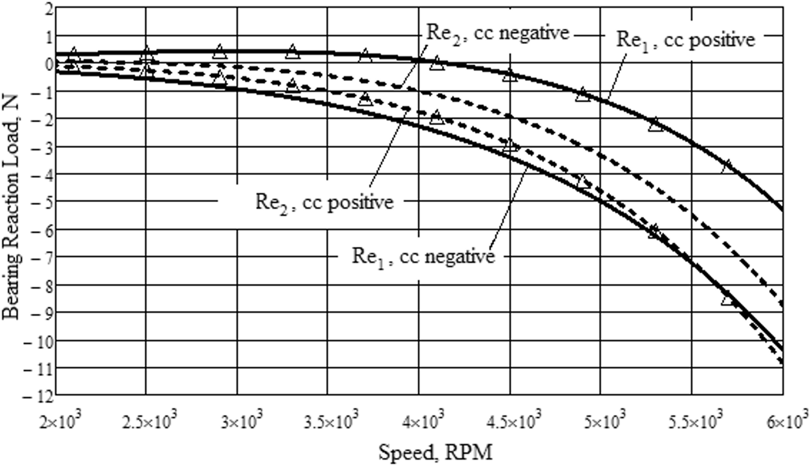
Commissioning test results: reaction load versus speed.
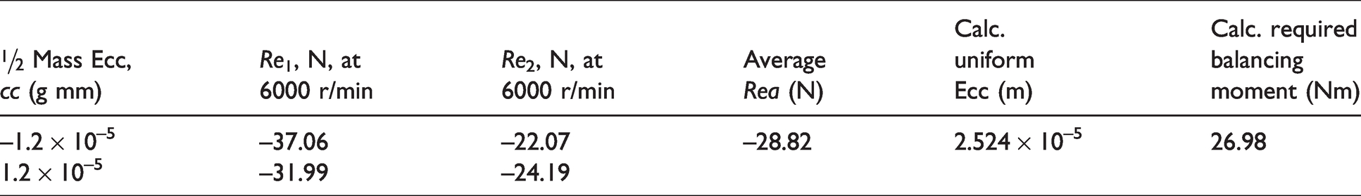
However, it is the magnitude of the reaction loads before the trim balancing operation, that must be used for the estimation of the equivalent eccentricity/required balancing moment, hence the magnitudes of their CF reductions at the commissioning test speed, 6000 r/min, (CF1 = 26.67 N, CF2 = 13.31 N, derived from Uc1 and Uc2 figures above), must be added to the corresponding reaction loads given in Figure 6. Their average was then used to determine the equivalent eccentricity/required balancing moment from equations (13) and (14) above. These results are displayed in Table 3 and it can be seen that the required balancing moment, 26.98 Nm, derived solely from the results of the low speed test simulation compares very well with that from the scaled coupling test, 28.1 Nm, described in “The practicalities of reducing seal leakage from bladed shafts” section.
Parameter values used for numerical studies.
It is now assumed that the eccentricity of the balancing sleeve, c, would be adjusted to give the calculated balancing moment, 26.98 Nm, so that the represented real shaft could now be safely operated at its maximum speed of 10,000 r/min, without fear of excessive shaft deflection causing permanent enlargement of the abradable seals.
To assess the level of compensation afforded by this estimation the Mathcad program was accordingly re-set and the theoretical shaft deflections and profiles, with and without compensation, are shown in Figures 7 and 8.
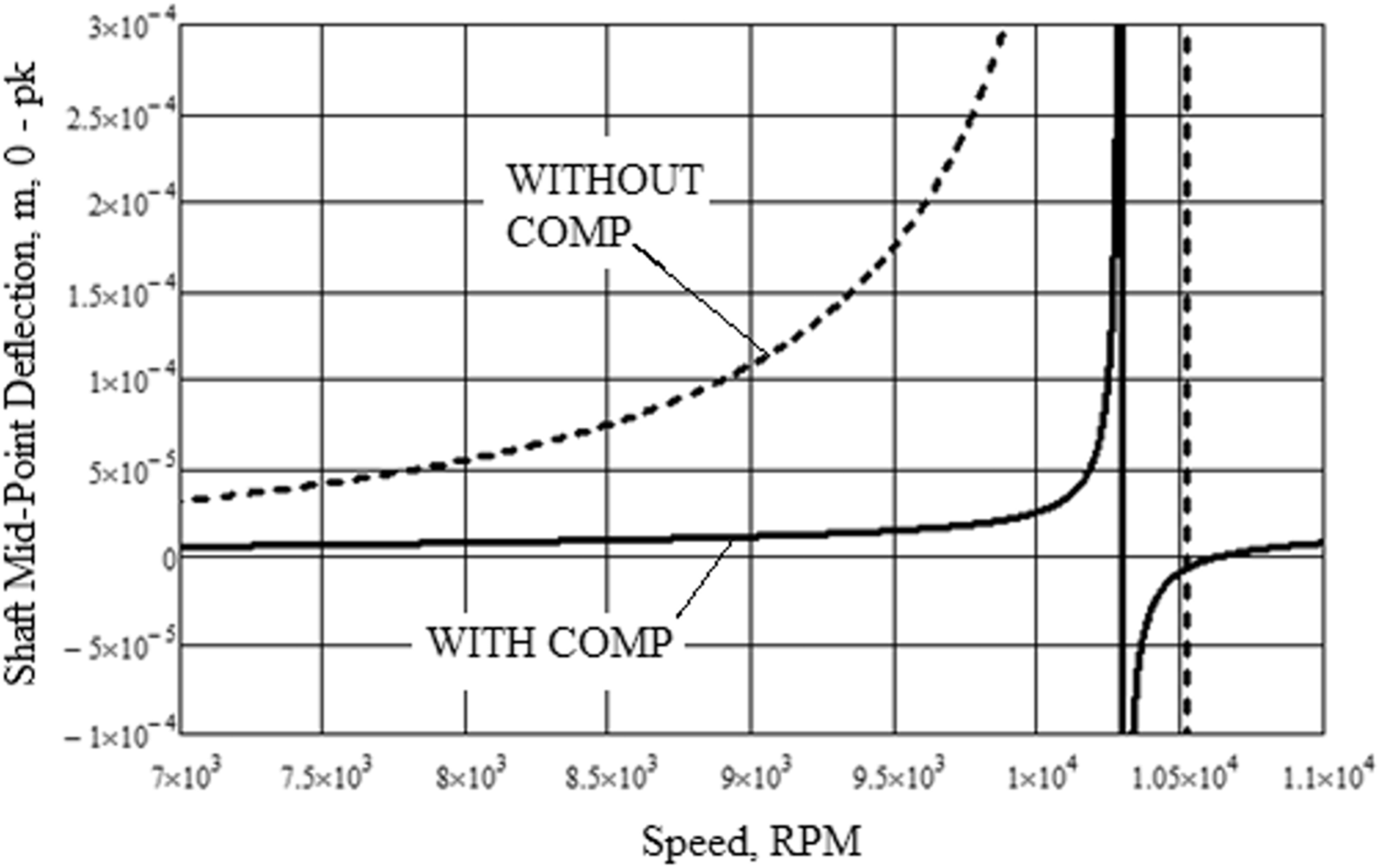
Shaft mid-point deflection versus speed, with and without compensation (set to balancing moment estimation, M01 = 26.98 Nm at 10,000 r/min).
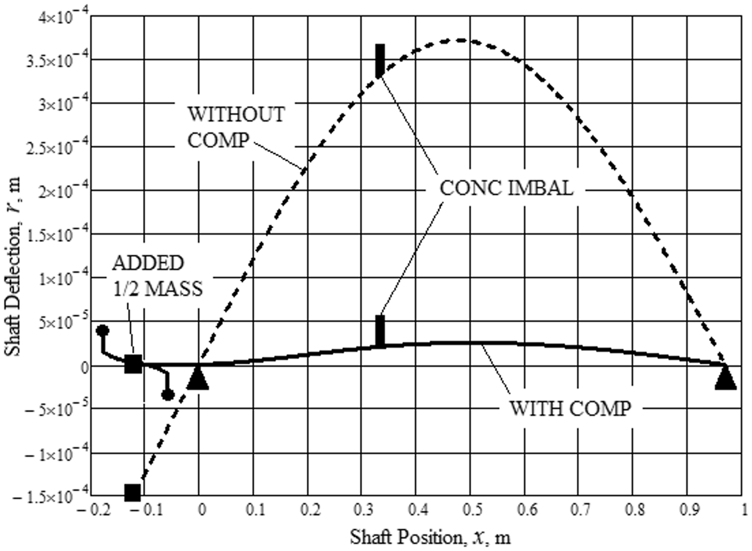
Shaft deflection profile, with and without compensation at 10,000 r/min (set to balancing moment estimation, M01 = 26.98 Nm at 10,000 r/min).
It can be seen that the addition of the coupling ½ mass has reduced the critical speeds by approximately 200 r/min, which is to be expected in a real shaft scenario and that the compensated level of shaft deflection is very similar to that shown previously in Figure 4 where the balancing moment had been optimized.
Therefore, these results confirm the practicality of the above procedure for predetermining/setting the required balancing moment during low speed commissioning tests thereby preventing any further enlargement of the abradable seals at full operating speed so that seal leakage, together with shaft deflection, will be correspondingly reduced.
Theoretical analysis – External balancing sleeve applied to a shaft with an overhung disc
A second configuration of this investigation represents the power turbine shaft of a typical twin shaft industrial gas turbine with an overhung disc by using a classical model of a massless shaft with an unbalanced overhung disc as shown in Figure 9. In the initial calculation, a single balancing sleeve is positioned internally as per the earlier example, i.e. between the bearings, but adjacent to the second bearing which would represent the output bearing of a real machine, and its moment is expressed in the same parameters terms As and Bs, as previously defined, thus enabling their later modification by substitution of corresponding reactionless balancing sleeve and ½ mass equations. This simplification allows the formulation of a general bending moment equation comprising the individual loads and moments acting on the shaft at any axial position, x, by Macaulay’s Method, whereby when the terms inside square brackets are negative they are equated to zero. Hence, by subsequent integration it is possible to determine first, the slope of the shaft and secondly its deflection, as shown below.
Schematic of simply supported, rotating shaft with concentrated eccentricity: (a) (Ref Paper) comparison of theoretical and test levels of LHS balance compensation, CR = 1.037, M01 = 18.4 Nm, M01 = 9.7 Nm, and total moment = 28.1 Nm.
The massless shaft and overhung disc
Note, F, Md, and Ip respectively refer to the inertia force, mass and polar inertia of the disc; likewise Fs and ms refer to similar properties of the balancing sleeve and linear distances/moments are as depicted in Figure 9. Then, from traditional ‘Bending of Beams’ theory, the bending moment, Mx, at any point, x, along the shaft, is given by
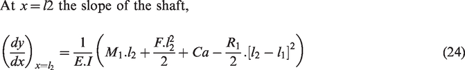
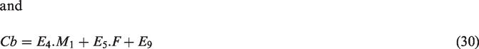
Integration with respect to x, where Ca and Cb are the constants of integration, gives

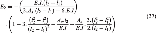
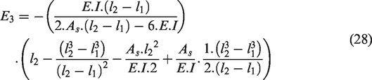
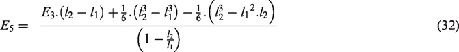
Applying the following boundary conditionsat x = l1 and x= l2, y = 0, and further algebraic simplification gives

Forces/moments acting on the compensating balancing sleeve yield


Considering the combined assembly


Overhung disc only
The angular and linear displacements of the disc are determined from the beam equations at x = 0.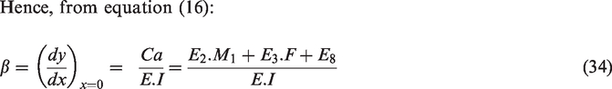
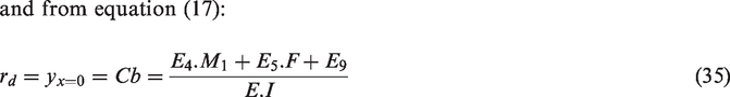


Hence substituting for F from equation (39) and re-arranging gives
Reaction forces
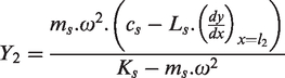
By inspection of Figure 9 it is apparent that the centrifugal force acting on the mass of the balancing sleeve and the subsequent reaction force at the second bearing is given by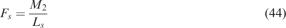

Hence, all unknowns are determined for an internally mounted balancing sleeve and it is only necessary to analyse the new equivalent sleeve parameters, As and Bs, appropriate to this configuration. Application of the same procedure as used in “Reactionless compensating balancing sleeve” and “The practicalities of reducing seal leakage from bladed shafts” sections for the reactionless balancing sleeve and the coupling/sleeve ½ mass, determines that the same equations apply; namely, equations (6), (7), (9), and (10), respectively, except that each one requires a sign change since in this configuration the moments produced are hogging/negative.
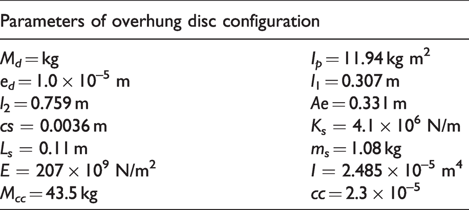
A Mathcad program based on the above equations, with parameter values as given in Table 4, was used to graphically determine the disc deflection versus operating speed and the shaft profile at a nominated shaft speed of 12,500 r/min (approximately 91% of critical), both with and without optimised balancing sleeve compensation, as shown in Figures 10 and 11.
Parameter values used for numerical studies of the overhung disc configuration.
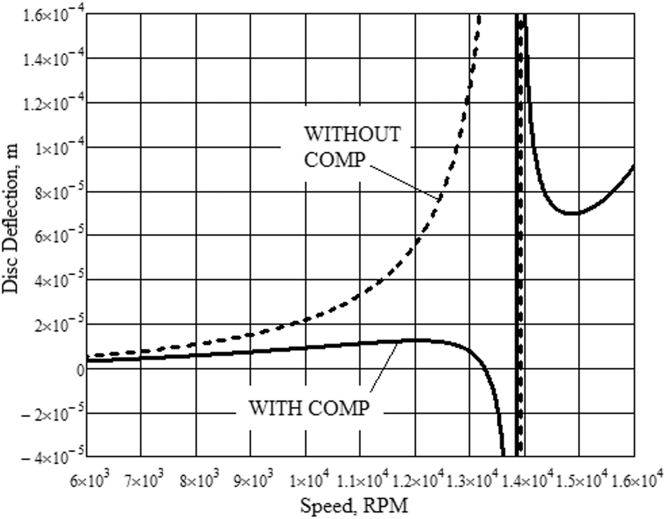
Shaft disc deflection verses speed, with and without compensation.
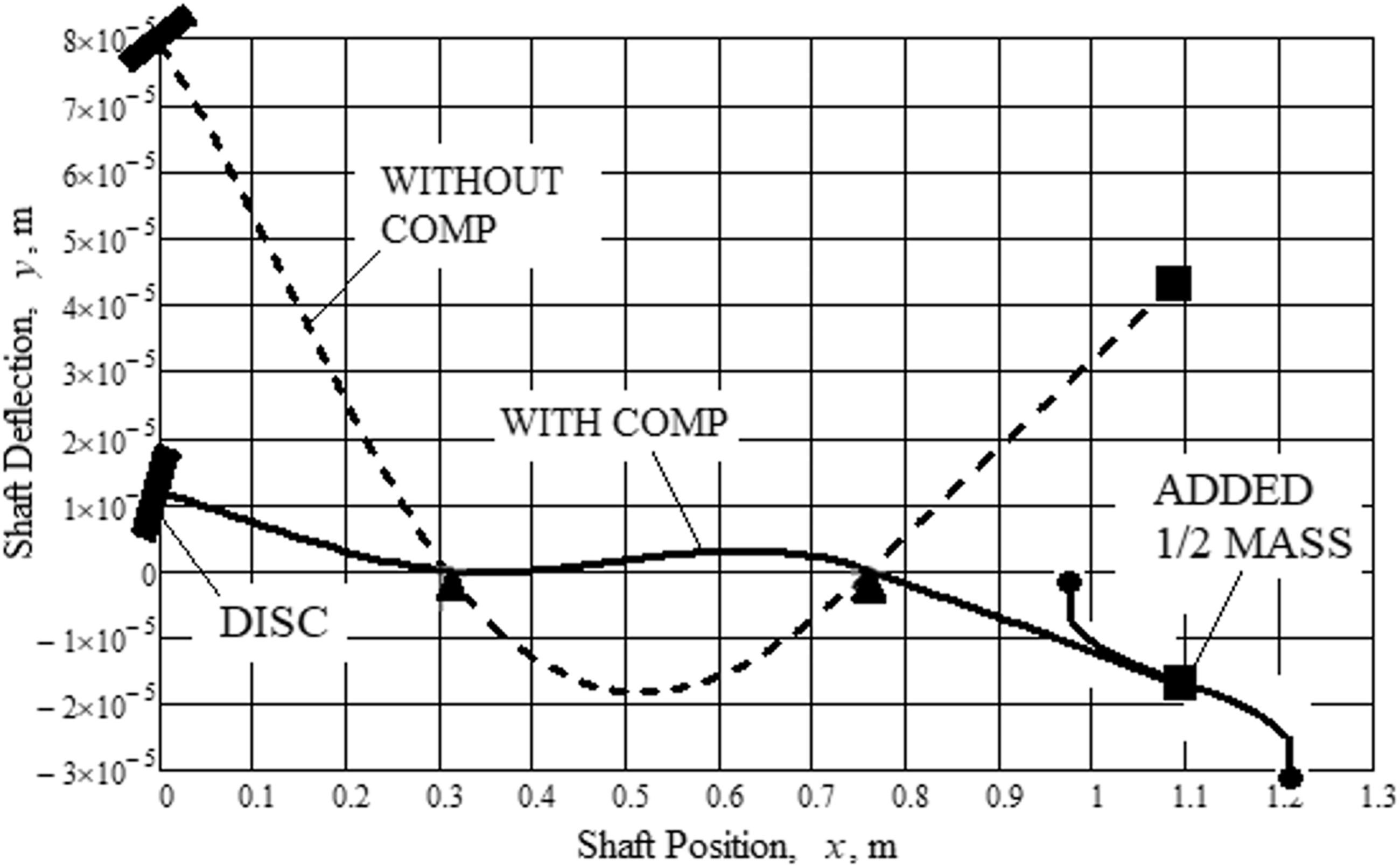
Shaft deflection profile, with and without compensation at 12,500 r/min.
The figures show that external application of balancing sleeve methodology is feasible for shafts with large overhung discs, thus enabling considerable reductions in disc deflections to be achieved, especially at higher operating speeds. It is also apparent that the dynamic requirement of encastre simulation to achieve optimum compensation, as defined in the earlier work by Knowles et al., 15 has been met for the portion of the shaft supporting the overhung disc, since the shaft slope at the first bearing is approximately zero.
Conclusions
This study formulated the design/advantages of a novel reactionless balancing sleeve with the capability of reducing the deflections of high speed, flexible shafts, without the imposition of bearing reaction loads. It enables reaction loads to be adjusted at the balancing stage of a fully assembled shaft on a conventional, low speed, balancing machine and shaft deflection to be separately controlled during a commissioning operation, at say, 60% full operational speed, and before any excessive deflection/abradable seal wear occurs on machines with bladed shafts, for instance; thereby preventing further enlargement of seal diameters/excessive fluid leakage so as to increase volumetric efficiency.
Further, the study clearly shows the practicality of applying compensating balancing sleeves to a machine’s input or output shaft end, external to its housing/casing, so that the time/cost benefits associated with improved accessibility can be fully realized. It is also demonstrated that the benefits of encastre simulation apply to all types of flexible shafts.
Notably, the analysis doesn’t include any of the damping terms that exist in a real machine. These would of course normally produce angular rotation of the shaft imbalance, i.e. its heavy spot, relative to its deflection and may require correction during commissioning/service. Generally, the magnitude of phase variation over the operating speed range is small and can be accommodated by a suitable midpoint balance correction. However, in cases where this is not adequate it is necessary to adjust, either manually or automatically, its angular position. The reactionless balancing sleeves, as with those of the previous studies, would have a number of pre-machined tapped holes in their balancing rings for this purpose. It is notable that all balance correction is made by adjustment of the static position of the balancing ring’s mass centroid, eccentricity and angular position, and that this could easily be achieved by various means of remote electrical actuation. Hence the design lends itself to a system of automatic balance correction if required.
Footnotes
Acknowledgements
The work presented in this paper is supported by academic staff, School of Engineering, University of Lincoln, United Kingdom.
Declaration of Conflicting Interests
The author(s) declared no potential conflicts of interest with respect to the research, authorship, and/or publication of this article.
Funding
The author(s) received no financial support for the research, authorship, and/or publication of this article.