
Abstract
The objective of this work was to investigate how different joining techniques affect the level of damping in structures. Beams were constructed from four different joining techniques, bolting, riveting, adhesive bonding, and brazing by joining two lengths of steel each with a ‘U’-shaped cross-section. They were joined such that the edges of the ‘U’ overlapped to form a tube. The damping of each beam was determined by flexural vibration. The bolted beam had a series of bolts along its length. The effect of removing bolts was investigated. It was found that removing bolts increased damping. When bolts were removed successively from holes at the end of the beam, the damping increased more than when bolts were removed from holes in the middle of the beam. A further objective of this project was to investigate the effect of introducing penetrant between two surfaces. WD-40 was introduced between the contacting surfaces for the beams joined by mechanical fastening. The penetrant had the effect of increasing damping. This may be because the penetrant has the effect of increasing the relative displacement between the two beams, leading to greater energy dissipation. Introducing penetrant also changed the order of which beam had the greatest damping, with the bolted beam now having greater damping than the riveted beam. The effect of increasing bolt tension on the bolted beam was also investigated. When the beams were dry, increasing bolt tension reduced the damping, but when penetrant was introduced increasing the bolt tension increased the damping. A comparison between the damping properties from different joining techniques was made. The conclusions could be applied in industry by engineers constructing beams of a similar fashion.
Introduction
Damping, in both simple and complex mechanisms, has been an area of rigorous scientific study for many years. The drive to understand, model and, most importantly, accurately predict the potential mechanical damping in structures cannot be understated. Damping does not often relate to a single mechanism or mechanical property within a structure, so difficulties can arise. Unlike, say, mass or stiffness, it cannot often be directly ascertained without experimentation and analysis.
There are many damping mechanisms in engineering structures and components. Any process that converts mechanical energy into heat energy, acoustic energy, or other forms of energy can be a damping mechanism. The most significant damping mechanisms in structures are material damping and interfacial damping. Interfacial damping occurs most often at joints but can happen anywhere that two surfaces come into contact. Inherent material damping stems from complex molecular interactions within the material. Therefore, the material type, its manufacture and finish are all factors. It has also been shown that degradation and internal cracks in a material also contribute to material damping.1–4
A desired level of damping is often required in engineering structures and this is often achieved with external systems. Damping is becoming increasingly important in engineering systems, as systems become more complex. For example, buildings are becoming taller and more flexible, and modern high-rise buildings may still oscillate excessively during windstorms and earth tremors. The level of these oscillations may not be sufficient to cause structural damage but may cause discomfort to the building occupants. In these instances, the damping, stiffness, and strength of the buildings will be of paramount importance. This is also true for aeronautical structures. It is very important to understand the damping inherent in, for example, communications satellites, or multi-component space structures. In the vacuum of space, there is no acoustic radiation damping to reduce vibrations, and periodic deflections in the structure can cause fatigue stresses. In the case of a communications satellite, cyclic oscillation can cause Doppler shift and location problems for a receiving satellite dish on earth. As a result, the more known about the intrinsic damping of substructures, the better. Damping is also very important in limiting vibration during the launch process.
There are many well-known examples where unexpected dynamic vibratory properties in structures have caused negative outcomes. Two obvious examples are those of the “Millennium Bridge” in London, where the unexpected driving force from pedestrians caused the bridge to sway quite alarmingly, and that of the Tacoma Narrows bridge which failed catastrophically when high winds caused a resonant vibration within the bridge structure.
Friction is present in almost every mechanical system and it occurs when two contacting surfaces are in relative motion. Friction or ‘Coulomb’ damping is the dissipation of vibrational energy into heat due to elastic and plastic stressing as well as abrasion due to relative movement between two surfaces. The laws of friction are based on observations and experiments by Da Vinci, Armontons, and Coloumb.
The friction force is proportional to normal load. The friction force is independent of contact area. Friction is independent of relative velocity.
Modelling friction is notoriously difficult because there are many factors that can affect it such as:
Contact geometry, topology, and surface roughness. If the two surfaces undulate, the asperities may interlock as the surfaces come together, requiring a higher “breakaway” force. The breakaway force is required to completely overcome friction. Material type, hardness, and wear rate. Protrusions or “asperities” of a harder surface act as an abrasive resulting in debris. Lubrication. Friction is affected by the presence of surface oxides and lubricants.
There are many phenomenological and non-phenomenological models, which can be used to model friction more accurately. Important models incorporate a combination of pre-sliding displacement, the Stribeck Effect, the LeGru model 5 and the Armstrong-Hélouvry et al. seven-parameter model. 6
Most studies on energy dissipation in joints consider a single bolted joint in a vibrating system. Ma et al. 7 sought to identify the dynamics of bolted joints by comparing two beam systems for which the only difference was a single bolted joint at the mid-span of the beam. Theoretical models were prepared for the beams by augmenting Bernoulli-Euler beam theory with an extra term, a local force operator that would mimic the dynamic effects of the joint. Frequency plots showed the joint non-linearity had a softening effect on the first three modes as the joints became progressively looser. This non-linearity was credited to impacts between the shaft of the bolt and the beams due to progressive joint loosening. However, the mode shape itself was not greatly affected in the lower modes.
Gaul and Bohlen 8 measured the dependence of the reaction force of a bolted joint on the relative displacement of the joint. The results revealed the relationships between hysteresis, the amplitude of the excitation force, and the mean contact pressure. The study concluded that, in the micro-slip regime, the influence of gaps and viscous damping could be neglected. The joint stiffness and slip force of an elastic Coulomb element were evaluated. While there was no significant shift in the natural frequencies, the damping was found to be significantly increased at higher excitation levels. Later work by Gaul and Lenz 9 and Gaul and Becker 10 extended this approach, but the theory was fitted to the experiments by choosing a suitable coefficient of friction, usually between 0.2 and 0.4.
In bolted lap joints, high normal loads are applied by connecting bolts to limit relative movement between components. The normal reaction pressure between the two surfaces is not uniform and the part of surface that has a lower reaction pressure may slip, while the part of the surface with a high reaction force may stick. Slip may not therefore occur over the whole of the contact area; this effect is called micro-slip. Kess et al. 11 used the Dahl and LeGru models to simulate the behaviour of a joint using finite element analysis. Their experiment involved using washers of different areas and normal contact pressure to observe the effect on damping. It was found that damping is a function of the bearing area over which micro-slip can occur. The level of damping is a function of the stress distribution in the bearing surfaces, and when friction is modelled as Coulomb Friction, then the amount of energy dissipated is proportional to the normal force. It was found that the LeGru model gave a better prediction than the Dahl model due to its incorporation of the rate-dependent Stribeck effect.
The effects of joints with multiple bolts have been studied by many authors. Much work went into understanding the intensity of pressure surrounding a single bolt, allowing the cumulative effect of multiple bolts to be predicted. Ziada and Abd 12 found that the pressure distribution at the interface of bolted joints is parabolic in nature and has an influence zone 3.5 times the diameter of the bolt. This circle of influence is independent of the tightening torque applied. Nanda and Behera 13 studied the mechanism of damping and its theoretical evaluation for layered and jointed cantilever beams with a number of equi-spaced connecting bolts. Building on the work of earlier studies, a mathematical model was derived to predict the damping in multi-layer cantilevered beams. Nanda and Behera predicted the damping ratio in a layered jointed structure by equating the energy dissipated due to relative dynamic slip between the interfaces and the total energy introduced into the system. The theoretical predictions rested on the assumed pressure distribution caused by bolting over the length of the beam, and the value chosen for the coefficient of friction. They found that the damping decreases with an increase in the bolt-tightening torque. Shigley 14 stated that the torque on a nut and the axial bolt load were proportional.
Goyder et al. 15 bolted two steel beams together with single bolts at the nodal positions for the first flexural mode of vibration. They found that an increased vibration amplitude caused a reduction in frequency (softening characteristic) and an increase in the damping. For the configuration tested, they did not find a strong correlation with bolt torque and attributed this to the receding contact predicted by Hills et al. 16 which appears as a gap between the interfacial surfaces separating the beams. Sun and Liao 17 used the finite element method to predict the damping of a flexurally vibrating beam consisting of two bars connected by a double strap secured with 12 bolts. They measured the coefficient of friction using an inclined plane and used this value [0.13] in their FE calculations. They found that the damping decreased as the bolts were tightened from 2 to 8 Nm, although the natural frequencies changed very little. Zhen Zhang et al. 18 modelled the dynamic responses of bolted composite structures using the elastic/viscoelastic correspondence principle. The complex contact moduli of the uneven interfaces of the joints, featuring multi-asperity contact at the micro perspective, were derived using the fractal contact theory. The damping and stiffness of the composite specimens were solved within ABAQUS software using the complex eigenvalue method. The damping ratios of the joints decreased, while the resonant frequencies increased by when the bolts of the joints were adjusted from fully loose to fully tightened.
There has been much work into controlling the interfacial slip of joints to achieve a specific level of damping in a structure, particularly by Beards 19 and by others since. The drawbacks of interfacial slip damping, namely reduced static stiffness, fretting corrosion at the interfaces and, importantly, non-linear theoretical analysis, 20 have meant that it cannot be designed into a structure. Nonetheless, it can be a cheap method of damping that, if the joints are carefully located, will not greatly affect the integrity or stiffness of the structure. Joint damping of this kind is closely linked with fretting corrosion and can exacerbate fatigue problems. It has been found that certain surface treatments are desirable (for example, cyanide hardening). However, in structures, it is often found that macro slip has the greatest potential for energy dissipation. For example, it was found in cantilevered beams 19 that the optimum energy dissipation is obtained by producing a slip amplitude between the contacting surfaces that is 50% of the undamped displacement amplitude. This was found by using both experimental evidence and simple linearised analysis, using an equivalent harmonic force to model the friction force.
Bournine et al. 21 examined the use of dynamic friction within a bolted structure to improve the damping properties of the structure which consisted of two steel beam-columns bolted together, allowing dynamic friction to occur at the interface. They analysed the behaviour of the structure and the effect of friction on its dynamics and derived an analysis of the energy dissipation in the structure by means of friction and the optimization of the bolt tension. The theoretical analysis gave very close agreement with the experimental results, and the effective damping of the structure was increased by a factor of approximately 10 through the use of dynamic friction.
The effects of combining bolting and adhesives as methods of increasing strength, durability, etc. of joints have also been studied. Originally, this technique was considered useful for repair and improvement of damage tolerance. 22 However, work by Kelly 23 has looked at the distribution of load in these structures, and the effect that changing various parameters could have. The study compared hybrid bolted/adhesive single lap joints to adhesively bonded single lap joints in both experiment and FEA software. Both the FEA model and the specimens used a neat fit between the bolt and the hole, as this would allow for the greatest load to be carried by the bolt. It was found that the load transferred by the bolt was increased with increasing adhesive thickness and adherend thickness to be carried by the bolt. It was found that the load transferred by the bolt was increased with increasing adhesive thickness and adherend thickness.
Investigations into the dissipation of energy by friction in joints cover a wide range, from joint contact mechanics through to dampers on buildings. To review this work fairly would occupy at least one book. There are mathematical treatises and some that are only experimental. Some try to combine theory and experiment with varying degrees of success. A weakness is that few authors are skilled in the accurate measurement of damping. It is easy to produce numbers, but there is little evidence that the numbers are valid. Many authors use the viscous damping ratio because this is convenient to use mathematically, but there are problems if the damping is hysteretic or due to friction. For large values of damping, more than 0.05, there are problems of non-linearity, while values less than 0.001 require skill and experience. LE Goodman told the senior author (RDA) when he was a postgraduate that “in damping, the lowest value wins”. It is therefore important to calibrate any damping measurements by using a very low damping material as the baseline. If the lowest measurement attained is higher than what should be expected from the low damping material, the apparatus and test methodology need to be improved or discounted.
From the above, it can be seen that damping in bolted and similar joints is important. However, it is difficult to make predictions of damping levels in real structures no matter what level of sophisticated mathematics is used. Phenomenological experience is therefore of some use in guiding engineering designers into what might be expected, and this is the intention of the work presented in this investigation.
Experimental programme
Specimens
A range of thin-skinned mild steel beams was fabricated. These beams were chosen so that they could be joined in several different configurations:
Bolted Brazed Adhesively bonded Riveted
This selection represents the most commonly used methods of joining in industry. The specimens were constructed to the dimensions shown in Figure 1.
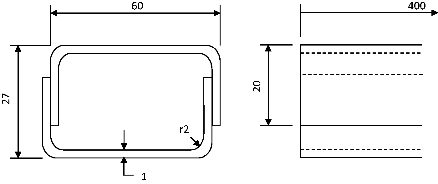
Test specimen (dimensions in mm).
The blanks for the beams were cut from mild steel sheet before being folded to the required shape. All the specimens were cleaned with acetone, and the specimen to be bonded was grit blasted to remove surface contaminants. Access to the inside was difficult once the beams were assembled, so nuts were bonded to the inside of the bolted beams with cold curing epoxy resin. Standard 3 mm aluminium rivets were used to join the riveted beam. The arrangement of the bolts and rivet holes is shown in Figure 2. The only exception to Figure 2 is the brazed beam; this was constructed as a control specimen, to give the minimum amount of damping possible. As it was very difficult to braze the beam successfully using two U-shaped blanks, the brazed beam was folded into a tubular shape; a small overlap being left where the beam was to be joined.
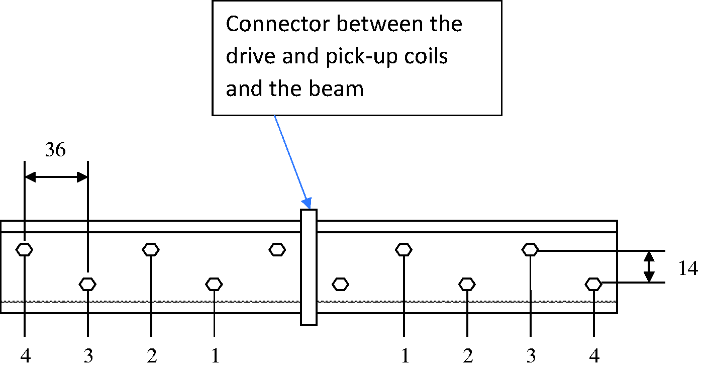
A schematic (not to scale) diagram of the bolt layout and numbering system. The two bolts not numbered were never removed. Dimensions in mm.
Araldite AV119, a one-part heat curing epoxy, was used to construct the bonded beam with a 0.9 mm glue line. Small mild steel inserts were used to control the bond-line thickness and four of these were placed along the beam at regular intervals. Adhesive was spread evenly across one of the faces to be bonded before the insert was placed into the adhesive. The beam was assembled using a template and clamped, keeping consistent pressure across the joint. The beam was cured according to the guidelines for AV119, at 120°C for 1 h in a thermostatically controlled oven.
Damping apparatus
For useful damping measurements to be made, the apparatus used has to provide sufficient dynamic excitation while having minimal effect upon the damping of the specimens being examined. Cantilever beams have been used extensively for the determining the dynamic properties of simple structures. However, extensive in-house experience has shown that the damping measured by using the cantilever or any other clamped end fixtures is highly dependent on the clamping conditions, as it is almost impossible to eliminate slippage in the grips. A free–free beam supported at the nodal positions reduces extraneous losses and is by far the best arrangement. For a beam vibrating in flexure in its first free–free mode, the antinodes are at the two ends and the middle. Such a beam can be carefully supported at its nodes which lie at about the ¼ and ¾ positions for a uniform beam. Impulse (hammer) excitation was avoided, as it excites too many modes which have to be filtered out causing uncertainty in in the end result. Also, it is difficult to excite other than low amplitudes without large impacts which can cause full body motion a.
The use of an electrodynamic shaker connected to the structure would also lead to a significant increase in the levels of damping measured, despite providing more than adequate excitation. Therefore, it was decided to attach the coil to the beam and to use a large electromagnet attached to a heavy platform to provide the magnetic field. The rig used is as described by Adams and Bacon 24 and is shown schematically in Figure 3.
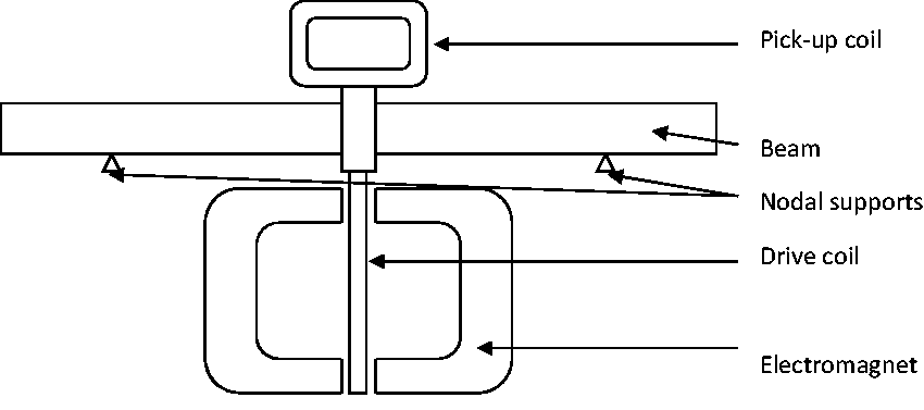
Schematic diagram of the damping apparatus.
The beam was clamped between the pickup coil and drive coil. The pickup coil moves through the field of a fixed pole magnet, generating a voltage which is directly proportional to the velocity. Accelerometers were discounted for use as they required trailing wires, which could introduce damping.
Two methods were used to record the results; the first was to measure damping by the half power point method and the second to measure the logarithmic decrement. The half power point method is time consuming, while the logarithmic decrement could be determined automatically via Matlab. The two methods gave almost identical results, so the logarithmic decrement was chosen for convenience. The position of the supports (nodal points) was also critical. These were located by using a microphone which was moved along the beam vibrating in its first mode. This was repeated before each test, as there were small variations in nodal positions because of the differing masses of each beam. The coils were then carefully located in the air gap between the poles of the respective magnets. To carry out a test, the system was tuned to resonate at about 800 Hz. The excitation was then cut by instantaneously switching off the current to the drive coil and the DC current which provides the magnetic field and recording the vibration level measured by the pick-up coil as a function of time.
Figure 4 shows a comparison between the two methods used for the calculation of the damping ratio of a riveted beam. The data for the logarithmic decrement were produced from one decay capture (the data shown are from one of six well-correlated captures), while several readings needed to be taken for the half-power method to produce this graph. There was good correlation between the two methods; subsequent refinement of the MATLAB analysis programme reduced the spread in results from the logarithmic decrement method further. The results from the log-dec method were transformed from the time to the amplitude domain.
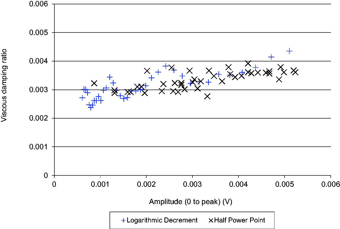
A comparison of results from half power point and logarithmic decrement methods
There were several advantages to utilising the logarithmic decrement method. The capture was displayed instantly on screen, and the waveform studied for uneven decay, transient frequencies and excessive noise. If any of these were seen, the set-up could be adjusted and the experiment repeated. Analysis of the data via MATLAB was very quick, and it could be exported to Excel to plot graphs. The half power method was much slower so was only used a check.
Results and discussion
Effect of bolt tension (tightening torque)
The effect of bolt torque on the dissipation within a beam joined with multiple bolts is shown in Figure 5. As the torque in the bolts is increased, the damping decreases. This fits well with theory. As the normal contact pressure increases, the stick zone increases also which prevents the relative movement of adjacent faces, thereby reducing the dissipation.
Damping vs. amplitude for a bolted joint at different torques
Increasing the torque in the bolts has a secondary, but small, effect of increasing the overall stiffness of the beam which, as a result, increases the natural frequency of the first mode. If it were possible to provide a uniform pressure across the entire overlap, so preventing any slip, the damping of the specimen would approach the damping of a tube of similar dimensions.
Effect of removing bolts
Bolts were removed to see the effect on the damping of the structure. The bolts were removed in a symmetrical manner until the only bolts remaining were the central bolts. These needed to be left in place to maintain a solid connection to the electromagnetic excitation/pick-up coils. The numbering system for the different bolts is shown in Figure 2.
The results of removing the bolts, first from the inside out then from the outside in are shown in Figures 6 and 7, respectively. The damping when all the bolts are present and when they have all been removed (except the pair nearest to the mid-point) are identical for both cases (as would be expected).
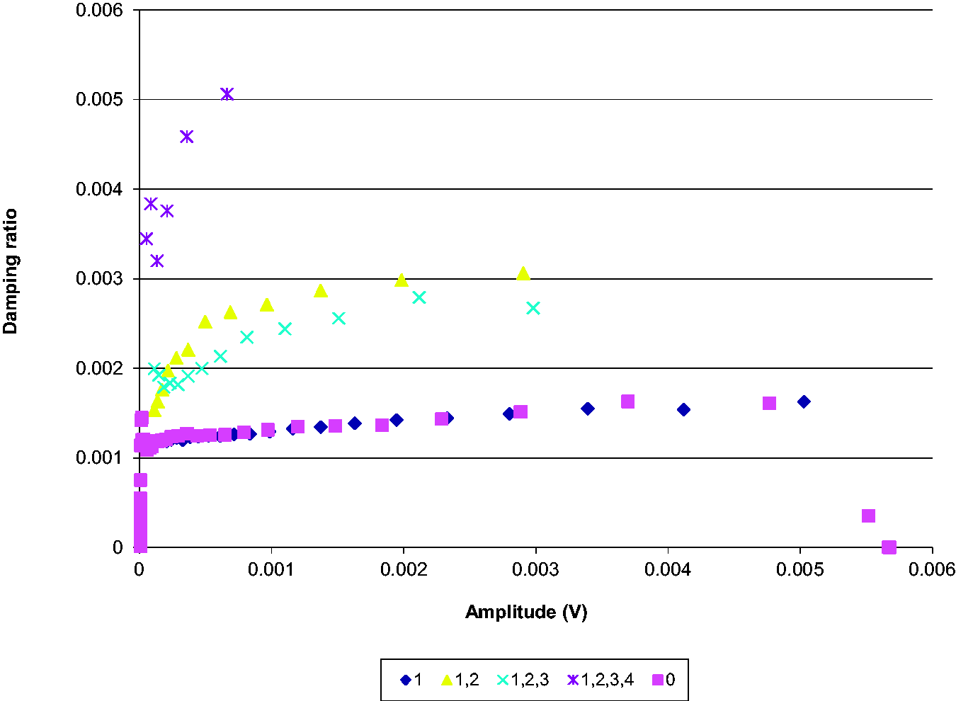
Damping vs. amplitude while removing bolts from the inside.
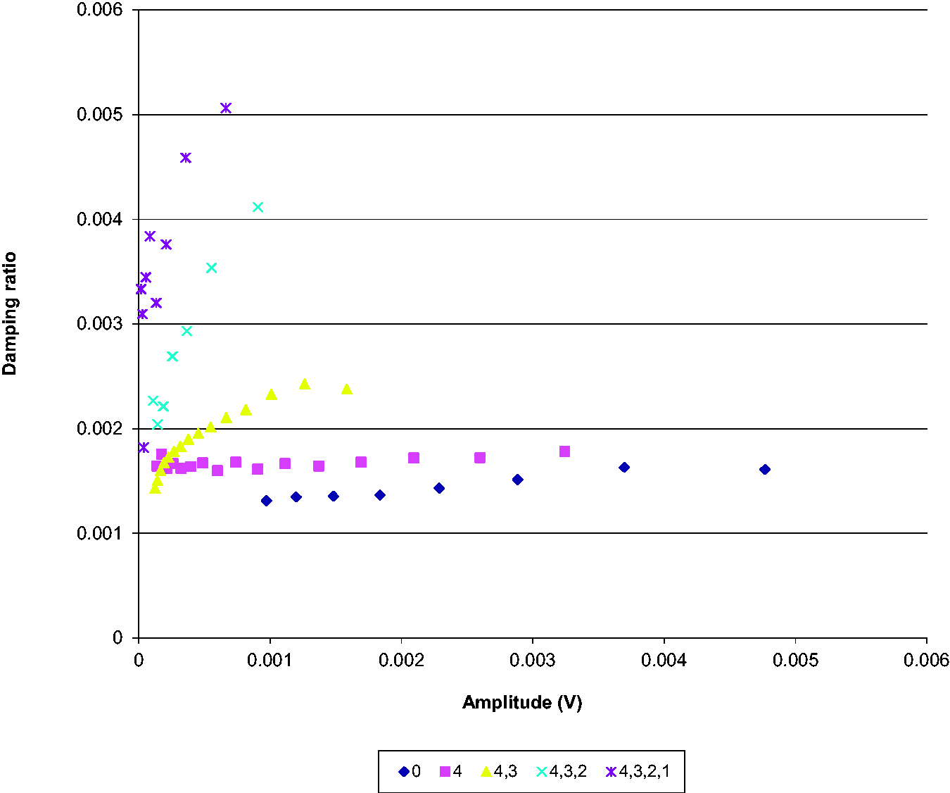
Damping vs. amplitude while removing bolts from the outside.
Removal of bolts from the inside
In the case where the first set of bolts (1) was removed, there was no significant increase in damping. Relative movement of the two faces was small, as they continued to be constrained by bolts on either side. The removal of the next set of bolts (2) showed quite an increase in the damping of the beam. The slip that could be achieved between the two faces continues to increase, as more bolts are removed from the beam, and the length of beam unconstrained by fixings increases. While both ends of the beam continue to be constrained by a set of bolts (4), the two sections will continue to vibrate in harmony. When removed, the ends could vibrate with different magnitudes, resulting in maximum slip.
Removal of bolts from the outside
When the bolts on the beam were removed consecutively from the outside-in, the damping effect was much more visible. The first bolt to be removed only increased damping a small amount. Because of the relatively short, stiff nature of the sections which were unconstrained, inertial effects causing the sections to vibrate at slightly different amplitudes would be small. As the length of the unconstrained section increased these effects become more and more pronounced, and where the sides came into contact there would be more and more dissipation. The effect of removing the bolts on damping is seen to be more pronounced in Figure 7. In addition to the difference in transverse vibration, unconstrained by the outer bolts, there would be differences in the lateral motion of the upper and lower sections. Where these were unconstrained, assuming the individual sections vibrated around their centroids and that both sections had similar mode shapes, then the tops of both beams would be in tension the bottom would be in compression.
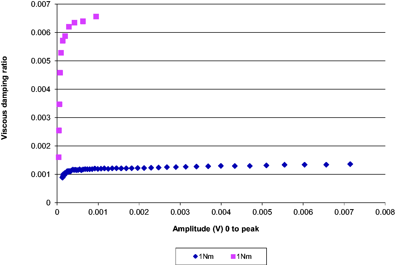
Effect of penetrants on the damping
Introducing a penetrant (e.g. WD40) to the beam joint will reduce the friction between the two surfaces. A reduction in friction means, for the same normal contact force, there will be a decrease in the stick zone and an increase in relative movement. However, the energy dissipated per unit distance slip will be reduced. The results of the experiment are shown in Figure 8; they show a low level of damping before the penetrant is introduced and a higher level afterwards for both levels of bolt torque. The results agree with those obtained previously for a plain bolted beam, that the higher the bolt torque before the penetrant is introduced the lower the damping. After the introduction of the penetrant, the bolt with the 3 Nm of torque seems to give higher damping than the bolt with just 1 Nm of torque. This seems logical, if the penetrant allows relative movement of the two faces and the coefficient of friction is the same, so more energy is dissipated where the normal contact force is the highest.
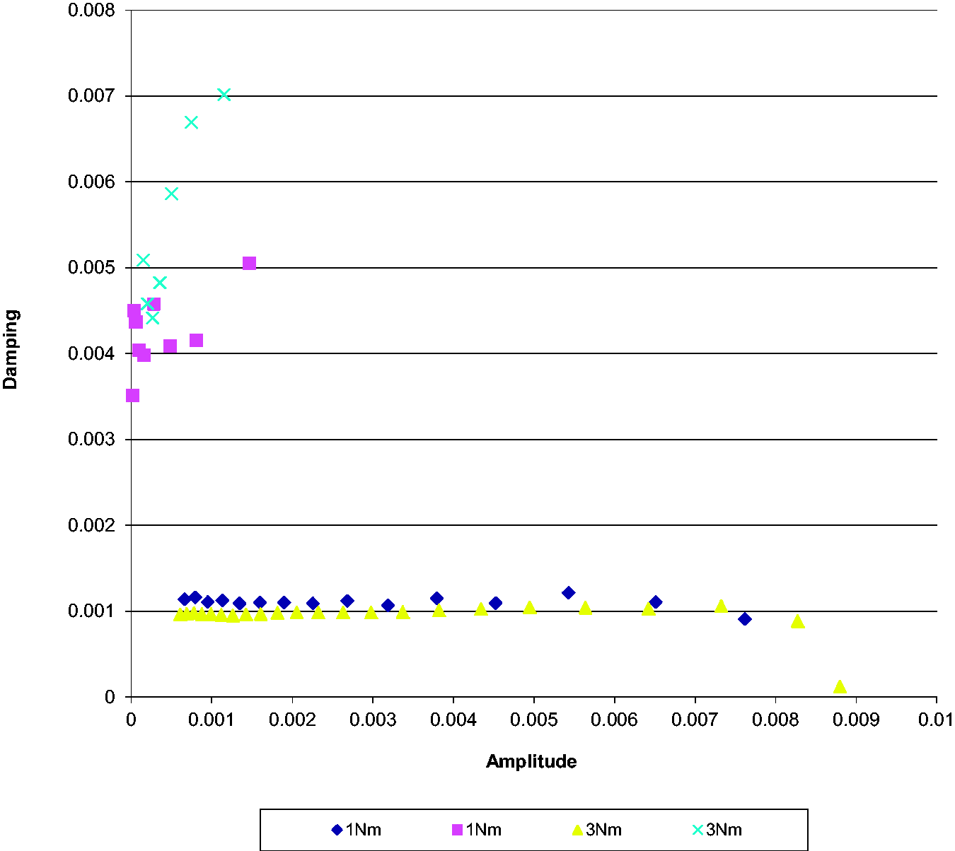
The effect of introducing a penetrant on the damping in a bolted beam.
The effect of water on the damping of the bolted specimen was also investigated. Water is much more likely to seep into an engineering structure than WD40 or an equivalent penetrant. Burst water pipes within a building, condensation or rain are all everyday occurrences. The results from this test are shown in Figure 9. As can be seen, the effects are very similar to the introduction of WD40 into the joint. Low damping is observed in the joint in its dry state, with an increase of three times upon the introduction of the water. Both water and WD40 are low viscosity fluids, and easily penetrate between the two surfaces. It would be unsurprising to find that other low viscosity fluids would have similar effects upon the damping.
The effect of the introduction of water on the damping of a bolted beam.
Similar results were found by Flitcroft25 when the effect of a dye penetrant on the dynamic properties of cracked GFRP and CFRP specimens was considered. He found that in large cracks, where the constraining effect of the surrounding material was relatively small, the overall damping increased, up to the point that total crack mobility was approached.
Comparison of different joining methods
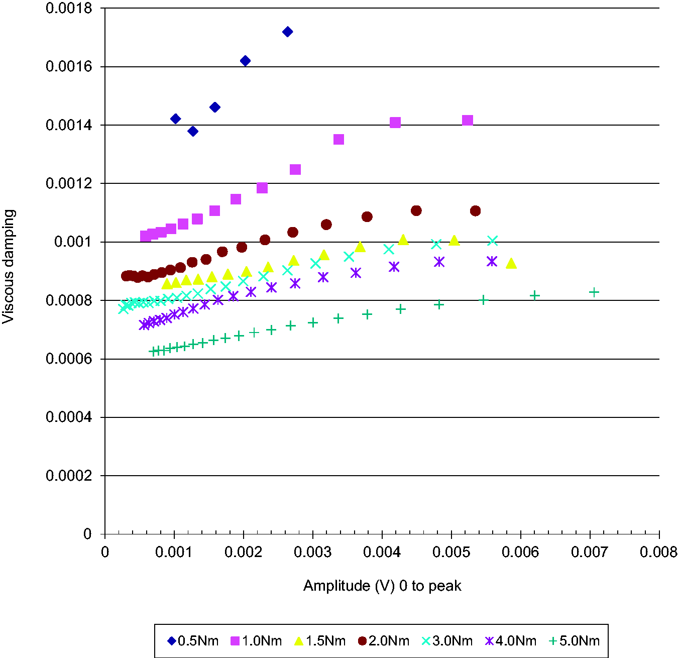
The results for each of the beams tested are shown in Figure 10. As would be expected, the damping for the brazed “control” beam is the lowest. This beam is entirely reliant upon material and air damping for energy dissipation (maximum viscous damping ratio of 0.7E-3), with no surfaces rubbing or moving adjacent to each other. The adhesively bonded beam also exhibited very low damping (maximum viscous damping ratio of 0.9E-3); AV119 is a stiff structural adhesive and even with this relatively thick glue-line was poor at dissipating energy which is dissipated mainly by shear within the adhesive.
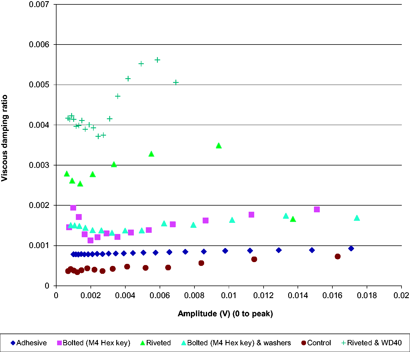
Damping ratio vs. amplitude for several different beam types.
The bolted beams had approximately twice the damping of the brazed and adhesive beams. Two “types” were tested, one a plain bolted beam and the other a beam bolted with washers to separate the adjacent surfaces by 0.5 mm; both gave similar levels of damping (with a maximum of 1.90E-3 and 1.77E-3 respectively). The contact area between the adjacent faces is limited to the size of the washers, so it is unsurprising there was some reduction in damping.
The riveted beam was similar to the bolted beams in construction with both having the same layout and bolt/rivet spacing. Despite this, the riveted beam did not seem to have the same integrity as the bolted beam, presumably because the interfacial pressure due to the riveting process was much less than when using the bolts. The rivetted beam was difficult to excite in the first mode and it was possible to hear rattling noises due to relative motion between the steel beam sections and the rivets.
Once experiments had been finished on the riveted beam in its dry state, it was sprayed with the commercially available penetrant WD40. The WD40 was applied liberally along the joins where the faces met and left to soak for 5 min. The damping then increased to similar levels as the bolted beams which had had the same treatment.
Conclusions
The objective of this project was to investigate how different joining techniques affect the level of damping in structures. Beams were constructed from different joining techniques, and the damping of each beam was measured as a function of amplitude in free–free flexural vibration. In order of greatest damping, the different joining techniques were:
Riveted Bolted Adhesively bonded Brazed
For a bolted beam, it was shown that increasing the bolt tension reduced the damping because it increased the stick zone and decreased the slip zone.
It was found that removing bolts increased the damping. When bolts were removed successively from holes at the end of the beam, the damping increased more than when bolts were removed from holes in the middle of the beam.
A further objective was to investigate the effect of introducing a penetrant between the surfaces. WD-40 was introduced between the contacting surfaces for the beams joined using a mechanical fastener. The penetrant had the effect of increasing damping. This may be because the penetrant has the effect of increasing the relative displacement between the two beams leading to greater energy dissipation. Water had a similar effect. Introducing penetrant also changed the order of which beam had the greatest damping, with the bolted beam now having a greater damping than the riveted beam.
Footnotes
Declaration of conflicting interests
The author(s) declared no potential conflicts of interest with respect to the research, authorship, and/or publication of this article.
Funding
The author(s) received no financial support for the research, authorship, and/or publication of this article.