
Abstract
The electromechanical planetary gear system has high work efficiency and long service life, but factors such as heat, wear, and electrical signals can affect the transmission performance of electromechanical planetary gears. This article comprehensively considers factors such as temperature, tooth surface wear, lubrication, current and voltage, damping ratio, etc. Based on the principle of thermal deformation, Archard wear model, and equivalent circuit principle, a dynamic model of electromechanical planetary gears is established. The existing literature has not comprehensively analyzed the effects of temperature, wear, and electrical signal changes on the nonlinear characteristics of electromechanical planetary gear systems. The results show that when the motor current is between 7 A and 18 A and the voltage is lower than the rated voltage, the system is in a stable state; as the temperature rises, the system tends to stabilize; the gear wear exceeds 30 μm, and the bifurcation characteristics of the system are more pronounced.
Keywords
Introduction
The utilization of motors as the primary energy source for propelling gear transmission systems is a conventional electromechanical coupling arrangement. The aforementioned technology finds extensive application in the aerospace sector, electrified transportation industry, natural resource gathering and production industry, and wind power industry. Asynchronous motors, being a prevalent kind of motors, hold significant importance as integral constituents of motion control systems. Hence, the scientific value lies in the connection of asynchronous motors with gear systems. The stability demands for electromechanical systems have grown in tandem with industrial advancements. The stability of gear systems can be influenced by a range of nonlinear factors, which can result in unstable and chaotic motion. Consequently, an examination of the chaos and bifurcation properties of the system can contribute to enhancing the stability of electromechanical systems and facilitating the prompt and precise identification and diagnosis of system malfunctions.
Electromechanical planetary transmission systems are widely used in many fields, and many scholars have studied the nonlinear characteristics of electromechanical coupling systems and planetary gears. Feki et al. 1 developed a model of an asynchronous motor gear system, analyzed and simulated the model's dynamic performance, and determined that defects can be identified by the signal waveform of the stator current; Tomasz Szolc et al. 2 developed a coupling model that integrates rotating equipment and asynchronous motors. This model was built upon the dynamic coupling between the rotating and driving motors. Subsequently, the researchers performed simulation analysis on the developed model. The study findings established a correlation between the variations in electromagnetic current between the stator and the rotor and the dynamic properties of the mechanical system; Bilal EI Yousfi et al. 3 employed the technique of centralized parameter modelling to develop an electromechanical coupling model for an induction motor planetary gear system. The meshing stiffness excitation was determined by the utilization of a novel potential energy approach. The model was subsequently analyzed employing vibration and electrical measurement techniques. Furthermore, a refinement method for the stiffness curve was validated by means of experimental measurements; Bai et al. 4 developed a network model for squirrel cage asynchronous motors, incorporating nonlinear magnetic conductivity. Additionally, they formulated a pure torsional dynamic model specifically for planetary gears. The researchers then proceeded to investigate the impact of various factors on the system; Yi et al. 5 developed a dynamic model for electrically powered multi-stage gears. They investigated the interplay between the gear system and the motor, and examined the impact of electromagnetic effects on the intrinsic vibration characteristics of the gearbox; Zhang et al. 6 successfully developed a model for a wind turbine electromechanical coupling system and conducted an analysis to determine the impact of system parameters on both the dynamic response and current harmonics. The findings of the study indicate that there is a clear correlation between mechanical characteristics and the motion period of the generator; Cavalca et al. 7 employed the finite element approach to examine the impact of the support structure on the dynamic response of the rotor bearing system; Chang-Jian et al. 8 conducted an analysis on the dynamic behavior of a gear pair system situated on a rotor bearing. The system was found to exhibit significant nonlinear effects, including nonlinear suspension effect, nonlinear coupled stress liquid film force, nonlinear friction force, and nonlinear gear meshing force. The researchers examined diverse manifestations of periodic motion, subharmonic motion, and chaotic motion across varying bifurcation parameters. The simulation findings demonstrate that the gear rotor bearing system displays significant non-periodic motion in the presence of these nonlinear effects; Khabou et al. 9 designed a single-stage gear reducer system for a diesel engine while taking into account time-varying meshing stiffness. They then analyzed the dynamic characteristics of the system's electromechanical coupling at various velocities; Liu et al. 10 investigated the impact of gear tooth shape error and electromagnetic features of the motor on the gear vibration characteristics within the context of a vehicle electromechanical coupling dynamics model; Chen et al. 11 developed a model that demonstrates the electromechanical coupling in a planetary gear system with a permanent magnet synchronous motor. The researchers also examined the impact of electromagnetic torque vibration and time-varying meshing stiffness of the motor on the dynamic features of the system; Wang et al. 12 developed a multi-stage transmission system utilizing planetary gears and driven by an electric motor for the purpose of investigating coal mining machines. They examined the influence of electromechanical characteristics on the system's performance, specifically focusing on the utilization of motor current to enhance dynamic performance and monitor operational conditions. Through this analysis, they were able to validate the efficacy of electromechanical dynamic modelling techniques; Feng 13 successfully used the motor current signal to diagnose the fault of the planetary gearbox in the induction motor planetary gearbox transmission system; Dai et al. 14 developed a nonlinear dynamic model for a transmission system of a large wind turbine. The model incorporated induction motors, three-stage planetary gearboxes, and motor vector control. The researchers then proceeded to investigate the dynamic response of both the gearbox blade subsystem and the motor; Gou et al. 15 adopted a simplified approach to describe the motor, wherein both the motor itself and its auxiliary components were treated as rotors. They further developed a gear rotor-bearing model that took into account factors such as tooth profile deformation and the time-varying meshing stiffness. The analysis focused on examining the bifurcation characteristics of the model; Ambarish et al. 16 employed both a lumped parameter model and a finite element model to examine the nonlinear dynamic characteristics of planetary gear transmission systems resulting from tooth surface clearance-induced tooth disengagement. The findings indicated that the lumped parameter model possesses the capability to accurately forecast the nonlinear dynamic attributes of planetary gear transmission systems; Kahraman et al. 17 developed a dynamic model for a spur gear transmission system with a single degree of freedom. Their findings revealed that the presence of load, damping ratio, and backlash can induce chaotic behavior and subharmonic responses within the system. Furthermore, they observed that the load has the ability to alter the impact state of the system; Vinayak et al. 18 established a nonlinear dynamic model of spur gears considering backlash, treating periodic excitation as a sine function, and analyzed the nonlinear characteristics of the system; Ding et al. 19 proposed a more flexible and practical numerical loaded tooth contact analysis (NLTCA) for high-performance spiral bevel gears and hypoid gears. 20 In order to distinguish the methods that focus on global system vibration effects in traditional rotor dynamics analysis, they also established a new semi analytical prediction model for high-speed and heavy-duty contact pressure of thin-walled spiral bevel gears in aerospace, and proposed a dynamic loading tooth contact analysis method that focuses on local contact zone loading contact effects. Finally, the correctness of this method was verified through numerical examples. 21 By utilizing an improved thermal electrohydrodynamic lubrication analysis, taking into account the entrainment angle and non-Newtonian fluid effects, the tooth surface meshing kinematics related to the entrainment and sliding states were determined through numerical loading tooth contact analysis; Simon et al. 22 introduced the geometry and kinematics of a worm gear pair based on hob generated worm gear teeth through a computer-aided loading tooth contact analysis method for different types of cylindrical worm gears, and studied and discussed the influence of tooth profile modification on tooth surface contact; Liu 23 developed a nonlinear dynamic model of gears that incorporated thermal deformation. They investigated the impact of temperature on the time-varying stiffness of the meshing and determined the trend of how temperature affects the nonlinear properties of planetary gears; Chen et al. 24 established the nonlinear dynamics of a gear pair with three degrees of freedom by analyzing the coupling effects of time-varying meshing stiffness, damping, bearing clearance, and additional parameters in accordance with the principle of thermal deformation. The investigation of the bifurcation diagrams of gears operating at varying frequencies and temperatures unveiled a multitude of temperature-induced effects on the dynamic properties of the system. An all-torsional dynamic model of planetary gears was developed by Shen et al. 25 , which incorporated gear wear and time-varying meshing stiffness and tooth side clearance. The model was based on the Archard wear model. The wear amount of straight bevel gears with backlash was determined by Brauer et al. 26 utilizing the Archard wear model; however, planetary gear wear was not analyzed. In summary, many scholars have taken the coupling system of electromechanical gear systems as their research object, but there has been no in-depth research on the nonlinear dynamic modelling and analysis of the effects of wear, temperature, and electrical signals on the chaos and bifurcation characteristics of electromechanical planetary gear systems under the action of electric thermal mechanical multi-field coupling.
A dynamic model of motor-planetary gears under electrical-thermal-mechanical multi-field coupling is established in this article. The model incorporates various fields of electricity, heat, and force that are coupled. Temperature effect, friction, lubrication, time-varying meshing stiffness, tooth side clearance, and comprehensive meshing error are some of the factors considered in the model. The fourth- to fifth-order Runge Kutta algorithm is employed to solve the dynamic program of the planetary gear. In order to investigate current and voltage signals, temperature fluctuations, the impact of wear and meshing damping ratio on the system's nonlinear properties, and other relevant factors, bifurcation diagrams, phase diagrams, and Poincare cross-sectional diagrams are utilized. The simulation outcomes contribute to the advancement of electromechanical planetary gear transmission systems.
Establishment of a dynamic model for a motor gear system under the coupling of electric, thermal, and mechanical fields
After the introduction of the motor system, the changes in motor torque will directly affect the planetary gear transmission system, thereby changing the nonlinear characteristics of the gears. The coupling of the motor and gear system makes the nonlinear characteristics of the planetary gears more abundant. As shown in Figure 1, the drive of a three-phase asynchronous motor will generate an electric field in the system, and the current and voltage of the motor will affect the nonlinear characteristics of the planetary gears; The effect of the force field will generate friction between the gear teeth, leading to tooth surface wear, which will affect the tooth side clearance and meshing stiffness of the planetary gear; The effect of the thermal field will cause changes in the system temperature, thereby affecting the tooth side clearance.
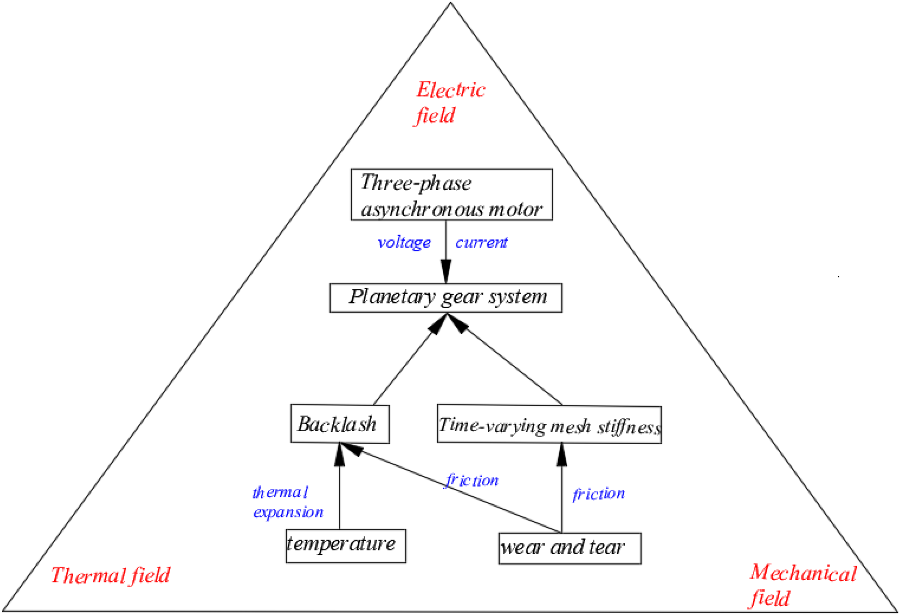
Simplified diagram of electric thermal mechanical multi-field coupling model.
Electromechanical coupling model of three-phase asynchronous motor gear system
Establish a three-phase asynchronous motor gear system model as shown in Figure 2:
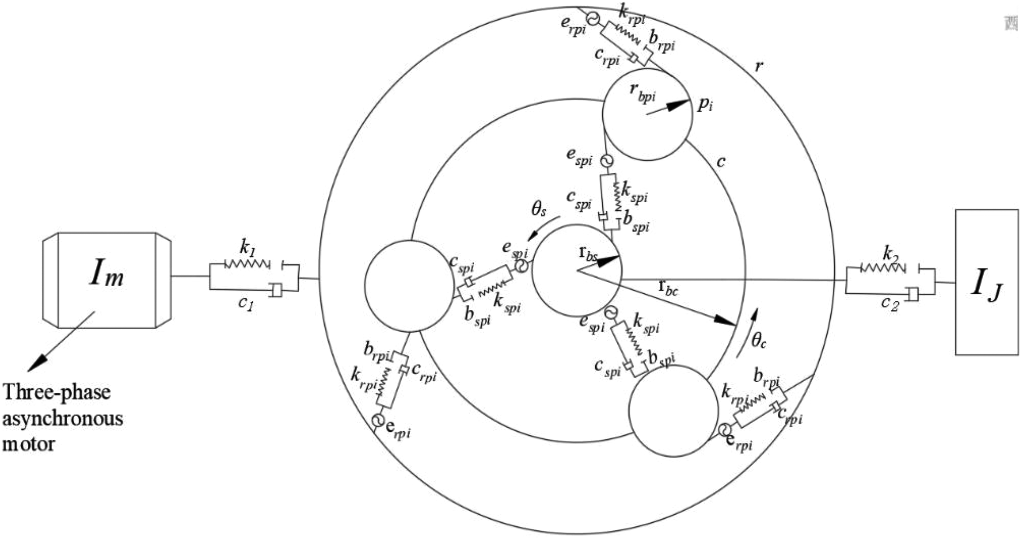
Model of three-phase asynchronous motor gear system.
The figure illustrates the damping and meshing rigidity of the inner ring gear of the planetary gear as denoted by krpi and crpi, and the planetary and solar gears as represented by kspi and cspi. k1 and c1 represent the torsional stiffness and damping coefficients of the load, respectively, while k2 and c2 represent the torsional stiffness and damping coefficients of the motor output shaft, respectively. The values of rs, rpi, rr denote the base circle radii of the sun gear, planetary gear, and inner gear ring, correspondingly; IM, IL, Ir, Ipi, Is signify the rotational inertia of the load wheel, driving wheel, inner gear ring, and sun gear, in that order; θM, θL, θr, θpi, and θs signify the respective rotation angles of each of the load wheel, inner gear ring, planetary gear, and sun gear.
Equivalent circuit model of three-phase asynchronous motor
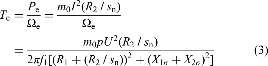
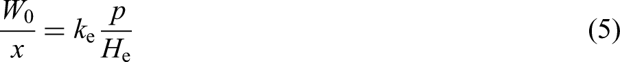
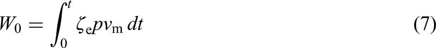
The model of a three-phase asynchronous motor is illustrated in Figure 3. The “T” type circuit model of a three-phase asynchronous motor is illustrated in Figure 4. A fraction of the electrical power P0 supplied by the power source is dissipated through the resistance of the winding, leading to stator copper loss PCu. A portion of the energy expended in the stator core is transformed into stator iron loss PFe. Consequently, the electromagnetic power transmitted to the rotor via the air gap on the stator side is as follows:

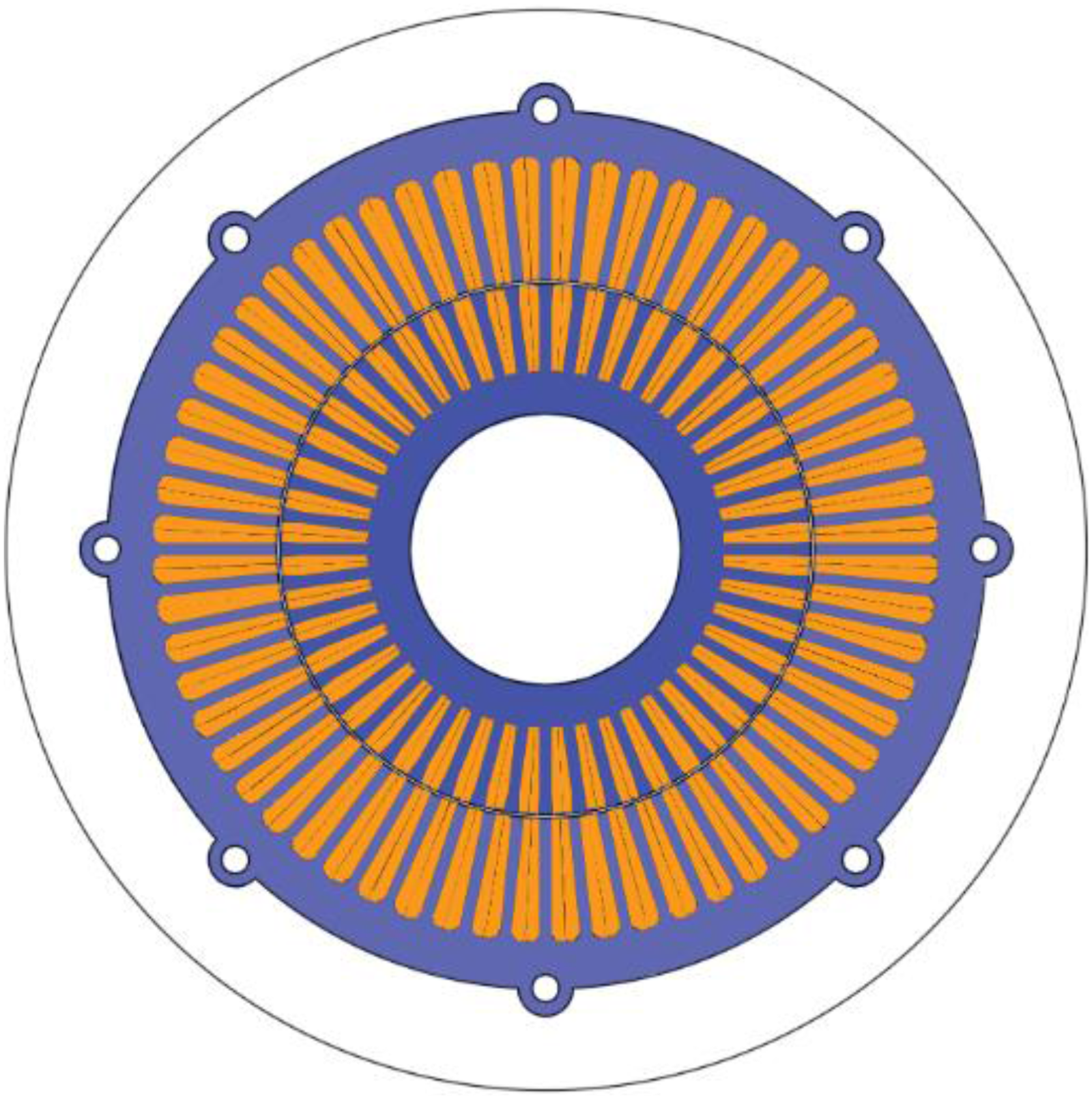
Model of three-phase asynchronous motor.
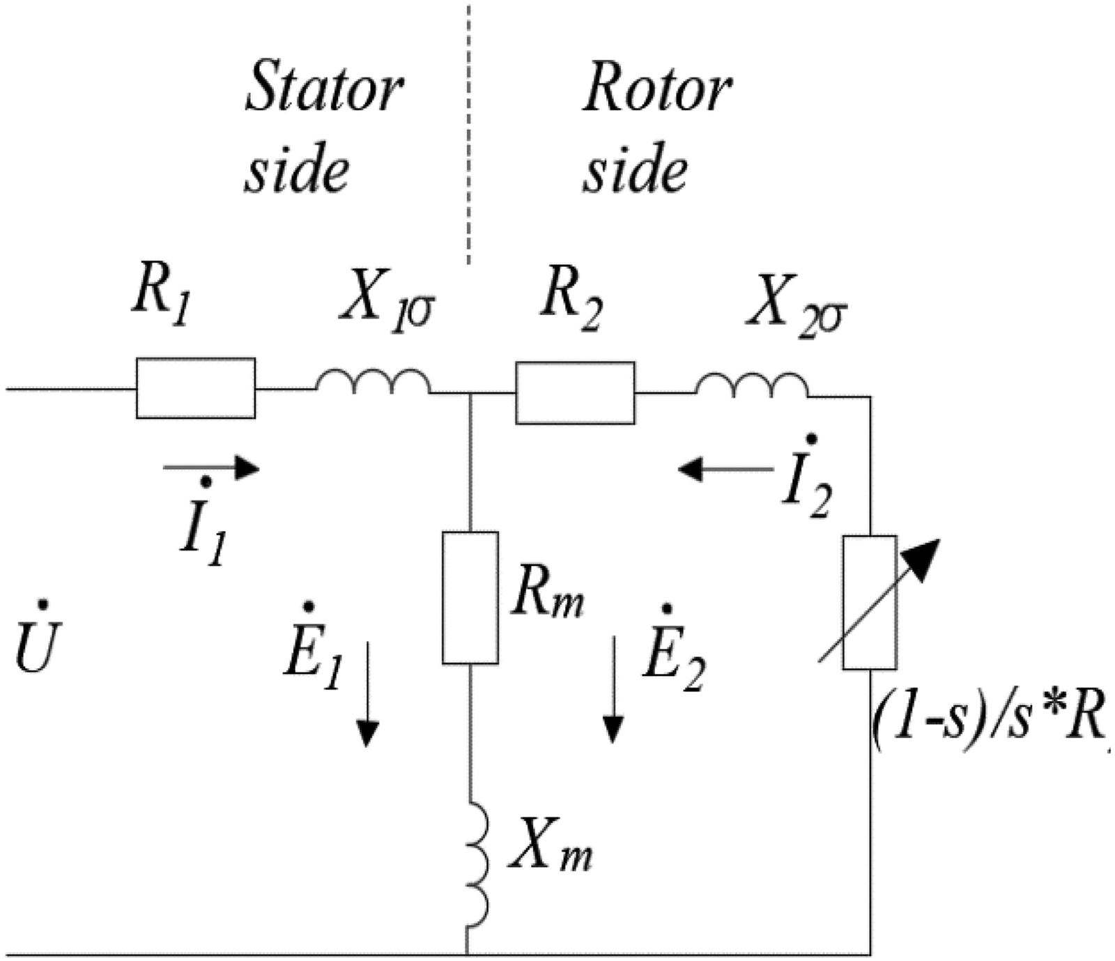
Equivalent circuit of three-phase asynchronous motor.
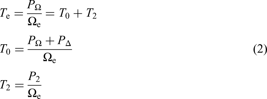
In the formula: m0 is the number of phases, E2 is the rotor induced electromotive force, I2 is the rotor induced current, and I2cosψ is the effective component of the rotor current. By dividing the output power equation of the rotor by the mechanical angular velocity Ωe, the torque equation of the rotor can be obtained:
Planetary gear wear model
Tooth wear represents the primary manifestation of tooth failure. The increase in tooth surface wear has a direct impact on the backlash of the gear, hence influencing the nonlinear dynamic characteristics of the gear. One of the most often employed wear calculation models is Archard wear. Figure 5 depicts a simplified representation of the Archard wear model.
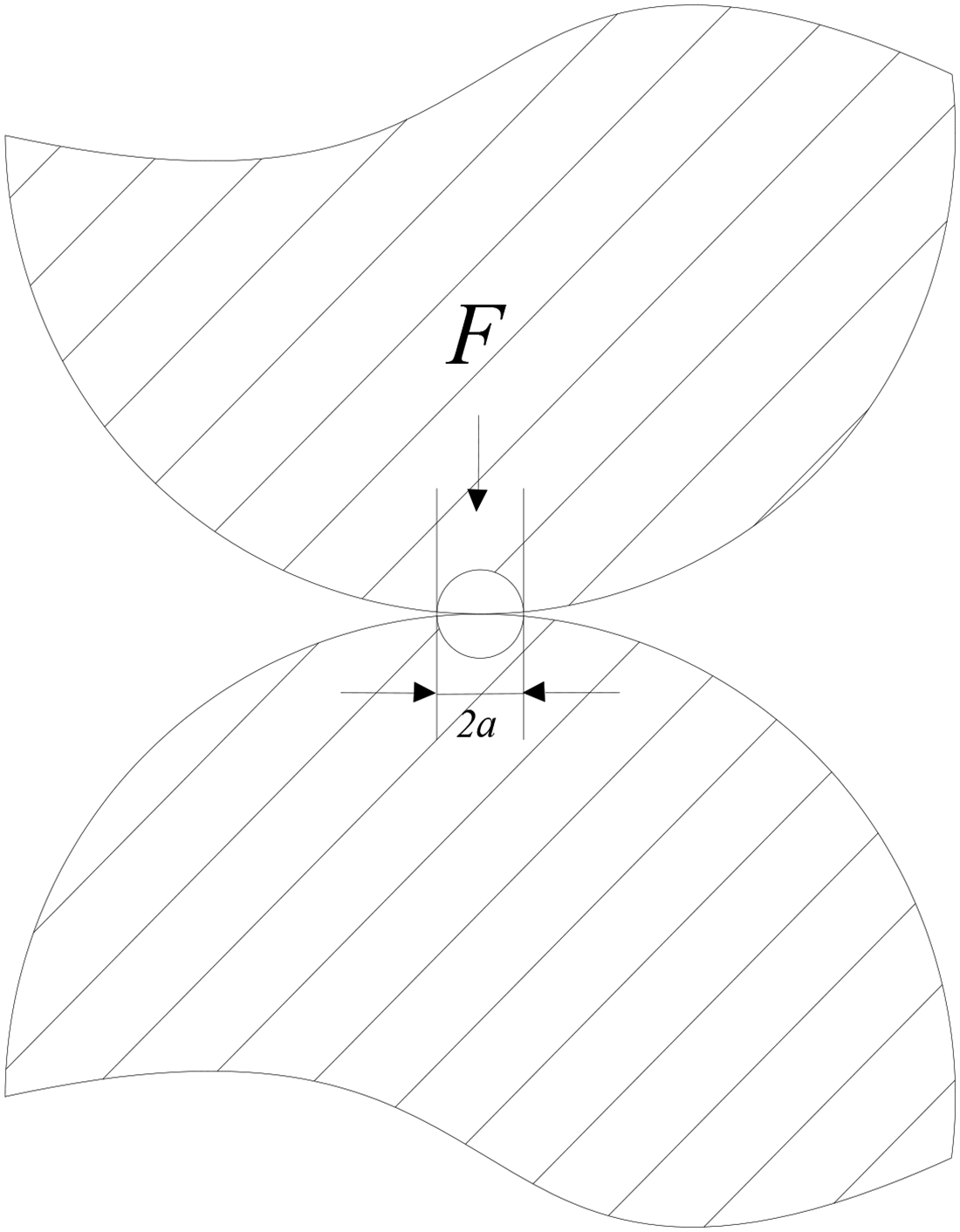
Archard wear model.
The following is a planetary gear wear model based on the Archard wear model, with the formula
28
:

Calculation of frictional force and torque considering lubrication
During the process of gear meshing, each pair of gears undergoes a process of meshing in and out, so the direction of frictional force is always changing. The frictional force on the tooth surface of gear pair i is:

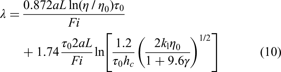
Figure 6 shows the instantaneous curvature radius of meshing tooth pairs. The friction coefficient of lubricating oil is
29
:
Curvature radius of meshing tooth pairs.
Where:
Gear mesh stiffness considering wear
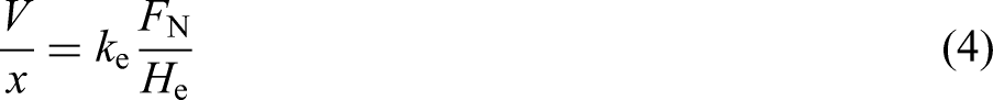
Assuming the area of the xth segment is Sx and the cross-sectional modulus is Ix, uniform wear on the tooth surface will change Sx and Ix. Assuming the wear depth of the xth segment is hx. Once the gear becomes worn, it will induce compression deformation, bending deformation, and shear deformation at the point of meshing. Figure 7 illustrates various parameters relevant to the analysis of the gear system. The thickness of the x segment is denoted as dx, while FN represents the positive pressure exerted on the gear surface. Poisson's ratio is denoted as ν, and E represents the elastic modulus of the material. Furthermore, αx denotes the angle formed between the straight line where the load is situated and the centerline of the gear teeth. The distance from the x segment to the load point along the b-axis direction is denoted as Lx1, which can be utilized to determine the bending and shear forces at the contact point. The deformation resulting from the application of compressive forces is
30
:
Gear stiffness model.
In the context of real applications, it is imperative to take into account the supplementary deformation resulting from the elasticity of the gear teeth.

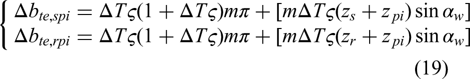
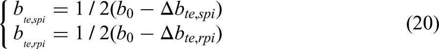
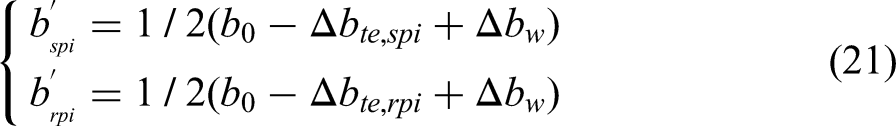
Tooth side clearance considering temperature and wear
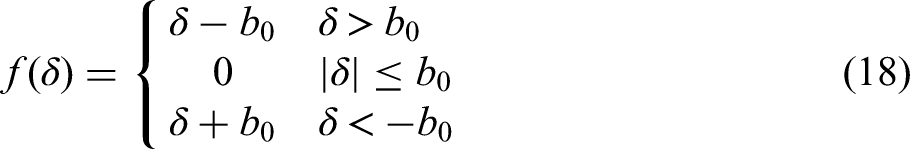
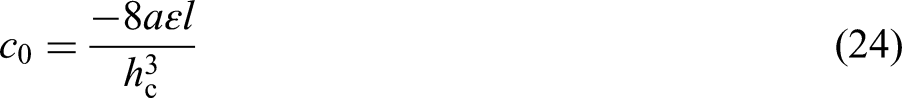
Backlash, arising from gear manufacturing, installation problems, and wear, has a significant impact on the periodic variations in gear contact and subsequently influences the nonlinear features of planetary gear systems in real-world operational settings. The nonlinearity of the backlash of gears is evident, as it prevents the meshing force and displacement of the meshing pair from being accurately described by a linear function. The initial backlash of gears can be denoted as variable 2b0. Hence, it is possible to express it using a piecewise function:
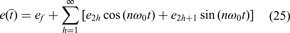
Consider the equivalent meshing damping and transmission error of lubrication
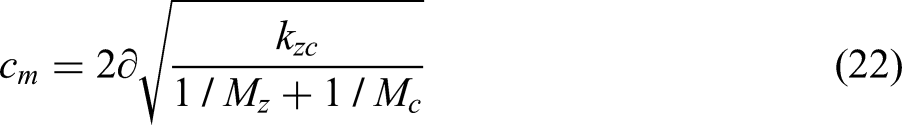
The determination of meshing damping can be achieved through the utilization of empirical formulae:


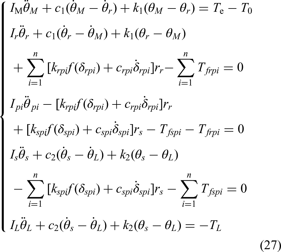
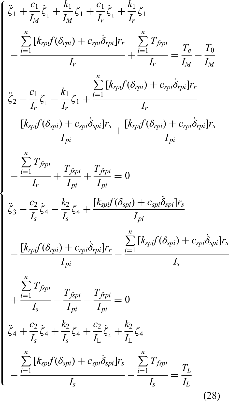
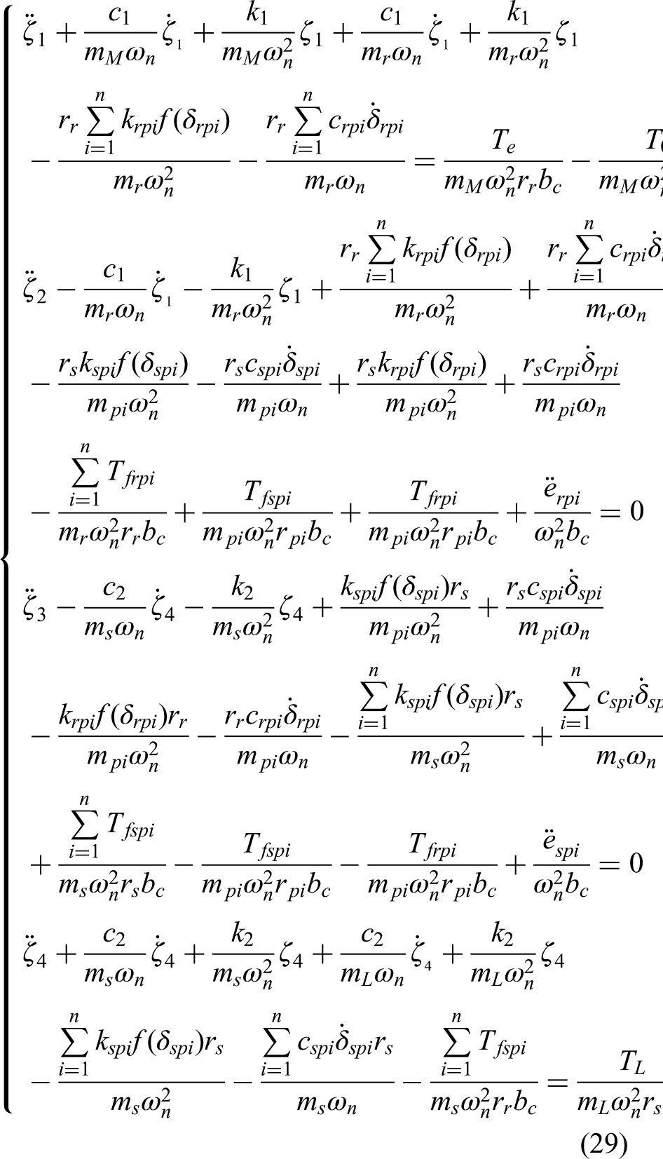
Dynamic equations considering the coupling effect of multiple fields of electricity, heat, and force
Based on the model in Figure 2 and using the Newton Euler method, the dynamic equation is established as follows:
Nonlinear dynamic characteristics analysis of electric thermal mechanical multi field coupled motor gear system
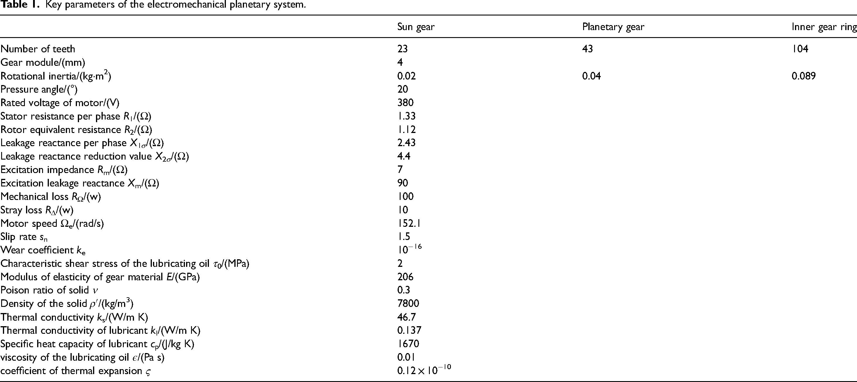
This paper examines the impact of electrical signal, wear, and meshing damping ratio on the nonlinear properties of the three-phase asynchronous motor gear system. The study employs MATLAB software to compute the dynamic differential equation. The relevant parameters of electromechanical planetary gears are shown in Table 1
Key parameters of the electromechanical planetary system.
The influence of current and voltage variations on the nonlinear characteristics of systems
The measurement of current and voltage signals can be accomplished through the utilization of an ammeter and voltmeter. Consequently, the condition of the system can be initially ascertained by observing the alterations in current and voltage. The system experiences a temperature increase of 50 degrees Celsius. It is postulated that the wear of the gear is 10 microns. The coefficient of time-varying meshing stiffness is 0.3, while the damping ratio of the meshing process is 0.01. The amplitude of the meshing error is 0.2. Additionally, the motor voltage is rated at 380 V. The system's nonlinear dynamic response is observed within the current range of 0A to 50A.
Figure 8 shows the bifurcation process of the system when the current signal changes. It can be seen that the electromechanical planetary gear system first experiences a brief chaotic state. At this time, the input current of the motor is very small, which may cause instability in the system. Figure 9 shows the phase diagram, spectrum diagram, time-domain diagram, and Poincare cross-sectional diagram of the system in the chaotic state when the current is 4A; As the current increases, the system enters a single periodic motion state. Figure 10 shows the phase diagram, spectrum diagram, time domain diagram, and Poincare cross-section diagram of the system in chaotic state when the current is 10A. At this time, the phase diagram is a smooth circular ring, the cross-section diagram shows a point set, the spectrum diagram shows a peak, and the time domain diagram shows a clear periodic curve; As the current further increases, the system enters an unstable chaotic motion state again. Figure 11 shows the phase diagram, spectrum diagram, time domain diagram, and Poincare cross-section diagram of the system when the current is 25A. At this time, the phase diagram contains chaotic factors and shows multiple irregular lines in circles. The corresponding cross-section diagram shows a series of discrete point sets, and the spectrum diagram shows multiple different peaks. The time domain diagram does not have obvious periodic patterns.
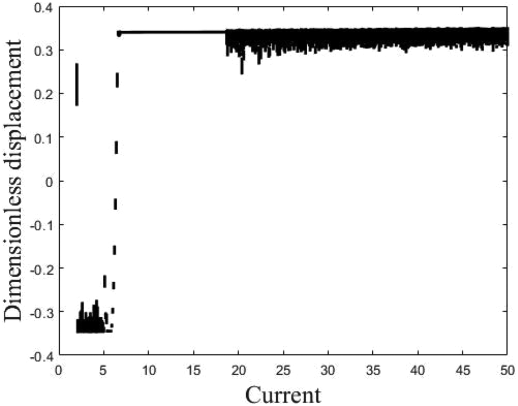
Bifurcation diagram of the system with changes in current signals: (a) phase diagram; (b) time domain diagram; (c) spectrogram; (d) Poincare cross section.
Single cycle state of the system when the current is 4 A: (a) phase diagram; (b) time domain diagram; (c) spectrogram; (d) Poincare cross section.
Chaotic state of the system at a current of 10 A.
Chaotic state of the system at a current of 25 A: (a) phase diagram; (b) time domain diagram; (c) spectrogram; (d) Poincare cross section.
Analyze the nonlinear dynamic response of a system with voltage in the range of 200 V to 500 V, while keeping other parameters constant.
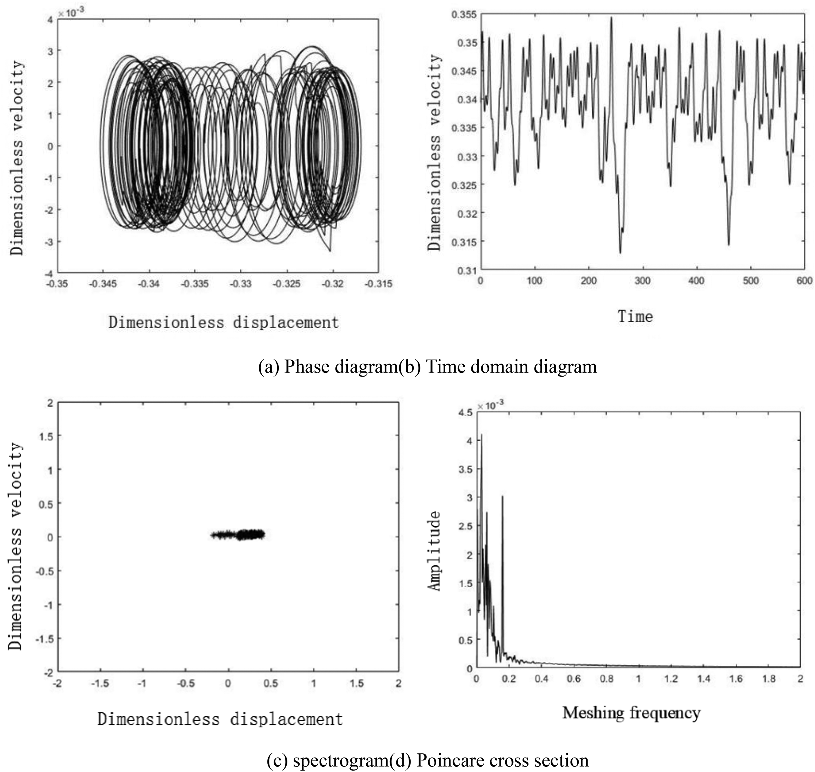
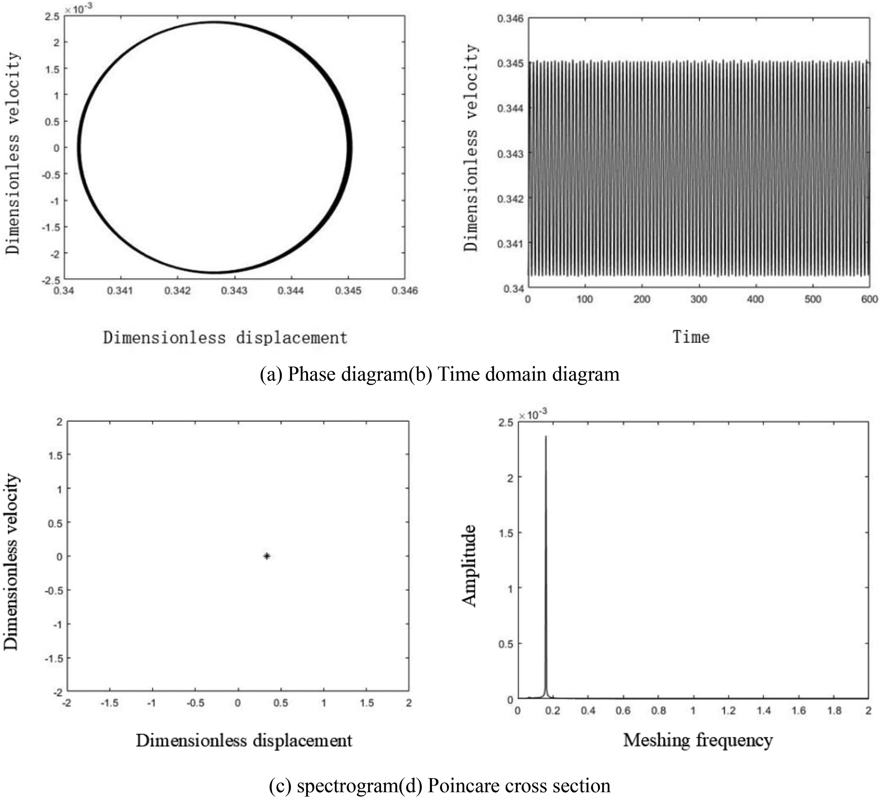
Figure 12 shows the bifurcation process of the system when the voltage signal changes. Firstly, the motor experiences a single cycle state at a voltage of 220 V to 360 V, during which the system operates stably. Figure 13 shows the phase diagram, spectrum diagram, time-domain diagram, and Poincare cross-sectional diagram of the system under a single cycle state at a voltage of 300 V, However, when the voltage exceeds the rated motor voltage of 380 V, the system enters an unstable chaotic motion state, and the system is unstable. It is not recommended to continue working, Figure 14 shows the phase diagram, spectrum diagram, time domain diagram, and Poincare cross-sectional diagram of the system in chaotic state at a voltage of 400 V. At this time, the phase diagram contains chaotic factors and presents multiple irregular lines in circles, corresponding to a series of discrete point sets. The spectrum diagram shows multiple different peaks, and the time domain diagram does not show obvious periodicity.
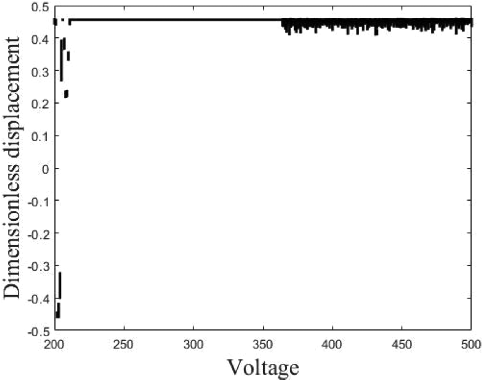
Bifurcation diagram of system with voltage signal variation: (a) phase diagram; (b) time domain diagram; (c) spectrogram; (d) Poincare cross section.
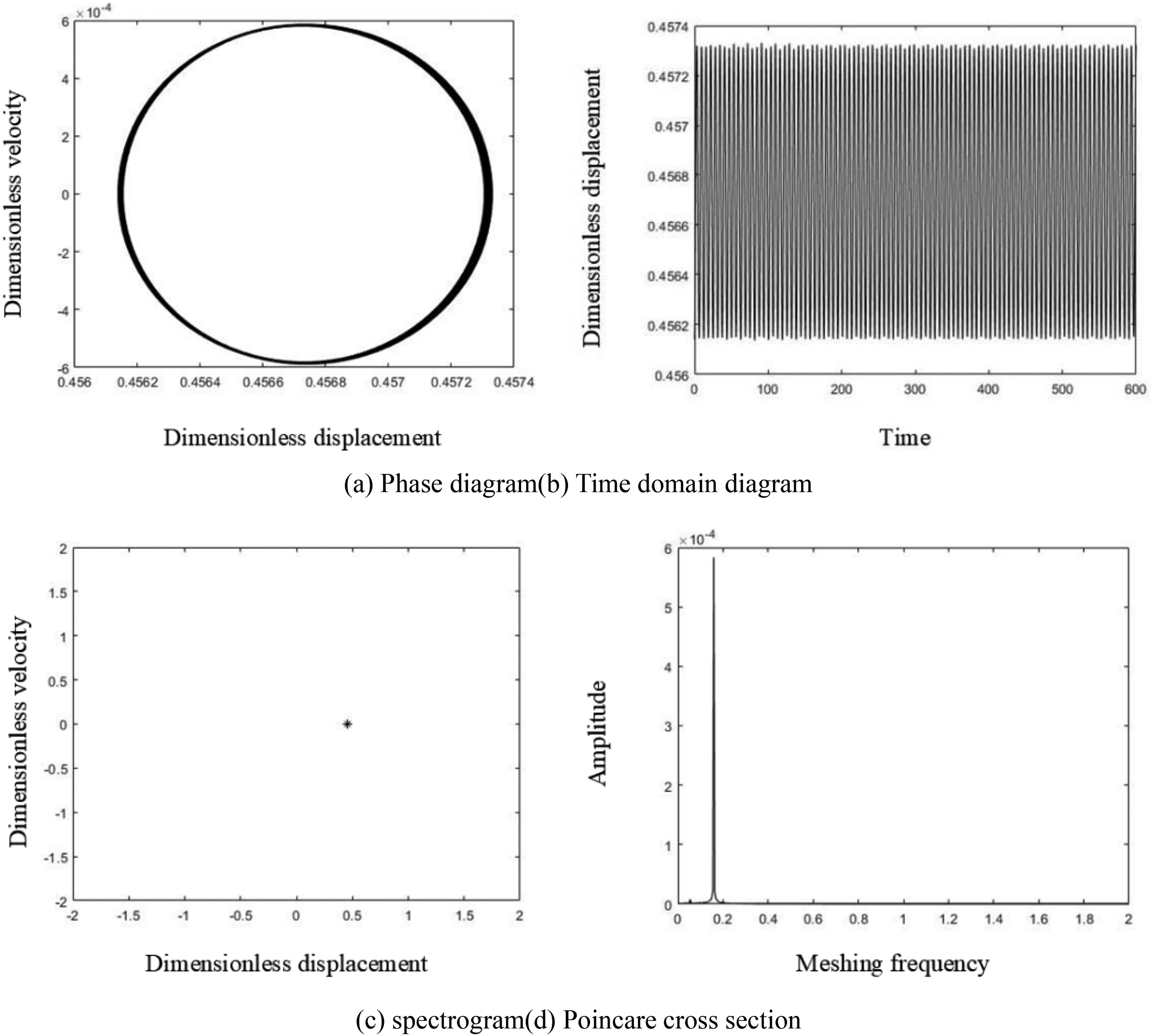
Single cycle state of the system at a voltage of 300 V: (a) phase diagram; (b) time domain diagram; (c) spectrogram; (d) Poincare cross section.
Chaotic state of the system at a voltage of 400 V.
In summary, the movement status of the system can be roughly observed through changes in voltage and current signals. Therefore, installing a voltmeter and ammeter in the circuit can monitor the system. When the current signal is between 7A and 18A, the system is in a stable state. When the voltage signal exceeds the rated voltage of the motor, the system will gradually become unstable.
The influence of temperature changes on the nonlinear characteristics of the system
The thermal expansion of the gear is influenced by an elevation in temperature, resulting in the deformation of the gear and subsequent alteration of the backlash. The backlash, being one of the internal excitations, has an impact on the nonlinear dynamic response of the gear system. Given an assumed gear wear of 10 microns, a time-varying meshing stiffness coefficient of 0.3, a meshing damping ratio of 0.01, a meshing error amplitude of 0.2, and a motor voltage of 380 V. The investigation focuses on the nonlinear dynamic response of the system within a temperature range spanning from 0 °C to 100 °C.
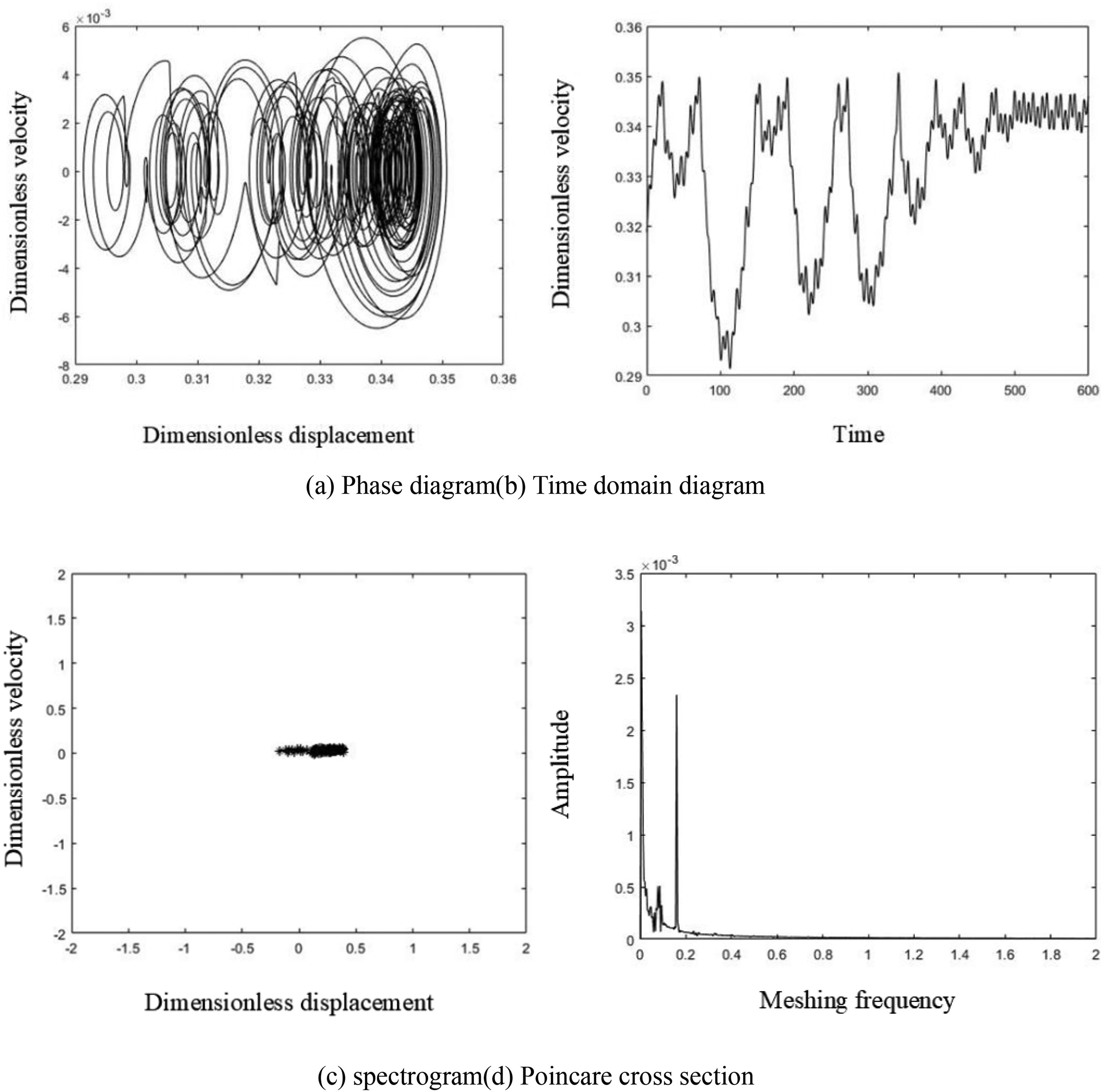
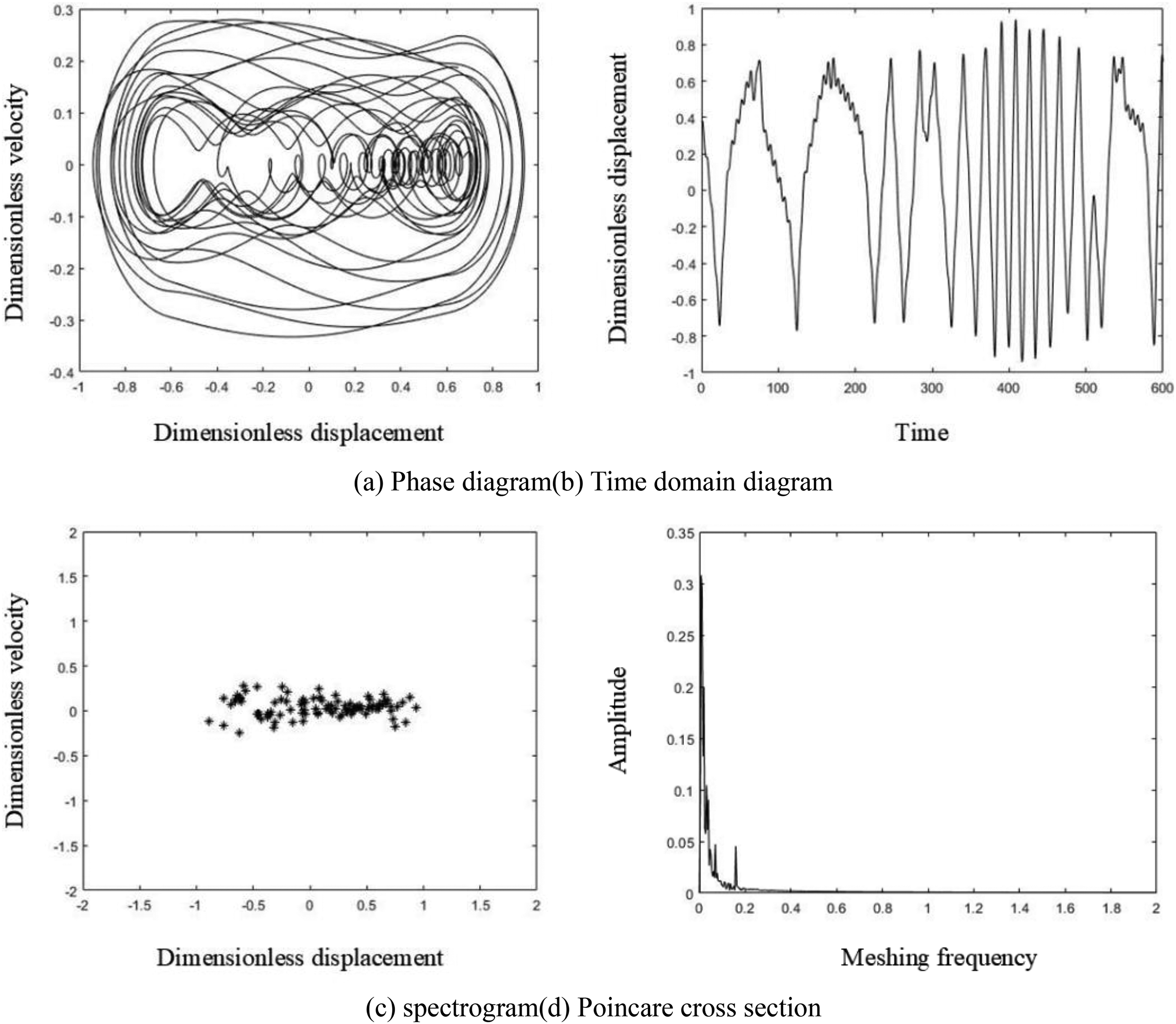
Figure 15 shows the bifurcation process of the system during temperature rise changes. Firstly, the system remains in a chaotic state from a temperature rise of 10 °C to 15 °C. At this time, the system is relatively unstable and it is not recommended to work in this environment for a long time, Figure 16 shows the phase diagram, spectrum diagram, time-domain diagram, and Poincare cross-sectional diagram of the system in a chaotic state with a temperature rise of 10 °C. At this time, the phase diagram contains chaotic factors and presents multiple irregular lines in circles, corresponding to a series of discrete point sets. The spectrum diagram shows multiple different peaks, and the time-domain diagram does not show obvious periodicity; As the temperature rise further increases, Figure 17 shows the phase diagram, spectrum diagram, time domain diagram, and Poincare cross-section diagram of the system in a three-period motion state at a temperature rise of 30 °C. At this time, the phase diagram shows three circles, the cross-section diagram shows three-point sets, the spectrum diagram shows three peaks, and the time domain diagram shows three obvious periodic curves; When the temperature rises from 42 °C to 56 °C, the system undergoes a two-period motion. Figure 18 shows the phase diagram, spectrum diagram, time domain diagram, and Poincare cross-section diagram of the system with a temperature rise of 50 °C. The phase diagram shows two circles, the cross-section diagram shows two-point sets, the spectrum diagram shows two peaks, and the time domain diagram shows two obvious periodic curves; When the temperature rises from 56 °C to 80 °C, the system is in an unstable chaotic motion state. Figure 19 shows the phase diagram, spectrum diagram, time domain diagram, and Poincare cross-section diagram of the system with a temperature rise of 65 °C; When the temperature rises from 80 °C to 100 °C, the system returns to a stable three cycle motion state. Figure 20 shows the phase diagram, spectrum diagram, time domain diagram, and Poincare cross-section diagram of the system with a temperature rise of 90 °C.
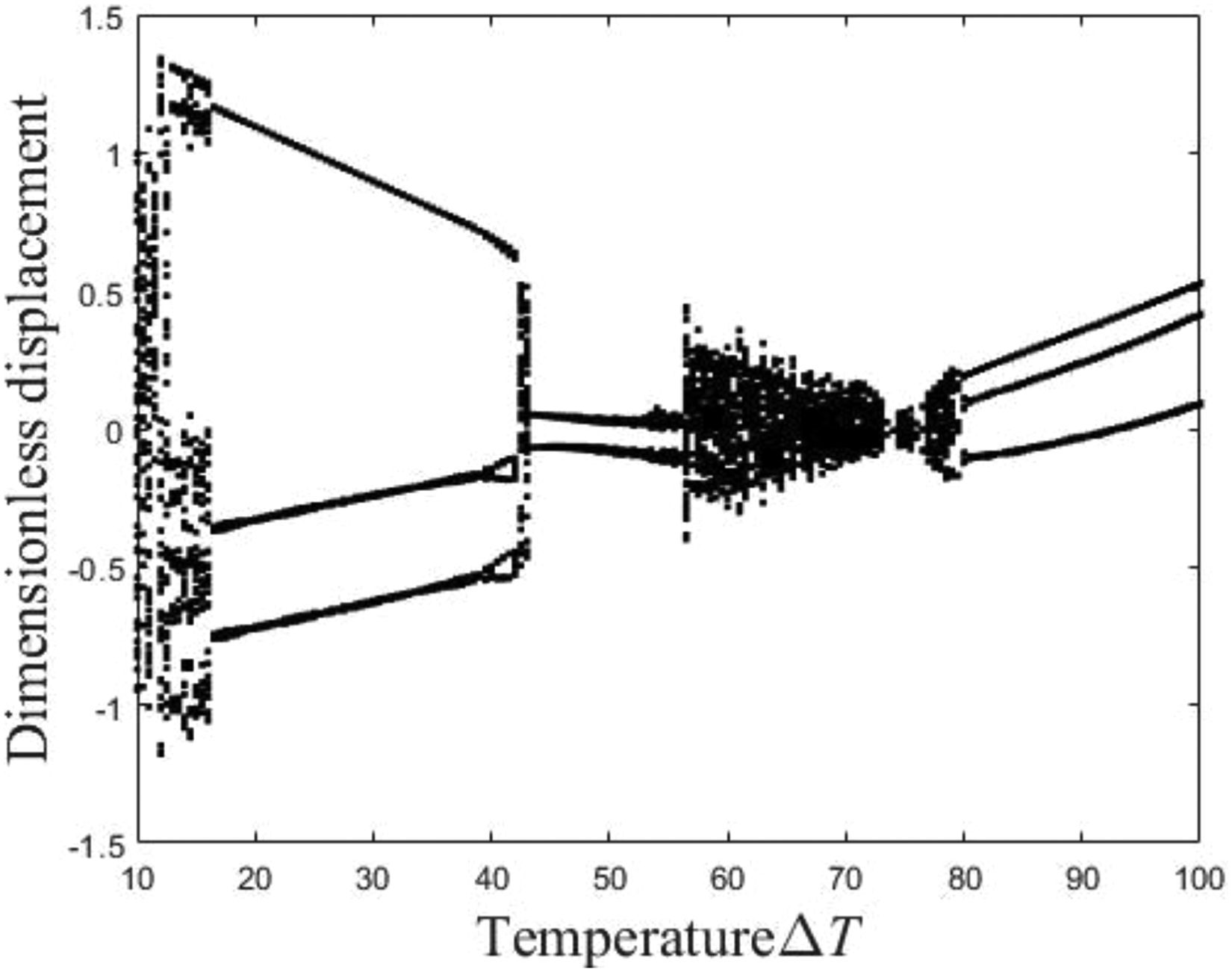
Bifurcation diagram of the system with temperature: (a) phase diagram; (b) time domain diagram; (c) spectrogram; (d) Poincare cross section.
Chaotic state of the system at a temperature rise of 10 °C: (a) phase diagram; (b) time domain diagram; (c) spectrogram; (d) Poincare cross section.
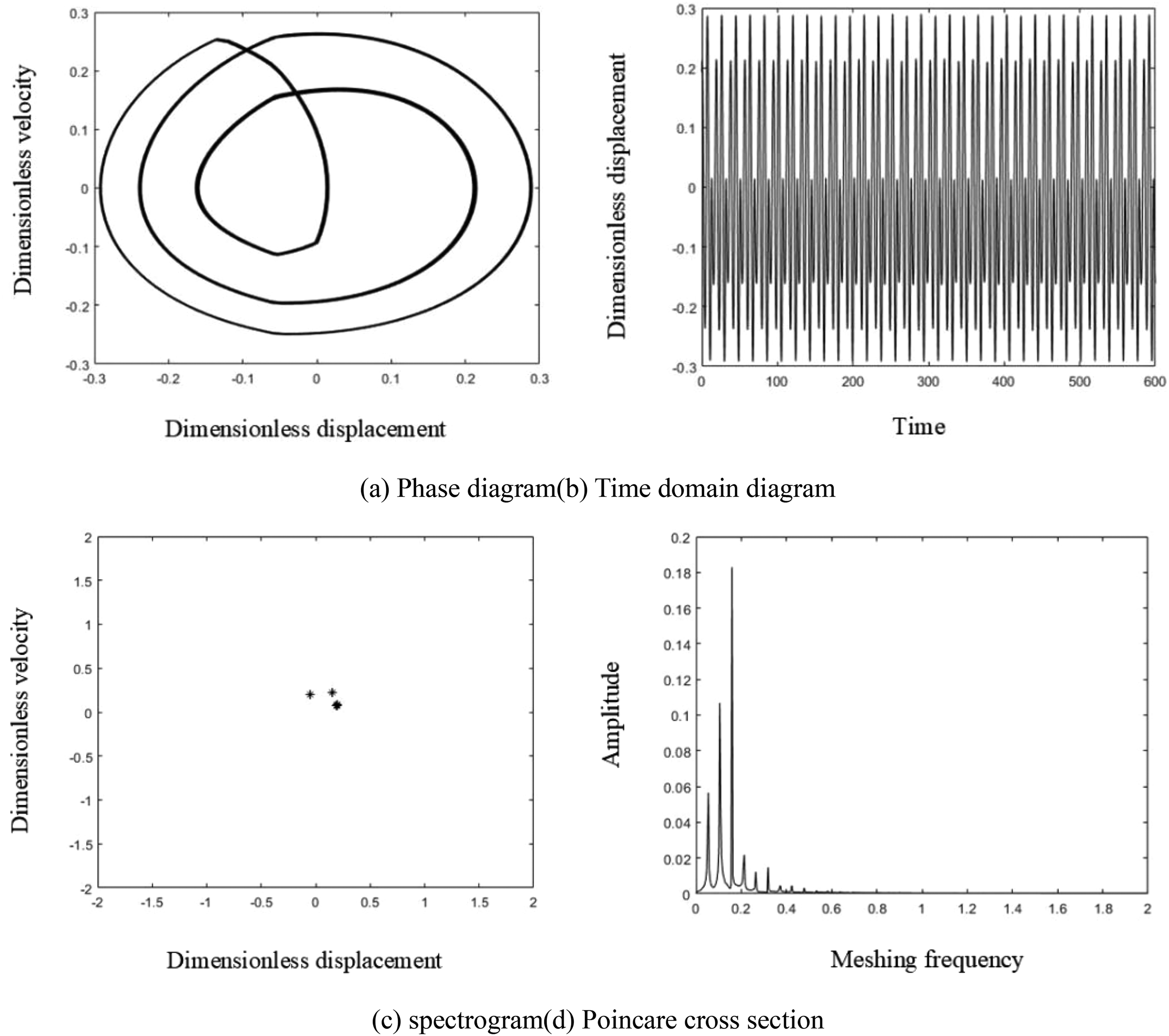
Three cycle state of the system when the temperature rise is 30 °C: (a) phase diagram; (b) time domain diagram; (c) spectrogram; (d) Poincare cross section.
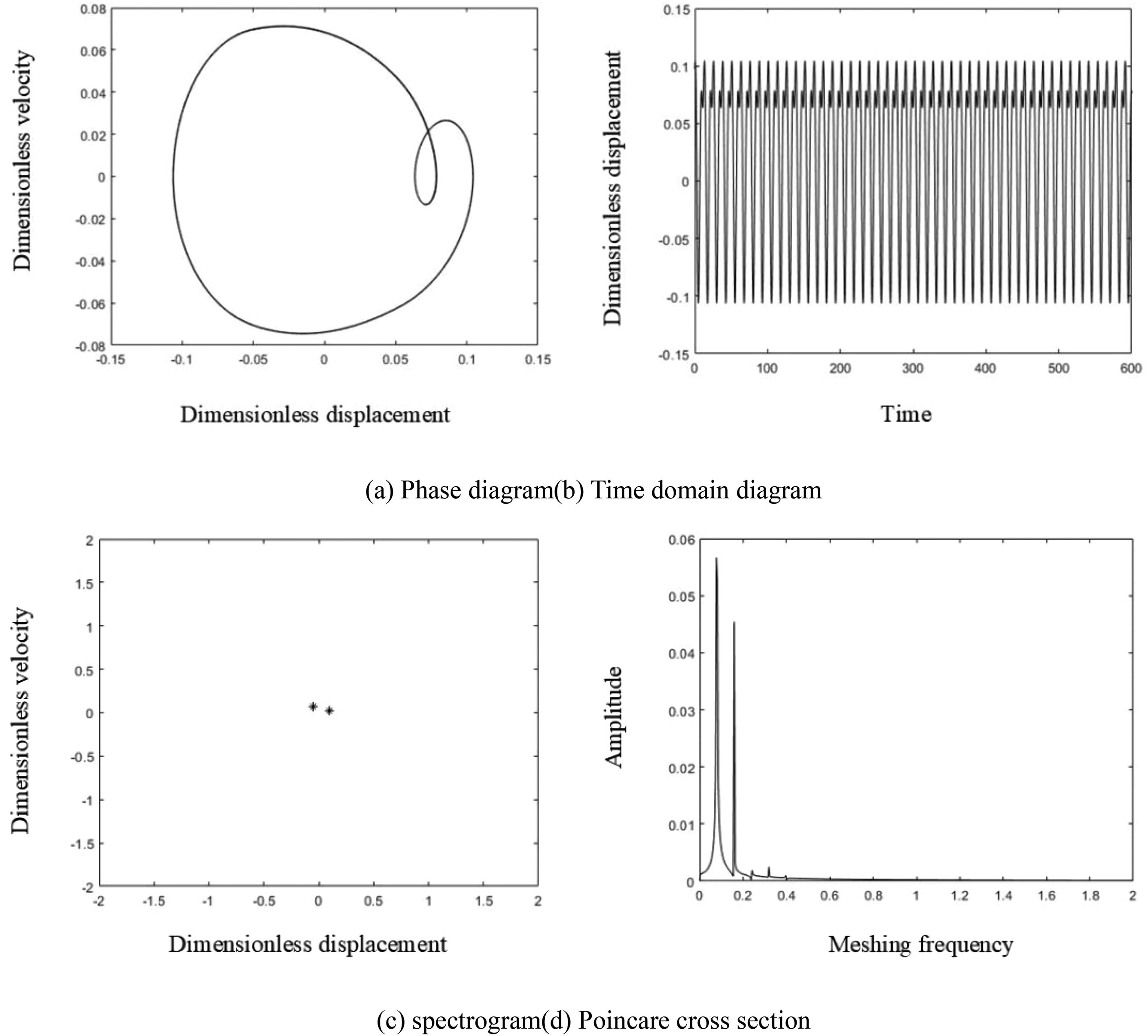
Two cycle state of the system at a temperature rise of 50 °C: (a) phase diagram; (b) time domain diagram; (c) spectrogram; (d) Poincare cross section.
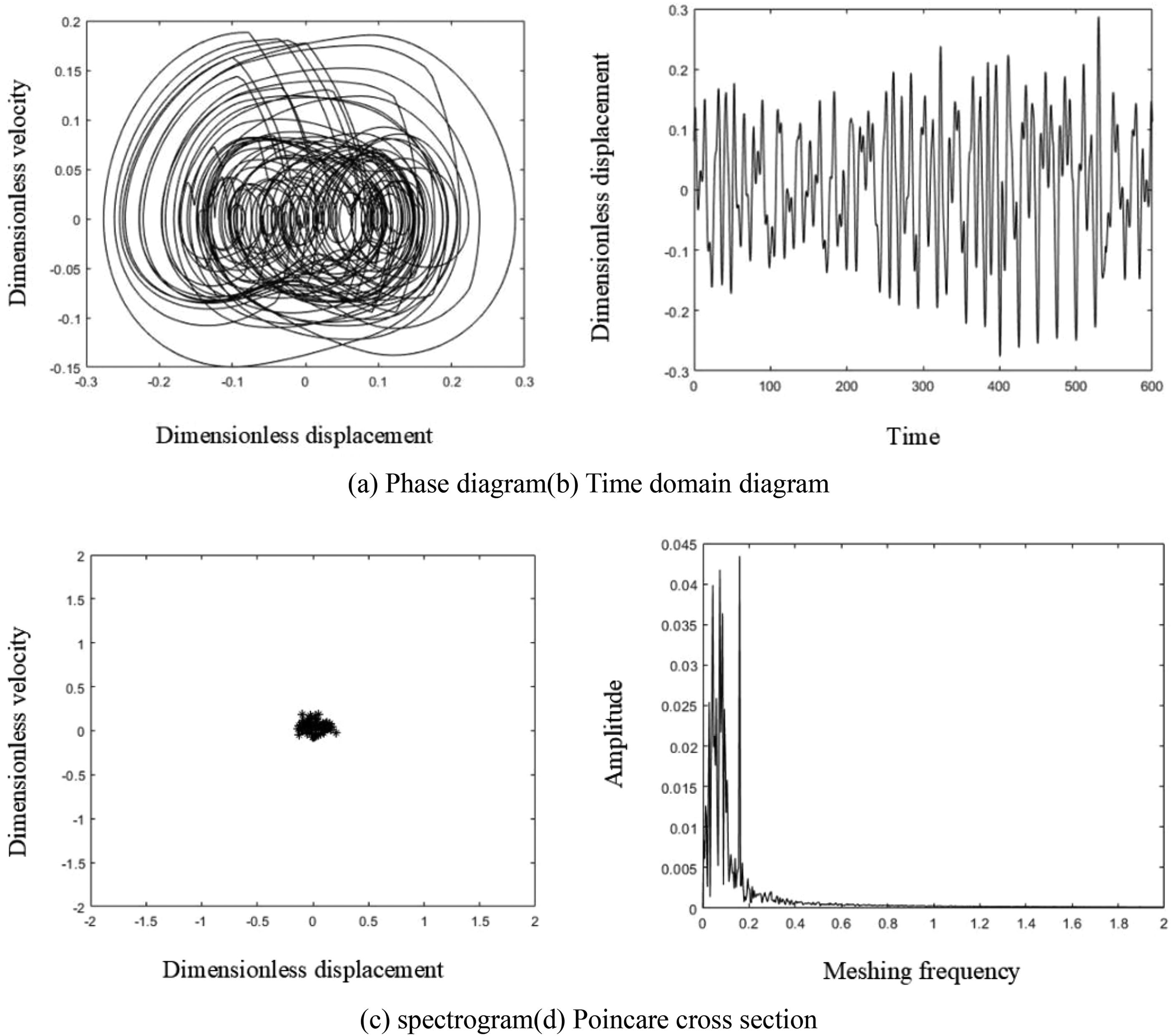
Chaotic state of the system when the temperature rise is 65 °C: (a) phase diagram; (b) Time domain diagram; (c) spectrogram; (d) Poincare cross section.
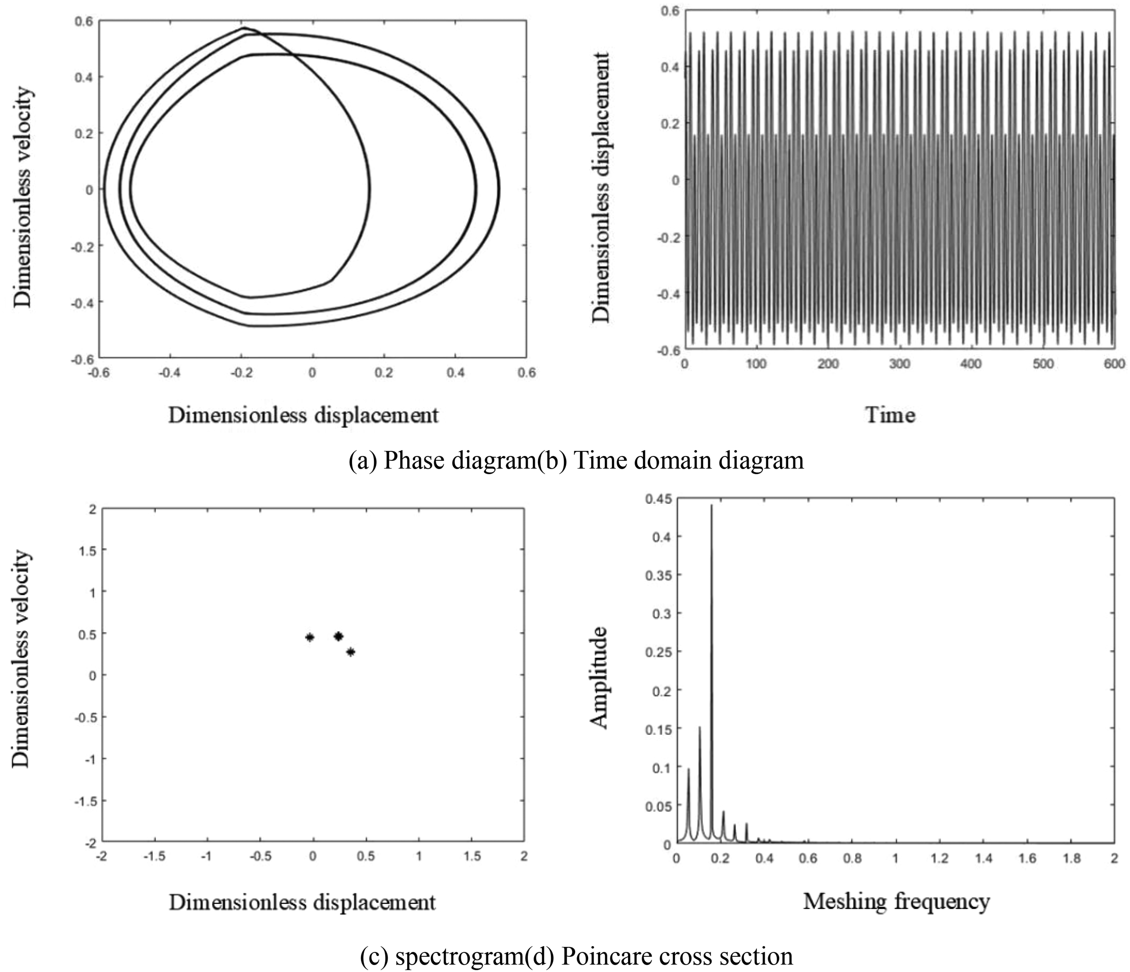
Three cycle state of the system when the temperature rise is 90 °C.
Based on the three-phase asynchronous motor planetary gear system studied in this article, the system needs to operate within the temperature range of 20 °C to 50 °C and 80 °C to 100 °C. It is best not to operate within the temperature range of 56 °C to 80 °C. Overall, a higher system temperature will reduce gear clearance, thereby reducing gear collisions and making the system more stable.
The influence of wear variation on the nonlinear characteristics of the system
The operational conditions of gears exhibit a high degree of intricacy, wherein the intermeshing gears experience frictional contact. In numerous scenarios characterized by inadequate lubricating oil supply, the gear teeth will experience significant wear, hence exerting a substantial influence on the functioning of gears. Hence, it is imperative to do an analysis of the influence of gear wear on the nonlinear dynamics of gears. The time-varying meshing stiffness coefficient is set to 0.3, the meshing damping ratio is set to 0.01, and the meshing error amplitude is set to 0.2. The motor's voltage is specified as 380 V, the distance between the teeth is measured to be 10 microns, and the temperature of the system increases by 50 °C. The investigation focuses on the nonlinear dynamic behavior of the system, specifically considering the range of tooth surface wear spanning from 0 microns to 100 microns.
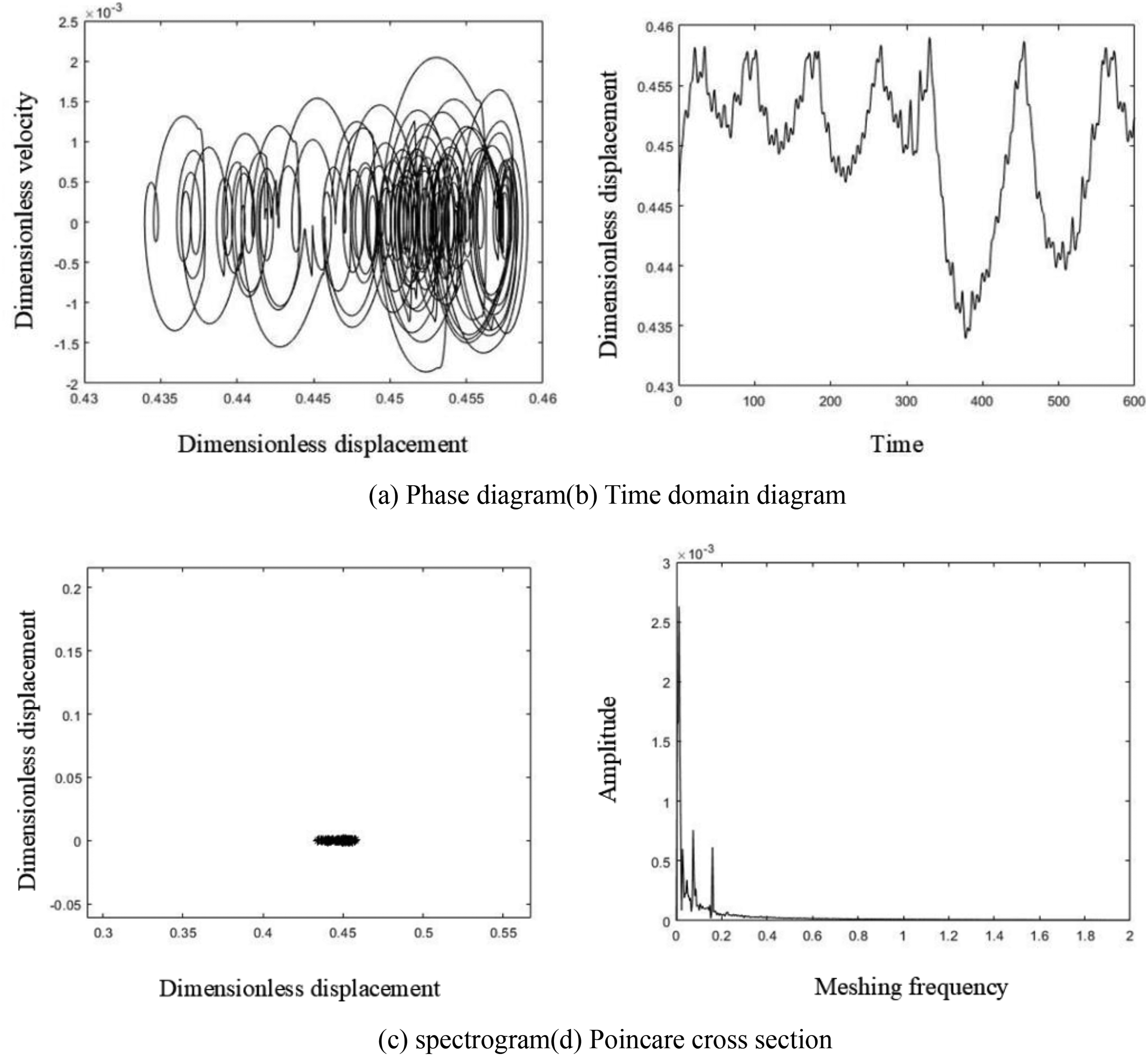
Figure 21 shows the bifurcation process of the system when the wear level changes. Firstly, when the gear wear level is between 3 and 8 micrometers, the system is in a brief chaotic motion state. At this time, the gear is in the running in stage. As the wear level increases, when the wear level is between 8 micrometers and 28 micrometers, the system is in a three-cycle motion state. At this time, the system is in a stable working state, and the wear is within an acceptable range, which will not affect the nonlinear characteristics of the system, Figure 22 shows the phase diagram, spectrum diagram, time-domain diagram, and Poincare cross-sectional diagram of the system in a three-cycle motion state with a wear amount of 20 microns; Subsequently, the wear of the gears further increased. When the wear ranged from 28 microns to 38 microns, the system was in a triple quasi periodic state. At this time, the system was still relatively stable, and although the gears were slightly worn, they could still function normally. Therefore, there was no need to replace the gears. Figure 23 shows the phase diagram, spectrum diagram, time-domain diagram, and Poincare cross-sectional diagram of the system in a chaotic state with a wear of 32 microns; As the gear wear further intensifies, when the gear wear exceeds 38 microns, the system is in a long-term chaotic motion state, and the gear needs to be replaced. Figure 24 shows the phase diagram, spectrum diagram, time-domain diagram, and Poincare cross-sectional diagram of the system in chaotic state when the wear amount is 50 microns.
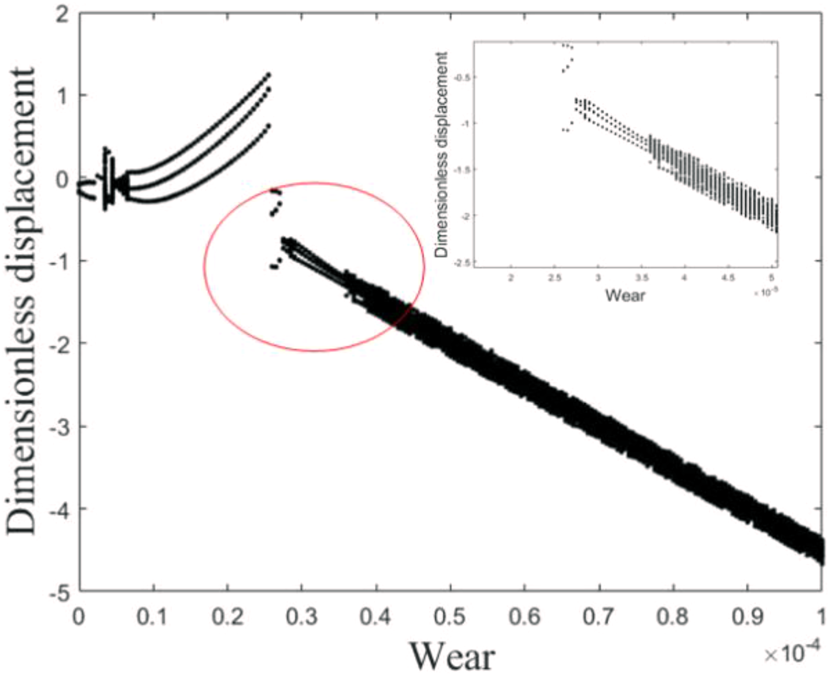
Bifurcation diagram of the system with changes in wear: (a) phase diagram; (b) time domain diagram; (c) spectrogram; (d) Poincare cross section.
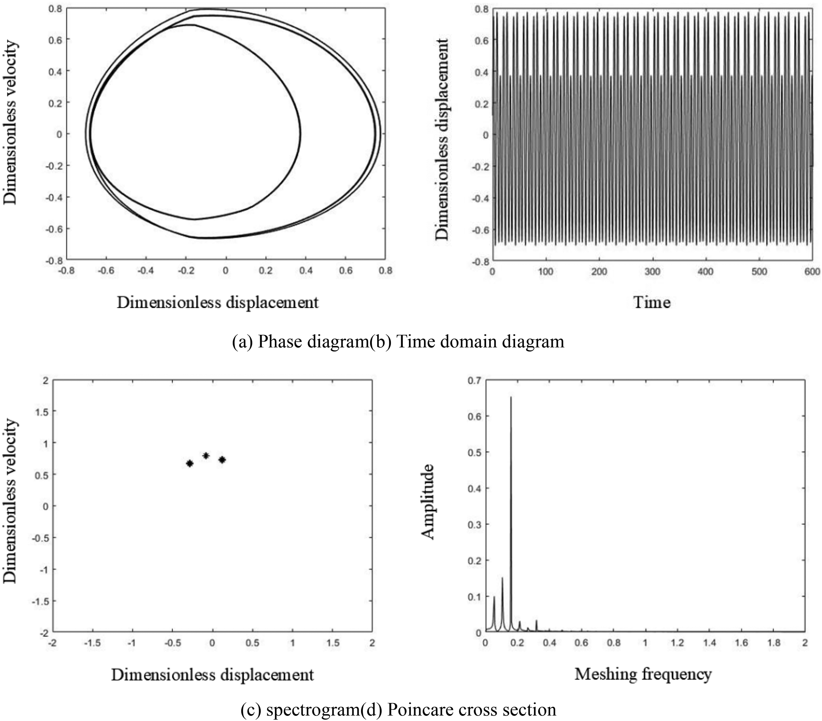
Three cycle state of the system when the wear amount is 20 μm: (a) phase diagram; (b) time domain diagram; (c) spectrogram; (d) Poincare cross section.
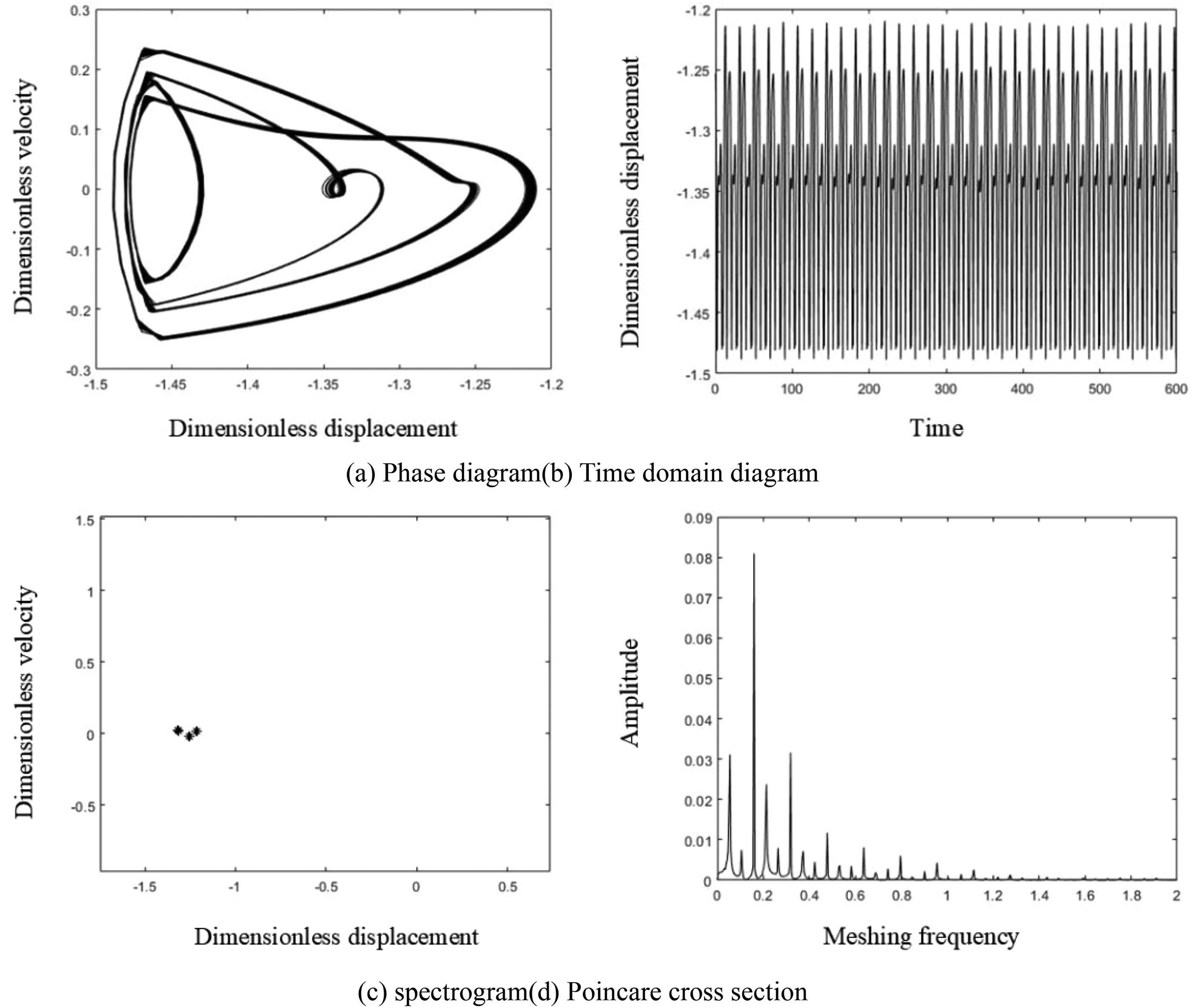
Triple quasi periodic state of the system when the wear amount is 32 microns: (a) phase diagram; (b) time domain diagram; (c) spectrogram; (d) Poincare cross section.
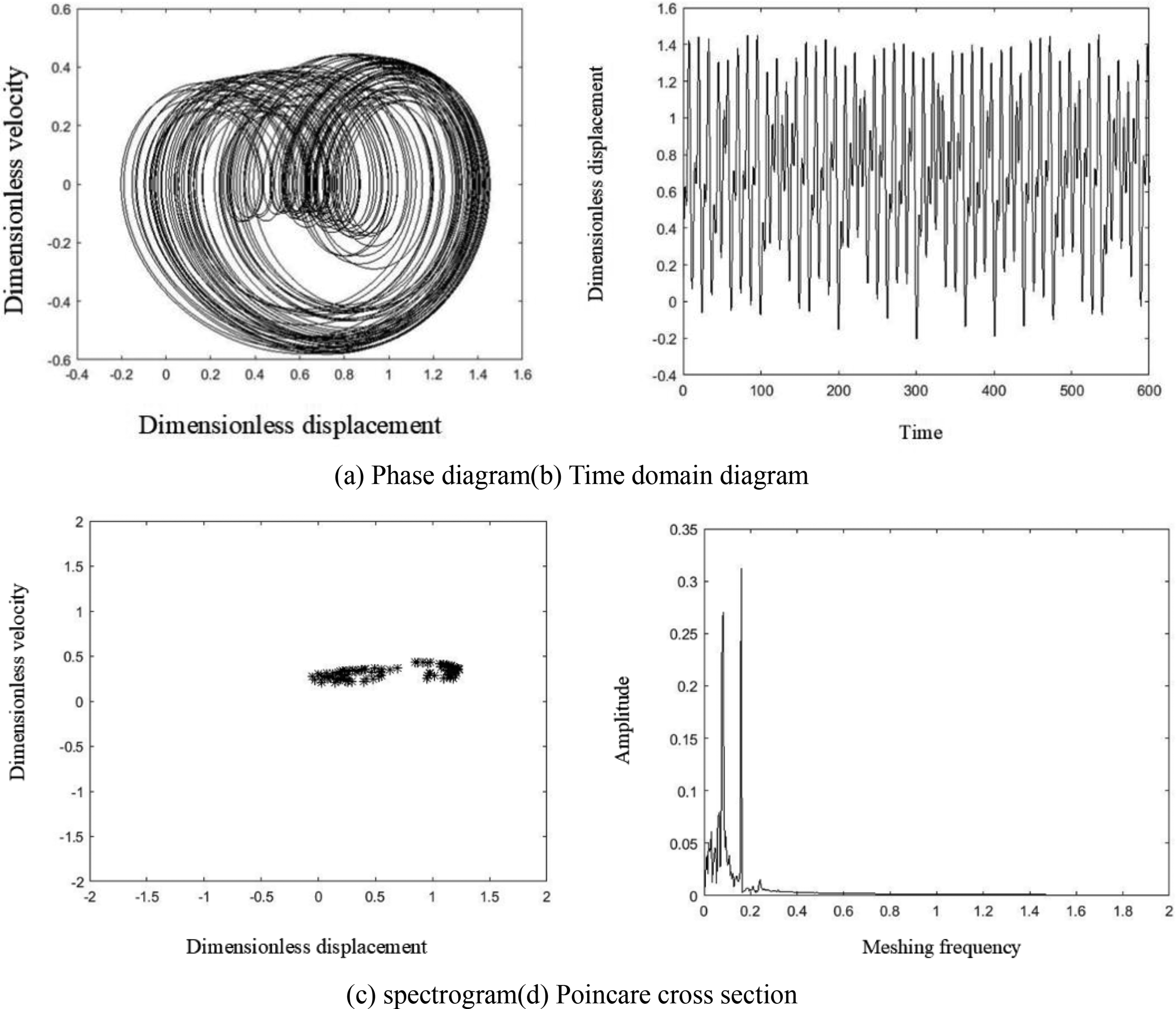
Chaotic state of the system when the wear amount is 50 μm.
Combined with the three-phase asynchronous motor planetary gear system studied in this article, the planetary gears of the system need to be replaced after the wear amount is greater than 38 microns. Excessive wear can cause large backlash between the teeth, increase collisions between the gears, and make the system unstable.
The influence of meshing damping ratio on the nonlinear characteristics of systems
The damping ratio is defined as the ratio between the damping coefficient and the critical damping coefficient. It quantifies the normalized amount of damping in a structural body. The coefficient of time-varying meshing stiffness is assigned a value of 0.3. The wear on the tooth surface is measured to be 15 microns. The amplitude of the meshing error is recorded as 0.2. The motor voltage is specified as the rated voltage of 380 V. The tooth side gap is measured to be 10 microns. Lastly, the system temperature rise is observed to be 50 °C. The meshing damping ratio of the system is considered to have a nonlinear dynamic response, falling within the range of 0.02 to 0.18.
Figure 25 shows the bifurcation process of the system when the meshing damping ratio changes. Firstly, the meshing damping ratio is in the range of 0.02 to 0.135, and the system presents a chaotic state. Figure 26 shows the phase diagram, spectrum diagram, time-domain diagram, and Poincare cross-section diagram of the system in a chaotic state when the meshing damping ratio is 0.04. At this time, the phase diagram contains chaotic factors and presents multiple irregular lines in circles, corresponding to a series of discrete point sets, The spectrogram presents multiple different peaks, while the time-domain graph does not exhibit obvious periodic patterns; As the meshing damping ratio increases, when the meshing damping ratio is in the range of 0.135 to 0.18, the system begins to exhibit a two-period motion state. Figure 27 shows the phase diagram, spectrum diagram, time-domain diagram, and Poincare cross-section diagram of the system in the two-period motion state when the meshing damping ratio is 0.1. At this time, the phase diagram shows two circles, the cross-section diagram shows two-point sets, the spectrum diagram shows two peaks, and the time-domain diagram shows two obvious periodic curves.
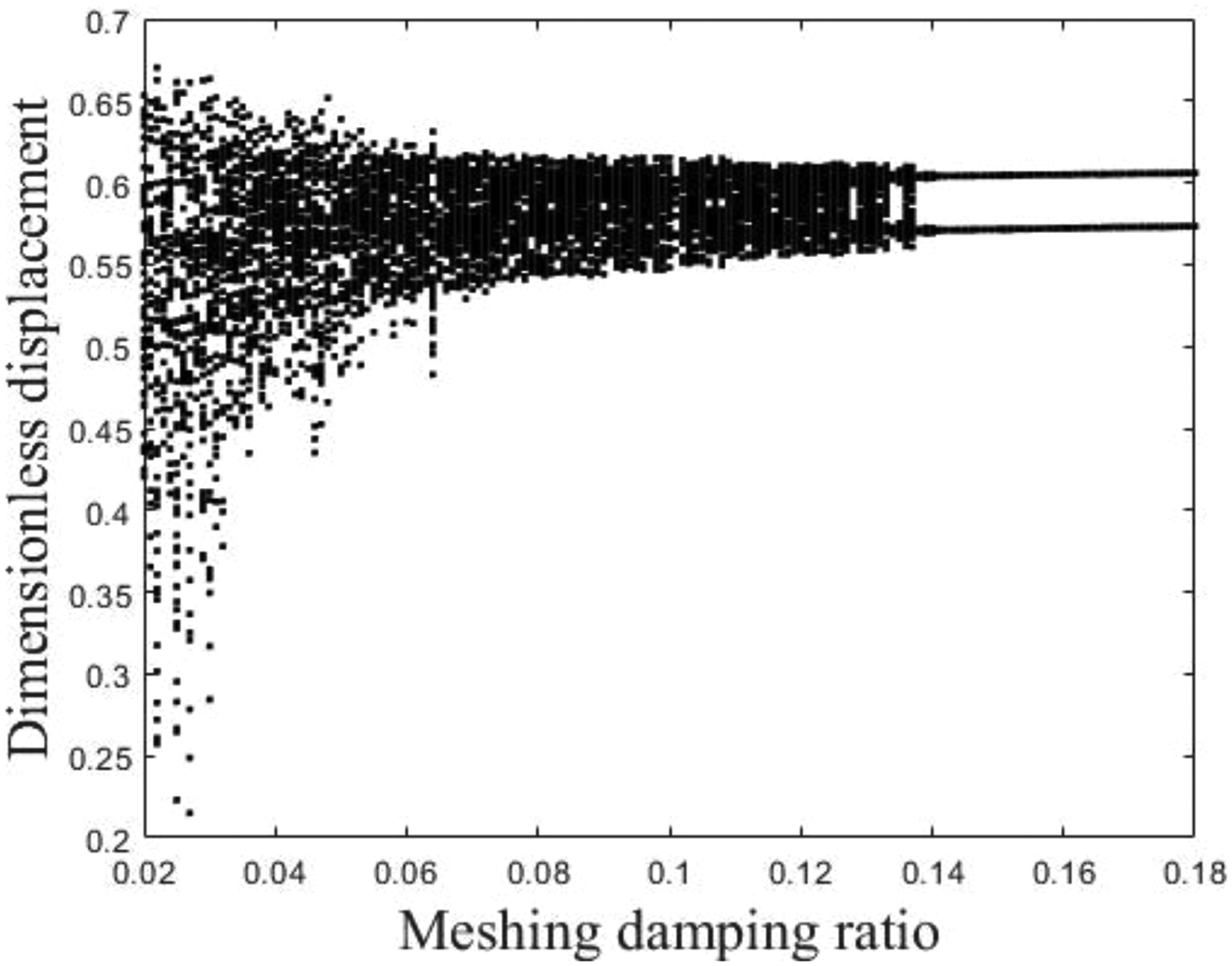
Bifurcation diagram of the system with changes in meshing damping: (a) phase diagram; (b) time domain diagram; (c) spectrogram; (d) Poincare cross section.
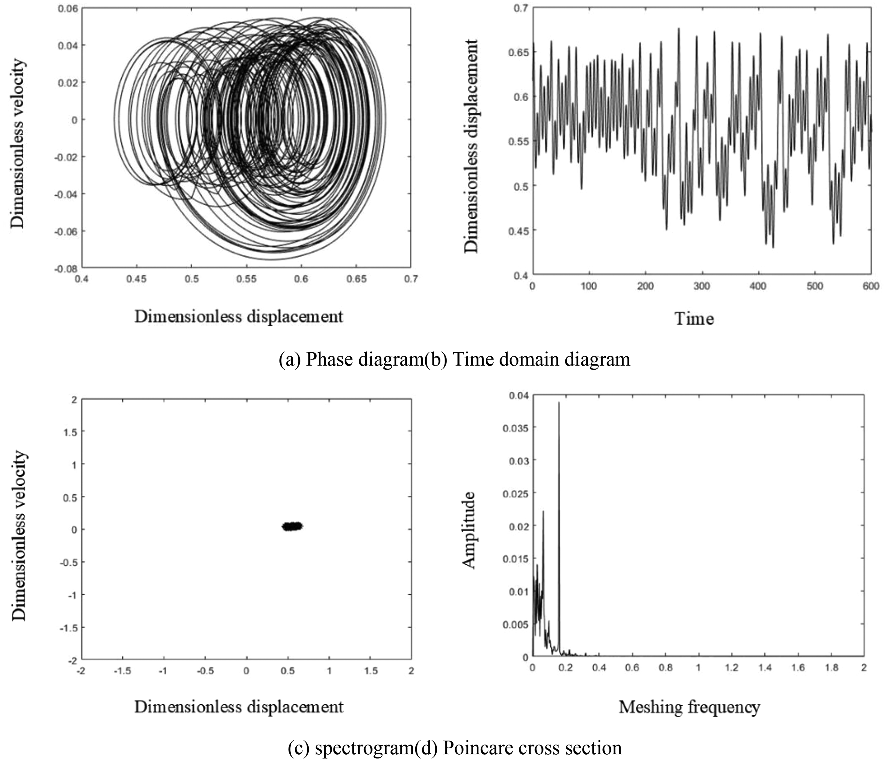
Chaotic state of the system when the meshing damping ratio is 0.04: (a) phase diagram; (b) time domain diagram; (c) spectrogram; (d) Poincare cross section.
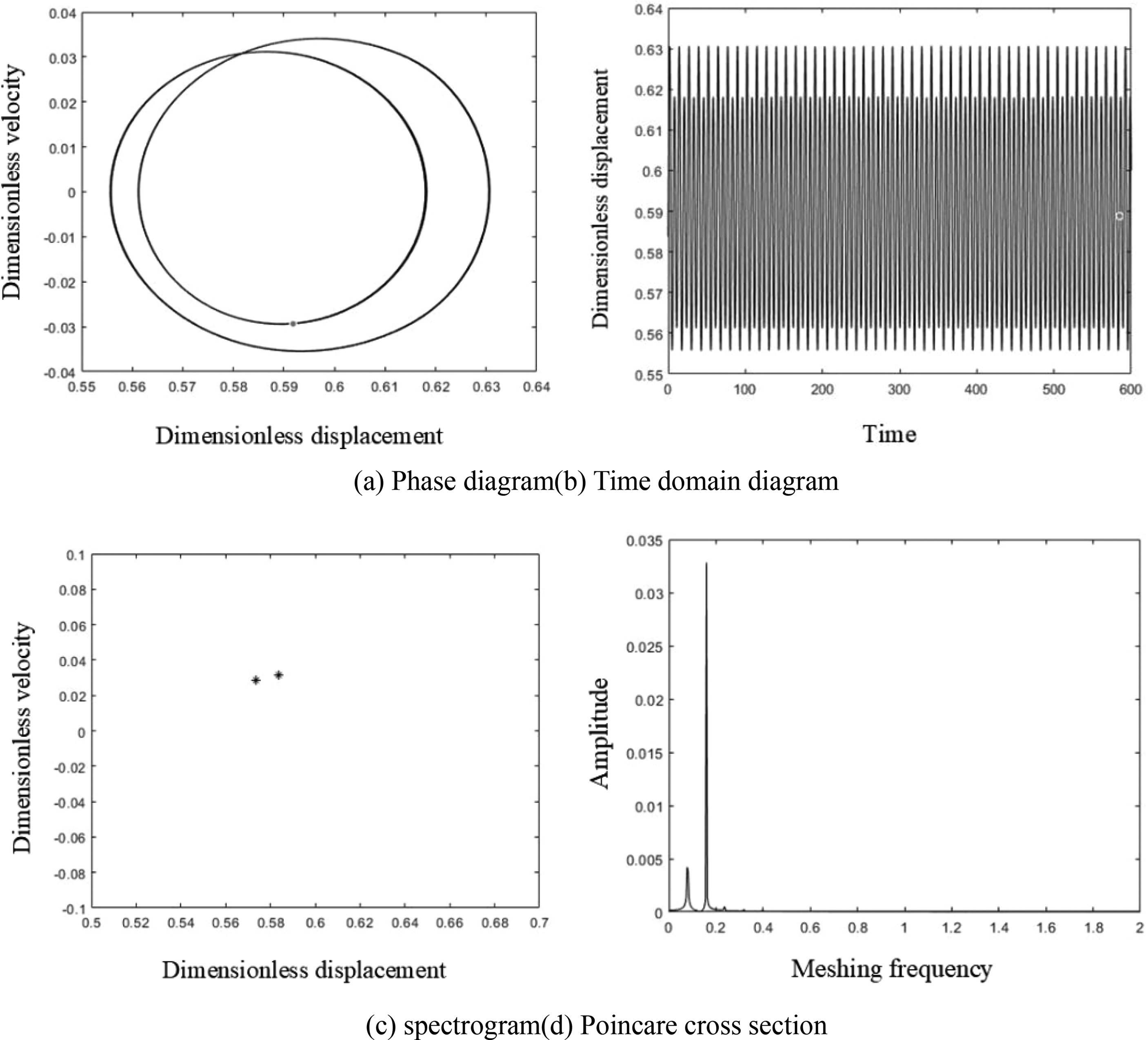
Two cycle state of the system when the meshing damping ratio is 0.1.
Combined with the three-phase asynchronous motor planetary gear system studied in this article, when the system temperature rises to 50 °C, as the meshing damping ratio increases, the system will transition from chaotic motion to periodic motion. Therefore, while ensuring the efficiency of gear transmission, increasing the meshing damping ratio can reduce the vibration amplitude of the system, make the transmission smoother, and extend the gear life.
Conclusion
This article establishes a dynamic model of electromechanical planetary gears under the coupling of electric, thermal, and mechanical fields. Factors such as temperature rise, motor current and voltage, tooth wear, lubrication, gear mesh damping ratio, and tooth surface friction are considered. The bifurcation characteristics of the nonlinear system are analyzed using bifurcation diagrams, time-domain diagrams, phase diagrams, frequency spectra, and Poincaré cross-sections. The following conclusions are drawn:
By judging the bifurcation characteristics of the system through current and voltage signals, the system is in a stable state when the current signal is between 7A and 18A. When the voltage signal exceeds the rated voltage, the system will gradually become unstable. As the temperature rise increases, the system undergoes periodic motion chaotic motion periodic motion. Working within the temperature range of 56 °C to 80 °C will intensify the collision between gears, putting the system in an unstable motion state. The continuous engagement in labor activities might lead to the gradual deterioration of gears. When the wear of the planetary gear surpasses a threshold of 38 microns, the system will transition into an unstable and chaotic motion. This increased wear results in a higher backlash between the teeth of the gears, leading to heightened collisions and further destabilizing the system. As the damping ratio of the meshing increases, the planetary gear system of the three-phase asynchronous motor will undergo a transition from chaotic motion to periodic motion. Hence, by augmenting the meshing damping ratio, the system's chaotic motion may be effectively mitigated, thereby enhancing the transmission's efficiency, promoting smoother operation, and prolonging the lifespan of the gears.
Footnotes
Acknowledgment
This work was supported by the Science and technology research project of Jiangxi Provincial Department of Education (Grant No. GJJ210634) and the Natural Science Foundation of Jiangxi Province (Grant No. 20161BAB206153).
Data availability
The data cannot be accessed on the webpage specified in the paper.
Declaration of conflicting interests
The authors declared no potential conflicts of interest with respect to the research, authorship, and/or publication of this article.
Funding
The authors disclosed receipt of the following financial support for the research, authorship, and/or publication of this article: This work was supported by the Natural Science Foundation of Jiangxi Province, Science and technology research project of Jiangxi Provincial Department of Education (grant numbers 20161BAB206153, GJJ210634).