
Abstract
Rolling element bearing is a key component in the rotating machinery, especially in the rotor-bearing system which often shows a complex nonlinear dynamic characteristic due to the presence of the internal clearance between the rolling elements and the races. A nonlinear model of the rotor-bearing is developed and the nonlinear dynamic analysis is carried out in this article. The dynamic equations are derived based on the Hertzian contact theory, considering whether there existed an internal clearance between a rolling element and the races at a moment and how much the contact force of the rolling element is during the interface. With the help of the bifurcation diagrams, Poincare maps and the orbit of center for the axis, the effect of the rotating speed, the clearance, and the stiffness on the dynamic response are investigated. The bearing system exhibits the complicated dynamic behaviors such as the periodic motion, the quasi-periodic motion, the chaos, and the jump phenomenon; the rolling element system is sensitive to the variation of the rotating speed, the clearance, and the stiffness in some ranges. The results are meaningful to the practical prediction of the vibrational response; the work is significant in theoretical understanding of the nonlinear dynamic mechanism. This research offers an analytical method to check the parameters to prevent the bearings from the dangerous working conditions.
Introduction
Rotating machinery is important equipment in power plants, petrochemical plants, aerospace, and so on. Rolling element bearing is a key component in the rotating machinery. When the bearing is operated at a high speed, the bearing system generates the vibrations and the noises. The principle forces that cause these vibrations are the time-dependent nonlinear contact forces which exist between the rolling elements and races (the inner race and the outer race). The rolling element bearing system is substantially a highly nonlinear system which mainly includes the nonlinear restoring forces between the rolling elements and the races, the clearance during the interfaces, and the defects of the elements. The behavior of the nonlinear system demonstrates the unexpected behavior patterns which are extremely sensitive to the system parameters and the initial conditions. An analysis of the rolling element bearing dynamic behavior is essential to predict the vibrational response and design the parameters of the system.
A number of researchers focused on the development of the model and the analysis of the dynamic characteristics for the rolling bearings in last decades. Datta and Farhang 1 developed a nonlinear model for the structural vibrations in the rolling bearings, and they considered the stiffness of the individual region where the rolling elements contact each other, but in this model distributed defects are not considered. Akturk et al. 2 theoretically studied the effect of the varying preload on the vibration characteristics of a shaft bearing system; they suggested that by taking a correct number of balls and an amount of the preload in a bearing, the untoward effect of the ball passage vibrations can be reduced. Xu and Li 3 presented a model which includes the radial clearance and the contact deformation. A planar slider-crank with two deep groove ball bearings is simulated to get a dynamic load distribution characteristic of the bearings. Harsha et al. 4 developed an analytical model to predict the nonlinear dynamic responses in a rotor-bearing system because of the surface waviness. They regarded the contact between the rolling elements and races as a nonlinear spring whose stiffness was got using the Hertzian elastic contact deformation theory. Many researchers investigated the fault diagnosis and the dynamic response with the different parameters of the rolling element bearings.5–12 Kankar et al. 13 studied the effect of the local defects on the stability of a rolling element bearing rotor system. Cong et al. 14 proposed a rolling bearing model to investigate the outer race faults and the inner race faults of the rolling bearing by analyzing the dynamic response of the rotating shaft. Using the model, the fault signal expression of the rolling bearings can be predicted. Petersen et al. 15 presented a method to calculate the load distribution and analyze the stiffness variations of the rolling element bearing with a raceway defect. They used a multi-body nonlinear dynamic model of a defective bearing to get the response. The results contribute to the understanding of the varying stiffness excitations in the defective bearings; the approach can be applied to other multi-body nonlinear dynamic models of the defective bearings. Accordingly, it is easy to understand the time-frequency characteristics of the predicted vibration response.
The clearance in the rolling element bearings introduces a very strong nonlinearity. Many researchers studied the effect of the clearance nonlinearity on the dynamic response of the system. Yamamoto 16 carried out an analytical investigation of the vibrational behavior of a vertical rotor which was supported on the ball bearings with a radial clearance. The results show that the maximum amplitude value at a critical speed and the value of the critical speed decrease with the increasing radial clearance. Childs 17 studied the effect of a non-symmetric clearance on a rotor motion with the help of the perturbation method under the assumption of the small nonlinearity. Aito 18 has reported the study of the nonlinear unbalance response of a horizontal Jeffcott rotor supported on the ball bearings with a radial clearance. The numerical harmonic balance technique has been used for calculating the nonlinear vibration of a rotor; an expression for the nonlinear force is also given. Tiwari and Gupta 19 investigated the effect of the radial internal clearance on the dynamics of a balanced horizontal rotor. In the research work, the appearance of the sub-harmonics and the Hopf bifurcation can be seen theoretically, whereas the shift in the peak response is also observed experimentally. Lim and Singh20,21 deliberated the vibration transmitted through the rolling element bearings in the rotor systems and in the geared rotors. Sopanen and Mikkola 22 developed a 6-degree-of-freedom (DOF) model that included both the nonlinear Hertzian contact and the elasto-hydrodynamic fluid film. The inner and the outer ring defects are taken into consideration. The simulation results are compared with the analytical results and agreed well. Sawalhi and Randall 23 presented a combined gear-bearing dynamic model to study the interaction between the gears and the bearings in the presence of faults. The slippage in the bearings, the Hertzian contact, and the nonlinearity of the bearing stiffness were taken into account. The comparison between the simulation results and the measured signals suggests that the model can be used efficiently to simulate the faults of the different size and the locations.
Most research focused on the nonlinearity caused by the defect of the rolling elements or the clearance between the rolling elements and the races. In this article, a model consisting of the rolling elements, the inner race, the outer race, and the internal clearance between the elements and the races is presented, and the effect of the rotating speed, the clearance, and the stiffness on the nonlinear response is analyzed in order to get a comprehensive dynamic mechanism.
Modeling and equation of motion
As seen in Figure 1, the angular position of the ith rolling element is

where N is the number of the rolling elements and


Schematic diagram of the rolling element bearings.
Considering the compression exists only for the positive value of

Based on equation (3), the contact state of a rolling element at a moment can be obtained

where
The 2 DOFs for the rotor-bearing system are x and y components which are the deflections of the center for the shaft in the two directions. The equation of motion for the rotor-bearing system can be derived as


where cx and cy are the damping of the system in the x and y directions;
24
kx and ky are the stiffness of the system in the x and y directions;

where M, C, and K are the mass matrix, the damping matrix, and the stiffness matrix, respectively;

where e is the unbalance magnitude of the rotor.

where

where


where E is the elastic modulus, v is Poisson’s ratio, and

Simulation
Based on the equations of motion aforementioned, the numerical calculation is performed to analyze the nonlinear dynamic characteristics of the rolling element bearing system (deep groove ball bearings). The equations of motion are solved using the fourth-order Runge–Kutta method in MATLAB. The first half of the data which have been achieved from the calculation are deliberately excluded from the nonlinear dynamic investigation. This aims to ensure that the data used are under the steady state during the operation. The rotating speed n (r/min) and the clearance c (mm) are varied so as to study the effect of the parameters on the bifurcation diagrams. The bifurcation diagrams, the Poincare maps, and the orbit of center for the rotor are employed to analyze the nonlinear dynamic characteristics of the system. The effect of the rotating speed, the clearance, and the stiffness on the dynamic responses will be presented in the following sections.
Rotating speed
Different ranges of the rotating speeds lead to the different dynamic characteristics. The rotating speed n is chosen to vary from 100 to 20,000 r/min, and the incremental step is 100 r/min; the clearance between the rolling element and the races is 0.1 mm. Figure 2 shows the bifurcation diagram of the response (the displacement in x component) with the varying rotating speed n, which is a summary of the nonlinear dynamics for the system. It can be seen from Figure 2 that when the rotating speed n is in the range from 100 to 7600 r/min, the system exhibits a periodical motion. The Poincare map and the orbit of the center for the rotor are drawn when the rotating speed is n = 2300 r/min (see Figure 3(a) and (d)); when the rotating speed n is increasing into the range over 7600 r/min, the system shows a non-periodical motion. There is a sharp jump of the response when the rotating speed n increases from 7500 to 7600 r/min. At a rotating speed n = 7800, the system presents a quasi-periodic motion, as shown in Figure 3(b); when n = 18,000 r/min, the Poincare section of chaos appears (Figure 3(c)). In short, from Figures 2 and 3, it is observed that the dynamic responses of the rolling element system are sensitive to the variation of the rotating speed. The system shows the rich and complicated nonlinear dynamic characteristics.

Bifurcation diagram (rotating speed).

(a–c) Poincare diagram, rotating speed: (a) 2300 r/min, (b) 7800 r/min, (c) 18,000 r/min, and (d) orbit of center, rotating speed: 2300 r/min.
Clearance between the rolling element and the races
The clearance between the rolling element and the races (the inner race and the outer race) is a derivation of the nonlinearity for the bearing system. An unsuitable value of the clearance leads to a very large response and even causes a fault. Therefore, it is essential to analyze the effect of the clearance on the response of the system. In order to research on the nonlinear dynamics out of general range, (actually, this situation may appear in the engineering practice, for example, the abrasion or the large plastic deformation), the clearance varies from 0 to 0.4 mm in this work; the rotating speed is chosen as 8000 r/min. Figure 4 is the bifurcation diagram of the response with the clearance. Figure 4 presents that when the clearance is in the range from 0 to 0.16 mm, the system exhibits the disheveled and irregular shape of the response and there is a rather large response compared with that of the clearance increasing from 0.16 mm. There is a sudden shrink of the response when the clearance increases from 0.15 to 0.16 mm; the Poincare map is drawn when the clearance is 0.06 mm. It is shown from Figure 5(a) that the chaos phenomenon may appear; when the clearance is increasing beyond 0.16 mm, the system shows a periodical motion. When the clearance is 0.18 mm, the system shows a quasi-periodic motion, as shown in Figure 5(b). When the clearance is 0.96 mm, the system exhibits a periodic-seven motion, as seen in Figure 5(c). Figure 6(a) is the orbit of the center for the clearance = 0.56 mm, and Figure 6(b) is that for 0.96 mm. It is revealed from the two figures that the orbit changes regularly and neatly when the clearance is increasing. To sum up, from Figures 4–6, it can be revealed that the dynamic responses of the rolling element system are also sensitive to the variation of the clearances. It is important to choose a proper clearance value for the reduction of the vibration.
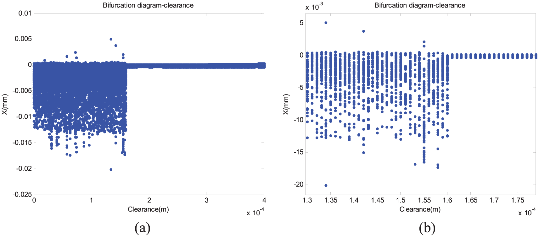
(a) Bifurcation diagram and (b) the local enlarged diagram of (a).

Poincare diagram, clearance: (a) 0.05 mm, (b) 0.18 mm, and (c) 0.96 mm. (a–c) have the same axial ranges.

Orbit of center, clearance: (a) 0.56 mm and (b) 0.96 mm.
Stiffness of the contact
The materials of the rolling element bearings are generally the Ball Bearing Steel Gcr15, the Carbon Steel (20#, 45#), the Stainless Steel (420C, 440C, 304, 302, etc.), the Plastics (Nylon 66#, POM Plastic Steel), the Industrial Ceramic, and so on. Different kinds of materials have the different contact stiffness values K according to equations (10)–(12). Consequently, the effect of the stiffness of the contact between the rolling element and the races on the dynamics characteristics is investigated in this section. The values of the contact stiffness are chosen as 1.4 × 10⁸ N/m, 1.6 × 10⁸ N/m, 1.8 × 10⁸ N/m, 2.0 × 10⁸ N/m, 2.2 × 10⁸ N/m, 2.4 × 10⁸ N/m, 2.6 × 10⁸ N/m, and 2.8 × 10⁸ N/m. The rotating speed is in the span of 0–20,000 r/min; the clearance is 0.02 mm. The corresponding bifurcation diagrams are drawn, as seen in Figure 7(a)–(h). It can be shown from Figure 7(a) that there roughly exist four zones: Zone-A (about 0–0.43 × 10⁴), Zone-B (about 0.43 × 10⁴–0.60 × 10⁴), Zone-C (about 0.60 × 10⁴–1.02 × 10⁴), and Zone-D (about 1.02 × 10⁴–2.00 × 10⁴). Among these zones, Zone-A and Zone-C are periodic or the multi-periodic; Zone-B and Zone-D are quasi-periodic or chaotic. Compared with Zone-A and Zone-C, the responses of Zone-B and Zone-D have a sudden increase, which may put the system on a danger. Therefore, working in Zone-B and Zone-D should be avoided. With the increase in the stiffness, the Zone-C becomes narrow, as seen in Figure 7(a)–(g); and finally the Zone-C even disappears, seen in Figure 7(g); the Zone-A narrows to 0.3 × 10⁴ and then remains unchanged. The Zone-B broadens and finally becomes integrated with the Zone-D, that is, the chaos zone amplifies with the increase in the stiffness. Accordingly, the stiffness has an effect on the distribution of the period—quasi-period—chaos. In engineering practice, the system should be prevented from the operation on the state of the chaos and the critical state from the quasi-period to chaos. It is significant to design the suitable stiffness from the perspective of the safe operation. This work offers an approach to analyze the stiffness to prevent the bearings from the dangerous working conditions.

Bifurcation, stiffness: (a) 1.4 × 10⁸ N/m, (b) 1.6 × 10⁸ N/m, (c) 1.8 × 10⁸ N/m, (d) 2.0 × 10⁸ N/m, (e) 2.2 × 10⁸ N/m, (f) 2.4 × 10⁸ N/m, (g) 2.6 × 10⁸ N/m, and (h) 2.8 × 10⁸ N/m.
Conclusion
In this article, a nonlinear model of the rolling element bearing is developed accounting for the contact state for a rolling element at any moment. The effect of the rotating speed, the clearance, and the contact stiffness on the bifurcation is investigated to analyze the dynamic mechanism of the system. Compared with the related literatures,25–27 some of the nonlinear characteristics of the rolling element bearings agree well, such as the bifurcation, multi-periodic, chaos, and orbit of center; some of the results are characterized by the continuous influence of the clearance and stiffness on the nonlinear characteristics. The main conclusions are as follows:
The dynamic response of the rolling element system is sensitive to the variation of the rotating speed. The system shows the rich and complicated nonlinear dynamic characteristics. In calculation example, the system shows a state of period when the rotating speed is from 0 to 7600 r/min; when the rotating speed is greater than 7600 r/min, the system gradually enters into the state of the quasi-period from periodic and finally into the chaos.
The variation of the internal clearances has an effect on the bifurcation diagram. It is important to choose a proper clearance value for the reduction of the vibration. This study provides an analytical method of designing and verifying the internal clearance of a bearing.
The stiffness has an influence on the distribution of the period—quasi-period—chaos. In engineering practice, the system should be avoided operation on the chaos or the critical state from the quasi-periodic to chaos. It is significant to design the suitable stiffness from the perspective of the safe operation.
Footnotes
Appendix 1
Academic Editor: Crinela Pislaru
Declaration of conflicting interests
The author(s) declared no potential conflicts of interest with respect to the research, authorship, and/or publication of this article.
Funding
The author(s) disclosed receipt of the following financial support for the research, authorship, and/or publication of this article: The authors are grateful for the finance support provided by the National Natural Science Foundation of China under grant number 51305267.