
Abstract
Due to the advantages of stable helical gear transmission, it is widely used in industry, agriculture, and national defense. Shaft misalignment has a great influence on the vibration, bearing capacity, and life of gear transmission. Based on the idler wheel drive system as the research object, according to the principle of gear meshing, the helical gear time-varying contact wire length model was deduced. The dynamic model of the gear transmission system with faults is established considering the faults of the idler's center distance error and angle error, and the influence law of idler misalignment fault on the vibration of the idler transmission system is revealed. On this basis, the finite element model under angle error is established to analyze the contact stress of the tooth surface under different faults and reveal the contact stress distribution law of the tooth surface. The results show that the misalignment fault will change the length of the helical gear contact line. When the gear shaft misaligns, it will increase the axial force of the gear and increase the axial vibration of the gear. Moreover, the angle error will cause uneven load distribution on the tooth surface of the helical gear, which will reduce the contact area of the gear and increase the contact stress. The phenomenon of off-load of gear accelerates the wear of the gear tooth surface and shortens the life of the gear. The study of idler misalignment fault is of great significance for prolonging the life of gear and providing the basis for gear fault diagnosis.
Introduction
Gear transmission is an important part of the mechanical transmission system, with its high precision, high efficiency, good reliability, good durability, strong adaptability, wide speed range, and other advantages, in aerospace, Marine, engineering machinery, industrial robots, and other fields have been widely used, has an important position in the field of machinery. However, due to the large number of teeth in contact with the helical gear at the same time, the sensitivity to error is higher. At present, there have been some research on the fault of misalignment of helical gear. However, there are few reports on the misalignment of three parallel helical gear idlers with idlers.
Choe et al. 1 established the analytical expression of the contact line of helical gear, studied the total length of the contact line and the change interval, and established the change of the contact line length under different helix angles. Kar and Mohanty 2 established the calculation model of the helical gear contact line and analyzed the changes in helical gear contact line length, friction force, and friction torque under normal and broken teeth conditions. Jiang et al. 3 established a dynamic model of 8 degrees of freedom helical gear and analyzed dynamic characteristics such as dynamic meshing force and contact line length considering friction and misalignment.
Farshidianfar et al. 4 studied the nonlinear vibration of a single-stage gear. Different methods are used to solve the kinetic equations, and the results are analyzed in terms of time and frequency. Kumar and Hirani 5 studied the influence of misalignment fault on the failure form of the gearbox through experiments, resulting in bearing cage deformation and rolling body pitting. Arian and Taghvaei 6 analyzed the spur gear transmission system with idler gear, established dimensionless dynamics, considered nonlinear factors such as time-varying stiffness and tooth side clearance, and obtained a phase diagram, Poincare cross-section, and bifurcation diagram through numerical solution. Li 7 studied the influence of tooth profile modification on spur gear meshing. At the same time, the influence of shaft misalignment and transfer torque on gear contact stiffness is analyzed. Yang 8 studied the vibration problem of the system with an idler. Firstly, the dynamic mathematical model is established, the displacement response is obtained by numerical integration, and then the transmission system under heavy load and light load is simulated. Liu and Parker 9 analyzed the nonlinear dynamics of the idler and obtained the stable solution of the equation through numerical and analytical solutions. The stability of resonance and sub-resonance is analyzed. Xu et al. 10 analyzed the influence of misalignment of the bearing raceway on the gear system. The influence of angle, torque, and speed on bearing stiffness is analyzed. Vinayak et al. 11 established a multi-body dynamic model including shaft and bearing. The characteristic solutions of the model are compared with the finite element results, and the results agree with each other. The time-domain and frequency-domain solutions are obtained by the harmonic balance method. Cao et al. 12 analyzed the dynamic response of gears in the case of planetary gear train misalignment. At the same time, the meshing stiffness of the gear is calculated by the potential energy method, and the motion trajectory of the planetary gear train is analyzed. Wang et al. 13 studied the influence of bearing misalignment on the gear transmission system. A dynamic model considering a planetary wheel-bearing rotor system is established, and the dynamic response of bearing misalignment is analyzed.
Jabbour and Asmar 14 mainly studied the contact stress and root bending stress of metal gears, established a mathematical model from the gear processing principle, studied the influence of different parameters on the gear stress, and verified the correctness of the method with finite element analysis. Cazan et al. 15 established a semi-analytical method to consider the distribution of contact stress under shaft misalignment, assembly error, and gear modification. Hwang et al. 16 analyzed the contact stress of spur and helical gears, respectively, studied the contact stress of different contact positions of gears during rotation, and compared the analysis results with the contact stress equation of American Gear Manufacturers Association. Based on the theory of gear design, Mohanraj et al. 17 used numerical analysis and finite element analysis to analyze the tooth surface bending stress of herringbone helical gear and compared the results with the theoretical analysis. The stress distribution of helical gear is determined. Ye and Tsai 18 proposed a new tooth surface contact analysis method for spur gears with a high contact ratio, solved the tooth tip contact phenomenon through side modification, and analyzed the influence of shaft misalignment on the contact mode and stress distribution. Shehata et al. 19 used different finite element software to analyze the influence of misalignment and microscopic modification on gear stress, transmission error, and dynamic response. Liu et al. 20 established the mathematical model of convex and concave tooth surface modification of helical gear. On this basis, the effects of axial error, center distance error, and axial angle error on the contact characteristics of the tooth surface are analyzed. The contact analysis of the tooth surface was carried out by the finite element model. Tiwari et al. 21 studied the meshing of polymer gears under different load and friction conditions, under normal and misaligned conditions. The contact stress of the tooth surface is studied by the finite element method. Zhan and Fard 22 studied the influence of spiral angle, mechanical error, and friction coefficient on the root stress of helical gear through experiments. Due to the misalignment, parallel-axis gears in the transmission process can experience edge contact on the tooth surface. To address this issue, Litvin et al. 23 proposed a new method for the tooth surface topology of helical gears, which improved the gear manufacturing process. The contact stress analysis of the gears was conducted as well. Hotait and Kahraman 24 conducted experimental analysis on the bending stress of gears under misalignment of the gear shaft and tooth surface modification. Meanwhile, different driving torques were applied to the driving gear, and the experimental data were collected to form a database for model validation. Peng et al. 25 established mathematical models for gear tooth modification and misalignment and calculated the tooth surface contact stress based on Hertz contact theory. The distribution of contact stress under different torques and misalignment conditions was analyzed.26–28 Based on gear contact analysis on gear Litvin, a computer program for gear contact analysis was developed to study the influence of helical gear misalignment on bearing contact displacement and transmission error. The results are verified by a numerical example. Karagiannis et al. first obtained the kinematic and geometric characteristics of hypoid gears and then established the dynamic equations to consider the effects of friction and oil film on the gear transmission system. Cazan et al. used a semi-analytical method to study the influence of misalignment, error, and gear modification on gear contact pressure distribution. Sivayogan et al. 29 presented the shear loading of spur gears during the meshing cycle and analyzed the variation of subsurface stresses based on Hertzian contact.
The above research mainly studies the single-stage helical gear transmission system, studies the influence of multiple single faults on the tooth surface stress, establishes the single-stage helical gear dynamic model, and analyzes the dynamic response. The influence of fault on the meshing stiffness of the gear is analyzed. However, there is less research on the integrity of multistage helical gear with idler.
This article takes the idler drive system as the research object, firstly deduces the function relation of contact line length with time. Then a multi-degree-of-freedom dynamic model is established to analyze the vibration response of the misaligned gear transmission system. Finally, the finite element model of idler misalignment is established, and the variation trend of contact stress, contact state, and contact mode of each pair of teeth under different fault sizes are discussed. The distribution law of gear load in the case of misalignment is revealed.
Geometric model of helical gear pair considering error
Take the input wheel and the idler wheel as an example to establish a two-dimensional (2D) model. The helical gear pair with center distance error is shown in Figure 1. The origin of the global coordinate system is located at the geometric center
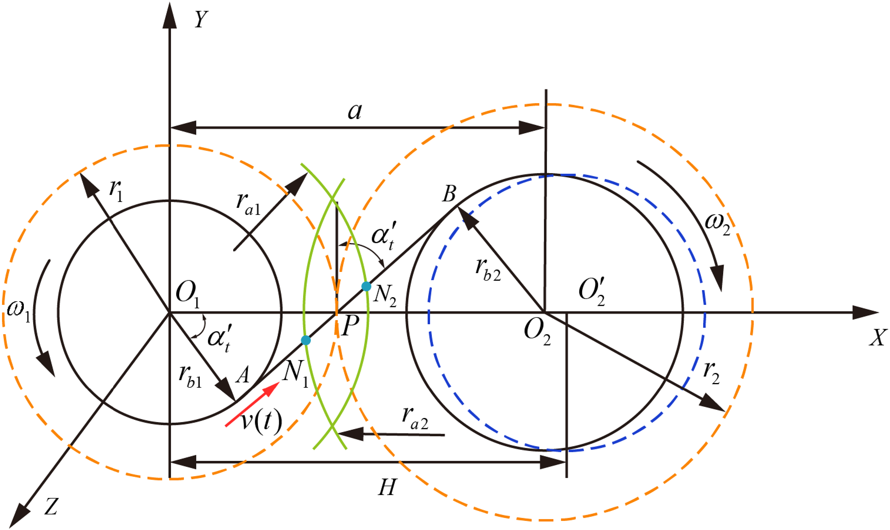
Helical gear geometry model.
The number of teeth of the input wheel is
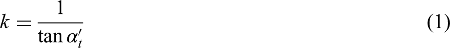
As can be seen from the figure, the slope of the dynamic line of engagement is
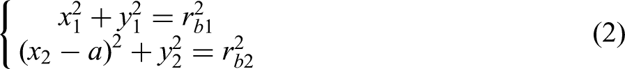
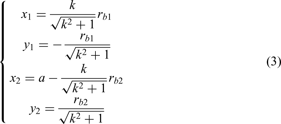
Assuming that the coordinates of two points A and B are (


The meshing line contact in Figure 1 is expanded to the 2D plane, and the meshing line result of the bevel gear without error is shown in Figure 2.
Normal helical gear meshing line diagram.
In Figure 2, b is the tooth width, L1, L2, and L3 are the dynamic line of engagement, and
When the center distance error is caused by improper installation of the helical gear, its meshing line is shown in Figure 3. When the center distance of the helical gear pair decreases, it can be seen in Figure 3(a) that the meshing point
Diagram of the meshing line of helical gear with center distance error: (a) center distance reduction and (b) center distance increases.
Due to the periodicity of gear meshing, the change in the length of the contact line also has periodicity. At time t, the distance between the i and the end face of the gear contact line is expressed as
The length of the contact line
The total length of the line of engagement is
Dynamic model of system with idler
In order to study the dynamic transmission error of the gear transmission system, the multi-degree-of-freedom dynamic model of gear is established by the lumped mass method. In the actual working process, due to the deformation or installation error of bearings and shafts, the vibration forms such as transverse vibration, transverse oscillation, and torsional vibration should be considered in the dynamic model. Coupling between various forms of vibration may also occur. This paper takes Marine retarder as an example and establishes a coupled dynamic system that considers all of the above types of vibration.
The model considers transverse vibration, axial vibration, longitudinal vibration, and torsional vibration. The model is shown in Figure 4. Gear 1 is the input wheel, gear 2 is the idler wheel, and gear 3 is the output wheel. Where the displacement of the system is expressed as
The dynamic model of the gear transmission system.
In the formula,
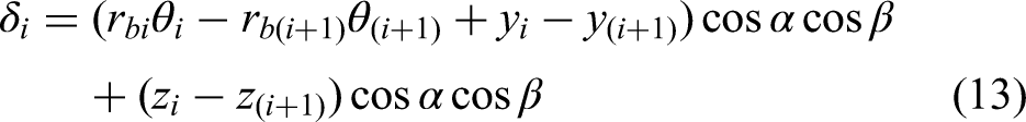
The elastic deformation between the input wheel and the idler wheel and between the idler wheel and the output wheel can be expressed as
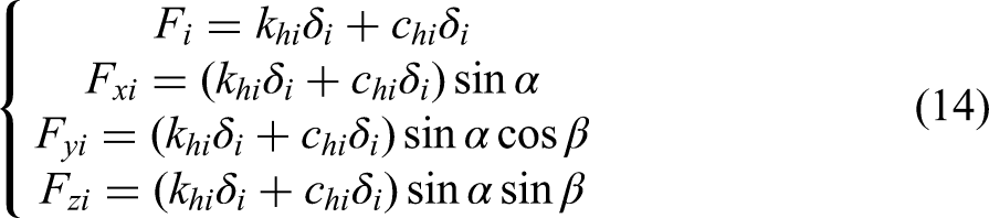
The meshing force of the gear transmission system and the component force in each direction30,31 are
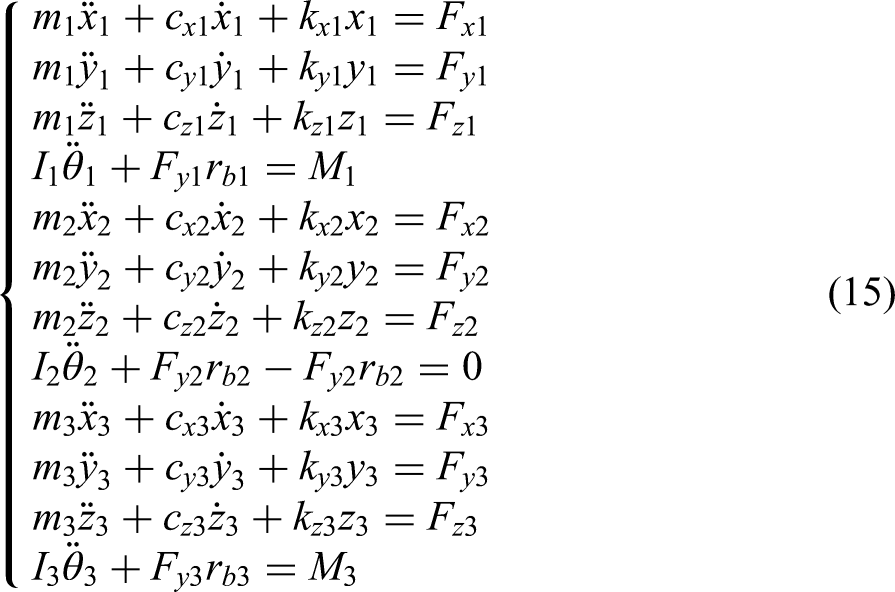
According to Newton's second law, a dynamic model considering time-varying meshing stiffness and installation error is established
Examples and analysis of results
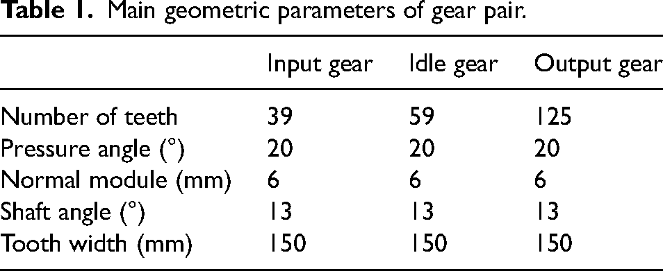
In the “Geometric model of helical gear pair considering error” and “Dynamic model of system with idler” sections, the time-varying theory of the helical gear contact line and the dynamics of the helical gear system are analyzed, respectively. Then, the time-varying curves of the helical gear contact line with center distance error and angle error are calculated by numerical solution, and the vibration equation of the gear transmission system is solved by the fourth-order Runge-Kutta method. Table 1 shows the main parameters of the gear pair of a Marine reducer.
Main geometric parameters of gear pair.
Contact line analysis with different errors
Figure 5 shows the contact path of the idler under normal conditions. Under ideal conditions, the contact pressure per unit length of each contact line is the same. Based on this, the contact line length of the helical gear is calculated. Figure 6 shows the change of contact line length with time under center distance error and angle error, respectively. As can be seen in Figure 6(a), when the deviation of center distance causes the actual center distance to be greater than the theoretical center distance, the length of the meshing surface and contact line of the helical gear will change, resulting in the change of the contact degree of the helical gear. With the increase of center distance, the contact degree of the end face of the gear will decrease, shortening the meshing time. As can be seen in Figure 6(b), when there is no parallel angle between the two axes of the gear transmission system, the contact line of the helical gear will also change. With the increase of the included angle, the length of the contact line will decrease in turn during the meshing process.
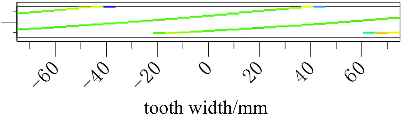
Contact path.
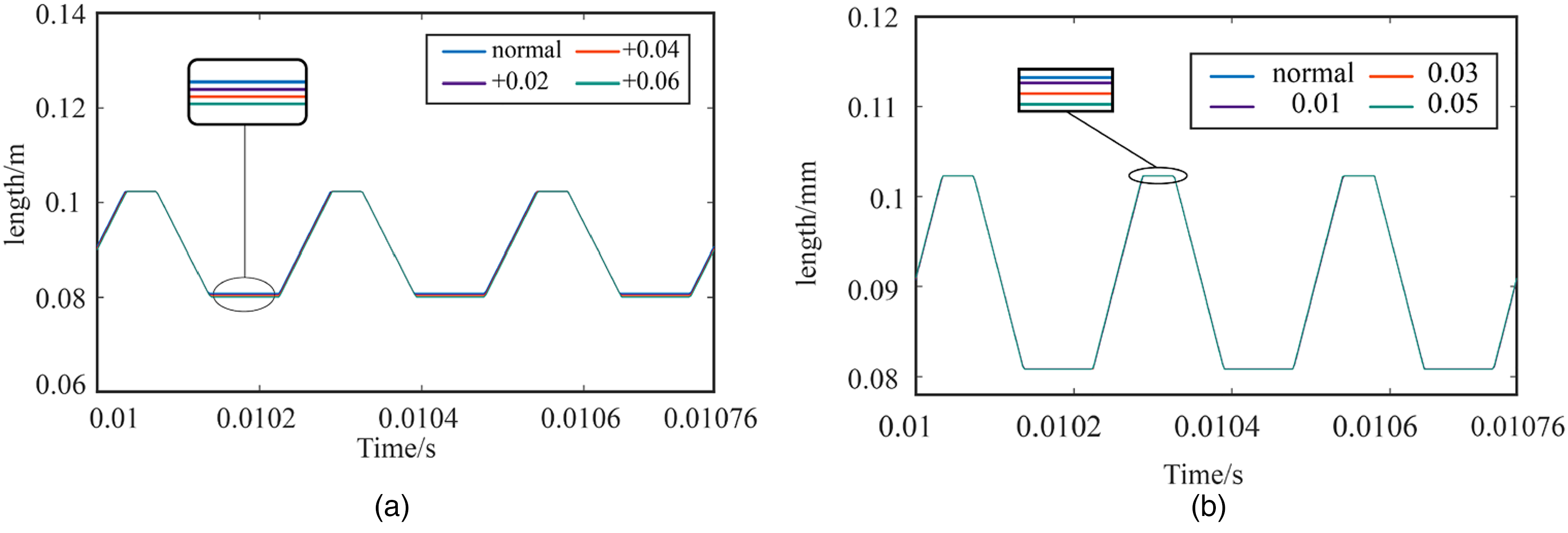
Contact line error for different faults: (a) length of contact line under different center distance error and (b) contact line length under different angle error.
Study of vibration characteristics under different errors
Figure 7 shows the frequency domain response of dynamic transmission error between the input wheel and the idler wheel and between the idler wheel and the output wheel when the idler wheel has different angle errors. Because the idler is in direct contact with the input wheel and the output wheel, the dynamic transmission error between the two wheels will change when the idler fails. The first-order vibration amplitude changes from 4.065 × 10⁻⁶ to 4.066 × 10⁻⁶, and the second-order vibration amplitude changes from 3.2784 × 10⁻⁶ to 3.2788 × 10⁻⁶.
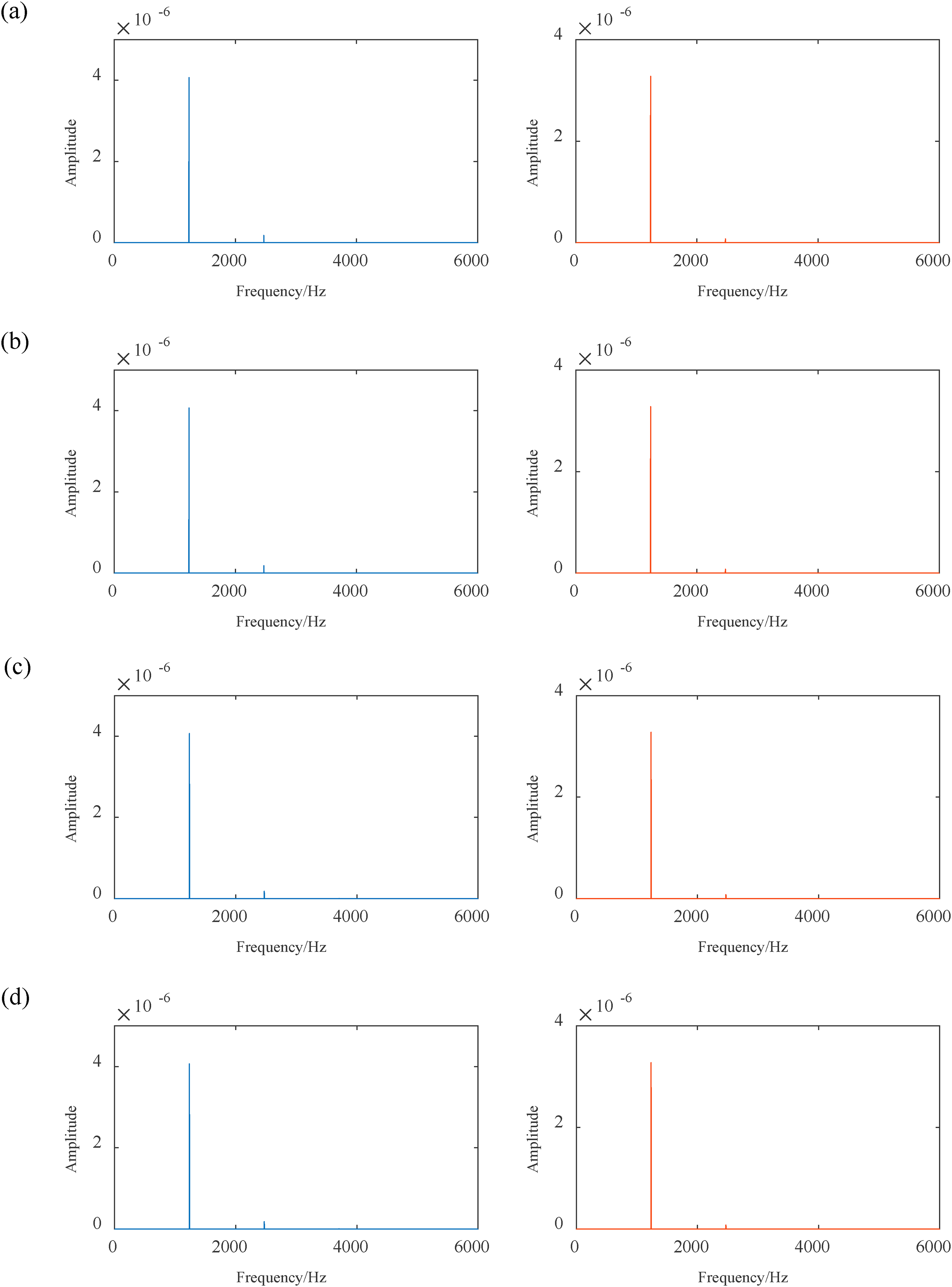
Frequency domain response of dynamic transmission error under angle error (a) normal, (b) angle is 0.01, (c) angle is 0.03, and (d) angle is 0.05.
With the increase of the angle between the idler wheel and the input wheel and the output wheel, the dynamic transmission error between the two wheels increases gradually. The vibration of the gear transmission system increases.
Figure 8 shows the vibration displacement frequency domain response of each gear in the axial direction when the idler has an angle deviation. It can be seen from the figure that the axial displacement of the idler changes obviously, and the axial vibration amplitude increases gradually with the increasing of the deviation angle. Under normal circumstances, the amplitude of the frequency domain is 4.58 × 10⁻⁸, 4.13 × 10⁻⁷, and 1.14 × 10⁻⁷. When the angle is increased to 0.05°, the vibration amplitude is 4.60 × 10⁻⁸, 4.15 × 10⁻⁷, and 1.15 × 10⁻⁷.
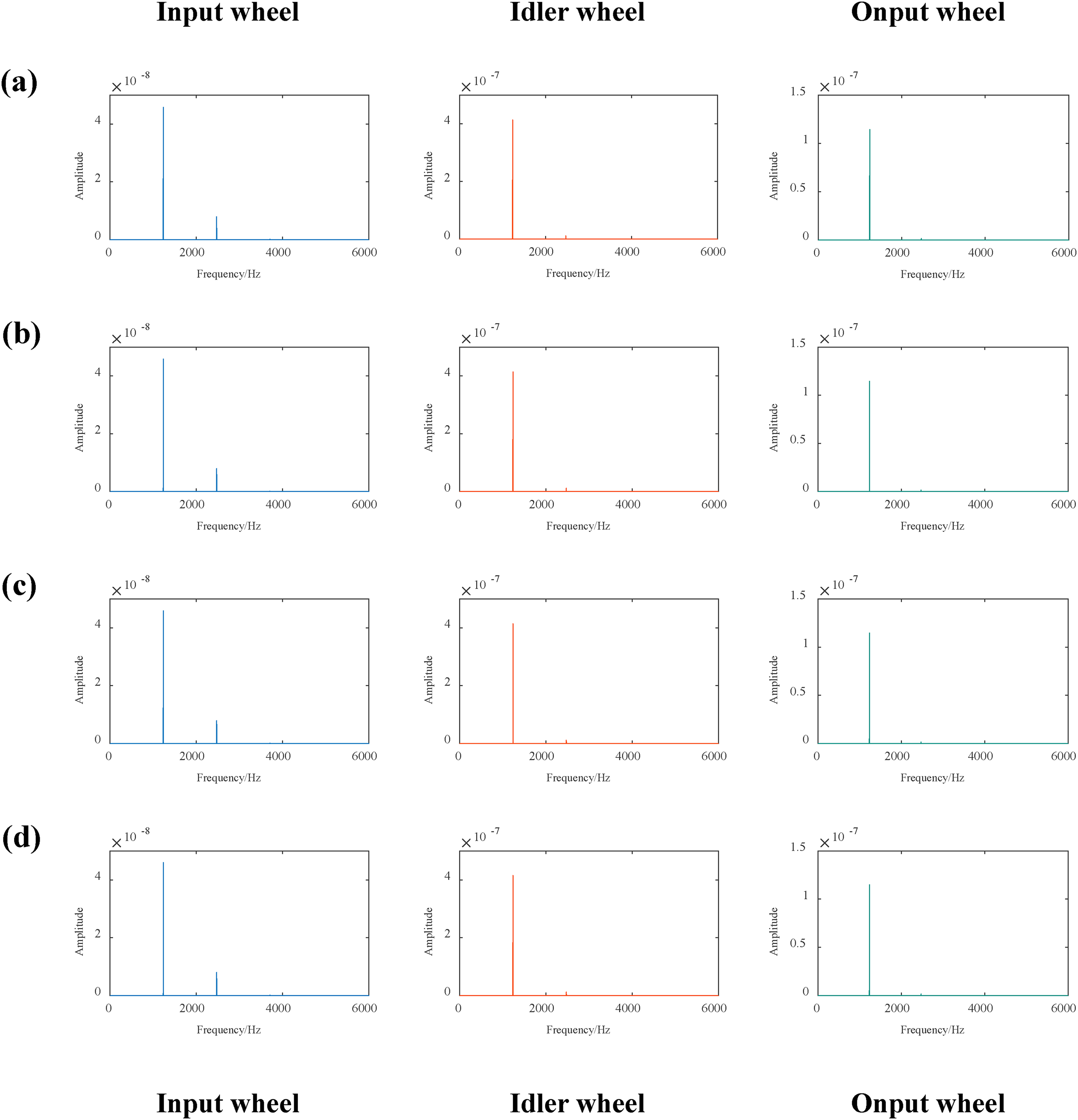
Frequency domain response of vibration displacement in the z-direction (a) normal, (b) angle is 0.01, (c) angle is 0.03, and (d) angle is 0.05.
Contact stress analysis with misalignment error
The influence of the change of contact state caused by the misalignment error on the contact stress distribution of gear is analyzed by the finite element simulation method. The influence of misalignment error on contact characteristics is studied. The finite element model of the gear transmission system was established according to the gear meshing principle, and the size of the misalignment error was considered in the model.
Figure 9 shows the finite element model of the gear drive input wheel and idler wheel, in which a 20-node hexahedral element solid186 is used to mesh gear pairs. In order to accurately calculate the contact stress of the helical gear, this article assumes that the idler drive system is carried out at room temperature, and the contact form between the gear teeth is frictional contact, in which the friction coefficient is 0.15 and there is no lubrication. The contact stress of the tooth surface is calculated based on Hertzian theory. The contact pressure is elliptic on the contact surface, and the surface stress is semi-elliptic.
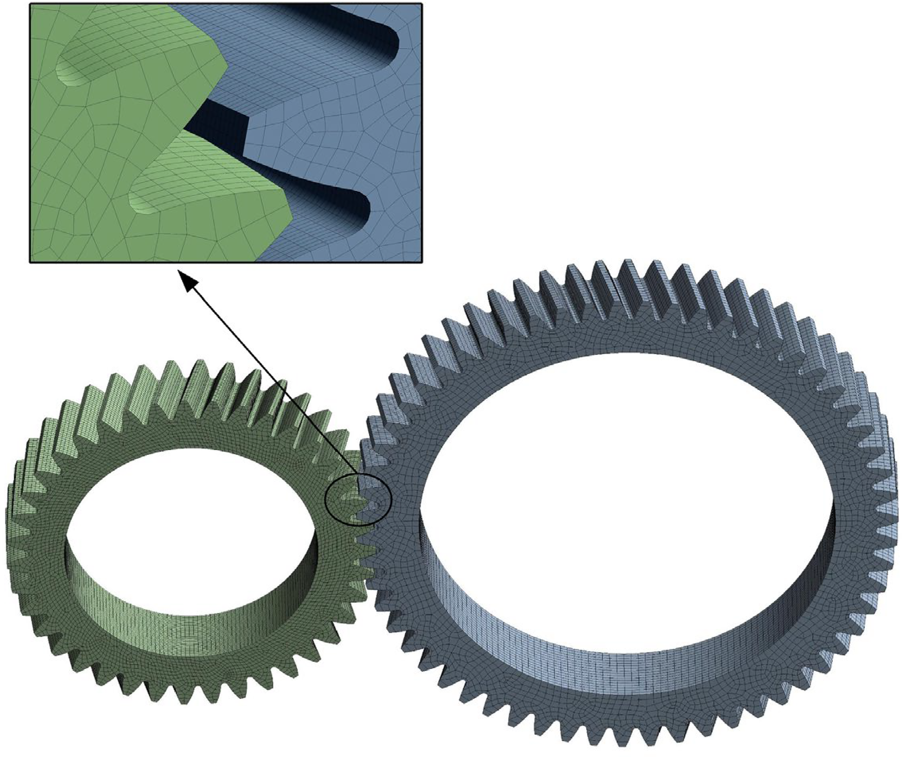
Finite element model of the gear transmission system.
In order to study the contact form of the gear transmission system, the contact stress of the tooth surface, and the bending stress of the tooth root when the angle deviation of the idler occurs, the finite element simulation analysis of the gear transmission system is carried out. Figures 10 and 11 show the contact stress of the tooth surface of the idler under different angle deviations and the change of the contact line of the helical gear. As can be seen in Figures 10 and 11, with the continuous increase of the idler angle deviation, the contact form of the tooth surface changes, and a partial contact phenomenon appears on the entire tooth surface, which greatly changes the distribution of load along the tooth width direction, resulting in more significant vibration of the dynamic response of the helical gear. At the same time, the increase in the angle is equivalent to the increase of the helical angle of the helical gear, and the increase of the helical angle will increase the axial vibration of the helical gear.
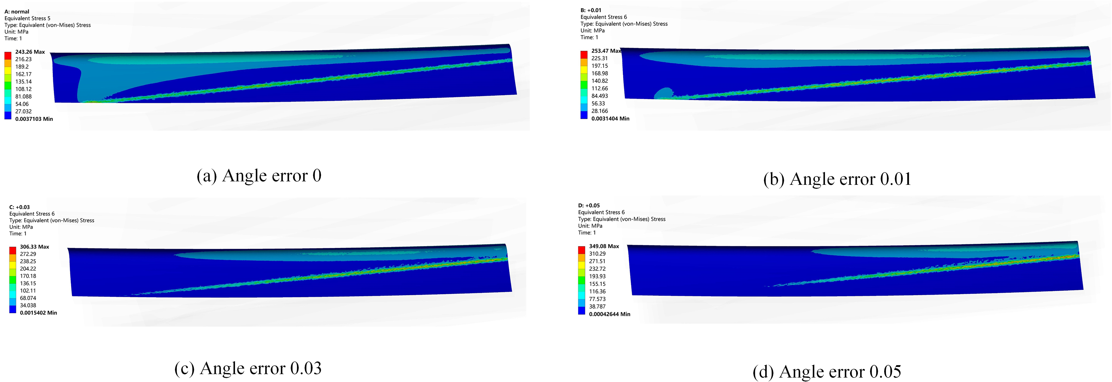
Misalignment error contact stress (input wheel and idler wheel).
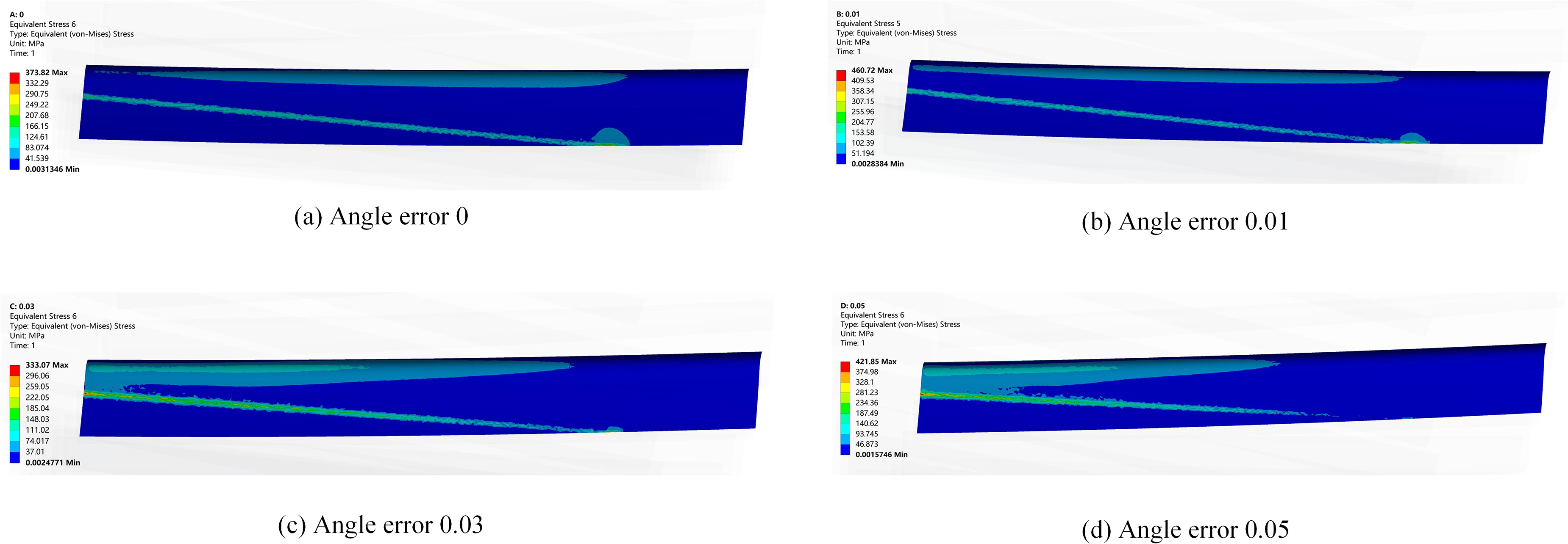
Misalignment error contact stress (idler wheel and output wheel).
Figure 12 shows the change of tooth surface contact stress when the idler angle error occurs. With the increase of angle error, the contact stress continues to increase. It can be seen in Figure 13(a) that when the angle changes from 0° to 0.05°, the contact pressure changes from 158 to 349 Mpa, an increase of 120%. It can be seen in Figure 13(b) that the contact pressure changes from 155 to 421 Mpa, an increase of 172%. It can be seen that the angle error will increase the contact stress of the tooth surface and shorten the life of the gear.
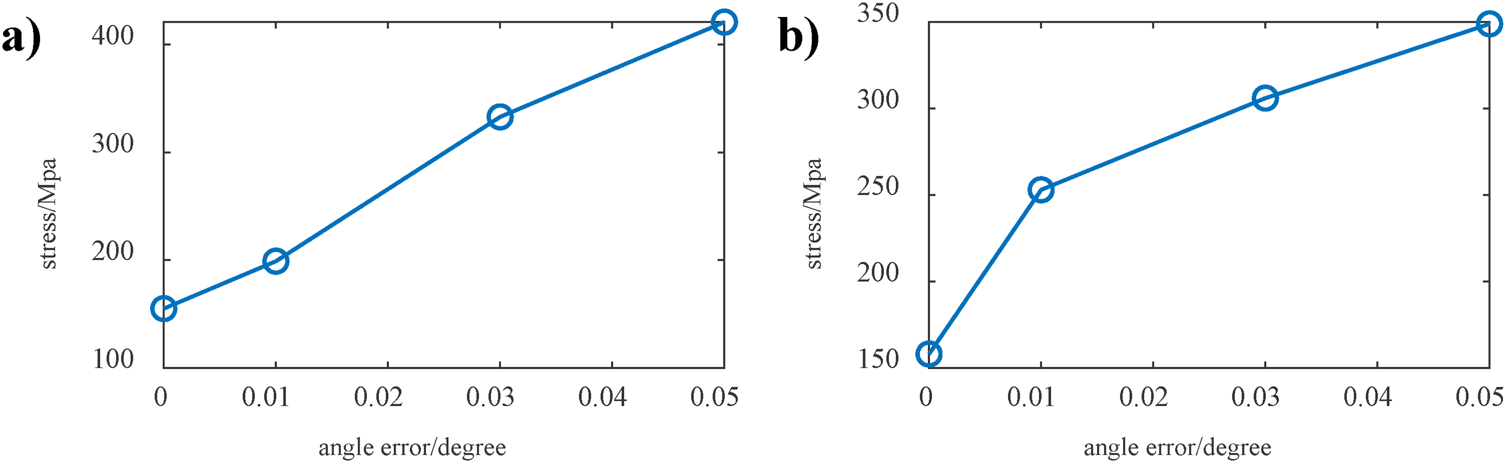
Idler tooth surface stress curve.
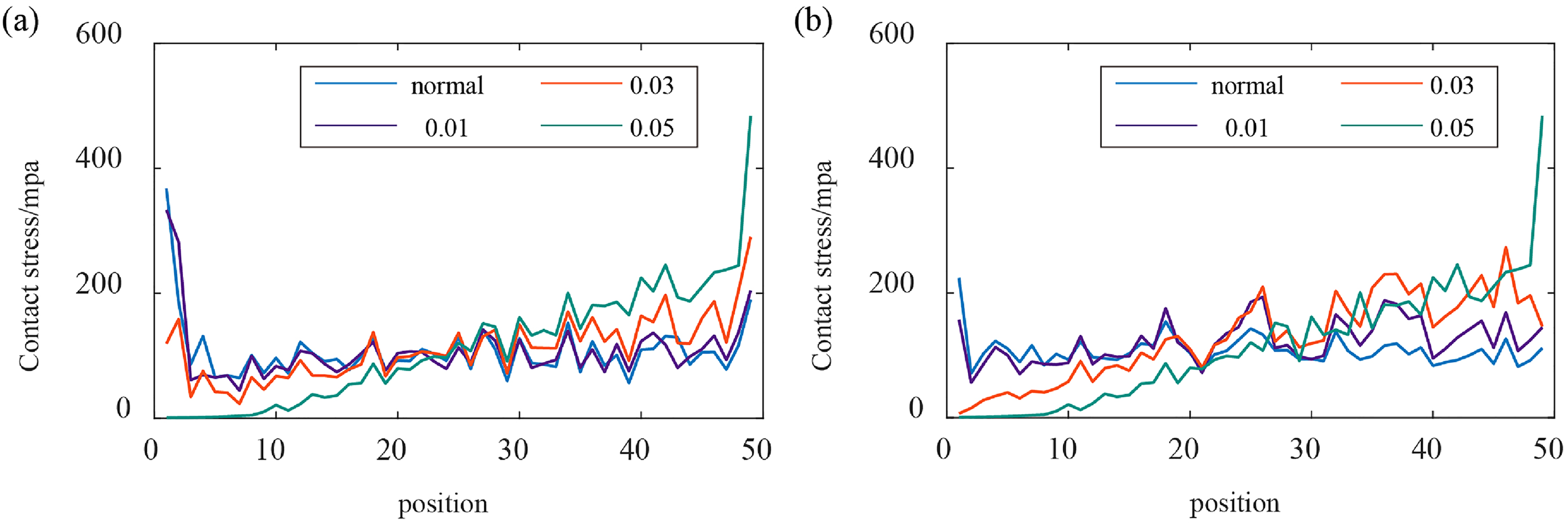
Stress at different positions of the contact line (a) input wheel and idler wheel (b) idler wheel and output wheel.
Figure 13 shows the stress value of the contact line. The length of the contact line is divided into 49 parts and the contact stress at the point is extracted respectively. Where the blue line is the contact stress of the tooth surface under normal conditions, the shape of the line is the shape of the bathtub with high sides and low middle, and the load distribution of the gear is uniform. When the idler angle error occurs, due to the incomplete contact of the gear, the contact stress of the gear increases and the contact of part of the tooth surface becomes more obvious with the continuous change of the angle. As can be seen from the green line in Figure 10, the contact stress at the 10 points from 0 to 10 is almost 0, and the contact stress caused by the angle error at the end is greater.
In order to analyze the subsurface stress of gear under normal and fault conditions, the data of gear end face stress are extracted and plotted. As can be seen in Figure 14, there is a certain distance between the subsurface stress and the tooth surface of the gear. Moreover, when the gear fails, the subsurface stress of the gear increases, from 352 to 409 Mpa.
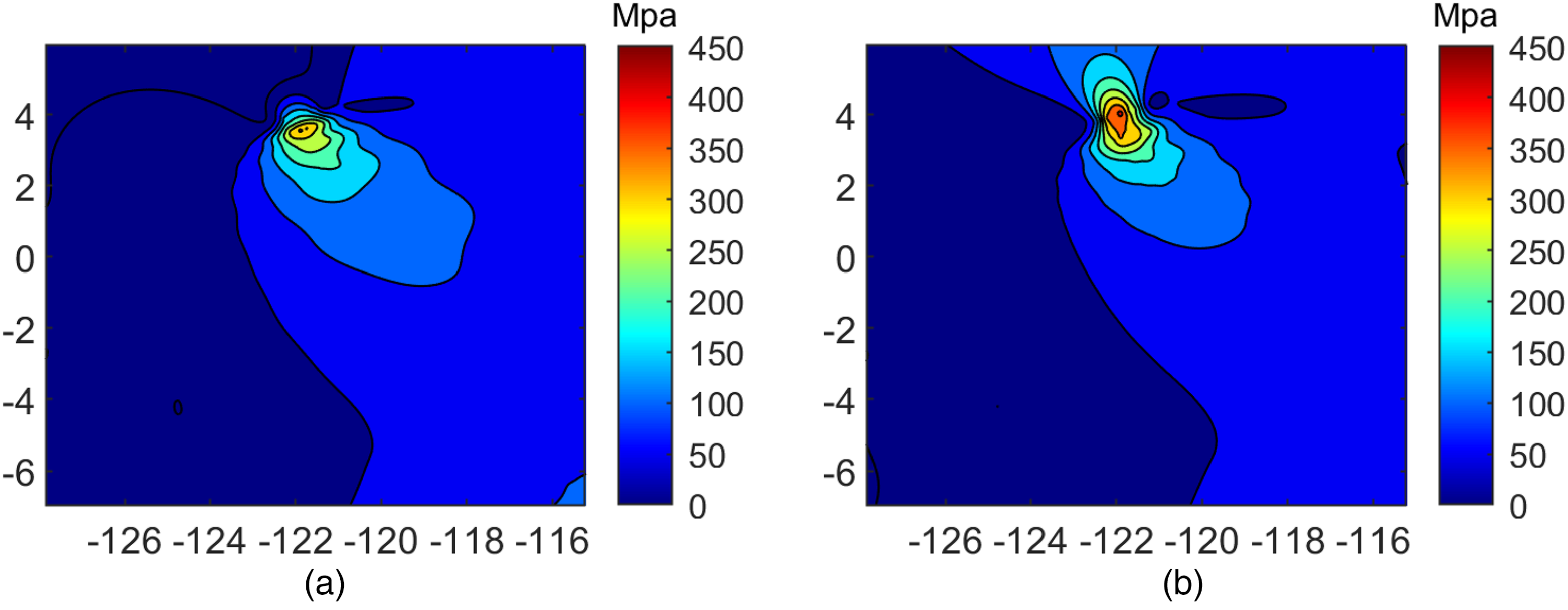
Diagram of gear sub-surface stress.
Conclusion
The article establishes a dynamic model for the idle gear transmission system based on the gear meshing principle. Considering the misalignment, it discusses the variation of the gear contact line and analyzes the vibration response under the misalignment fault of the idle gear, revealing the vibration characteristics. Then, a finite element model for helical gears is established to study the variations of contact stress and contact lines caused by different angular errors. The article analyzes the distribution of tooth surface loads and explores the trends of subsurface stress variation in gears.
The change of the length of the contact line of the helical gear under normal state and fault state is analyzed. When the center distance error and angle error increase, the length of the helical gear contact line will decrease. The dynamic model under the fault state is solved and the transmission error between gears and the axial displacement of each gear are analyzed. In the case of an angle misalignment fault, the change of axial displacement of the idler wheel is the most obvious. With the increase of fault, the transmission error between gears also increases, and the vibration of the gear transmission system will increase. Comparing the contact stress of the tooth surface under normal conditions and fault conditions, the contact stress of the tooth surface under normal conditions is evenly distributed, but the contact stress of the tooth surface under angle error is unevenly distributed, and the gear is biased. With the increase of the fault, the tooth surface appears partial contact phenomenon, and the tooth surface stress distribution becomes a slope distribution.
Footnotes
Declaration of conflicting interests
The author(s) declared no potential conflicts of interest with respect to the research, authorship, and/or publication of this article.
Funding
The author(s) disclosed receipt of the following financial support for the research, authorship, and/or publication of this article: This work was supported by the National Natural Science Foundation of China (grant number 51775036).