
Abstract
Active rear steering has been used in many research work to enhance ground vehicles’ lateral stability. However, there is a shortage in the published research studies that consider the incorporation of active rear steering for autonomous vehicles applications, especially in case of multi-axle combat vehicles. In this paper, various H∞ controllers are developed to actively steer rear axles of a multi-axle combat vehicle using a linearized bicycle model. The proposed controllers are incorporated with a 22 degrees of Freedom nonlinear Trucksim full vehicle model to study and compare the developed controllers’ performance on a hard surface. Moreover, a frequency-domain analysis is conducted to investigate the influence of the active rear steering on the path-following controllers’ robustness in terms of stability and performance. Three path-following controllers are designed, where the first controller is applied on the front two axles of the vehicle, while the rear two axles are fixed. The second is applied to all-wheel steering vehicle. The third controller is an integration between the designed front steering path-following controller and a developed lateral stability active rear steering controller. Eventually, a series of virtual maneuvers are performed to evaluate the effectiveness of the intended controllers to present the advantages and limitations of each controller at different driving conditions.
Keywords
Introduction
In the past two decades, safety demand has been increased in automotive engineering. Therefore, several safety controllers have been introduced to meet this requirement. Examples of these systems are anti-lock braking systems, electronic stability control, lane-keeping assist, active suspension, and torque vectoring control. Generally, the vehicle’s lateral, longitudinal, and vertical dynamics are controlled by these systems. However, in case of avoiding a crash or performing severe maneuvers, controlling the lateral stability is more beneficial. There are two strategies are used to enhance the vehicle lateral stability. The first is direct yaw moment control1–5, while the second is active steering control, which can be performed using active front steering6–9 and/or active rear steering (ARS) systems10,11.
In general, ARS has more effectiveness in lessening the vehicle sideslip than other methods and increases the vehicle stability12,13. However, ARS is still not common in passenger vehicles because the continuous use of it delivers noise as driving with flat or snow tires beside a feeling that the vehicle points out from turning curvature
14
. Meanwhile, ARS seems to be more efficient for military combat vehicles as it works in a harsh environment, so noise will not be an issue, and it requires a trained driver to operate it. Despite that, limited studies considered ARS to improve lateral stability of combat vehicles as in15–17 and in18,19 for a 6x6 and
Recently, the research related to autonomous vehicles has great attention to prevent human errors and risking human lives in dangerous applications as in the military field 20 . For developing an autonomous vehicle, path-following is an essential task to execute the vehicle’s motion on a desired path or trajectory. As for the past decade, path-following was limited to the front steering by actively steer the front axle to track the desired path as in21,22. Recently, it was found that constraining the vehicle yaw rate and sideslip can enhance the tracking performance at high speed as in23–25. Also, it was found that including the control of the wheels’ driving torque inside the path-following controller is beneficial in controlling the vehicle dynamics and consequently improve the high-speed tracking performance as in26–31.
Still, there is a gap in the literature regarding the consideration of ARS in path-following applications, especially for multi-axle vehicles. Moreover, there is a lack in introducing a path-following controller for ground multi-axle vehicles in limit handling conditions for severe maneuvers. Therefore, the main contribution of this study can be summarized as follows:
Include the steering of the rear axles in the path-following controller’s design in two different forms and compare their performance; all-wheel steering (AWS) path-following controller and front wheel-steer path following controller combined with a lateral stability ARS controller. Investigates the effect of including the steering of the rear axles on tightening the controller’s design requirements and robustness against the velocity variation. Fill the gap in the literature and introduce a path-following controller based on ARS for a multi-axle combat vehicle. Enriches the shortage in the published research work related to automation of multi-axle combat vehicles.
Studying the path-following performance of combat vehicles on soft soil (off-road operation) requires a detailed tire–soil interactions model32–35. In addition, the lateral dynamics of the vehicle will not only dependent on the vehicle parameters, but also the soil mechanical properties36,37. This study is focusing on the path-following performance on a hard surface (on-road). The off-road operation analysis on soil will be included in future work.
In this paper, three cases of the path-following controller are developed and compared for an
Mathematical model
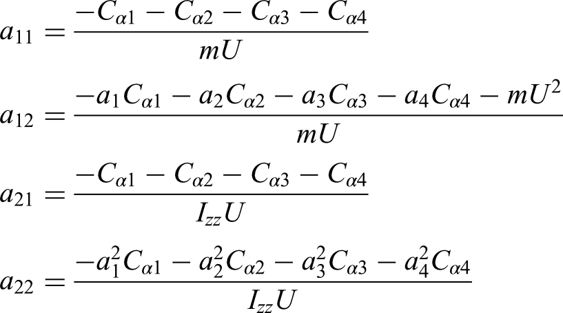
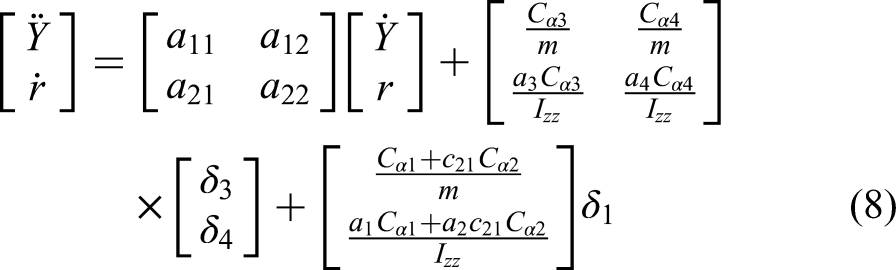
The bicycle model showed its effectiveness to design a lateral stability controller in previous studies as introduced by4,9,38,5,13,39,40. Besides, it is also used for vehicles’ automation and path-following applications as presented in31,25,29,24. Therefore, the state-space model required to design the controllers can be derived using a linearized 2 degree of freedom (DoF) bicycle model for the
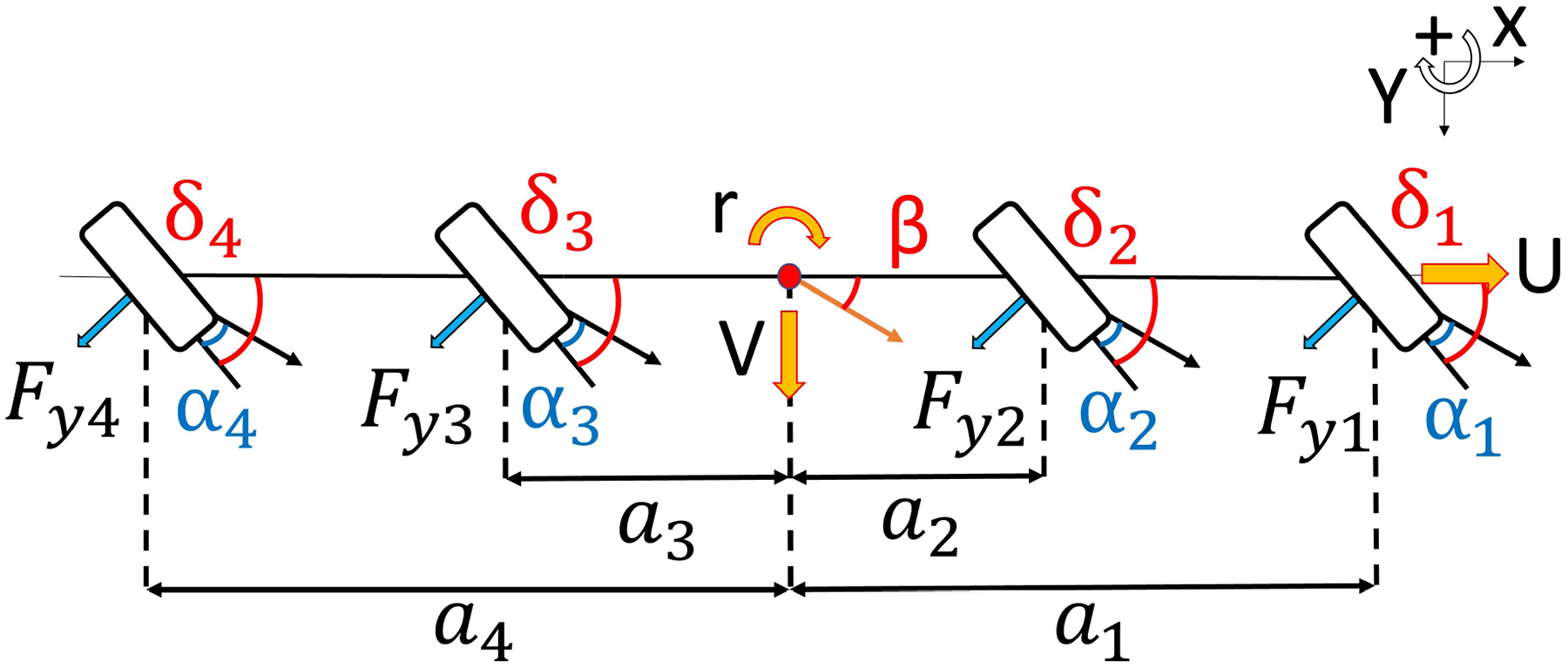
All-axles steering
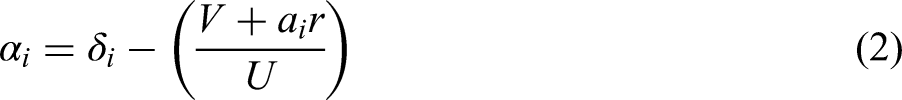
The state-space model is developed to control the vehicle’s heading angle, lateral position and speed, and yaw rate. The model is linearized based on the following assumptions:
Negligible longitudinal and lateral load transfer. A small angle approximation is used. All tires are identical. Linear tires characteristics on hard surface (no off-road analysis). Wheels’ camber, tow, and caster angles are neglected. Constant longitudinal speed.
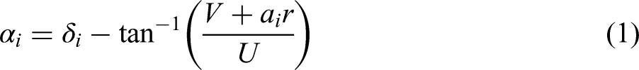
The tires’ slip angles


Controllers design
This section introduces the procedures that are used for developing the controllers using H∞ control theory. The section starts with a brief about the control theory followed by a structure of the weighted and augmented plant.
H∞ path-following controller
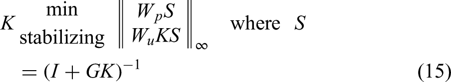
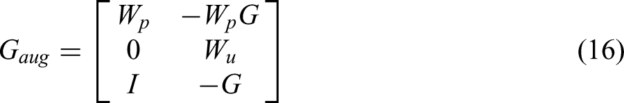
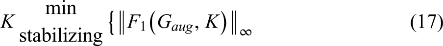
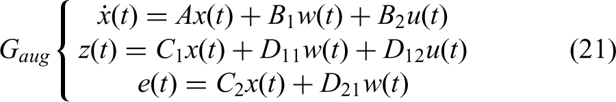
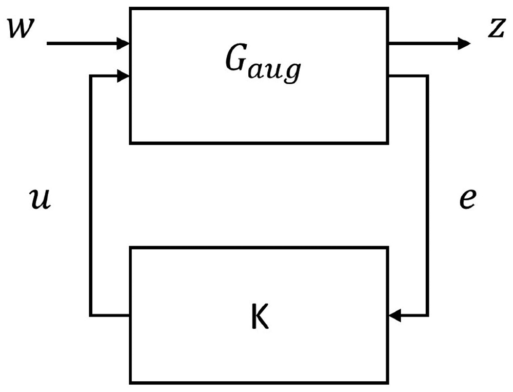
In general, H∞ control design is based on minimizing the H∞ norm of the lower fractional transformation

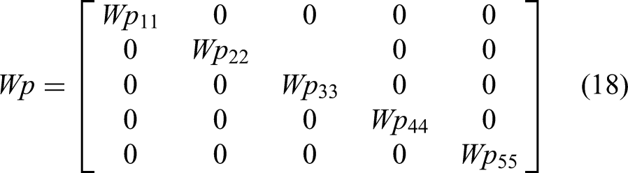
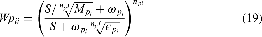
Equation (19) present the performance weight function.
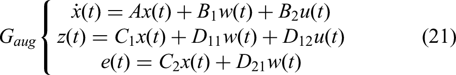
Controller block diagram of the augmented plant.
H∞-ARS lateral stability controller
The same theory and structure of the path-following controller are applied for the lateral stability controller. However, the controlled states and consequently the performance weights are decreased into two (
Controllers’ implementation
This section introduces the design procedure and design requirement limitations for each control case. The design includes the performance and control weighted functions that are selected and tuned to satisfy an accepted range for stability and performance. Moreover, a frequency domain analysis is conducted to demonstrate the performance and stability robustness against the velocity uncertainty.
Front steering path-following controller
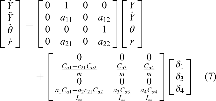
Equation (7) is used to design the controller, where the steering of the
Path-following controllers' design parameters.
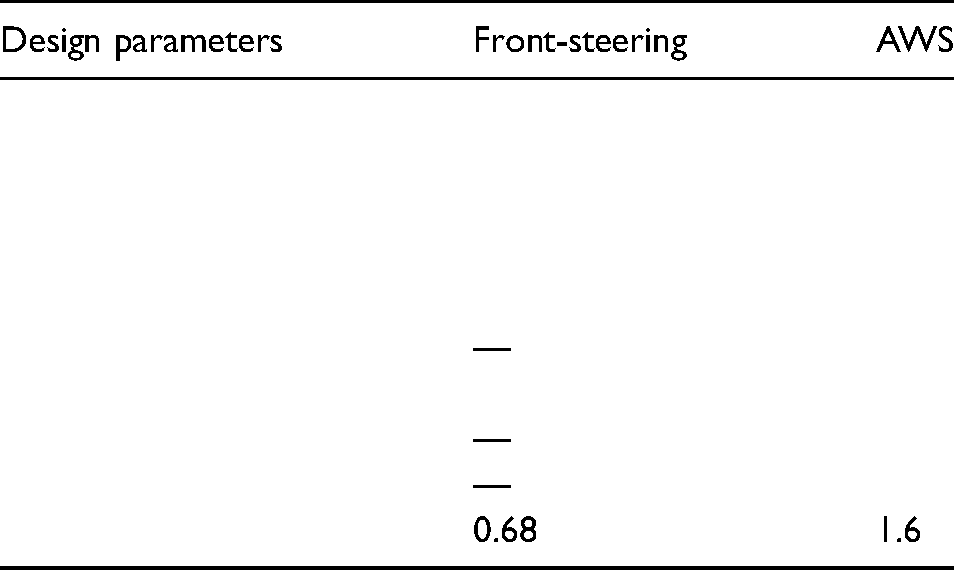
Figure 3 presents the frequency analysis of the uncertain CLS for the determined controller. Figure 3(a) shows that the output lateral position satisfies the designed performance weighted function
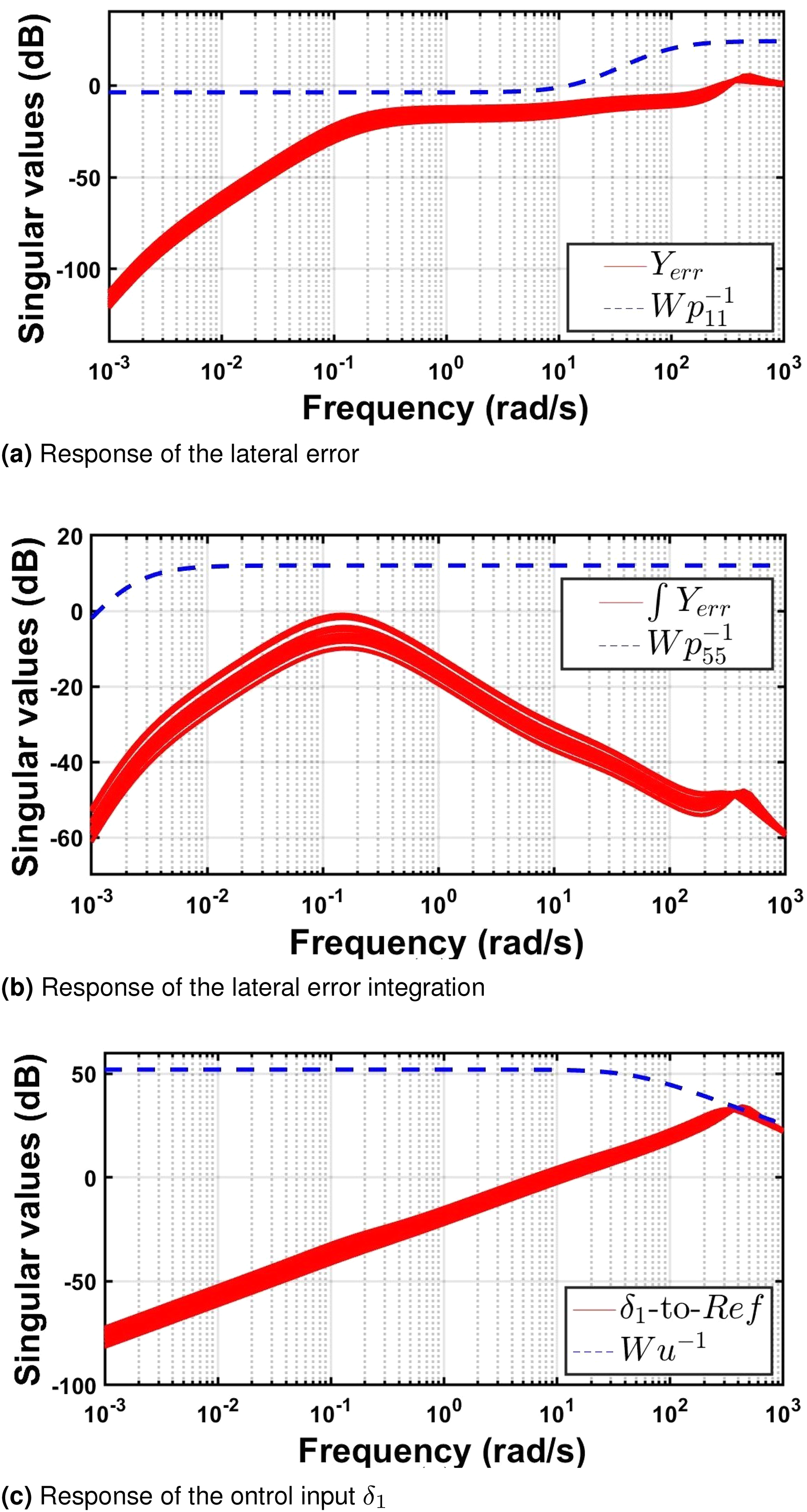
CLS frequency response to the reference inputs. (a) Response of the lateral error, (b) response of the lateral error integration, and (c) response of the ontrol input
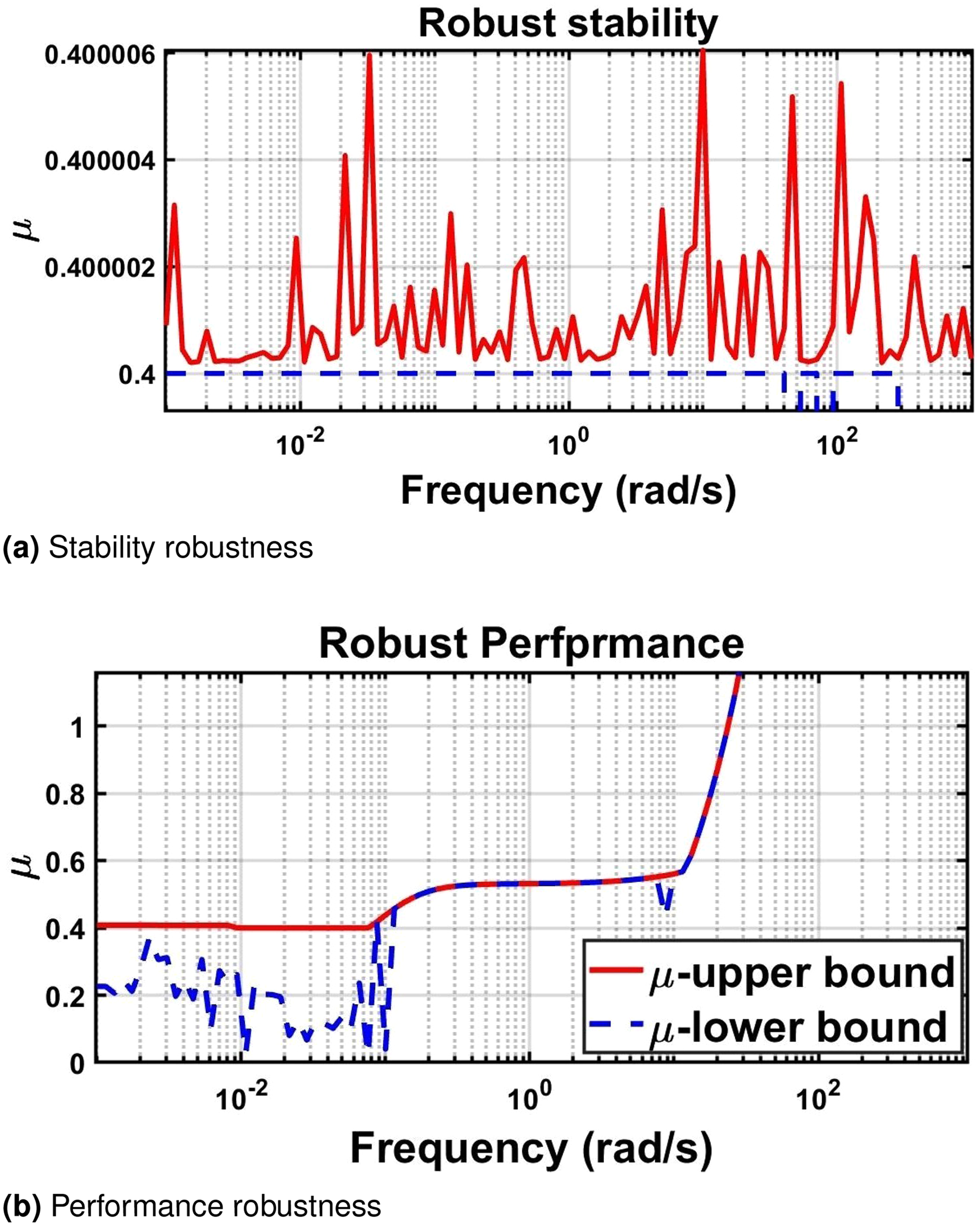
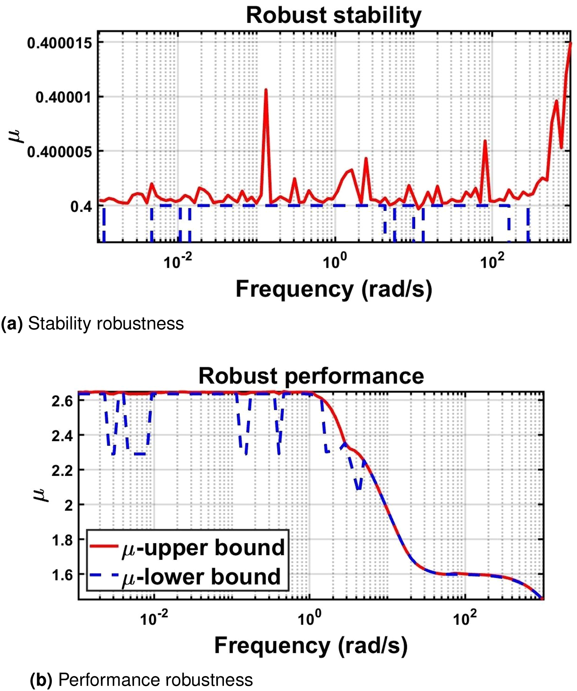
Robustness of the front steering CLS. (a) Stability robustness and (b) performance robustness.
AWS path-following controller
Equation (7) is used with no modifications to design the AWS path-following controller that utilizes the steering of the
The optimizer was able to find a solution considering the velocity uncertainty at nominal forward velocity Tightening the constrains on the lateral error by increasing the gain of Adding constrain on the heading angle tracking error at low frequency ( Increasing the constrain on the lateral error integration weight function Penalizing the heading angle tracking error integration at low frequency, as shown in Figure 5(d), to ensure a zero steady-state heading angle at the end of the maneuver by adding the weighted function Penalize the control inputs maximum steering angle at high frequencies, as shown in Figure 6.
Despite the advantages of adding the steering of the rear axles on the design procedures, the CLS achieves robust stability but lacks performance robustness, as can be concluded from Figure 7(a) and (b), respectively. However, by observing Figures 5 and 6, it can be noticed that the violation of the performance requirements is in an acceptable range and still, can achieve good performance.
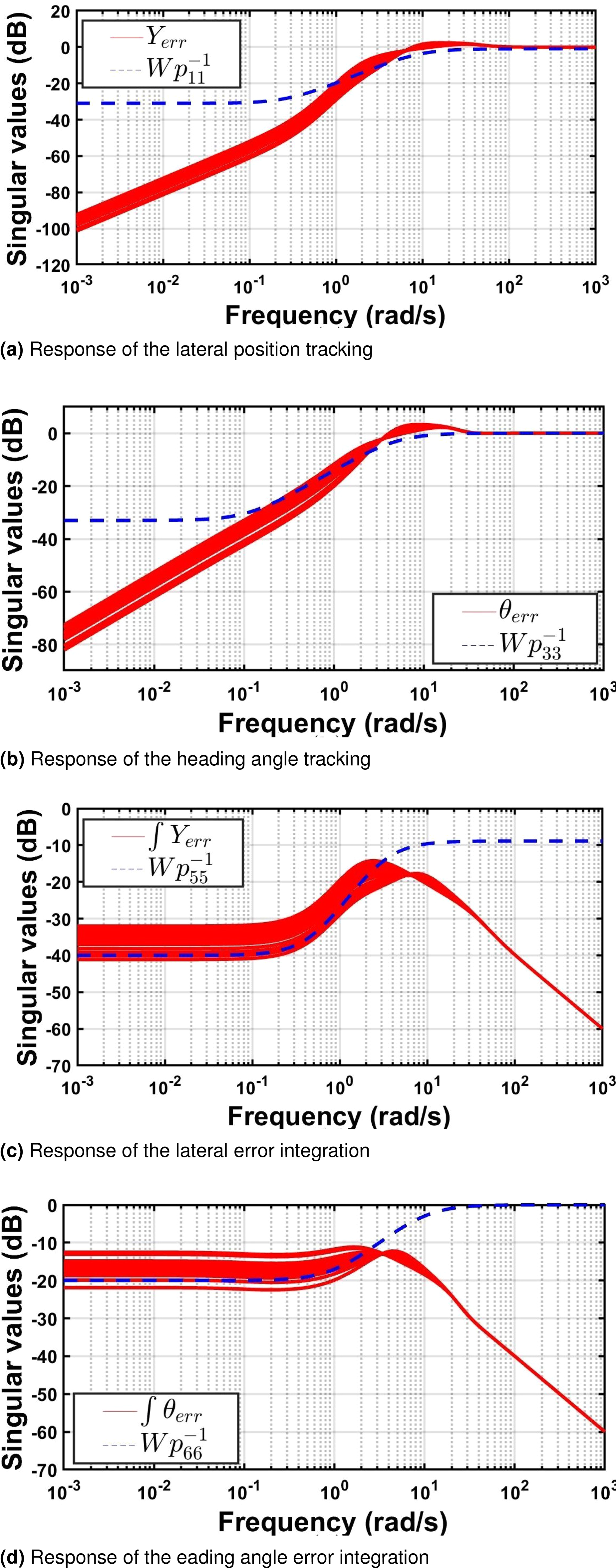
CLS frequency response. (a) Response of the lateral position tracking, (b) response of the heading angle tracking, (c) response of the lateral error integration, and (d) response of the eading angle error integration.
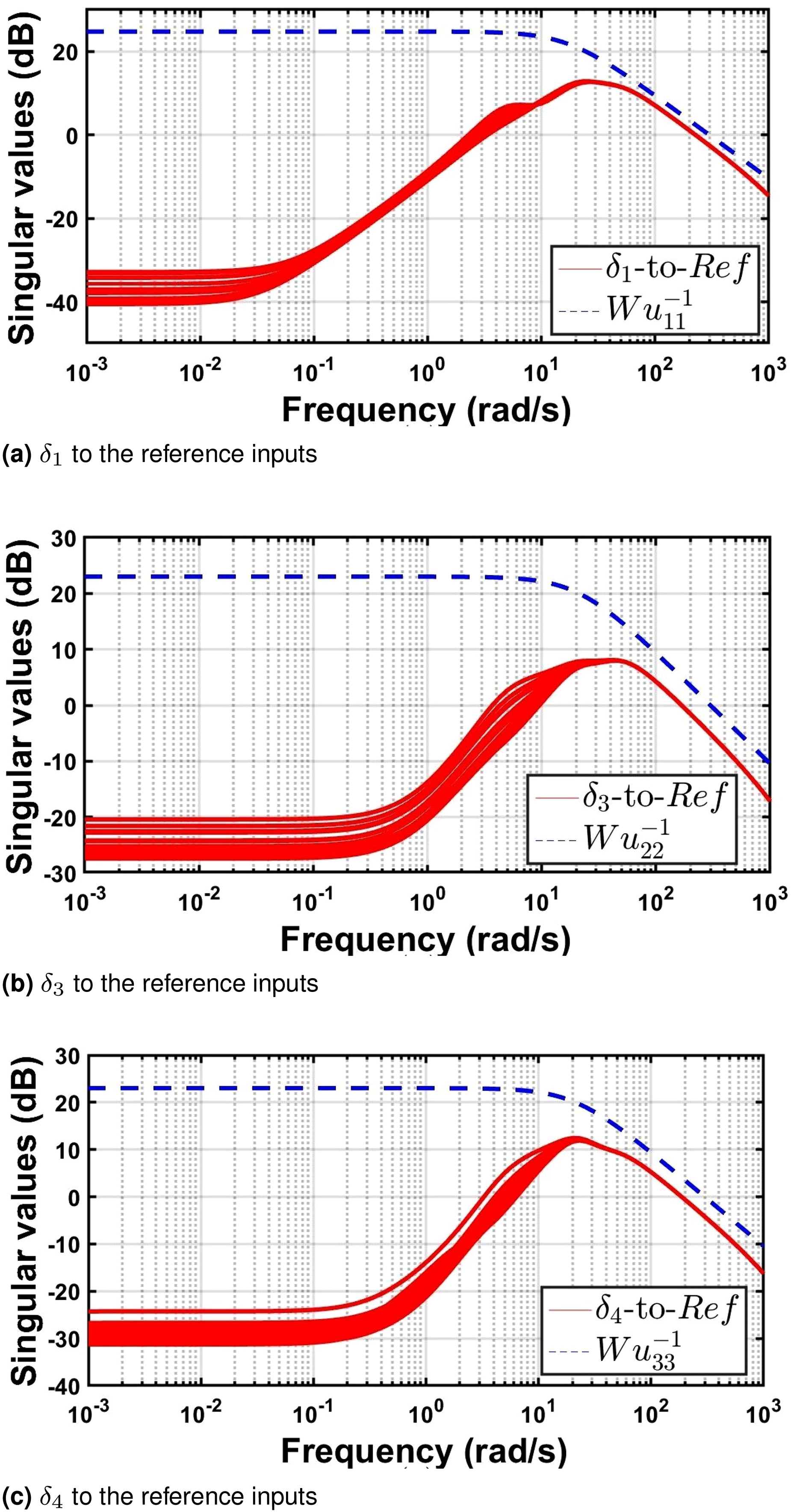
CLS frequency response of the control input. (a)
Robustness of the front steering CLS. (a) Stability robustness and (b) performance robustness.
ARS lateral stability controller
In this section, an H∞-ARS lateral stability controller is developed to be integrated with the front steering path-following controller. The controller is developed to penalize the vehicle’s lateral velocity and consequently limits its sideslip and improves the stability while performing steering. The performance and control weighted functions of the developed ARS are presented in Table 2.
Lateral stability controller's design parameters.
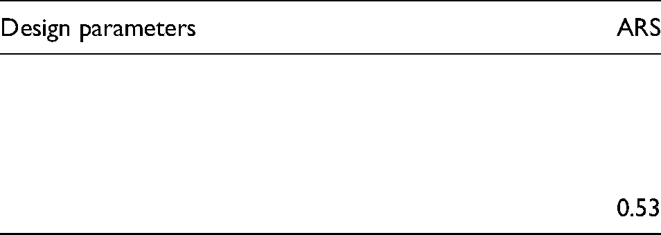
Figure 8 presents the frequency response of the CLS, where Figure 8(a) shows the lateral velocity response and Figure 8(b) and (c) shows the response of the control inputs
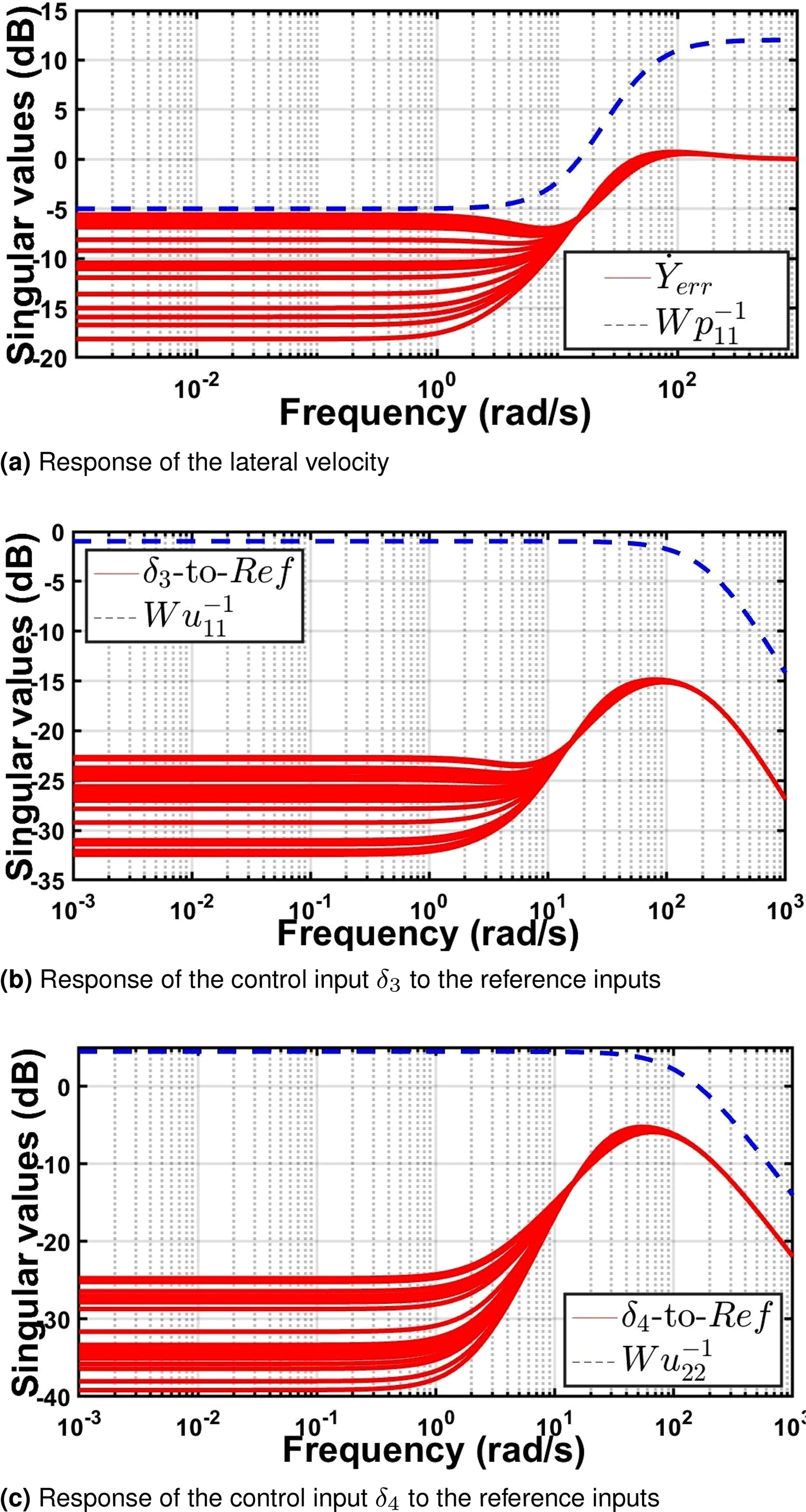
CLS frequency response. (a) Response of the lateral velocity, (b) response of the control input
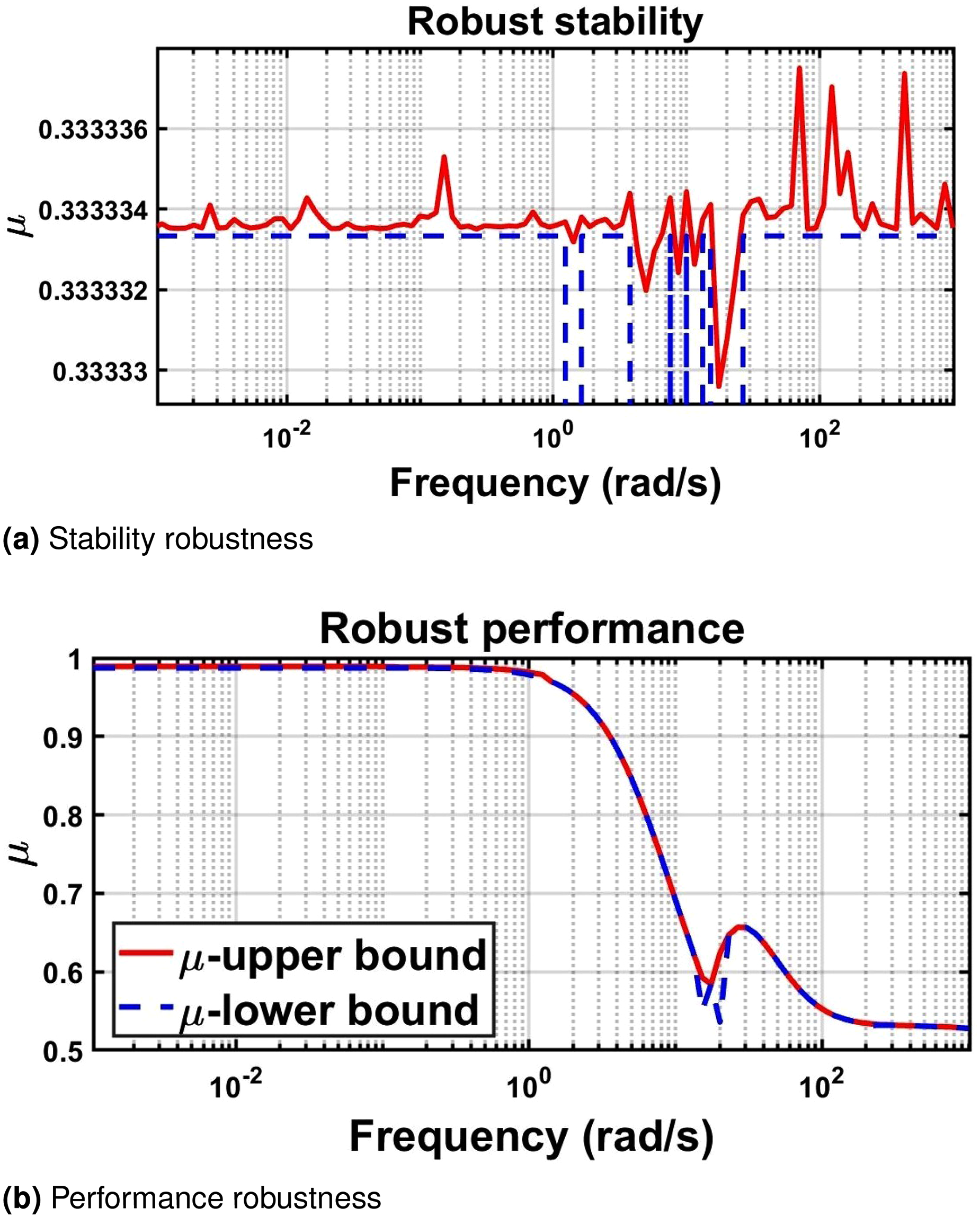
Robustness of the front steering CLS. (a) Stability robustness and (b) performance robustness.
Evaluation and simulation results
A nonlinear model for an
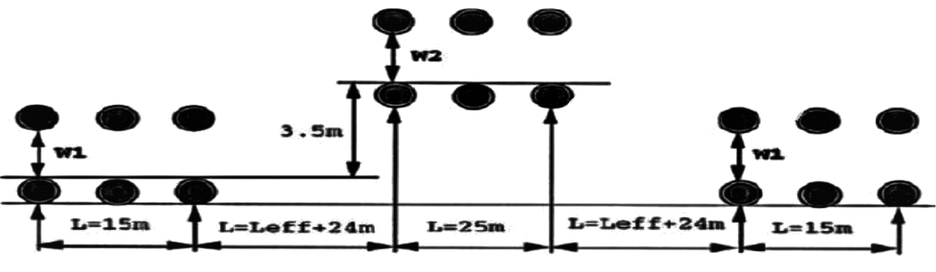
The controllers are compared and evaluated by performing the NATO DLC as in Figure 10 at various speeds (
Low-speed evaluation using DLC maneuver
In this section, the controllers will be evaluated at low speed (
At friction coefficient = 0.85 and forward speed = 40 km/h
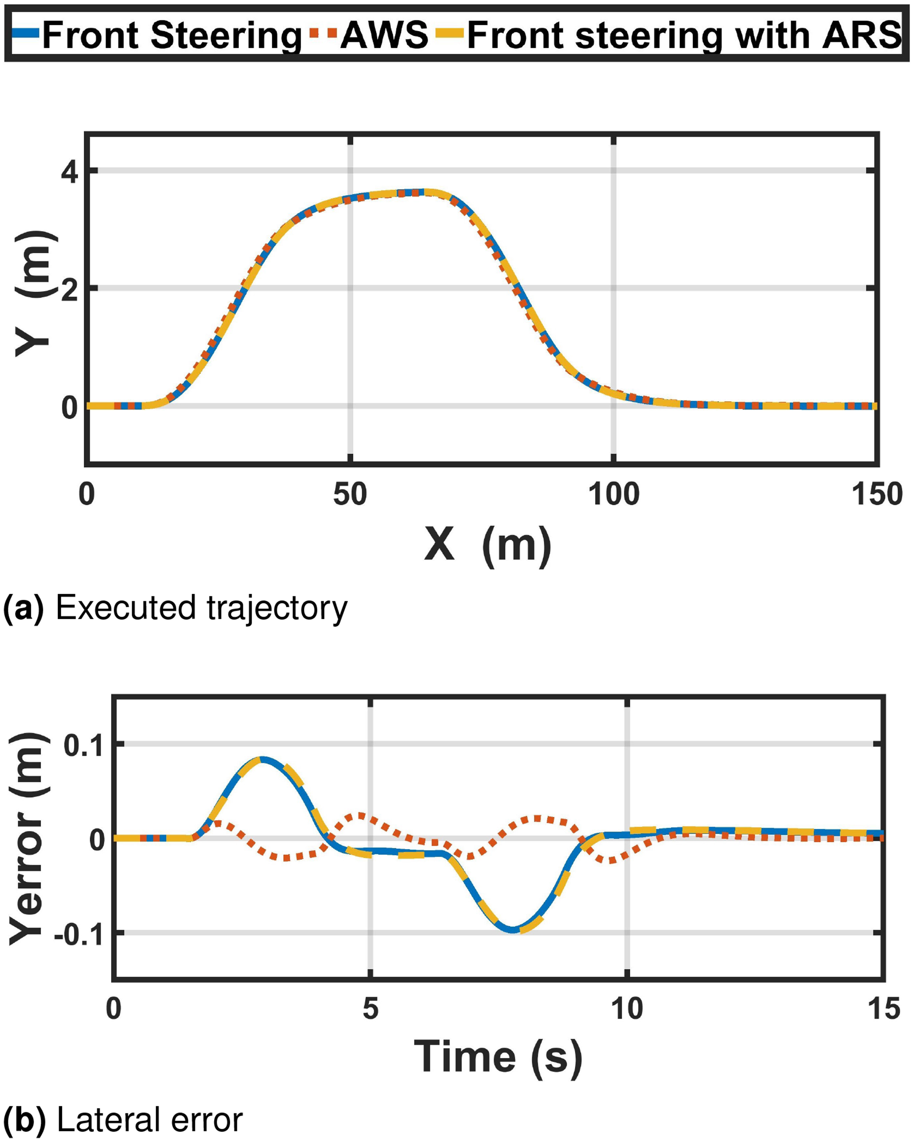
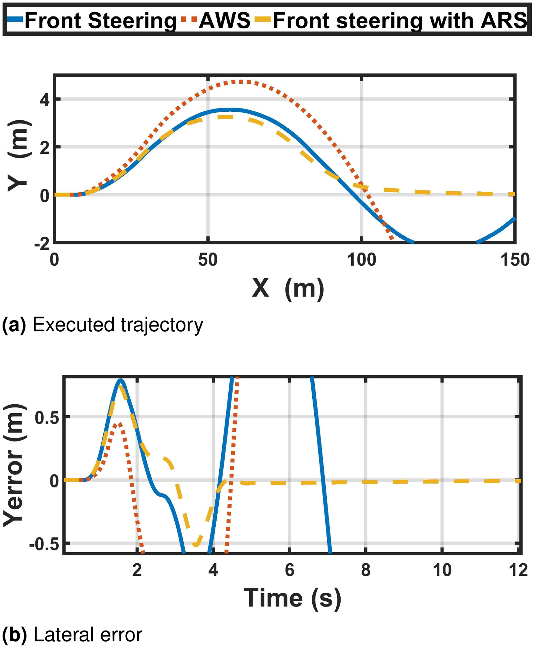
Figure 11(a) and (b) shows the vehicle trajectory and the corresponding lateral error when driving at speed
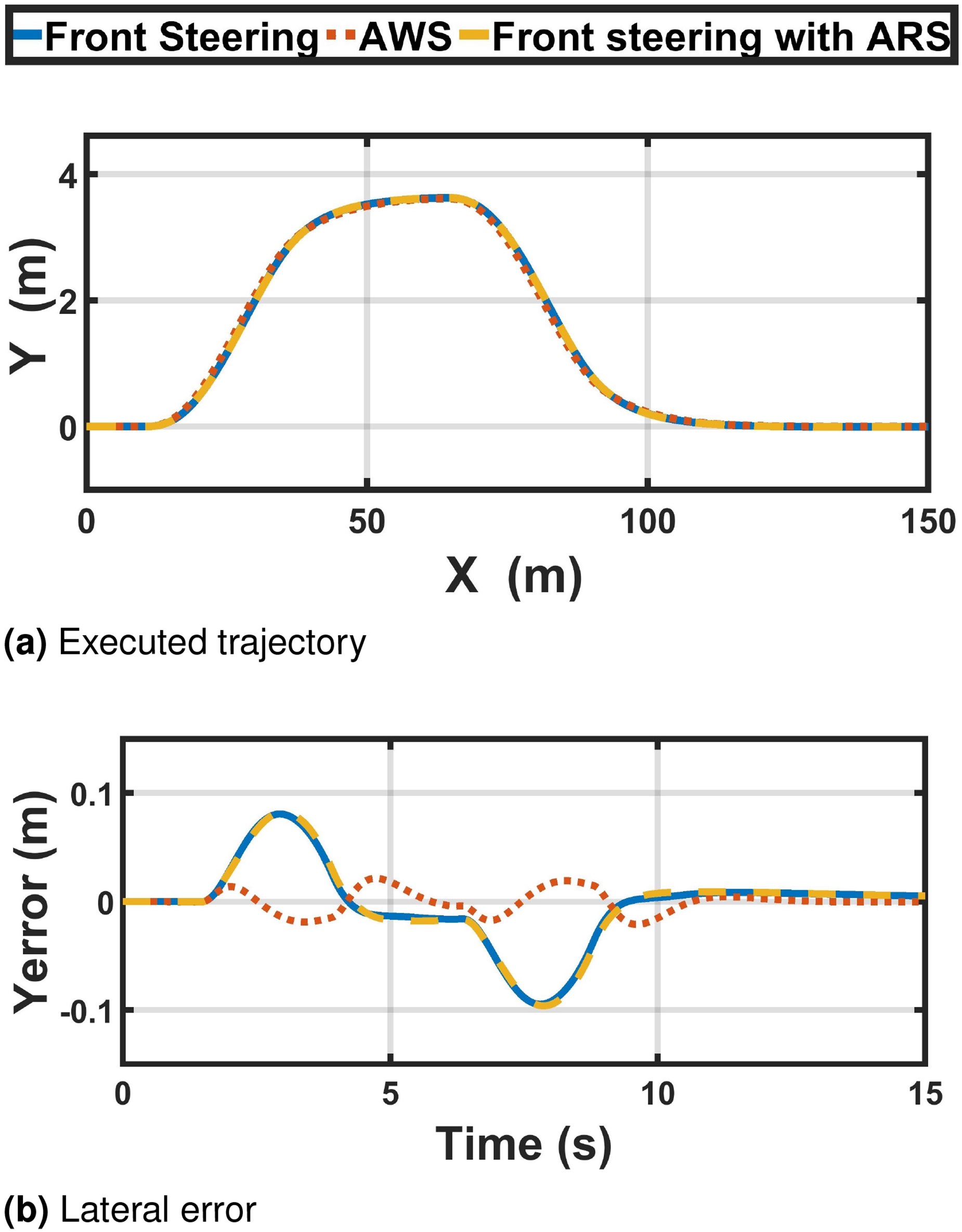
DLC manoeuver (CoF = 0.85, speed = 40 km/h). (a) Executed trajectory and (b) lateral error.
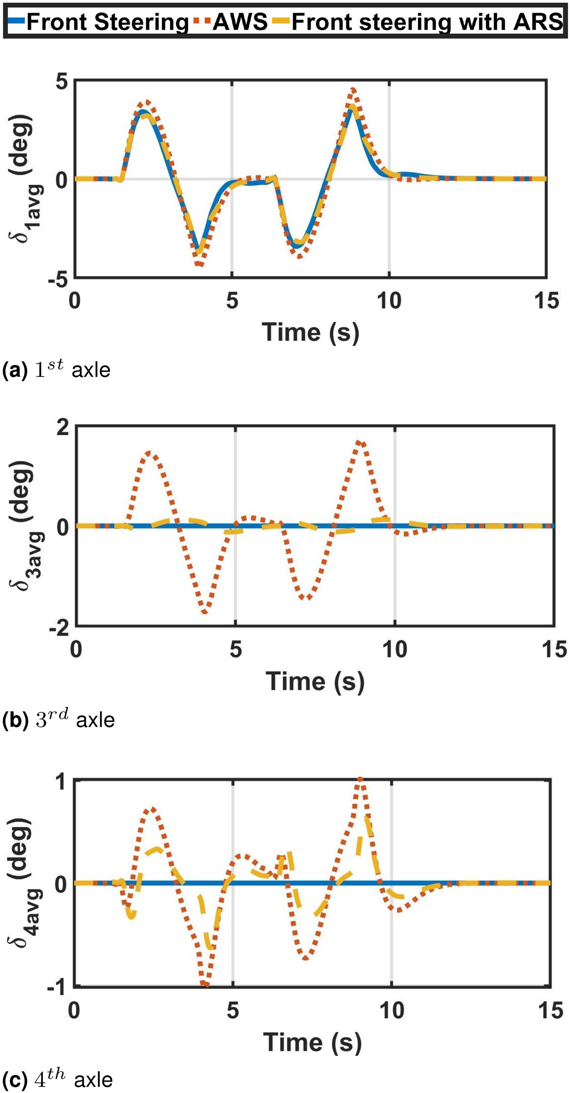
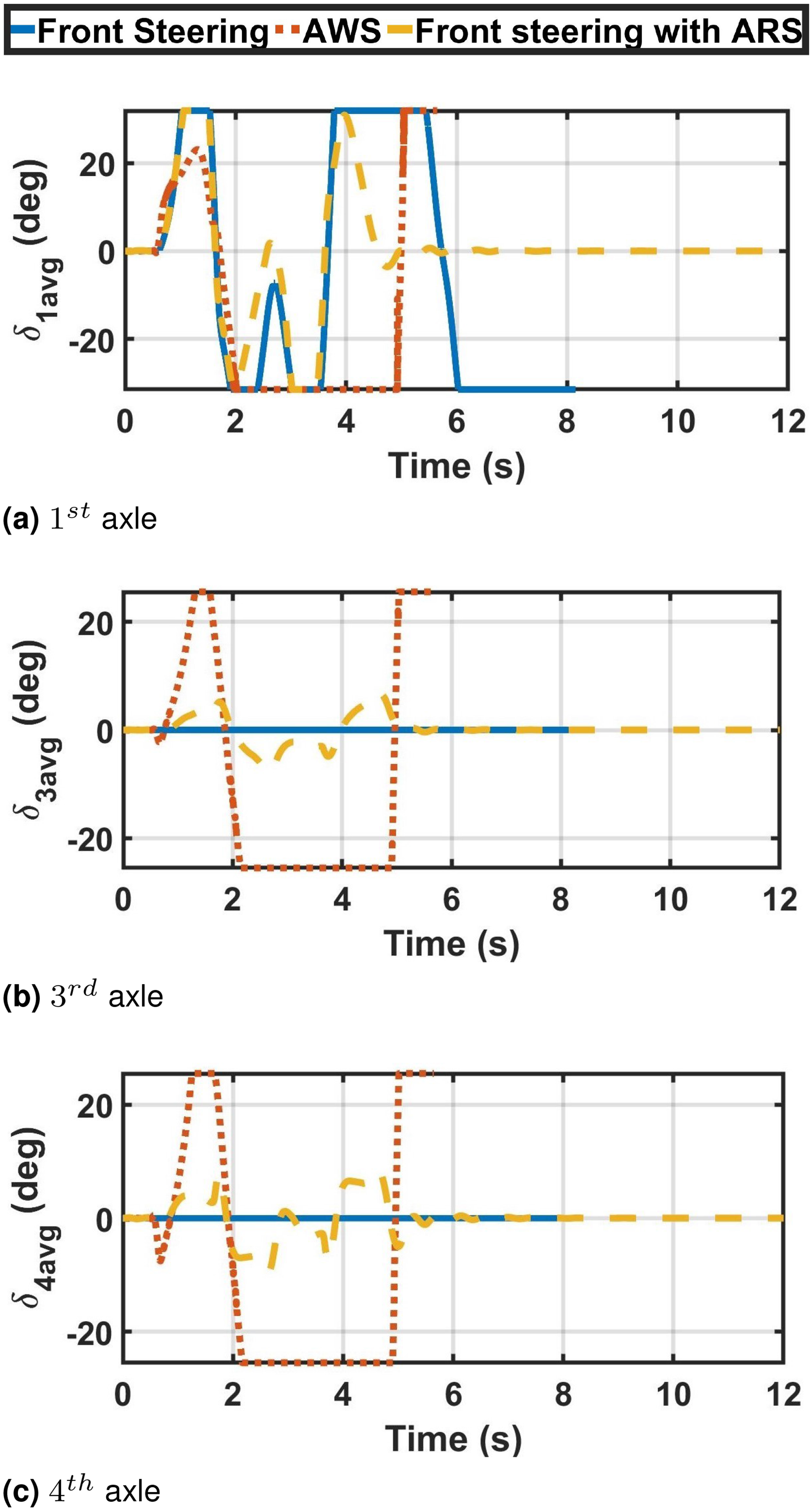
Axles’ average steering angle (CoF = 0.85, speed = 40 km/h). (a) 1
st
axle, (b)
The first, third, and fourth axle’ average steering angles are illustrated in figure 12(a), (b), and (c), respectively. It is noticed that there is no huge difference between front steering-based controllers (front steering and front-ARS), while the front steering angle of the AWS is slightly higher. In contrast, there is a big difference in the
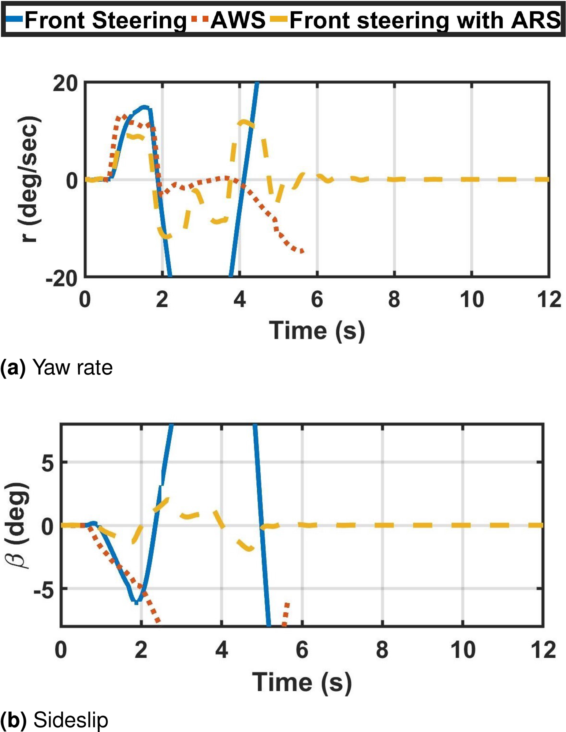
The yaw rate response is shown in Figure 13(a), where there is almost no difference between the three cases. Figure 13(b) presents the vehicle sideslip angle for each case, it is notable that for almost the same yaw rate, the integrated front-ARS generates the least sideslip. Meanwhile, the AWS reaches the same sideslip as the front steering controller. However, due to the added weight for tracking the yaw angle at low frequencies, AWS generates a uniform sideslip that has the same shape and phase as the yaw rate signal.
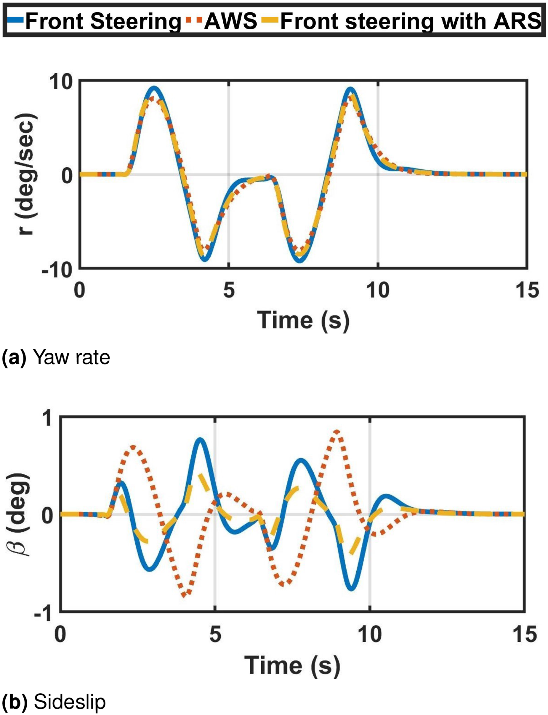
Vehicle’s dynamic response (CoF = 0.85, speed = 40 km/h). (a) Yaw rate and (b) sideslip.
At friction coefficient=0.5 and forward velocity=40 km/h
The vehicle trajectory when driving on a surface with friction coefficient
DLC maneuver (CoF = 0.5, speed = 40 km/h). (a) Executed trajectory and (b) lateral error.
High-speed evaluation using DLC maneuver
In this section, all cases are evaluated at the maximum speed of each test on roads with various CoF (
At friction coefficient = 0.85 and forward velocity = 100 km/h
The vehicle trajectory is presented in Figure 15(a) when performing the maneuver with speed
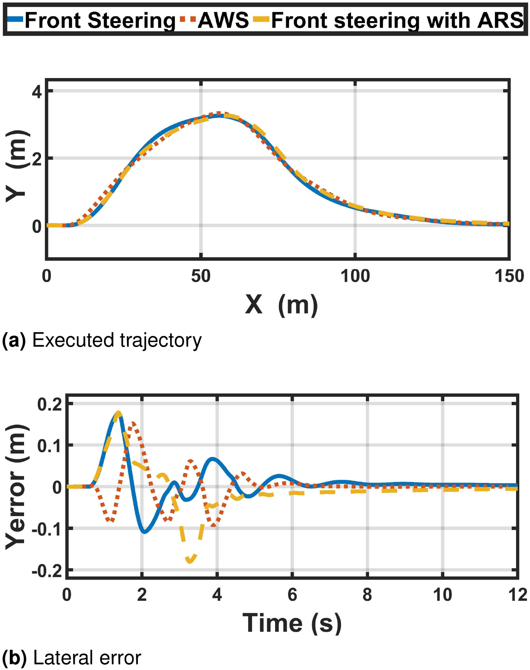
DLC maneuver (CoF = 0.85, speed = 100 km/h). (a) Executed trajectory and (b) lateral error.
The front steering controller resulting in the highest average front steering angle among all cases as shown in Figure 16(a). The front-ARS results in a higher
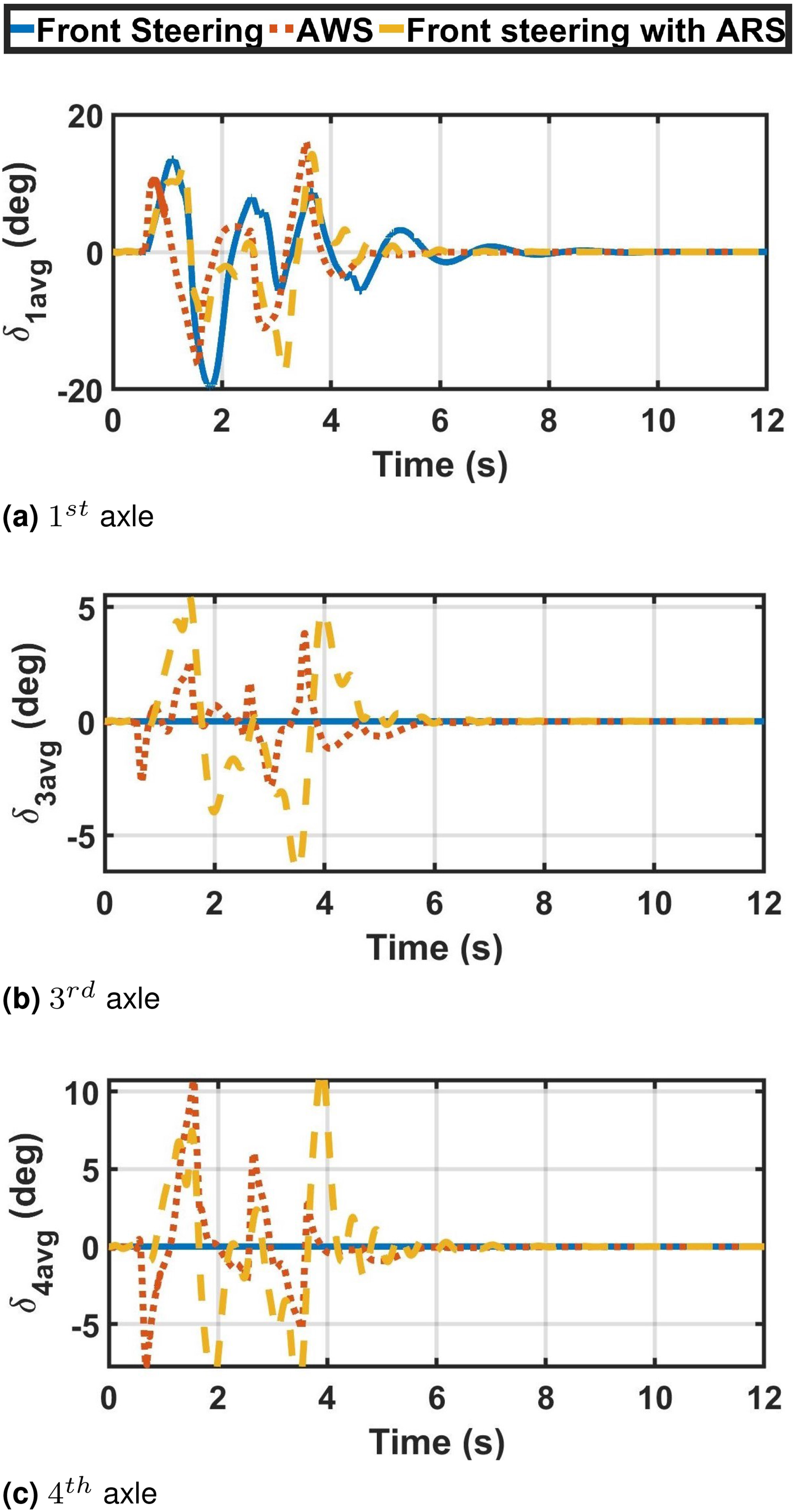
Axles’ average steering angle (CoF = 0.85, speed = 100 km/h). (a) 1
st
axle, (b)
The dynamic response of all cases is illustrated in Figure 17. The less reduction in the longitudinal velocity is achieved by the integrated front-ARS, followed by the AWS, then the front steering that produces the highest reduction as presented in Figure 17(a). Meanwhile, the front-ARS results in the least yaw rate because of the very low sideslip as observed in Figure 17(b) and (c), respectively. In addition, the AWS and the front-ARS stabilize almost at the same time and faster than the standalone front steering.
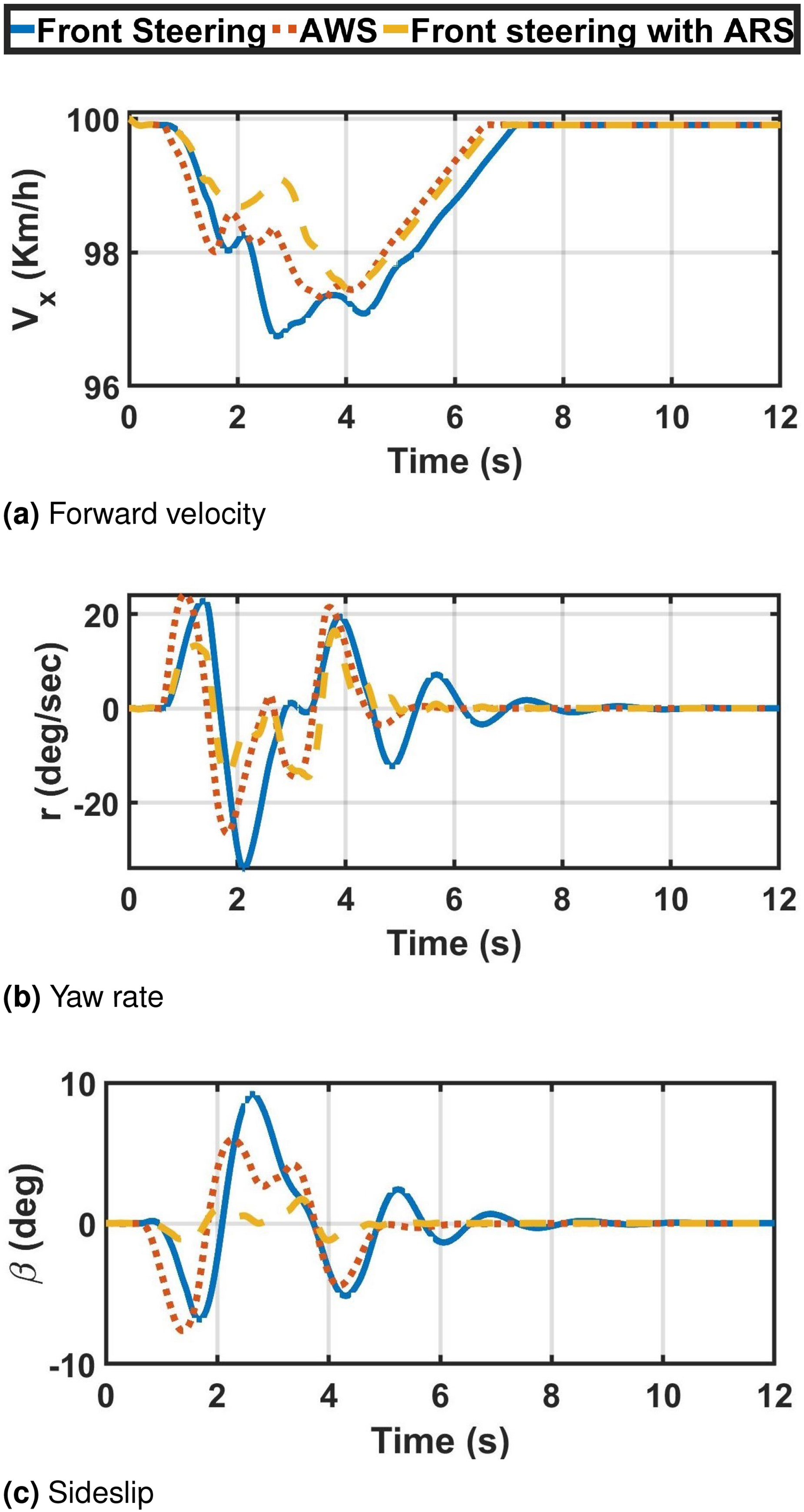
Vehicle’s dynamic response (CoF = 0.85, speed = 100 km/h). (a) Forward velocity, (b) yaw rate, and (c) sideslip.
At friction coefficient = 0.5 and forward velocity = 100 km/h
In this section, the controllers are evaluated at high speed (
It is shown in Figure 18(a) that all other cases fail to stabilize the vehicle and finish the maneuver except for the integrated front-ARS controllers, which pass the maneuver despite the generated high lateral error, as presented in Figure 18(b). As can be observed in Figure 19(a), there is a saturation in the first
DLC maneuver (CoF = 0.5, speed = 100 km/h). (a) Executed trajectory and (b) lateral error.
Axles’ average steering angle (CoF = 0.5, speed = 100 km/h). (a) 1
st
axle, (b)
The yaw rate and sideslip responses show the effectiveness of the ARS in limiting the yaw rate and sideslip as shown in Figure 20(a) and (b), respectively and regain the vehicle stability.
Vehicle’s dynamic response (CoF = 0.5, speed = 100 km/h). (a) Yaw rate and (b) sideslip.
Conclusions
In this paper, three H∞ controllers are developed to control the vehicle path. The first is a path-following controller that utilizes the steering of the front axles only. The second is also a path-following controller, which exploits the steering of all axles. The third controller integrates the front steering path-following controller with a lateral stability ARS controller.
Frequency analysis is conducted for the closed-loop control systems. The analysis shows that including the steering of the rear axles enhances the path-following performance by tightening the constraints on the lateral position tracking, heading angle tracking, and control inputs responses. Furthermore, the frequency response analysis of the developed ARS-stability controller shows the effectiveness of the rear axles in constraining the vehicle sideslip with minimum utilization of the rear axles.
The three cases were compared and evaluated by performing series of DLC maneuvers. The results show that AWS system generates the minimum lateral error. In addition, penalizing the heading angle tracking error and its integration adds the benefits of fast stabilization at a relatively high-speed maneuver. It is also observed that the AWS generates a sideslip with the same phase as the yaw rate at low speeds, which increases the vehicle maneuverability, and a counter phase at high speed, which reduces the vehicle sideslip and enhances the stability. On the other hand, the ARS generates a counter-phase sideslip in all driving conditions resulted in a reduction of the sideslip to enhance stability. This behavior shows the superiority of ARS in performing maneuvers at the limited-handling conditions, in which the front steering and AWS path-following controllers failed.
It is more effective to design a path-following controller utilizing all-axles steering than including an ARS to the front steering at low speeds. In contrast, it is more beneficial to integrate a lateral stability-ARS with a front steering path-following controller at high speeds. Therefore, it is recommended to design a parametric variable or a switching controller that alters the objective of steering the rear axles considering the road friction coefficient and vehicle‘s driving speed.
Finally, combat vehicles are required to be operated in different driving conditions, including on-roads and off-roads. Therefore, the off-road analysis will be performed in a future study.
Footnotes
Declaration of Conflicting Interests
The author(s) declared no potential conflicts of interest with respect to the research, authorship, and/or publication of this article.
Funding
The author(s) received no financial support for the research, authorship, and/or publication of this article.