
Abstract
The piston compression ring's primary function is to seal the combustion chamber, thus mitigating gas leakage to the crankcase and avoiding loss of pressure loading. As a result, the ring is meant to conform closely to the cylinder surface which promotes increased friction. The compression ring is subjected to combustion pressure loading, ring tension, varying inertial force and friction. It is a slender ring of low mass, thus undergoes complex elastodynamic behaviour, when subjected to a multitude of forces. These motions occur in the ring's radial in-plane and axial out-of-plane dynamics, which comprise flutter, ring axial jump, compression-extension, ring twist and rotational drag. An implication of these motions can be loss of sealing, gas blow-by, loss of power and lubricant degradation/oil loss, to name but a few. Consequently, understanding and accurately predicting ring dynamic behaviour under transient conditions is an important step in any subsequent modelling for evaluation of cylinder system efficiency. There have been a plethora of investigations for ring dynamics, often decoupling the ring behaviour in its in-plane and out-of-plane motions. This approach disregards any transfer of dynamic energy from one degree of freedom to another which is only applicable to rectangular ring cross-sections. Alternatively, there are computationally intensive approaches such as finite element analysis which are not conducive for inclusion in any subsequent system level engine modelling where ring response alters in an instantaneous manner. This would require embedded finite element analysis within a transient analysis. This paper presents a finite difference numerical analysis for coupled in-plane and out-of-plane motions of compression rings with practical cross-sectional geometries, which are mostly not rectangular. The formulated method can be integrated into a system level transient cyclic analysis of ring-bore contact. The presented approach takes into account the energy transfer between different degrees of freedom. The predictions are validated against precise non-contact measurements of ring elastodynamic behaviour under amplitude-frequency sweeps. This approach has not hitherto been reported in literature and constitutes the main contribution of the paper.
Introduction
Fuel efficiency and increased output power-to-weight ratio are the key drivers in powertrain development. These requirements are coupled with increasingly stringent emission legislations and directives. To fulfil these demands, the common desired attributes are reduced powertrain losses, light-weight and compact constructions.
The piston compression ring can be responsible for a disproportionate 3–5% of the total engine losses, given its small size. 1 Understanding the ring's dynamic response is a prerequisite for accurately determining the frictional losses associated with it. These losses are determined through a tribological study, which requires a number of key parameters. These include ring geometry and topography,2,3 ring tension and gas loading,4,5 bore shape 6 and contact kinematics. The dynamic behaviour of the ring determines its loading, kinematics and contact geometry. Subsequently, a tribological study of the conjunction provides the generated contact pressures and load carrying capacity, as well as friction, which in turn affects the ring dynamic response.2–10 Therefore, a combined dynamics and tribological study of the problem is required.
The compression ring performs a number of functions for the effective operation of the internal combustion engine. Primarily, the compression ring acts as a seal between the crankcase and the combustion chamber. The engine cycle prescribes the applied forces to the piston compression ring. These include combustion gas pressure, contact friction between the ring and the liner, ring tension, and inertial forces. These forces excite a plethora of ring modal responses, which may adversely compromise its functionality. These include ring flutter and jump, twist and rotation.8–10 The elastodynamics of the compression ring is also a prerequisite for the prediction of these phenomena which cause blow-by, loss of sealing, thus power loss, as well as lubricant degradation. Therefore, the main emphasis of this paper is to develop a verified and representative ring elastodynamic model.
Tian et al. 11 demonstrated that static twist affected the ring-groove contact characteristics, stability and blow-by. Tian 10 considered the ring twist and gas flow model without transient ring dynamics. The study demonstrated the importance of ring flutter on gas flow and oil transport. Baelden and Tian 12 utilised a curved beam finite element approach to model the compression ring for ring-bore conformability analysis, 13 necessitating consideration of ring dynamics. It was noted that the inclusion of ring dynamics improves the noted differences between predictions 13 and measurements. 14 Baker et al.8,9 showed progressive improvements in numerical predictions of friction by validating them against the experimentally obtained measurements of lubrication film thickness reported by Takiguchi et al. 15 Dowson et al. 16 presented a one-dimensional elastohydrodynamic analysis of the ring bore along the rings' contact face width. Mishra et al. 13 took into account combined elastodynamic and asperity interactions based on an approach demonstrated by Hu et al. 17 The analysis utilises the 2D Reynolds equation, lubricant rheological state equations and the Greenwood and Tripp's method.18,19
Elastodynamics of the piston compression ring was also modelled by Ejakov and Schock 20 to describe the effect of ring twist in internal combustion engines. The model was based on a discretisation method, using a number of perfectly elastic Timoshenko beam elements with assumed coincidence of the ring's shear centre and its cross-sectional centroid. Straight beam elements were used with uniform cross-sections between successive computational nodes. The straight beam elements were concatenated to approximate the structure of an incomplete circular ring. Assuming coincident cross-sectional centroid and the shear centre enables solution of the in-plane and out-of-plane ring dynamics becomes uncoupled. With this assumption, no energy can be transferred from a degree of freedom to another. This assumption is reasonably valid for symmetric cross-sections such as that of a rectangular ring. This approach can be used with a number of alternative beam element formulations, for example in the dynamic stiffness matrix method (DSMM) to model crankshaft flexibility as detailed in Okamura et al. 21 and Rahnejat 22 This method solves the governing differential equations of motion by embedding the mass and stiffness terms into a frequency-dependent matrix. This method is also based on the Eulerian beam theory, with the beam cross-section remaining perpendicular to the axis of bending. The approach is valid for structures with high length-to-width ratio. Okamura et al. 21 assumed that the shear centre and centre of area of the cross section remain coincident, typical of crankshaft systems. This approach is also based on the uncoupled dynamics, similar to that presented in Ejakov and Schock. 20 A curved beam finite element approach has been utilised to represent the elasticity of the ring by Baelden and Tian. 12
Analytical solutions also exist for incomplete rings by Lang 23 for the in-plane ring motion and by Ojalvo23,24 for the ring out-of-plane motion. These solutions consider uncoupled in-plane and out-of-plane motions for a symmetric ring cross-section, which is not valid for real compression rings. The equations of motion for in-plane and out-of-plane dynamics of the piston compression ring were also solved by Baker et al.8,25,26 for the evaluation of ring friction and power loss within internal combustion engines. The method of solution considered four degrees of freedom and required the cross-section to be modelled as an equivalent rectangle, also neglecting the coupling effect between the in-plane and out-of-plane motions.
Banerjee 27 derived an equivalent formulation for the coupled bending-torsion motion of an aircraft wing, where the shear and mass centres do not coincide. Analytical expressions for the coupled solution of axially loaded beam elements with non-coincident shear and mass centres were also presented by Banerjee et al. 28 The method was used to solve the frequency response of axially loaded helicopter turbine and propeller blades, as well as space frames. The paper demonstrated the importance of coupling of degrees of freedom on the frequency response of the system for a number of applications. Rao and Carnegie 29 analysed the fully coupled solutions for aircraft turbine blades. The governing Eulerian beam equations were directly solved by Ritz-Galerkin method. The paper demonstrated the importance of coupling upon the frequency response of aircraft turbine blading.
The fully coupled solution, applicable for complex beam cross-sections, allows energy to transfer between the structural modes such as in bending and torsion. The transfer of energy between the in-plane and out-of-plane motions of a compression ring is important for the analysis of a number of different phenomena during the engine cycle. These include the lubricant squeeze film effect at top-dead centre reversals, as well as ring flutter, twist, rotation and jump. Therefore, from a practical viewpoint prediction of these motions are essential in palliating power loss through mitigation of friction as well as loss of ring sealing. This paper presents such a methodology. The differential equations of motion are discretized using a finite difference method and integrated in the time domain using 12th order Runge–Kutta–Nyström integration method. The predictions are validated against experimental measurements of ring elastodynamic behaviour, when subjected to excitation. The numerical model combined with the experimental analysis is intended to improve the accuracy of the numerical tribological models that are used in any subsequent analysis to evaluate frictional power losses from piston ring – liner system. Previous studies such as Tian et al. 11 and Baker et al. 30 have shown the significance of the ring elastodynamics on the prediction of the frictional losses in IC engines. Significance of the current analysis is in obtaining an efficient numerical representation of the top compression ring elastodynamic behaviour for use in subsequent tribological evaluation.
Numerical model
Figure 1 shows an Eulerian beam with four-degrees of freedom, comprising bending in the planes xz and xy, axial extension/compression as well as torsional degrees of freedom. x represents the local circumferential direction at any position along the ring. z is the out-of-plane and y are the in-plane directions.
The Eulerian beam element with corresponding coordinate system.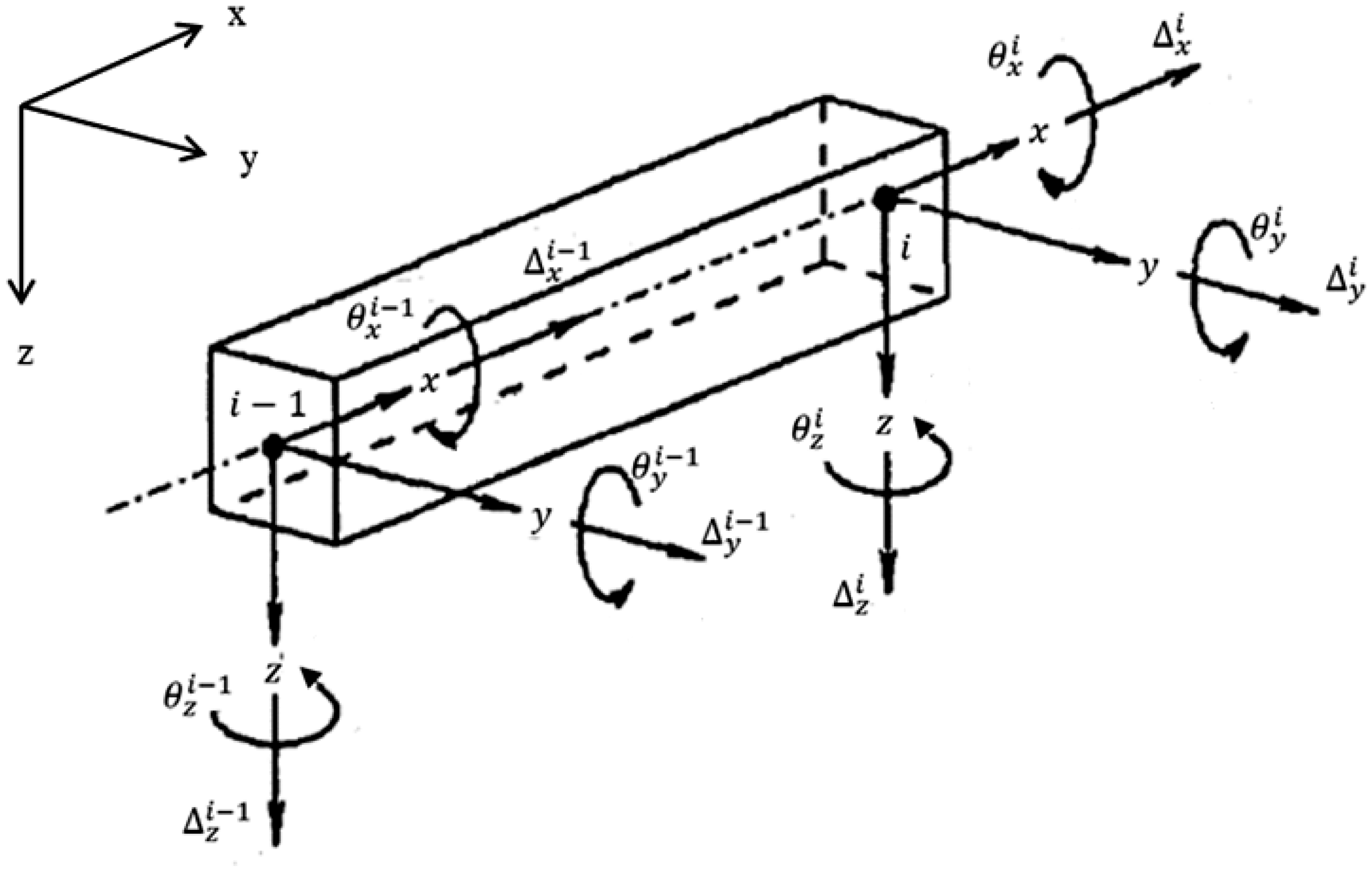
The coupled governing differential equations of motion for the beam are
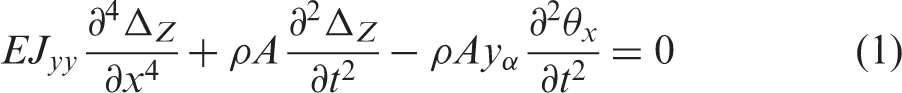
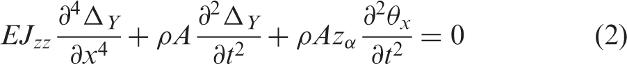
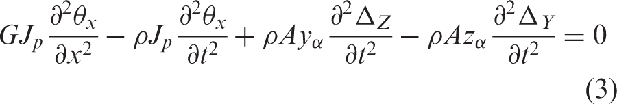
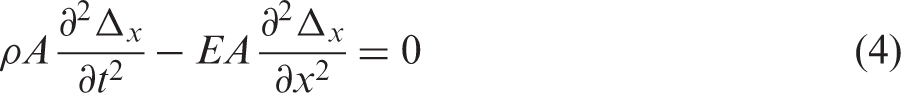
The co-ordinate coupling terms are provided by the constants
The coupled system of the differential equations (1) to (4) represents the continuum of beam's elastic deformation. These governing differential equations are discretised using central finite differences in a number of grid points along the ring. The ring dynamic response under the applied load is then obtained through solution of these equations for any given boundary conditions. Since the purpose of the current analysis is to demonstrate the coupling of ring's in-plane and out-of-plane dynamics, appropriate boundary conditions need to be used in the solution of equations (1) to (4). Furthermore, it is essential to obtain validation for the proposed methodology. For this purpose, an experimental set up is made (see section ‘Experimental Investigation’). Therefore, the boundary conditions used for the solution of equations (1) to (4) correspond to the boundary conditions of the experimental set up, which is for a clamped incomplete compression ring, shaken by an exciter with a prescribed amplitude-frequency sweep. Therefore, clamped boundary condition is prescribed at one of the incomplete ring ends in the numerical model. The response of the incomplete ring is measured from the other end point of the incomplete ring-gap (Figure 2).
Schematic of the numerical model and experimental setup.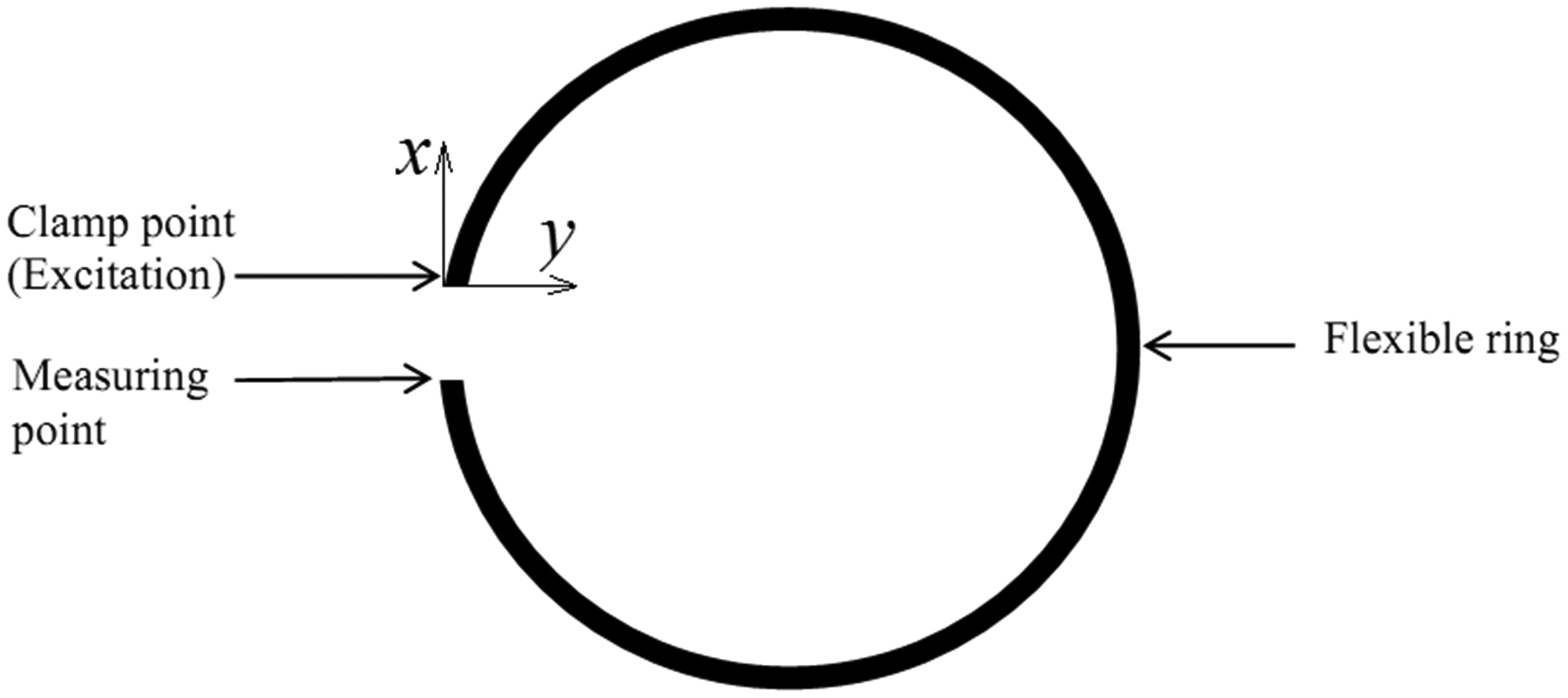
Excitation is provided in terms of a specified displacement and velocity, closely replicating the exciter-applied motion. The displacement
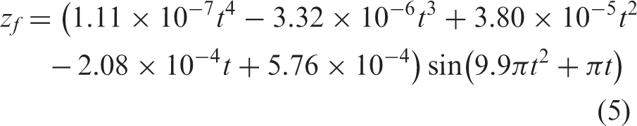
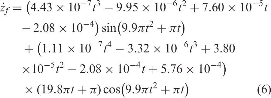
These functions represent the experimentally applied excitation in terms of the amplitude and frequency obtained through curve fitting.
Finite element analysis
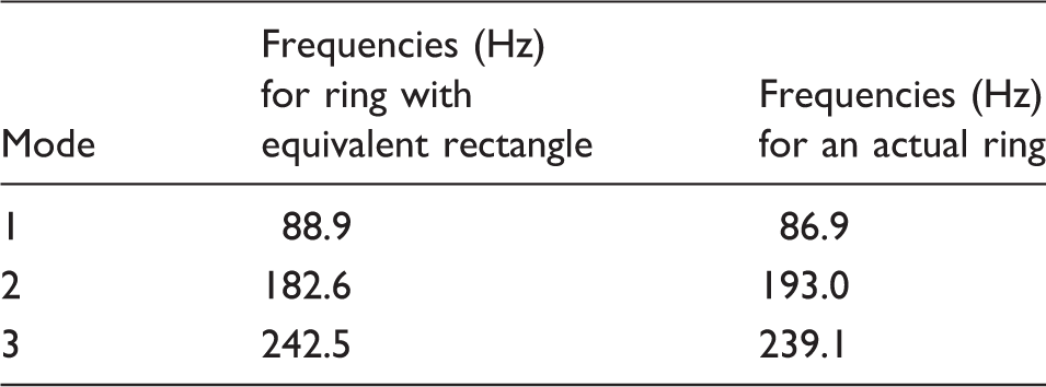
Frequency comparison of an equivalent rectangular cross-section with an actual ring of non-rectangular cross-section (obtained through FEA analysis).
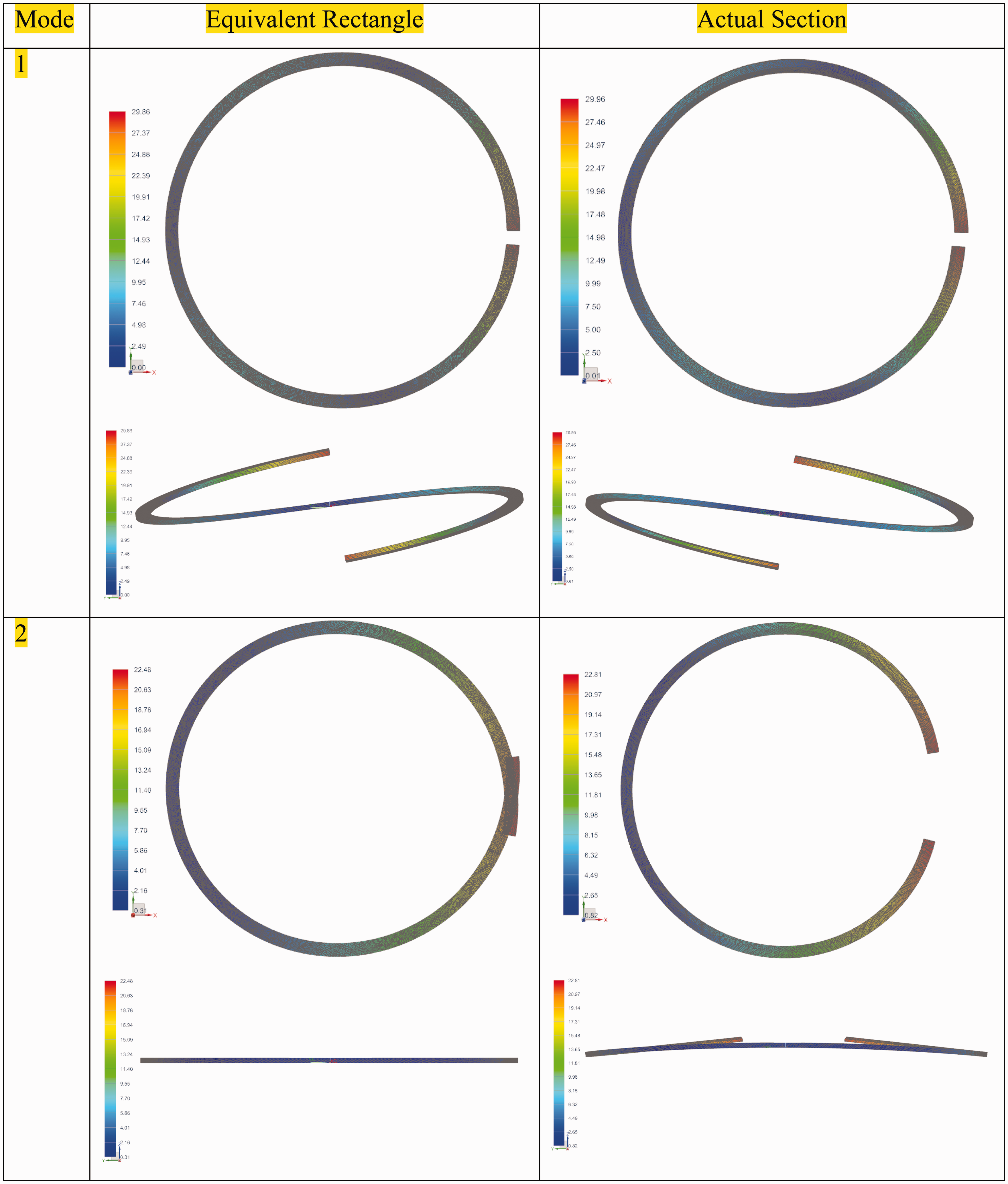
Comparison of mode shapes between equivalent rectangular and actual cross-section rings.
Experimental investigation
Figure 4 shows the experimental rig, comprising a clamped piston compression ring, mounted upon an LDA shaker (exciter). It is essential to use a precision method of measurement for the ring response as mounting of any transducer(s) onto the thin ring of low mass would significantly affect its modal response. Therefore, three laser Doppler vibrometers (LDV) are positioned in appropriate locations to monitor the applied amplitudes of excitation (in the radial in-plane and axial out-of-plane directions), as well as the ring response. Note that the applied shaker excitation is transmitted to the clamped ring in both radial and axial directions. Therefore, two of the vibrometers (LDV 1 and LDV 3) are used to accurately measure the applied in-plane and out-of-plane excitations. Another LDV (i.e. LDV 2) is used to measure the out-of-plane response of the ring at its free end gap.
The experimental setup. (a) Overview of the rig. (b) Zoomed view of the ring and clamping arrangement.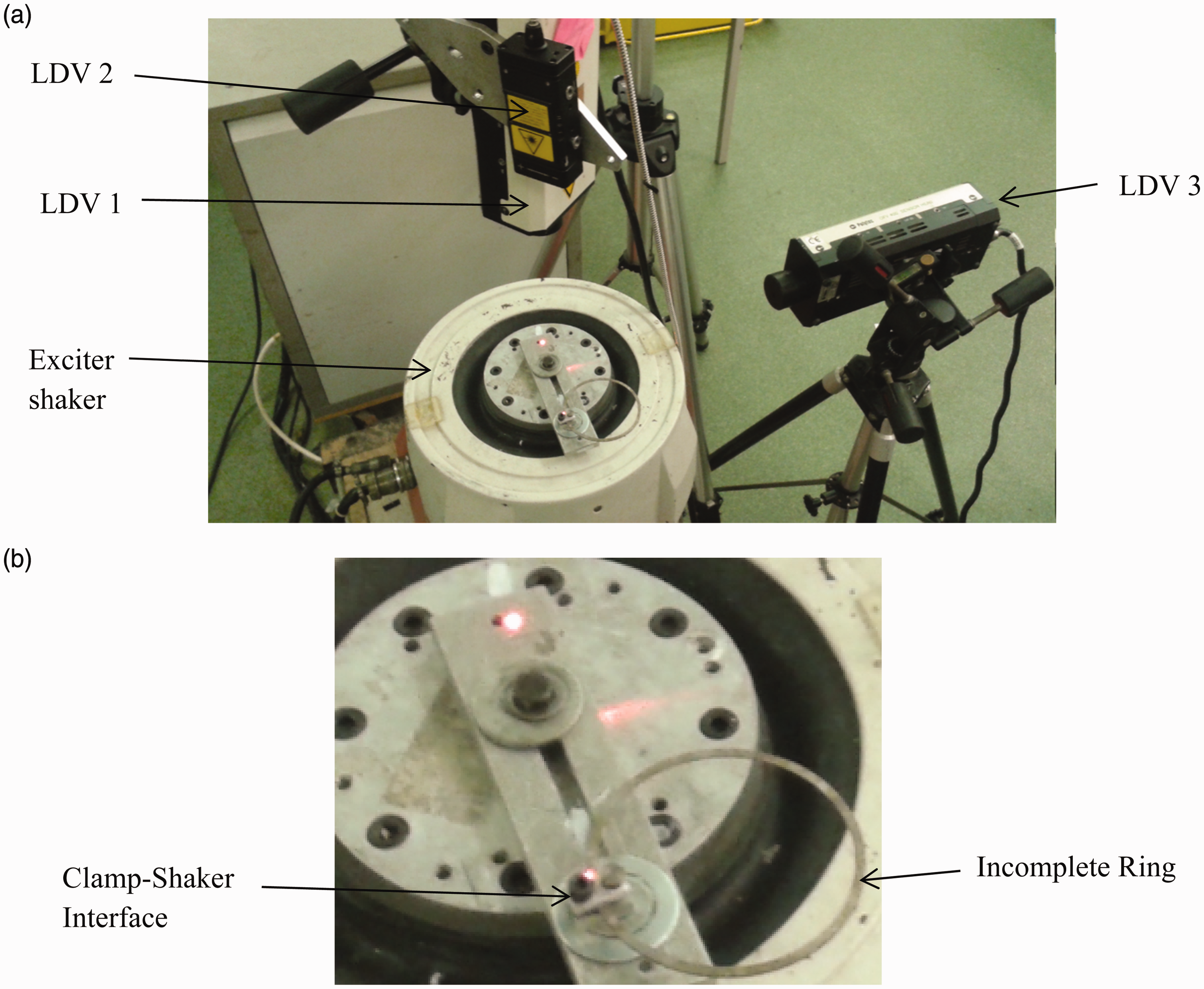
Instrumentation.
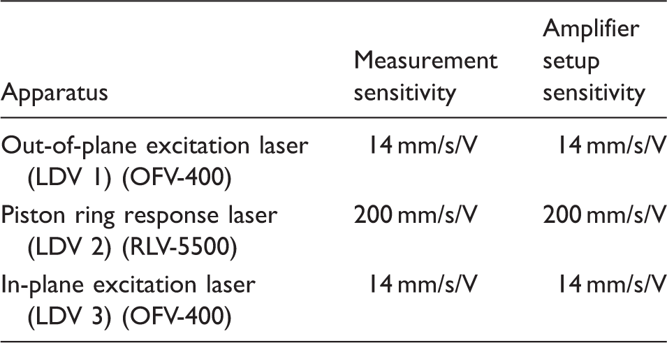
LDV: laser Doppler vibrometers.
A sampling rate of 8000 Hz was employed, when the piston compression ring was excited using a linear sweep function from 1 Hz to 100 Hz for a duration of 10 s.
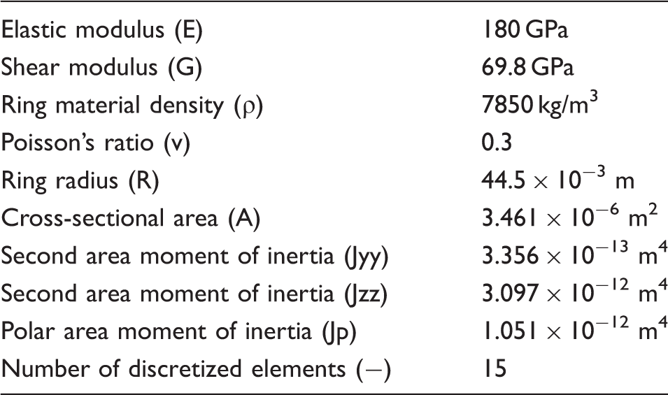
Figure 5 and Table 3 provide the geometric and material properties of the compression ring used.
Cross-section of the ring. Ring data.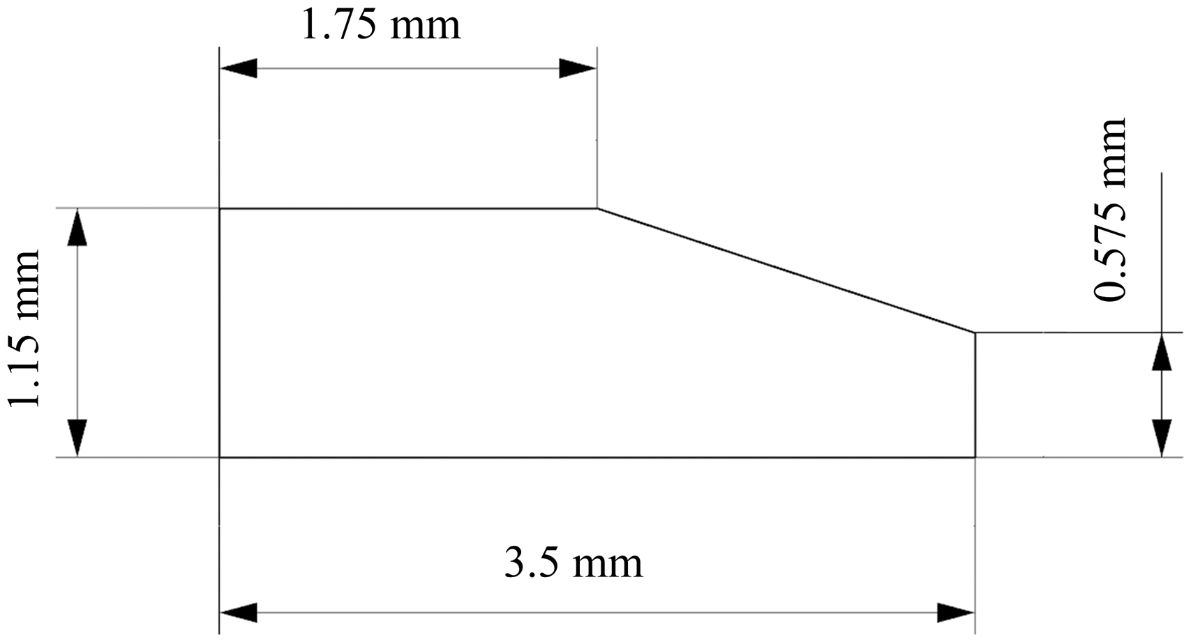
Results and discussions
FEA comparison of the frequencies from actual cross section and the developed Euler ring model.
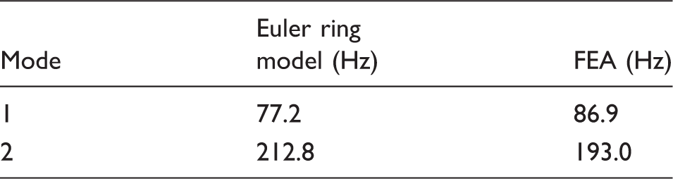
FEA: finite element analysis.
The comparison shows percentage differences of 11% (under-estimation) for mode 1 and 9% (over-estimation) for mode 2 by the developed Eulerian method and FEA. This is quite reasonable, particularly that an FEA model requires re-meshing if included in a transient analysis of ring-bore contact during an engine cycle due to changes in boundary and operating conditions. This renders any subsequent tribological analysis impractical in computational space-time requirements, which is not the case with the developed Eulerian method which can be incorporated in transient tribological method mathematically as an integrated solution.
The next step is model validation against experimental measurements. For this purpose, a series of frequency sweep excitations in the range 10 Hz–100 Hz were undertaken, each for a period of 10 s. Figure 6 shows the displacement time history of the experimental excitation over two such sweeps. This approach is replicated in the numerical model (noted in section ‘Numerical Model’).
Time history of applied excitation.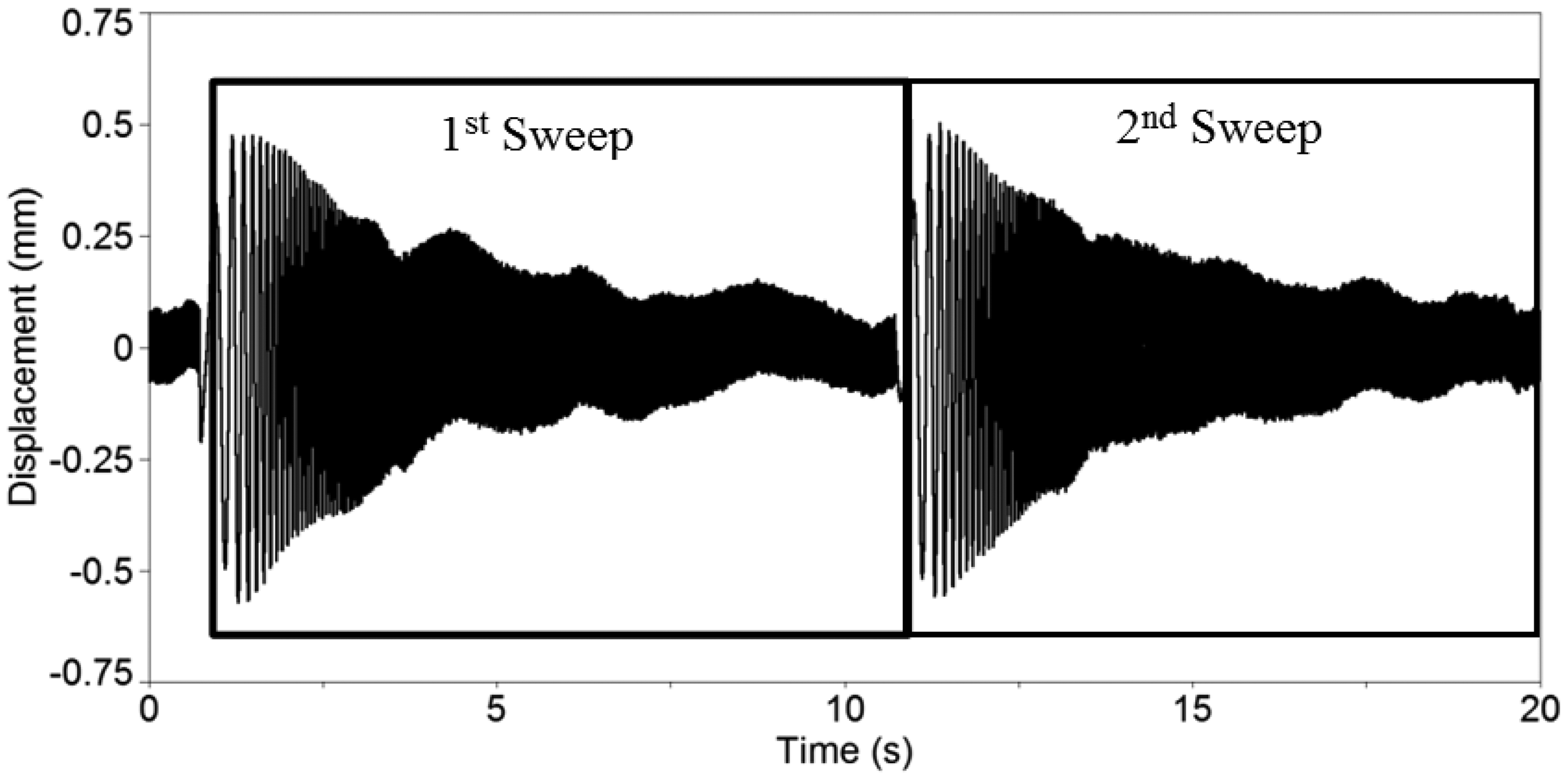
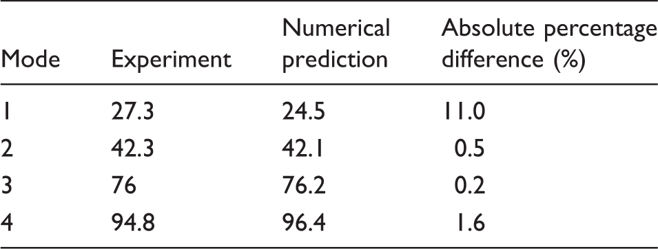
Figure 7 shows the wavelet of the out-of-plane ring response as measured by the LDV2 at the ring's free end gap. The first excitation sweep is also highlighted in the figure. The first four response frequencies are highlighted in the figure. The first frequency occurs at 27.3 Hz with some modulations (i.e. 20.1 Hz and 34.0 Hz). This first response frequency is the dominant response with a slow transient decay. The second response frequency occurs at 42.3 Hz with a lower amplitude than the first frequency. The third and fourth responses occur at 76 Hz and 94.8 Hz, respectively. The first two responses act predominantly in the out-of-plane (axial) direction of the ring, while the third and fourth response components occur predominantly in the radial in-plane direction.
Measured out-of-plane response of the ring's free end.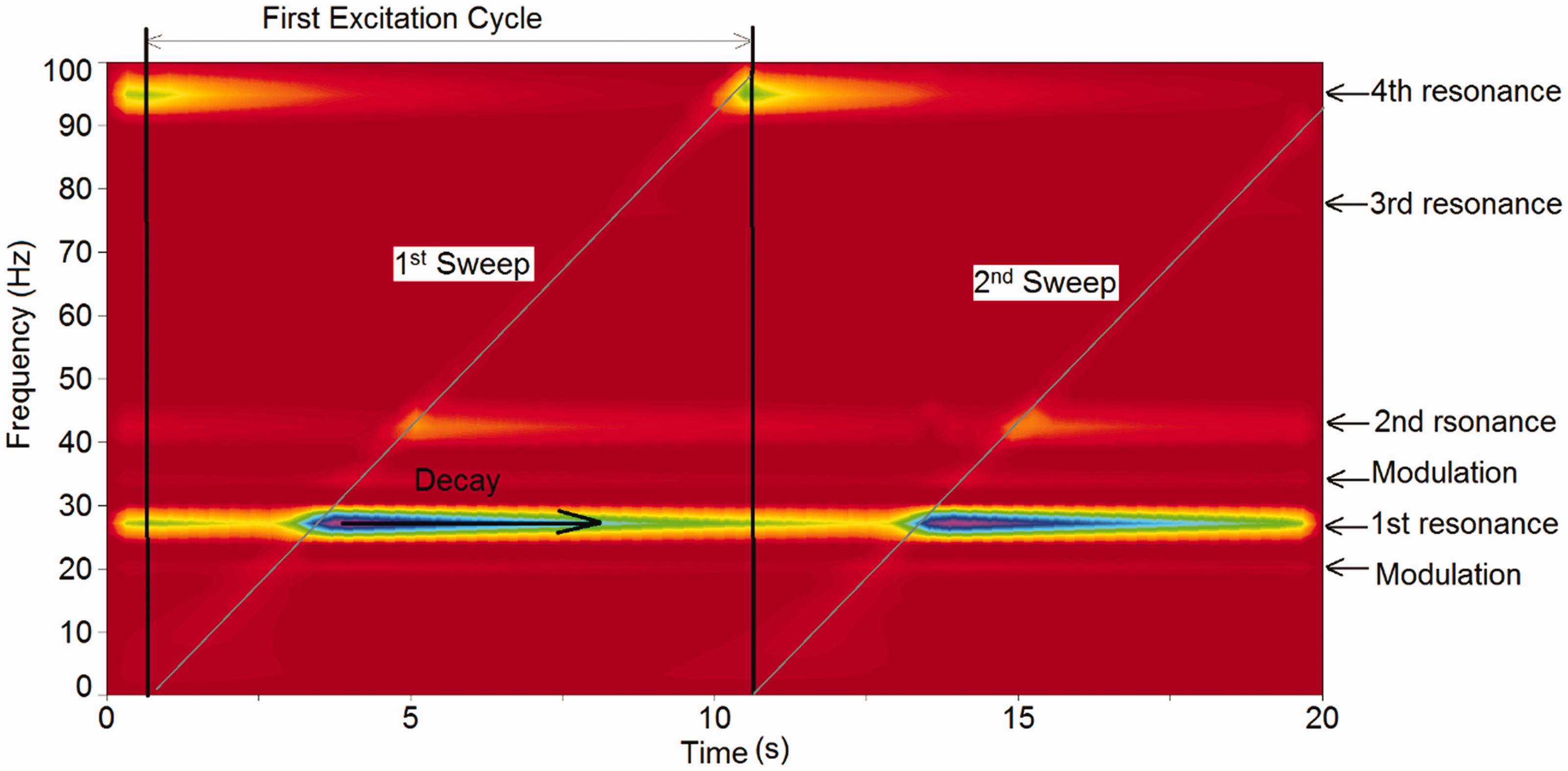
Figure 8 shows the displacement time history of the numerical excitation. The excitation function is designed to replicate the experimental excitation (applied by the shaker sweep) in both amplitude and frequency content.
Applied excitation sweep for numerical analysis.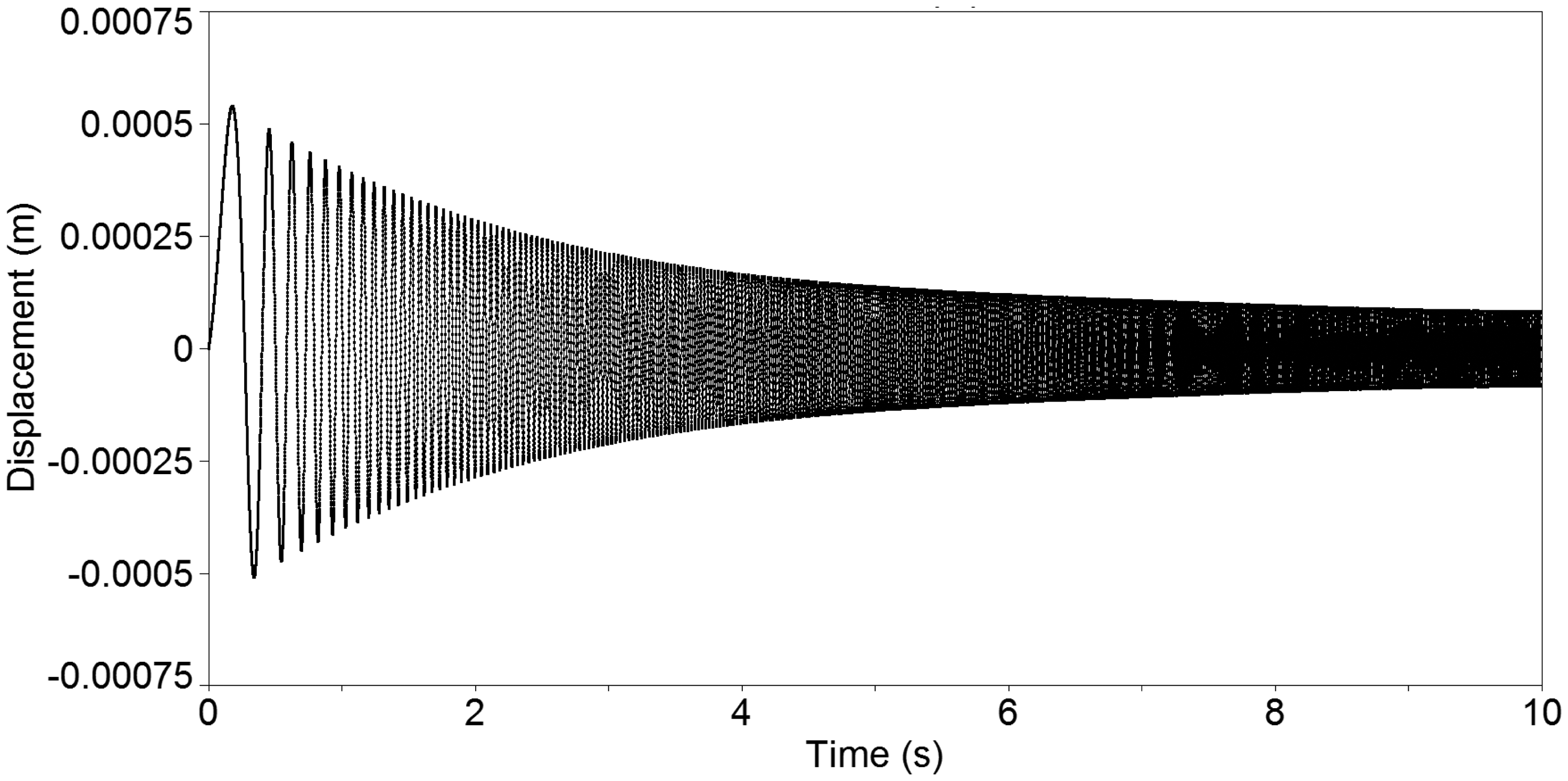
Applying this excitation function (section ‘Numerical Model’), Figure 8 shows the wavelet of the out-of-plane response of the ring at its free end gap, obtained through numerical prediction with the developed model. The first resonance acts at 24.5 Hz with the modulations occurring at 19 Hz and 30 Hz, respectively. The first mode dominates the ring's frequency response. The second mode at 42.1 Hz has significantly lower amplitude. The in-plane mode acts at 96.4 Hz and clearly couples with the out-of-plane mode as is discernible in the results of Figure 9.
Numerical prediction of ring out-of-plane response with excitation sweep of 1–100 Hz.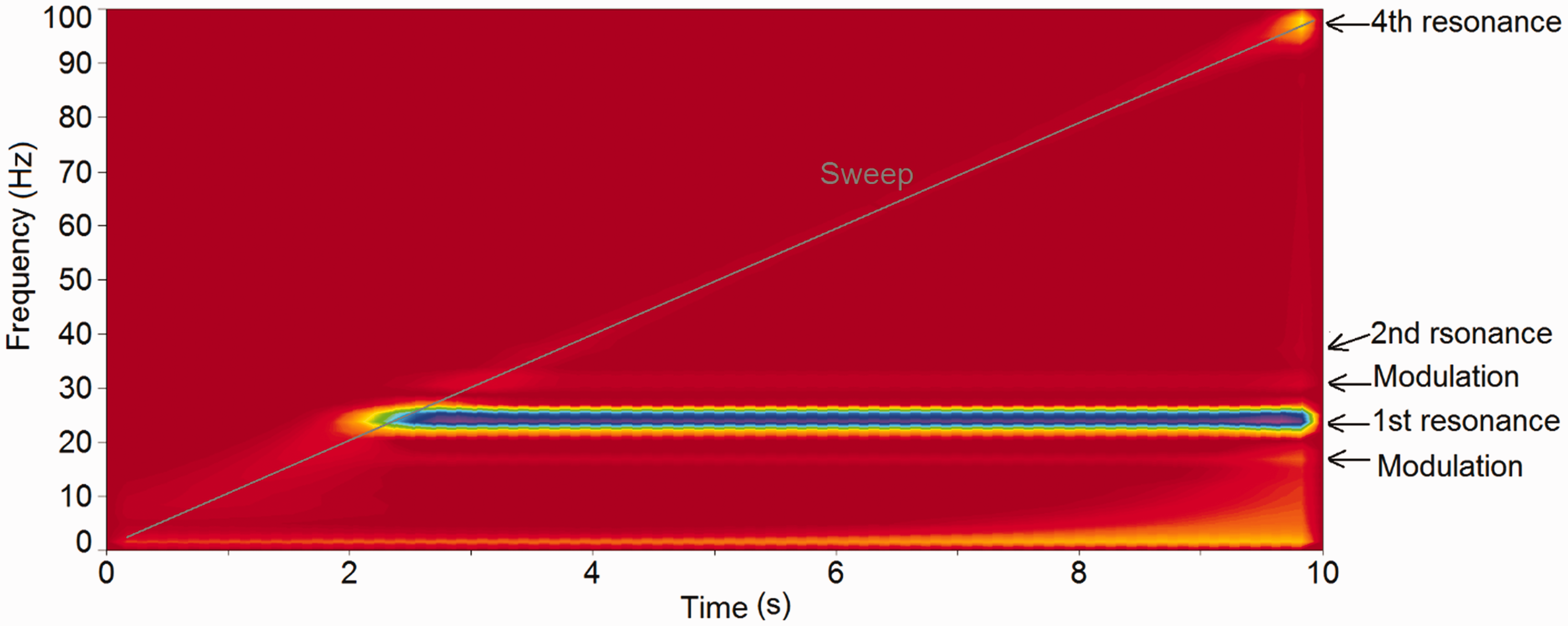
Figure 10 shows the in-plane response of the ring at its free end gap. The first response frequency is at 24.5 Hz with modulations at 19 Hz and 30 Hz, the same as those for the out-of-plane response. Clearly, this indicates the coupled in-plane and out-of-plane vibrations of a compression ring with a realistic cross-sectional form. These frequencies are the dominant responses of the ring in the axial out-of-plane direction. Their presence in the radial in-plane direction clearly demonstrates the flow of energy from one degree-of-freedom to another. The second out-of-plane mode at 42.1 Hz has minimal coupling with in-plane vibrations. The third response contribution in the in-plane spectrum is visible at 76.2 Hz (Figure 8). This agrees well with the experimental results. The fourth resonance at 96.4 Hz is a dominant in-plane response which flows into the out-of-plane domain as discerned in Figure 8.
Numerical prediction of ring in-plane response with excitation sweep of 1–100 Hz.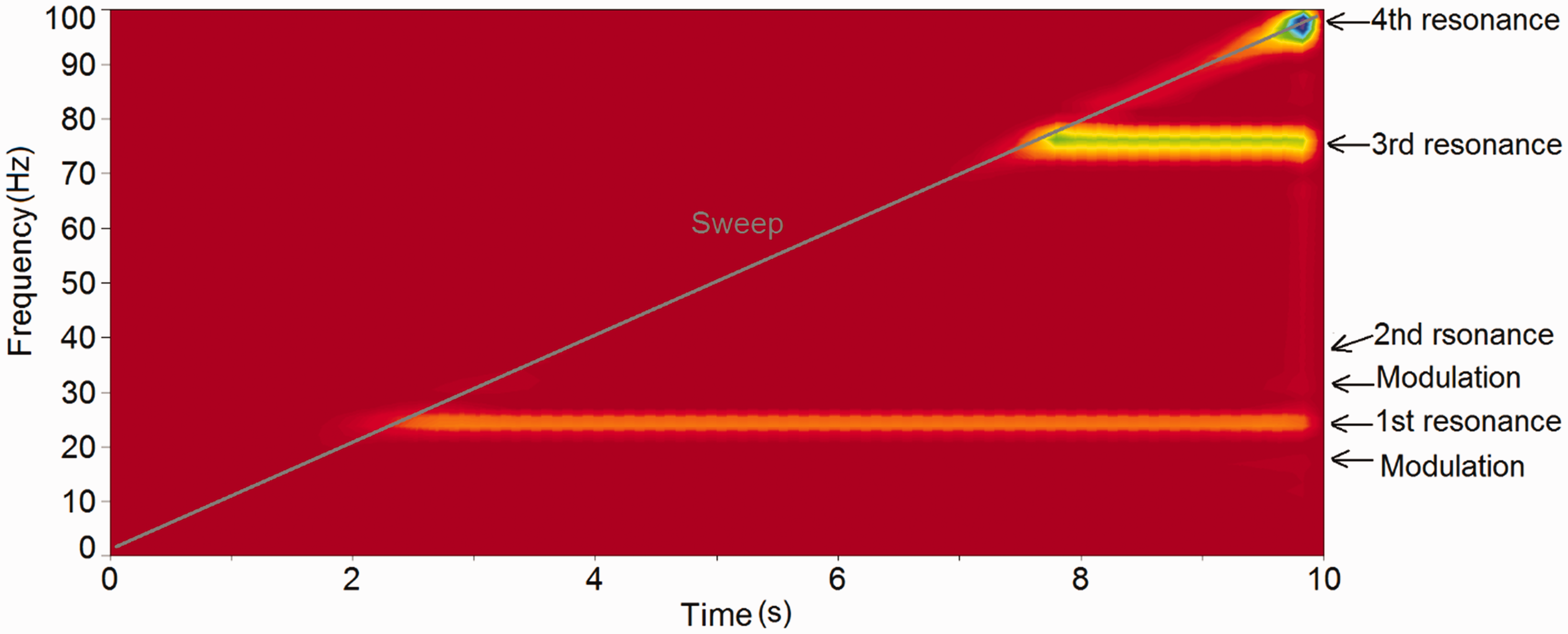
Comparison of frequency responses between the measurement and prediction.
Concluding remarks
A model is derived using finite difference discretisation of coupled Eulerian beam theory for a finite number of grids along an incomplete circular compression ring. The numerical model is applicable to compression rings with practical cross-sectional forms, where the shear centre does not coincide with the cross-sectional centroid. This takes into account the coupled in-plane radial and out-of-plane axial vibrations of the ring arising from a four degrees of freedom elastodynamic analysis. The presented model can also be applied to other ring types.
An experimental set up, comprising a clamped-free incomplete compression ring is used to excite the ring by a shaker with an amplitude-frequency sweep, which is also applied to the numerical model. The results of predictions show good conformance with measurements. This represents a component level validation step, which should be extended for the case of an in situ ring within a cylinder subjected to ring tension and pressure loading as well as with application of friction. This requires extension of experimental set up to a system-representative rig.
The results of both measurements and predictions show coupling of vibration between the in-plane and out-of-plane ring responses.
Footnotes
Acknowledgements
The authors would like to express their gratitude to the Engineering and Physical Science Research Council (EPSRC).
Declaration of Conflicting Interests
The author(s) declared no potential conflicts of interest with respect to the research, authorship, and/or publication of this article.
Funding
The author(s) disclosed receipt of the following financial support for the research, authorship, and/or publication of this article: The author would like to thank AVL List GmbH for the financial support of the reported research under the EPSRC-CDTei collaborative funding.