
Abstract
This work proposed a form of internal adjustable nonlinear connector that is used to couple the double-beam system. Employing the internal adjustable nonlinear connector as the basis, the model for analyzing the kinetic energy of vibration in the double-beam system coupled through the internal adjustable nonlinear connector has been developed and calculated its vibration kinetic energy responses by using the Galerkin truncation method (GTM). The effectiveness of the double-beam system coupled by the internal adjustable nonlinear connector is first investigated. On this basis, the impact and feasibility of the internal adjustable nonlinear connector on controlling vibration kinetic energy responses are discussed. From the numerical analysis, the effective working region of the internal adjustable nonlinear connector is determined. Furthermore, it can be found that the intricate dynamic behavior of the double-beam system appears at appropriate installation lengths of the internal adjustable nonlinear connector, in which the vibration energy transfer in the quasi-periodic state is characterized by a targeted energy transfer. There are differences in the effectiveness of the internal adjustable nonlinear connectors in controlling the vibration kinetic energy response at different excitation frequencies. Magnitudes of vibration kinetic energy can be efficiently regulated by adjusting the lengths at which the internal adjustable nonlinear connector is installed.
Keywords
Introduction
In various engineering fields, beams are employed to compose complex structures, including double-layer bridges, ocean platforms, and others. Inevitably, vibration excitations typically act on complex structures due to their working environment. Unfortunately, severe vibration issues may arise due to overly intense vibration stimulations. It is crucial to gain a comprehensive insight into the free and forced vibration properties of multiple beam vibration systems to guarantee that the vibrations in complex beam structures remain within safe limits.
In recent studies, academics have shown a strong interest in the vibration of system consisting of beams. In the early stage, Vu et al. 1 attempted to build the model for vibrational analysis of the double-beam system and then studied its forced vibration performance. Palmeri and Adhikari 2 developed the Galerkin-type state-space approach for determining the transverse vibrations of the double-beam system connected by a viscoelastic layer. Stojanović and Kozić 3 considered the influence of compressive axial load on the forced vibration of a double-beam system. Zhang et al. 4 studied the vibration features of a type of double-beam system that is linked through multiple spring-mass elements. Mao and Wattanasakulpong 5 systematically discussed the vibration of a double-beam system impacted by conservative and nonconservative axial loads. Mohammad and Hozhabrossadati 6 and Deng et al. 7 proposed the model of double functionally graded beams and calculated their vibration characteristics. Li et al. 8 built an ideal model of a modern beam structures and studied its dynamic behavior. Sourki and Hoseini 9 simplified the crack as the equivalent coupling element and built the double-beam system to simulate the situation of the cracked beam. Lee and Wang 10 employed the transfer matrix method to identify the slap phenomenon of the double-beam system connected by a partial coupling element. Hao et al. 11 developed a modified Fourier-Ritz method to calculate the free vibration of the generally restrained double-beam system. Mohammad et al. 12 employed a three-degree-of-freedom system to connect the double beam and discussed the impact of the three-degree-of-freedom on the mode shapes of the double beams. Li et al. 13 developed a state-space method to calculate the free and forced vibration of double-beam systems. Chen et al. 14 and Zhao et al. 15 studied the closed-from solutions for the forced vibration of a cracked double-beam system. Zhao 16 discussed the effect of concentrated mass on the vibration properties of a double-beam system. Zhao and Chang 17 investigated the vibration of generally constrained two beams connected both with the coupling layer and discrete points. Han 18 proposed a unified approach to predict the in-plane vibration of the two-beam system connected through translational springs. Li and Gong 19 built the theoretical model of the vibration system composed of multiple beams and studied its free and forced vibration. Zhou et al. 20 considered the variable cross-section double-beam system and studied its vibration characteristics. Stojanović et al. 21 studied the dynamic stability behavior of a coupled moving bogie system. Kadioglu and Yayli 22 studied the axial vibration of the FG nanobeam with arbitrary boundary conditions. The above literature broadens the research on the vibration characteristics of the beam system, promoting the engineering application of beam systems. Most of the studies in the above literature are based on linear vibration theory. However, nonlinear vibrations (magnitude-jumping, sensitivity to initial conditions, and others) are observed on various engineering occasions, suggesting that developing only the linear vibration theory cannot smoothly explain and control the vibration of the double-beam system.
As the demand for nonlinear vibration analysis intensifies, there has been a progressive shift in the focus of researchers toward the study of nonlinear vibrations in beam structures. Hajnayeb and Khadem 23 studied the nonlinear forced vibration of a double-walled carbon nanotube, in which they identified the system’s bifurcation points. Guo et al. 24 built the reduced model of the double inclined cables-deck beam and discussed its nonlinear forced vibration. Bochicchio et al. 25 investigated the nonlinear dynamic responses of a double-beam system that is buckled and interconnected by an elastic coupling layer. Hadian et al. 26 and Jazi 27 have extended the conventional couple stress theory, adapting it to investigate the nonlinear vibrational dynamics of a double nanobeam system that is joined through an elastic layer. Zhou et al. 28 studied the post-buckling behavior of axially moving beams under external loads and nonlinear vibration characterization. Milić et al. 29 studied the impact of discontinuity on the dynamic behavior of a nonlinear geometrical double-beam system. Sedighi et al. 30 systematically studied the nonlinear vibrations and chaotic behavior of curved two-layer beam-like structures, thereby promoting the application of such structures in the automotive industry. The above literature concentrates on studying and analyzing the nonlinear dynamic characteristics exhibited by diverse double-beam structures, in which nonlinearities of double-beam systems are mainly considered essential nonlinearity. Additionally, engineers have sought to leverage the properties of nonlinearities to manage unwanted structural vibrations, employing mechanisms such as nonlinear energy sinks31–34 and nonlinear supports.35–37 Wang et al. 38 and Kang et al. 39 studied the low-frequency vibration energy harvesting of the piezoelectric vibration system with an adjustable device based on the nonlinear vibration control theory, promoting the development of the vibration energy harvesting theory. In these applications, nonlinearities characterized by cubic stiffness features are commonly integrated into the design of nonlinear vibration control equipment.
Against this background, researchers have started to employ diverse types of nonlinearities characterized by cubic stiffness to regulate the vibrations in beam systems. On one hand, the literature used cubic stiffness nonlinearities to design nonlinear energy sinks.40–46 Then, researchers put nonlinear energy sinks into boundaries or internal beams to reduce their vibration magnitudes. On the other hand, cubic stiffness nonlinearities were employed to design nonlinear supports, which were installed on boundaries or internal beams to improve their isolation effectiveness or control their vibration magnitudes.47–52 Furthermore, cubic stiffness nonlinearities were also designed as coupling nonlinear elements, including nonlinear coupling layer,53–57 nonlinear coupling stiffness,58–60 and coupling nonlinear spring-mass systems,61–68 which were employed to connect double beams and control their nonlinear dynamic behavior.
The above literature has targeted the investigation of the nonlinear dynamic responses of double-beam structures, employing these nonlinear characteristics to design nonlinear equipment for the suppression of beam vibration. The majority of studies paid attention to vibration control of beams attached with nonlinear energy sinks and nonlinear supports, whereas double beams interconnected by coupling nonlinear elements have garnered relatively scant scholarly attention. Meanwhile, few studies discussed the concrete realization form of coupling nonlinear elements, which limits their engineering application. Additionally, research seldom studies the adjustable coupling nonlinear element.
In response to the aforementioned constraints, this work considers the concrete realization form of nonlinear coupling elements and proposes a theoretical model for an internal adjustable nonlinear connector which is applied to couple the double-beam system. Then, an analysis model for the forced vibration of a double-beam system coupled by the internal adjustable nonlinear connector is constructed, in which the Galerkin truncation method (GTM) is employed to calculate its forced vibration responses. The validation of the double-beam system coupled through the internal adjustable nonlinear connector is first studied. On this basis, the impact and feasibility of the internal adjustable nonlinear connector on controlling vibration kinetic energy responses of the double-beam system are discussed.
Theoretical formulations
Model description
Figure 1 illustrates the schematic of a double-beam system interconnected by means of an internal adjustable nonlinear connector. The vibration system depicted in Figure 1 is comprised of sub-beam 1, sub-beam 2, the internal adjustable nonlinear connector element, and restraining springs. The internal adjustable nonlinear connector is installed inside the double-beam system. The double-beam system incorporates an internal adjustable nonlinear connector, which is constructed from a combination of working springs, connecting springs, supporting springs, coupling mass, and viscous damping, where z denotes the quantity of working springs and uE(t) is its motion displacement. The vibration displacement of each sub-beam is denoted by u1(x1,t) and u2(x2,t), respectively. Constraint springs are positioned at the boundaries of the double-beam system to establish elastic boundary conditions. In this work, external excitation acting on the double-beam system is set as the form of point harmonic, which is acting on the right end of sub-beam 1. F0 is the magnitude and ω is the angle frequency of the external excitation. Furthermore, Table 1 defines parameters belonging to sub-beams. Table 2 defines parameters belonging to the internal adjustable nonlinear connector. Diagram of the double-beam system coupled through an internal adjustable nonlinear connector. The definition of parameters belonging to sub-beams. The definition of parameters belonging to the internal adjustable nonlinear connector.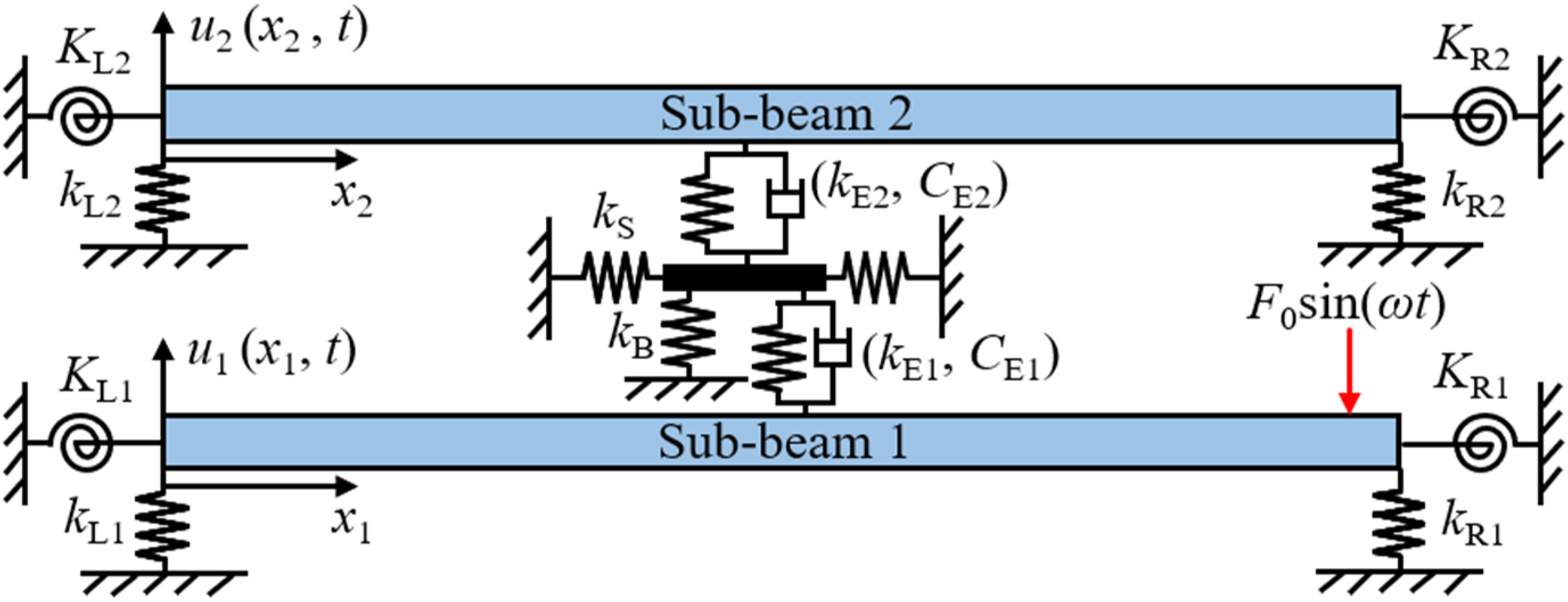
Equation derivation
This section derives the governing equations of the double-beam system, which is coupled through an internal adjustable nonlinear connector. Figure 2 gives the diagram of the internal adjustable nonlinear connector with an assumed displacement. In the model of the adjustable nonlinear connector shown in Figure 2, the working springs are installed within the internal adjustable nonlinear connector, where the installation length of the working springs differs from their original length. To calculate the nonlinear restoring force generated during the vibration processes of the adjustable nonlinear connector, the original length of the working springs must be defined. According to Section 2.1, LS is the installation length of working springs. LS0 is the original length of working springs. Diagram of the internal adjustable nonlinear connector with an assumed displacement.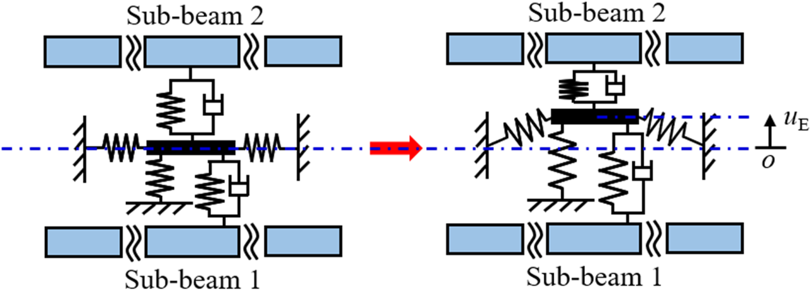
Then, analyzing the force relation in Figure 2, the force acting on the coupling mass is derived as,
Expanding equation (1) by using the Maclaurin form of Taylor’s formula, equation (1) can be approximately derived as,
It should be noted that minor deviations or uncertainties exist in the process of simplifying the equivalent nonlinear stiffness of the internal adjustable nonlinear connector. To guarantee the force predicted by equation (2) matches well with that obtained by equation (1), the motion displacement of the internal adjustable nonlinear connector and installation length of working springs must satisfy the relation |uE| ≤ 0.2LS, 50 which will be explained in Section 3.1. In the subsequent theoretical analysis, the displacement of the internal adjustable nonlinear connector is monitored in each analysis result to ensure it remains within the effective range |uE| ≤ 0.2LS.
From equation (2), the force acting on the internal adjustable nonlinear connector presents the cubic stiffness characteristic. The nonlinear stiffness of the adjustable nonlinear connector can be adjusted by changing the installation length of the working springs. Furthermore, in the working state, the working springs are always kept in a compressed condition, which will introduce negative stiffness to the vibration system. The supporting spring is installed on the internal adjustable nonlinear connector element to dismiss the negative stiffness generated by the working springs, whose stiffness adheres to the relation in the following.
Putting equation (3) into equation (2), the force acting on the coupling mass is simplified as,
Therefore, the motion equation of the internal adjustable nonlinear connector is derived as,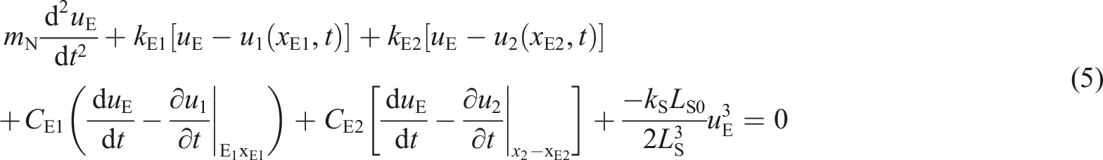
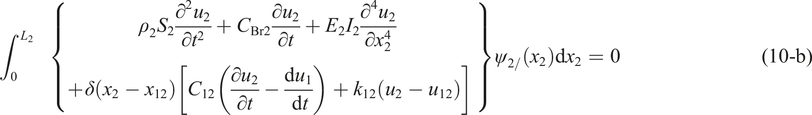
Then, according to the vibration theory and Newton’s second law, vibration-governing equations of sub-beams are derived as,

The equations that govern the boundaries of sub-beam 1 are derived as follows,

The equations that govern the boundaries of sub-beam 2 are derived as follows,

By employing the motion equation of the internal adjustable nonlinear connector to solve the governing equations of sub-beams, forced vibration of the double-beam system coupled via the internal adjustable nonlinear connector can be determined.
It should be noted that the internal adjustable nonlinear connector shown in Figure 2 can be realized using basic engineering units. Fortunately, some classic automatic centering devices can be used to achieve the design of adjustable spring devices. For example, a self-centering device designed based on the Archimedean spiral. The custom new device includes an Archimedean-helical-planar gear structure and sliders. By connecting the horizontal springs shown in Figure 2 to the slider of the self-centering device, the movement of the slider can be controlled by rotating the Archimedean-helical-planar gear structure, thereby adjusting the length of the horizontal spring. On this basis, the overall equivalent nonlinear stiffness of the device can be effectively changed. Reference 42 studied the feasibility of the related device. Thus, it can be determined that the internal adjustable nonlinear connector can be realized in engineering practice.
Solution procedure
This section employs the GTM to obtain the vibration kinetic energy of the double-beam system coupled by the internal adjustable nonlinear connector. In GTM, vibration displacements of sub-beams are expressed as follows,

Terms in equation (9) related to x1 and x2 are the mode functions of sub-beams, which are defined as the trail functions. Terms in equation (9) related to t are the undetermined time coefficients waiting for prediction. It should be noted that the core of the theoretical solution involves solving the time domain terms corresponding to each order of mode. The order of modal expansion will affect the accuracy of the numerical results. Generally, within a specified frequency range, once the modal expansion order reaches a specific value, continuously increasing the modal order will not improve the accuracy of the calculation results. Unfortunately, blindly increasing the modal expansion will also increase the computational cost. The influence of the order of modal expansion on the system’s dynamic behavior is typically studied. Subsequently, a critical mode expansion order is selected and used to solve the dynamic behavior of the subsequent beam system.
Using the Galerkin condition to discretize the vibration-governing equations of sub-beams, namely,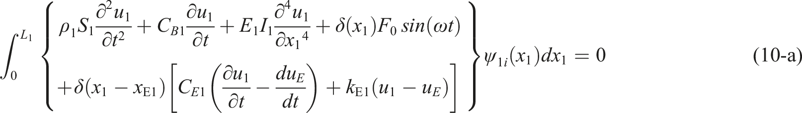
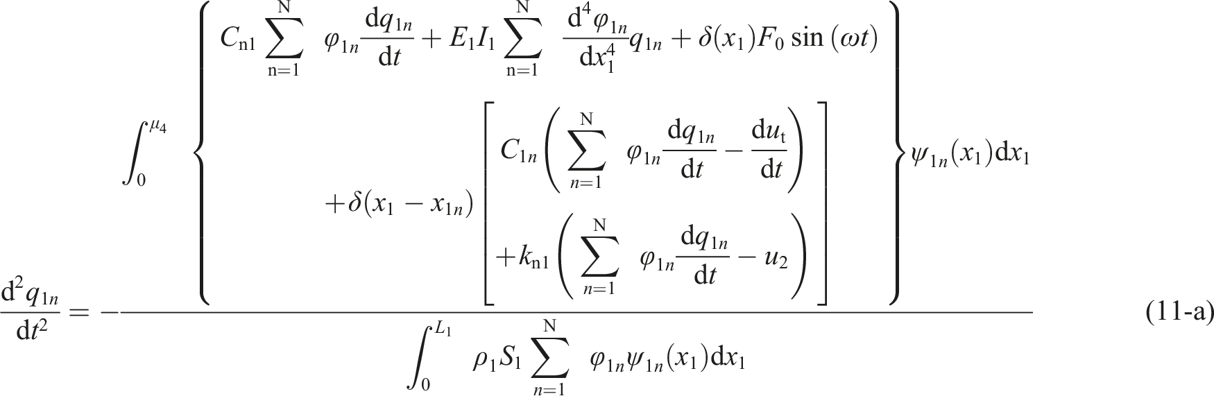
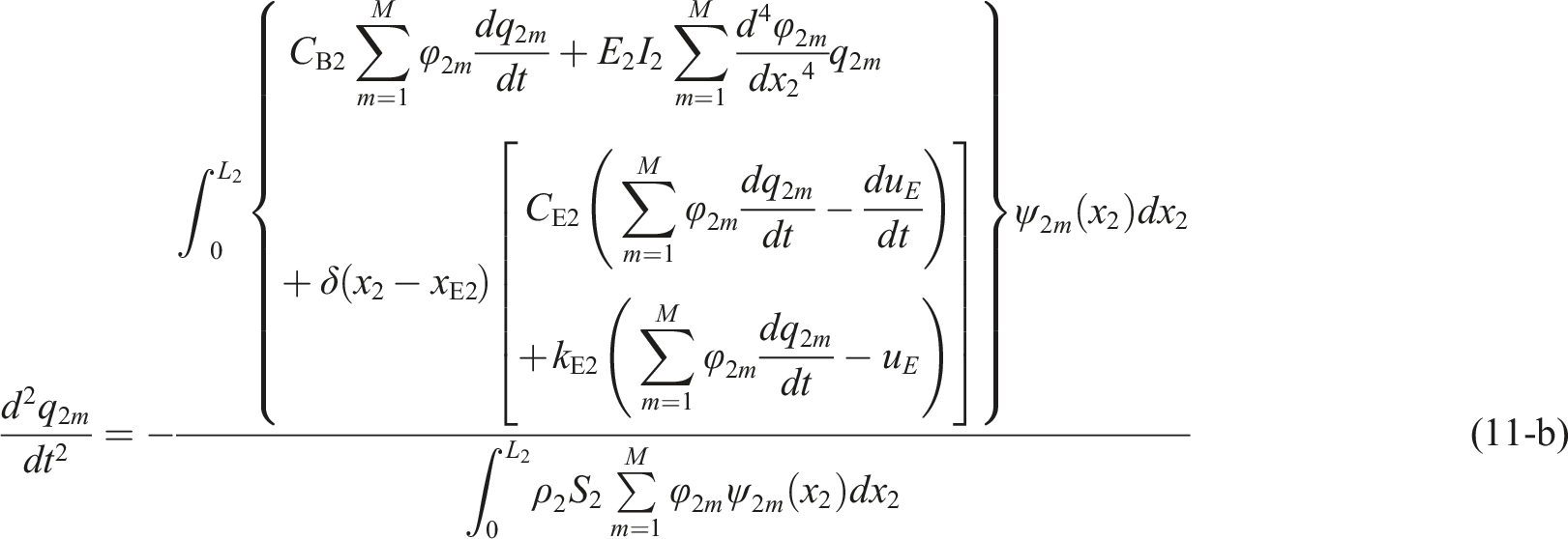
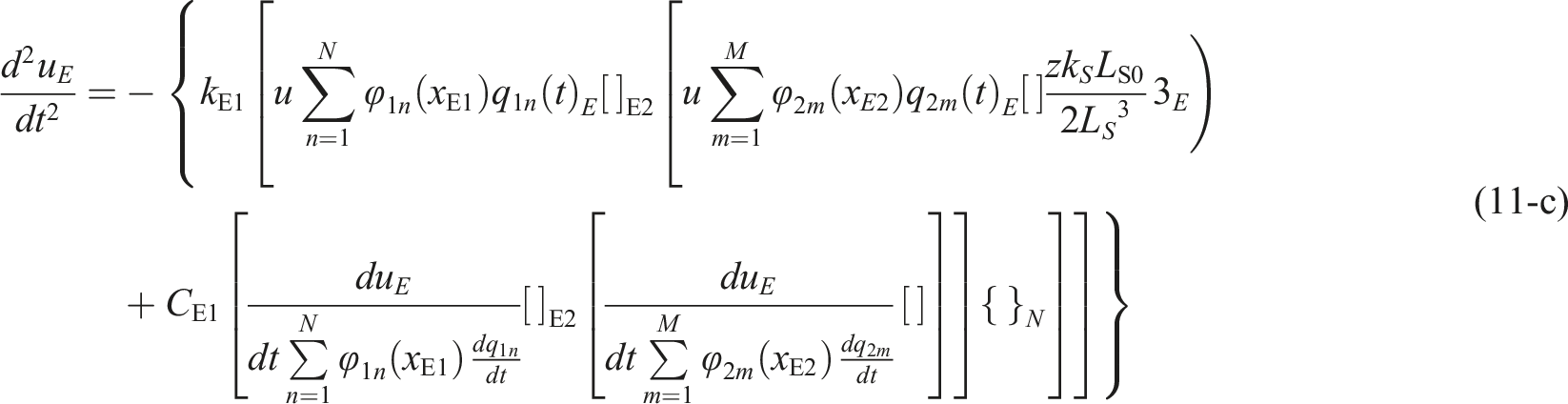
Undetermined time terms can be gained by numerically solving equation (11). In this work, the Runge-Kutta approach is employed to solve the above equations. Then, vibration responses of the double-beam system coupled through the internal adjustable nonlinear connector can be gained.
Numerical results and discussion
This study discusses the numerical results of the vibration kinetic energy belonging to the double-beam system coupled through an internal adjustable nonlinear connector. In this section, the time domain in calculating numerical results is [0, 2000 TE], where TE is the period of the harmonic excitation. Numerical results in the domain [1801 TE, 2000 TE] are viewed as a response of a stable state without transient dynamic behavior. It should be noted that the internal adjustable nonlinear connector is a nonlinear coupling element, where the nonlinear restoring force is introduced into the double-beam system. The magnitude of the nonlinear restoring force determines the working characteristics of the internal adjustable nonlinear connector. Generally, the magnitude of the nonlinear restoring force is determined by the nonlinear stiffness and relative vibration displacement between sub-beams. When the boundaries of the double-beam system changed, the relative vibration displacement between sub-beams also changed. Thus, the magnitude of the nonlinear restoring force acting on the double-beam system must vary for different boundary conditions. Changes in the boundary conditions of the double-beam system must cause variations in the system’s dynamic behavior. To ensure the generality of the research, this paper deliberately selects a set of general boundary conditions.
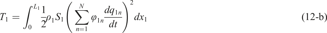
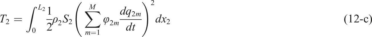
Furthermore, the parameters of sub-beams structures are listed as follows: E1 = 6.89×10¹⁰ Pa, E2 = 2.11×10¹¹ Pa, ρ1 = 2.8×10³ kg/m3, ρ2 = 7.85×10³ kg/m3, S1 = S2 = 2×10⁻⁴ m2, I1 = I2 = 1.6667×10⁻⁹ m4, L1 = L2 = 1 m, z = 8, F0 = 10 N, kL1 = kL2 = 5×10⁴ N/m, kR1 = kR2 = 5×10³ N/m, KL1 = KL2 = 104 Nm/rad, and KR1 = KR2 = 103 Nm/rad. Furthermore, to study the vibration of the double-beam system coupled through the internal adjustable nonlinear connector from a general angle, the vibration kinetic energy of the double-beam system is chosen as the research target. It is worth mentioning that the first derivative of undetermined time terms is also gained in the numerical procedure of GTM, which can be employed to obtain the vibration kinetic energy of the double-beam system. The specific expression of the vibration kinetic energy belonging to the internal adjustable nonlinear connector and sub-beams are derived as follows:
Validation study
First, this section focuses on validating the relationship between uE and LS. Figure 3 gives nonlinear force introduced by working springs, where the real value is calculated by equation (1) while the equivalent value is calculated by equation (2). In this numerical example, kS = 107 N/m and LS0 = 0.15 m. From Figure 3, the real value and the equivalent value of the force introduced by working springs match each other smoothly during the area [−0.2 LS, 0.2 LS]. Out of the above area, the difference between the real value and the equivalent value of the force introduced by working springs can be observed. Furthermore, with the continuous growth of uE/LS, the difference between the actual value and the equivalent value also expands. Therefore, to guarantee the validation of equation (2), uE and LS must satisfy the relation |uE| ≤ 0.2LS. In the subsequent study, the monitor value is introduced to monitor the validation of the internal adjustable nonlinear connector, which is defined as Force introduced by working springs.
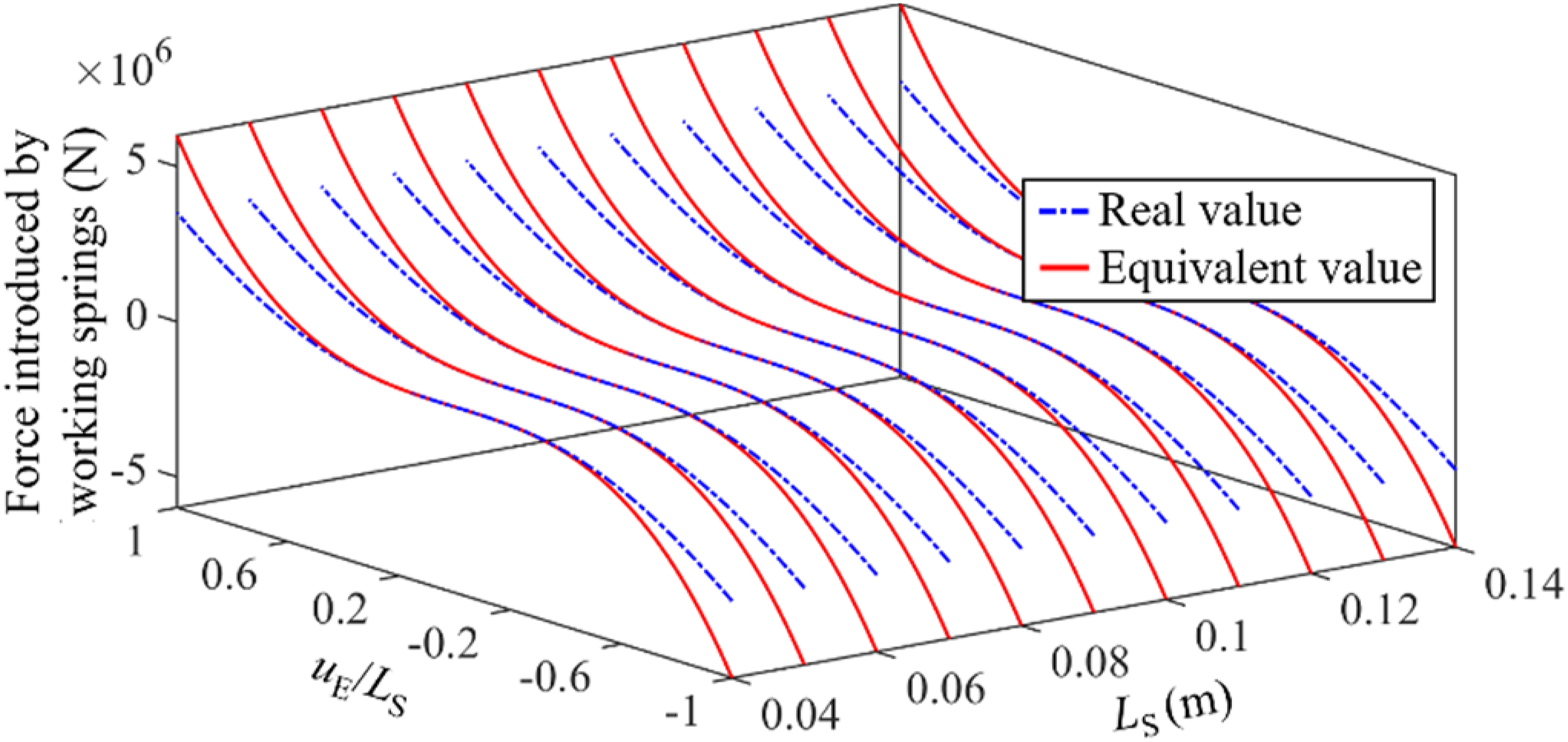
The values of LS and its corresponding range of |uE|.
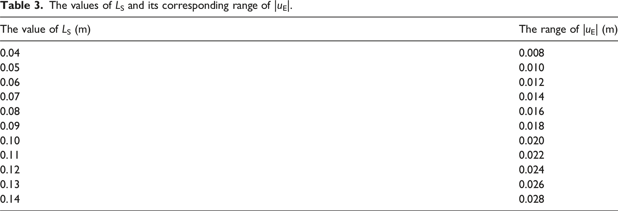
Second, the correctness and stability of vibration kinetic energy obtained by the GTM are discussed. Figure 4 illustrates the comparative analysis of the vibrational kinetic energy as calculated through various approaches, which include the GTM, harmonic balance method (HBM), and Lagrange method (LM). In this numerical example, kS = 107 N/m, kE1 = kE2 = 104 N/m, CE1 = CE2 = 1 Ns/m, LS = 0.12 m, xE1 = xE2 = 0.5 m, and 4-term truncation number. Furthermore, the reference value for vibrational kinetic energy is set at 10-12 J. From Figure 4, the vibration kinetic energy responses calculated by different methods fit smoothly. Importantly, the modeling processes of the GTM and LM are different, while the solving processes of the HBM and GTM are also different. The above phenomenon indicates that the same numerical results are obtained by using different methods, concluding that the vibration kinetic energy of the double-beam system coupled through the internal adjustable nonlinear connector calculated by the GTM is correct. Comparison of the vibrational kinetic energy calculated by different approaches.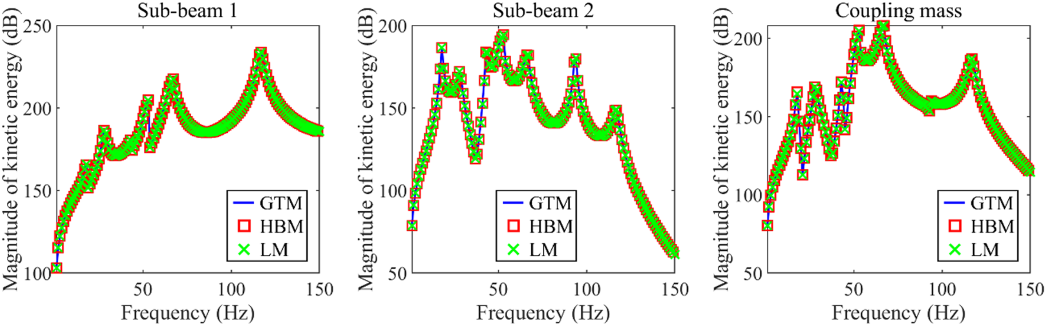
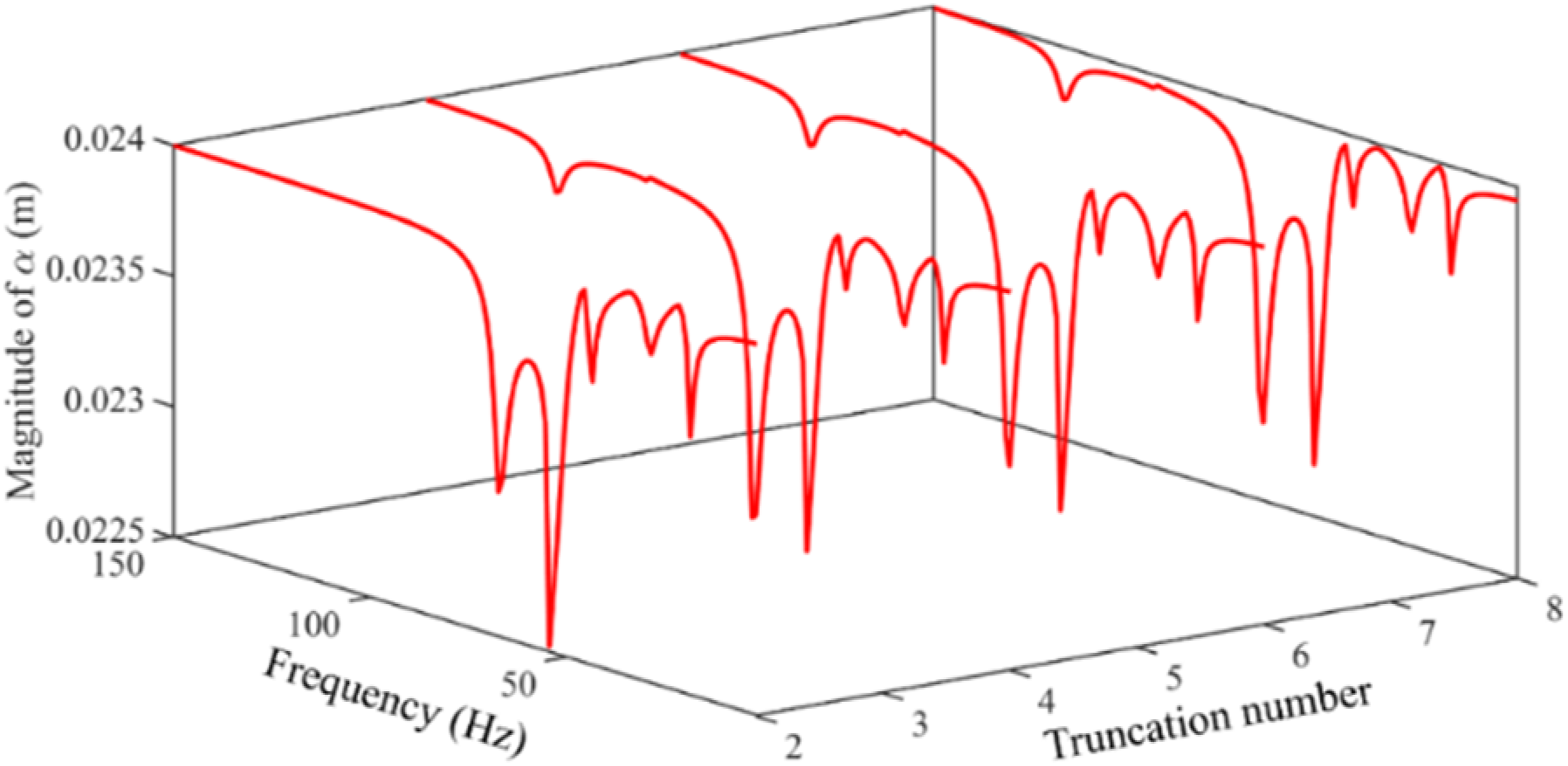
Then, the stability of vibrational kinetic energy obtained by the GTM is investigated. Figure 5 presents the vibration kinetic energy responses of the double-beam system coupled through the internal adjustable nonlinear connector under different truncation numbers. From Figure 5, the number of resonance regions and the stability of the vibrational kinetic energy response are affected by truncation numbers. Meanwhile, the vibration kinetic energy responses remain stable under the 6-term truncation number. In Sections 3.2 and 3.3, the 6-term truncation number is employed in calculating the vibration kinetic energy responses of the double-beam system coupled with the internal adjustable nonlinear connector. Furthermore, Figure 6 gives the magnitude of ɑ belonging to the double-beam system coupled with the internal adjustable nonlinear connector, where the parameters of the double-beam system are the same as those used in Figures 4 and 5. From Figure 6, the magnitude of ɑ is greater than 0 under the whole frequency calculation domain, verifying the validation of the numerical results shown in Figures 4 and 5. The responses of vibrational kinetic energy as influenced by varying truncation numbers. Magnitude of ɑ in the calculating frequency domain.
Vibration kinetic energy with the change of frequency
Considering the internal adjustable nonlinear connector established in Figure 1, this section explores the feasibility of controlling vibration kinetic energy responses through modification parameters of the internal adjustable nonlinear connector. At first, the effective control parameters of the internal adjustable nonlinear connector must be figured out. From equation (5), the motion equation of the internal adjustable nonlinear connector is related to mN, CE1, CE2, kE1, kE2, kS, LS0, LS, and z. However, considering the engineering convenience, only several parameters of the internal adjustable nonlinear connector are suitable for vibration control. Due to the limitation of installation ways, mN, kE1, kE2, kS, LS0, CE1, and CE2 are difficult to adjust once the internal adjustable nonlinear connector is installed between sub-beam 1 and sub-beam 2. Therefore, it is unwise to adjust the above parameters. Fortunately, for the internal adjustable nonlinear connector, the nonlinear force introduced by working springs is related to LS, which means that adjusting LS can effectively change the nonlinear force of the internal adjustable nonlinear connector. Against the above background, this section concentrates on the influence of LS on the vibrational kinetic energy responses in the double-beam system.
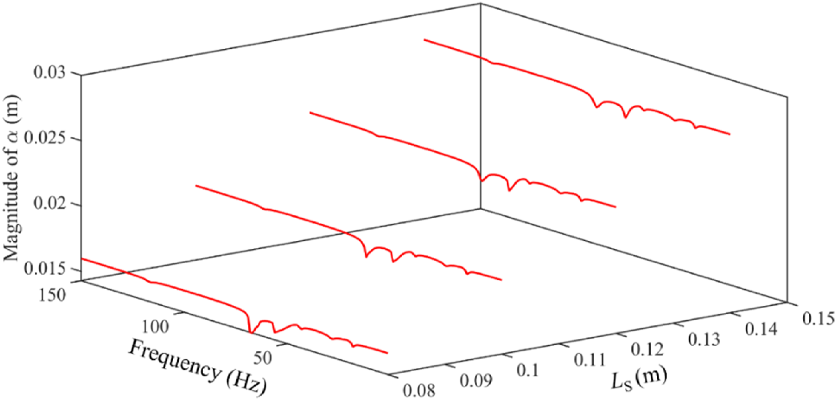
Figure 7 gives the vibration kinetic energy responses under different LS. When kS = 0 N/m, the internal adjustable nonlinear connector degrades into a linear connector. From Figure 7, the alteration of LS belonging to the internal adjustable nonlinear connector greatly impacts the vibration kinetic energy responses of the vibration system. In terms of vibration reduction, the decrease of LS is good for the vibration reduction at two resonance areas, including the 5th primary resonance area of sub-beam 1 and the 4th primary resonance area of sub-beam 2. In contrast, the growth of LS is good for the vibration reduction at the 4th primary resonance area of sub-beam 1 and the 5th primary resonance area of sub-beam 2. Out of the above resonance areas, the change of LS slightly impacts the vibration reduction of each sub-beam. From the angle of frequency transfer, the decrease of LS expands the width of the 4th primary resonance area, indicating that the aforementioned resonance zone migrates to a higher frequency domain as the value of LS is reduced. From the angle of vibration states, complex dynamic behavior appears in vibration kinetic energy responses under certain parameters of LS. On one hand, the magnitude of the vibration kinetic energy responses jumps suddenly in the 4th primary resonance area. On the other hand, a zone characterized by a succession of continuous amplitudes is observed in close proximity to the 5th primary resonance region of the vibrational kinetic energy responses. Decreasing LS expands the width of the zone characterized by a succession of continuous amplitudes. The reason for the above phenomenon can be explained as follows. The internal adjustable nonlinear connector is a nonlinear coupling element, where the nonlinear restoring force is introduced into the double-beam system. The magnitude of the nonlinear restoring force determines the working characteristics of the internal adjustable nonlinear connector. Generally, the magnitude of the nonlinear restoring force is determined by the nonlinear stiffness and relative vibration displacement between sub-beams. For the same resonance regions, the vibration magnitude of the double-beam system remains at the same level under different equivalent nonlinear stiffnesses of the internal adjustable nonlinear connector. Therefore, to change the nonlinear restoring force acting on the double-beam system, it is wise to change the LS of the internal adjustable nonlinear connector. In this work, decreasing LS expands the equivalent nonlinear stiffnesses, while increasing LS shrinks the equivalent nonlinear stiffnesses. On this basis, changing the LS of the internal adjustable nonlinear connector significantly impacts the nonlinear restoring force acting on the double-beam system, thereby motivating the system’s complicated dynamic behavior. Additionally, compared to the linear connector, it can be found that introducing the internal adjustable nonlinear connector has a positive impact on the vibration suppression under several resonance regions of the double-beam system. According to the above analysis, the vibration kinetic energy responses of the double-beam system can be effectively controlled by changing the installation length of the internal adjustable nonlinear connector. Furthermore, Figure 8 gives the magnitude of ɑ belonging to the double-beam system coupled through the internal adjustable nonlinear connector, where the parameters of the double-beam system are the same as those used in Figure 7. As depicted in Figure 8, the value of ɑ is greater than zero under the whole frequency calculation domain, verifying the validity of the numerical results shown in Figure 7. Vibration kinetic energy responses under different LS. Magnitude of ɑ in the calculating frequency domain.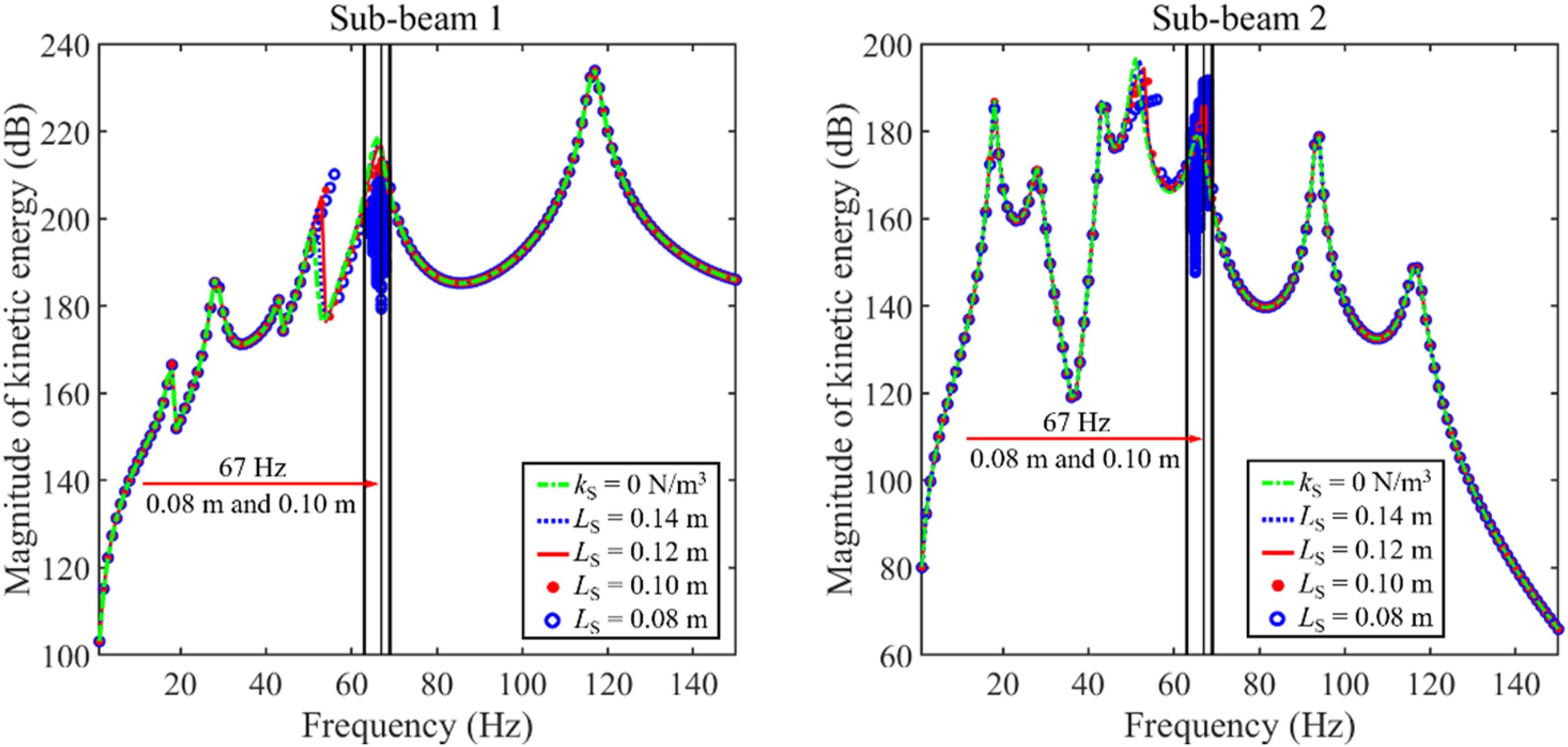
To figure out the specific vibration characteristics of the area featuring multiple continuous amplitudes, Figure 9 gives the phase trajectory and Poincaré points associated with the region of successive amplitudes in Figure 7, where observation position 1 is x1 = 0.5 m while observation position 2 is x2 = 0.5 m. It can be observed from Figure 9 that the phase trajectory in each subfigure continues to be stable while Poincaré points come to make a whole closed curve. According to the above phenomena, it can be concluded that the area characterized by a succession of continuous amplitudes is vibrating in the quasi-periodic state. The appearance of complex dynamic behavior means that the original vibration characteristics of the double-beam system are changed by introducing the adjustable coupling nonlinear connector. Phase trajectory and Poincaré points of the complex dynamic behavior in Figure 7.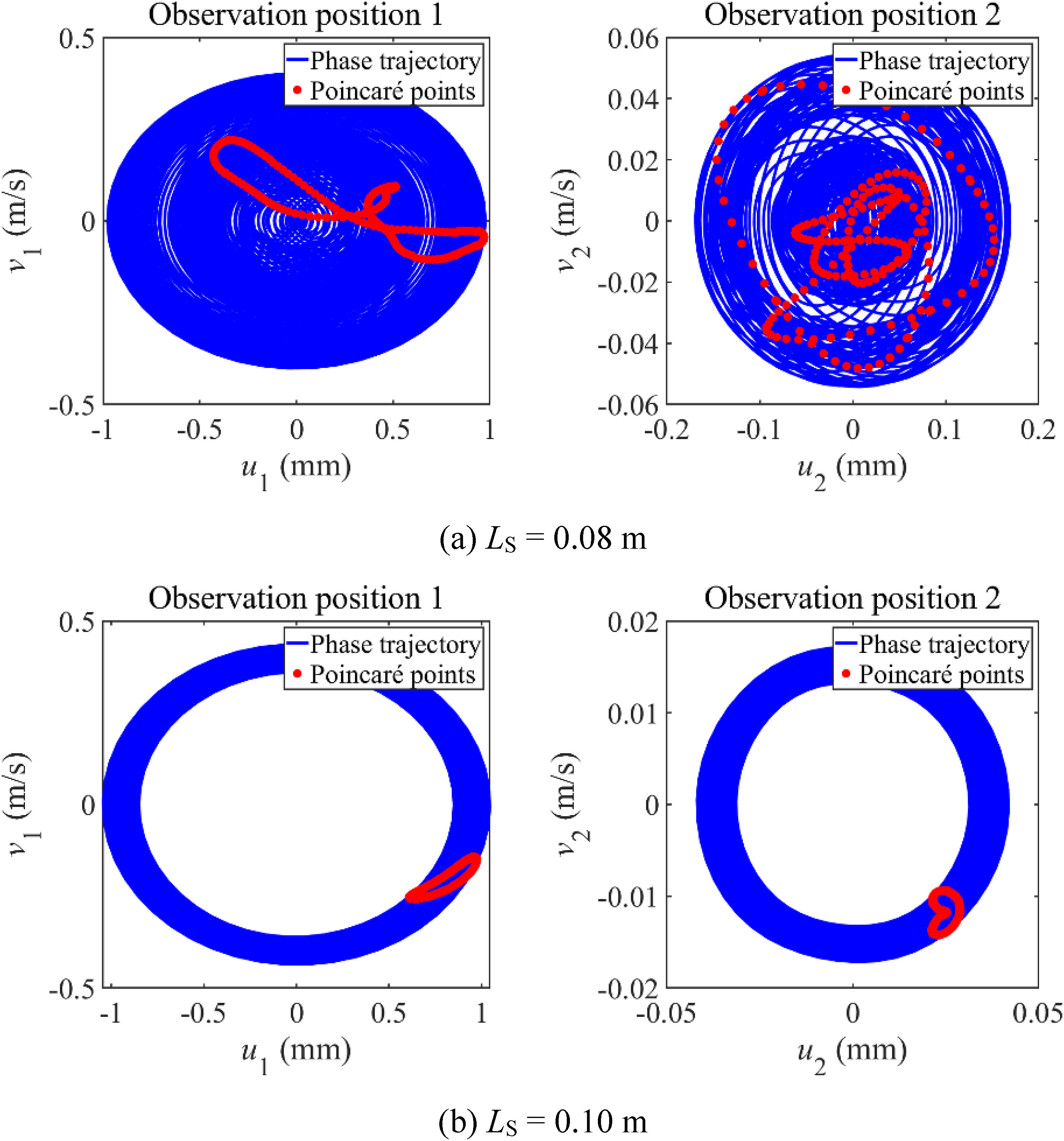
Furthermore, according to the analysis related to Figures 7 and 9, it can be speculated that the characteristic of vibrational kinetic energy transfer in the quasi-periodic state differs from that in the single-periodic condition. To explore the vibration kinetic energy transfer characteristic of the quasi-periodic state, Figure 10 charts the time progression of the vibration kinetic energy under the single-periodic state and the quasi-periodic state. From Figure 10, under the single-periodic state, the time progression of the vibration kinetic energy associated with sub-beams and the internal adjustable nonlinear connector remains stable. In contrast, under the quasi-periodic state, magnitudes of the vibration kinetic energy belonging to sub-beams and the internal adjustable nonlinear connector oscillate periodically. From the above phenomena, the vibration kinetic energy of the quasi-periodic state appears to transfer periodically between sub-beams and the internal adjustable nonlinear connector. Time progression of the vibration kinetic energy.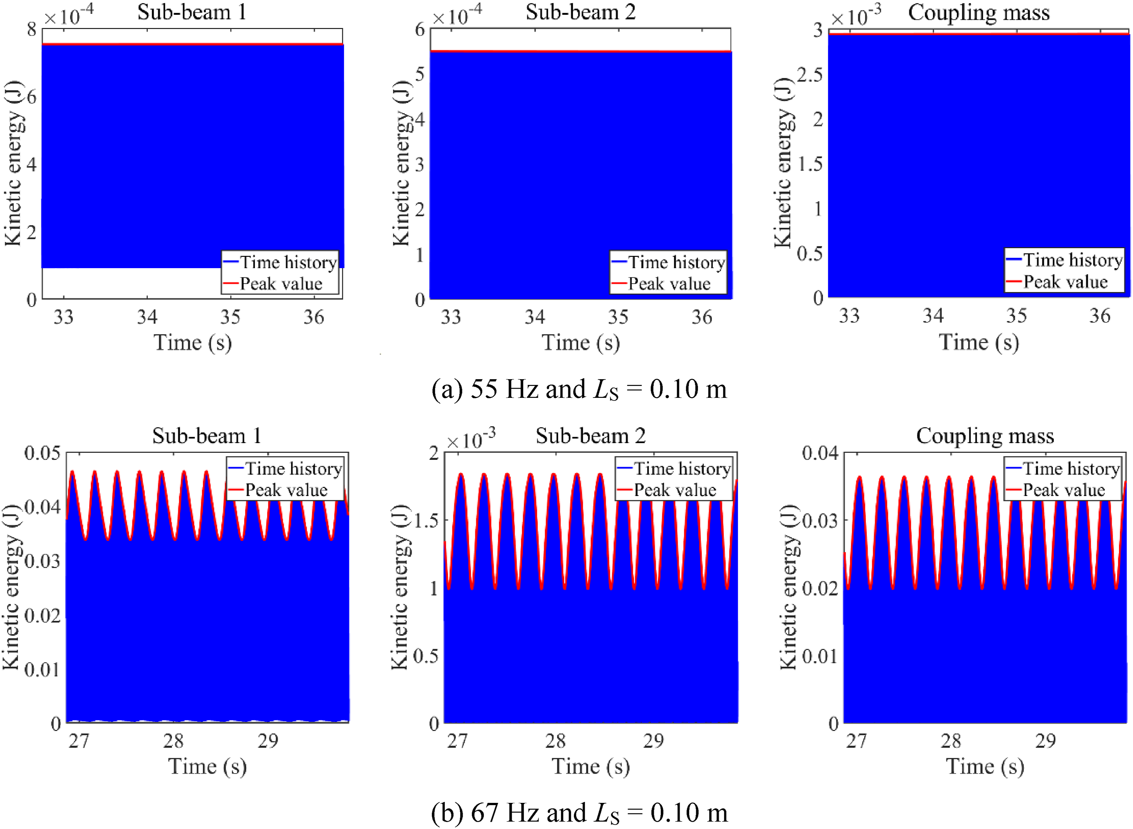
Then, Figure 11 gives peaks of the vibration kinetic energy under the single-periodic state and the quasi-periodic state. According to Figure 11, peaks of the vibrational kinetic energy under the single-periodic state are constant, illustrating that the vibrational kinetic energy of sub-beams and the internal adjustable nonlinear connector keeps stabilizing. Peaks of the vibrational kinetic energy under the quasi-periodic state oscillate periodically. Within the cyan region, the peaks corresponding to the vibrational kinetic energy of sub-beam 1 reduce progressively, whereas those associated with the coupling mass grow monotonously, implying that the vibrational kinetic energy of sub-beam 1 is targeted to transfer to the internal adjustable nonlinear connector. Conversely, the vibration kinetic energy of the internal adjustable nonlinear connector is targeted to transfer to sub-beam one within the gray zone. However, the peaks of vibration kinetic energy associated with the internal adjustable nonlinear connector and sub-beam 2 oscillate synchronously, indicating the absence of a targeted energy transfer phenomenon between sub-beam 2 and the internal adjustable nonlinear connector. From the above analysis, it can be found that the internal adjustable nonlinear connector can alter the vibration energy transfer characteristic of the double-beam system. Furthermore, the quasi-periodic state corresponds to the targeted energy transfer, which can be defined as the mark of the targeted energy transfer appearance between sub-beam 1 and the internal adjustable nonlinear connector. Peaks of the vibration kinetic energy.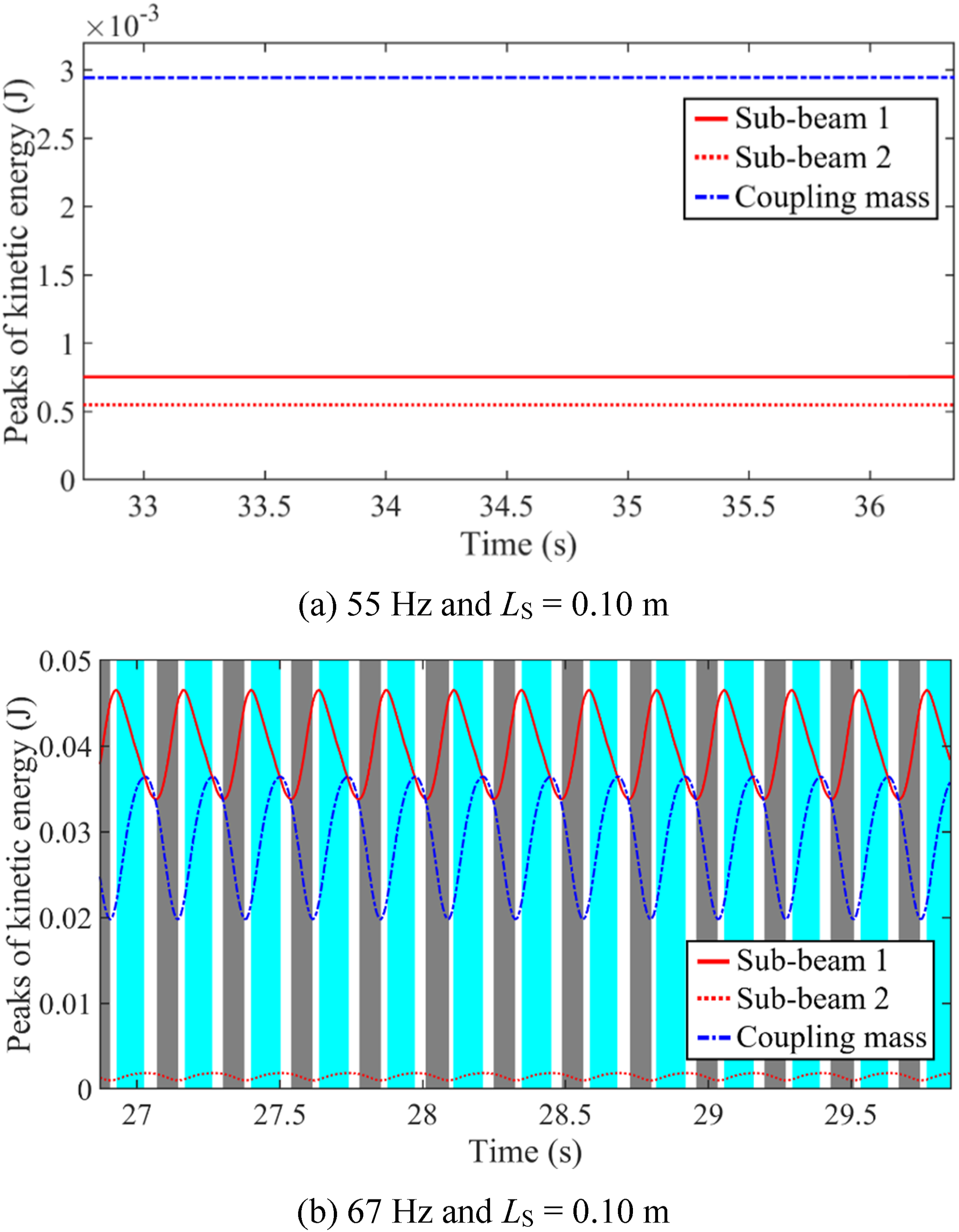
Importantly, the generation mechanism of the quasi-periodic vibration can be explained as follows. The internal adjustable nonlinear connector is a nonlinear coupling element, where the nonlinear restoring force is introduced into the double-beam system. The magnitude of the nonlinear restoring force determines the working characteristics of the internal adjustable nonlinear connector. Generally, the magnitude of the nonlinear restoring force is determined by the nonlinear stiffness and relative vibration displacement between sub-beams. In this work, decreasing LS expands the equivalent nonlinear stiffnesses, while increasing LS shrinks the equivalent nonlinear stiffnesses. It should be noted that the quasi-periodic vibration appears in Figure 7 when the LS of the internal adjustable nonlinear connector increases from 0.14 m to 0.08 m. Therefore, it can be determined that the increase of nonlinear restoring force is the reason for the appearance of the quasi-periodic vibration.
Vibration kinetic energy under a single-frequency excitation
In many engineering applications, complex systems are typically used in steady-state working conditions to ensure their safety, which means that excitation frequencies introduced by them remain stable or fluctuate slightly. Meanwhile, regarding the same context as Section 3.2, this section focuses on the influence of the installation length of working springs on the vibrational kinetic energy within a double-beam system that is coupled via the internal adjustable nonlinear connector, subjected to single-frequency excitation.
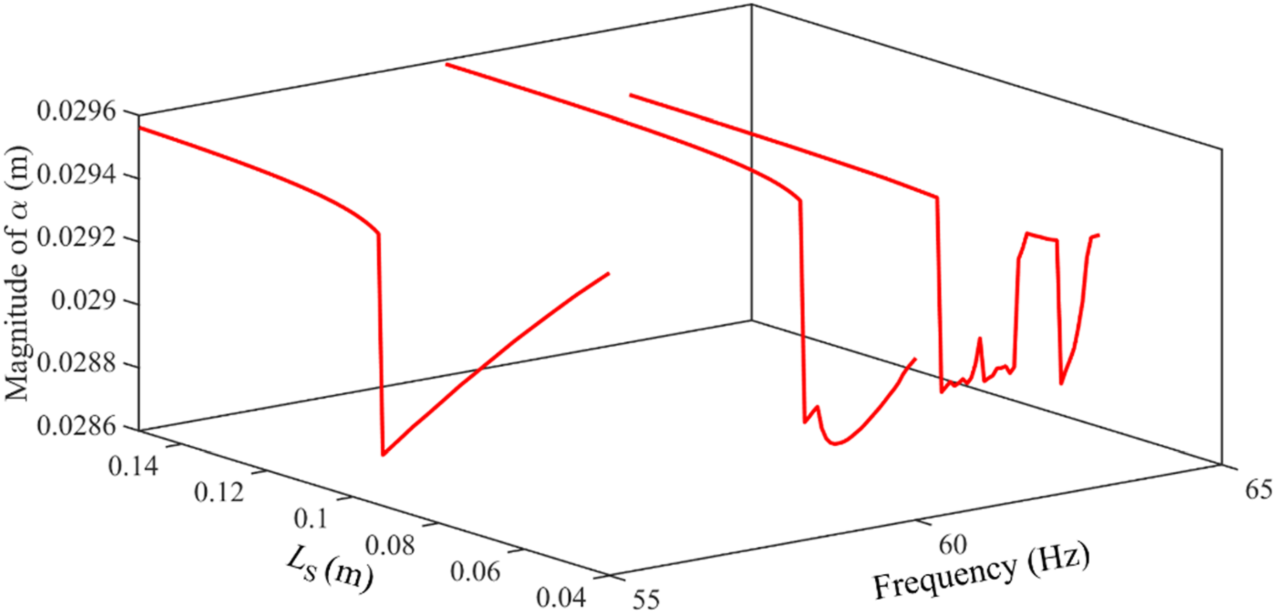
Figure 12 presents the vibration kinetic energy responses subjected to single-frequency excitation, with excitation frequencies of 55 Hz, 60 Hz, and 63 Hz. From Figure 12, for the single-frequency excitation, the vibration kinetic energy can also be significantly impacted by changing the installation length of the internal adjustable nonlinear connector. From the perspective of vibration reduction, the continuous decrease in LS is beneficial for reducing vibration at 63 Hz. In contrast, the growth of LS is suitable for vibration reduction at 55 Hz and 60 Hz. Furthermore, the magnitudes of the vibration kinetic energy responses increase suddenly when the excitation frequencies are 55 Hz and 60 Hz. From the perspective of vibration states, complex dynamic behavior emerges in vibration kinetic energy responses under specific excitation frequencies. For the excitation frequency of 55 Hz, vibration kinetic energy responses remain in a single-periodic state throughout the entire calculation domain. For the excitation frequency 60 Hz, with the decrease of LS, a region characterized by a succession of continuous amplitudes begins to emerge within the responses of vibrational kinetic energy gradually. The explanation for the above phenomena is that 60 Hz is near the 4th primary resonance area of the double-beam system. According to the analysis in Section 3.2, decreasing the installation length of the internal adjustable nonlinear connector will transfer the 4th primary resonance area to a higher frequency area. Therefore, in the decreasing process of LS, the 4th primary resonance area gradually approaches 60 Hz. At this time, magnitudes of the vibration kinetic energy and nonlinear force increase considerably, which motivates the complex dynamic behavior shown in Figure 12(b). For the excitation frequency of 63 Hz, with a decrease in LS, two regions characterized by a succession of continuous amplitudes gradually appear in the vibration kinetic energy responses. The explanation for the above phenomenon is that 63 Hz is in the middle of the 4th primary resonance area and the 5th primary resonance area of the double-beam system. According to the analysis in Section 3.2, decreasing the installation length of the internal adjustable nonlinear connector will expand the width of the region characterized by a succession of continuous amplitudes. Therefore, in the decreasing process of LS, the width of the 5th primary resonance area gradually contains 63 Hz, causing the appearance of the first region characterized by a succession of continuous amplitudes. Furthermore, similar to the analysis related to Figure 12(b), during the continuously decreasing process of LS, the 4th primary resonance area gradually approaches 63 Hz, resulting in significantly increased amplitudes of the vibration kinetic energy and nonlinear force, which causes the appearance of the second region characterized by a succession of continuous amplitudes. From the above analysis, it can be deduced that the control effectiveness of the internal adjustable nonlinear connector for vibration kinetic energy responses varies with different excitation frequencies, suggesting that the working area of the internal adjustable nonlinear connector should be set reasonably for different excitation frequencies. Furthermore, Figure 13 gives the magnitude of ɑ belonging to the double-beam system coupled through an internal adjustable nonlinear connector, where the parameters of the double-beam system correspond to those used in Figure 12. From Figure 13, the magnitude of α is greater than zero throughout the entire frequency calculation domain, verifying the validity of the numerical results shown in Figure 12. Vibration kinetic energy responses under a single-frequency excitation. Magnitude of ɑ in the calculating frequency domain.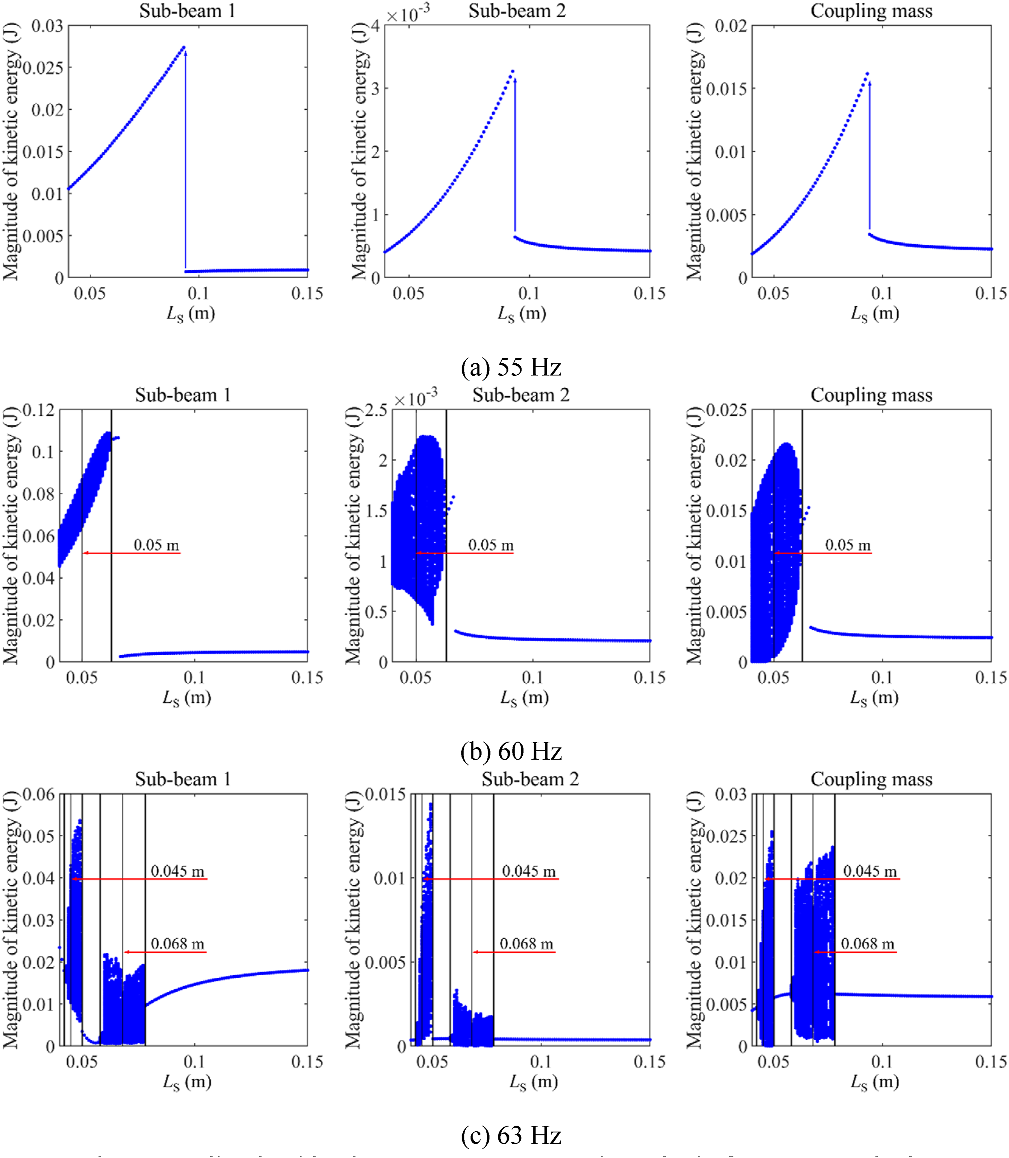
Conclusion
This work proposes a theoretical model for the internal adjustable nonlinear connector which is used to couple the double-beam system. The equivalent force function of the internal adjustable nonlinear connector is derived. On this basis, the forced vibration analysis model of the double-beam system coupled through the internal adjustable nonlinear connector is built, in which GTM is employed to calculate the vibration kinetic energy responses for the double-beam system. In numerical results and discussion, the validation of the double-beam system coupled through the internal adjustable nonlinear connector is first studied. Then, the impact of the internal adjustable nonlinear connector on vibration kinetic energy responses is discussed. The adjustable coupling nonlinear connector gives the theoretical basis for the engineering application of the adjustable nonlinearities. It is worth noting that this work primarily focuses on theoretical research. In the future, experimental research should be carried out on adjustable nonlinear devices to enhance their engineering application value. For the structural parameters of the double-beam system selected in this work, the resulting conclusions are outlined as follows. (1) Vibration kinetic energy responses of the double-beam system coupled through the internal adjustable nonlinear connector can be validly calculated by the GTM. Furthermore, it determines the effective working region of the internal adjustable nonlinear connector. Namely, the displacement of the internal adjustable nonlinear connector should be less than 0.2 times the installation length of the working springs. (2) For vibration kinetic energy responses with the change of frequency, intricate dynamic behavior of the double-beam system appears under specific installation lengths of the internal adjustable nonlinear connector. The vibration energy transfer characteristic of the quasi-periodic state is targeted energy transfer. (3) For vibration kinetic energy responses under a single-frequency excitation, the control effectiveness of the internal adjustable nonlinear connector for vibration kinetic energy responses presents differences for different excitation frequencies. The working area of the internal adjustable nonlinear connector should be set reasonably for various excitation frequencies. (4) The magnitudes of the vibrational kinetic energy responses, observed in both frequency responses and single-frequency responses, can be efficiently manipulated through adjustments to the installation length of the internal adjustable nonlinear connector. This offers theoretical support for the implementation of semi-active vibration control strategies in the double-beam system using the adjustable nonlinear connector.
Footnotes
Funding
The author(s) disclosed receipt of the following financial support for the research, authorship, and/or publication of this article: this work is supported by the National Natural Science Foundation of China (No. 52401364), the Natural Science Research Project of Higher Education Institutions of Guizhou Provincial Department of Education (Youth Science and Technology Talent Development Program, Qianjiaoji [2024]30), the Guizhou Provincial Basic Research Program (Natural Science) Youth Guidance Project (Qiankehe Basic-[2024] Youth 168), and the Fund of Natural Science Special (Special Post) Research Foundation of Guizhou University (Grant No. 2023-060).
Declaration of conflicting interests
The author(s) declared no potential conflicts of interest with respect to the research, authorship, and/or publication of this article.
Data Availability Statement
The datasets and materials generated during and/or analyzed during the current study are available from the corresponding and first authors upon reasonable request.