
Abstract
In this study, we study the application of nonlinear energy sinks (NES) for targeted vibration energy transfer and absorption in aero-engine casings subjected to shock loads. A simplified single-degree-of-freedom model with an attached NES is characterized to understand the influence of control parameters such as damping and nonlinear stiffness on the NES. Using the complexification-averaging (CX-A) technique, we analyze the main dynamic characteristics of the vibration system, revealing nonlinear normal modes (NNM) and the energy localization phenomenon that enables targeted energy transfer. Then we establish a thin-walled casing model with an NES and calculate its vibration energy transfer under shock load. The results of this study are as follows: (1) NNMs are related to initial energy, with energy localization leading to targeted vibration energy transfer and dissipation; (2) NES operates optimally within a specific energy domain, exceeding this domain reduces its effectiveness, which is primarily influenced by the NES’s nonlinear stiffness; (3) Optimizing the NES’s nonlinear stiffness on the thin-walled casing achieves targeted shock energy transfer and dissipation, significantly reducing the casing’s vibration amplitude (from 0.008 m to 0.003 m, a 62.5% reduction) and stabilization time (from 0.007s to 0.002s, a 71% reduction). The study’s results are instructive for achieving rapid stabilization of aero-engine casings under shock excitation, providing insights into the mechanism of NES and the impact of damping and nonlinear stiffness on its performance. This research guides the optimized design of NES for thin-walled casings to effectively dissipate shock-induced vibrations.
Keywords
Introduction
With the progress of modern aero-engine technology, the design concept of high thrust-weight ratio and lightweight has been gradually confirmed. Under the guidance of this design concept, the thin-walled casing structure has been widely adopted. Therefore, when the aero-engine casing is subjected to shock loads during the operation of an aero-engine, its stable state is destroyed, thus affecting the normal operation of the engine. Therefore, it is necessary to design a structure that can fast absorb the vibration energy of the magazine to stabilize it rapidly.
The nonlinear energy sink (NES) is a novel and highly efficient passive nonlinear power absorber. Compared to traditional dynamic absorbers, the NES has the advantage of fast targeted absorption of vibration energy and better robustness. In recent years, research on NES has been more extensive and has yielded rich results.1–5 Some of these scholars have applied them to the field of aero-engine and have made great progress. Borso et al 6 investigated the optimal design of several parallel NES, obtaining greater average efficiencies; Da et al 7 found that cylindrical vortex-excited vibrations can be effectively suppressed with appropriate nonlinear energy trap parameters; Q et al 8 applied the cubic nonlinearity contained in conical springs to NES, and it was found that such springs do not introduce new linear stiffness; Xe et al 9 investigated the nonlinear behavior and damping of linear systems with NES and found that linear systems with NES can achieve large damping even under simple harmonic and random excitation. Geng et al 10 analyzed the recent developments in the application of NES and proposed research directions for the dynamic design of NES structural parameters, providing significant support for the engineering application of NES. Zeng at el 11 proposed a stable state adjustable NES (SA-NES) structure, and through numerical calculations and experiments, they demonstrated its effectiveness in suppressing vibrations under different excitation intensities. However, the existing research mainly focuses on the simplified discrete model of single-degree-of-freedom or two-degree-of-freedom hair, and there is insufficient research on the vibration suppression of continuous system by NES, especially in the field of aero-engine, and there is insufficient research on the vibration suppression and fast stabilization of thin-walled casing subjected to shock load by NES, which is investigated in this paper.
Targeted energy transfer (TET) is a unique energy transfer method of NES, which is characterized by high-energy transfer efficiency and strong robustness. 12 Within a certain range of parameters, the TET is excited, and the NES oscillator can fast absorb and dissipate the energy from the primary structure. 13 In this paper, we firstly establish a two-degree-of-freedom nonlinear system and analyze its nonlinear modes and slow-variable power flow. Nonlinear modes are fundamentally different from linear modes. Rosenberg 14 first defined the concept of nonlinear norm modes (NNM) in 1960s, and then numerous scholars have investigated it and obtained rich conclusions.15–19 We have investigated the slow-variable power flow of the system by means of complexification-averaging (CX-A), which is a powerful tool for studying nonlinear systems. Manevitch et al 20 used CX-A to find that a semi-infinite chained system is capable of unidirectional, irreversible energy transfer to coupled nonlinear oscillators; Manevitch et al 21 proposed a new method to analyze the energy transfer problem between the NES and the primary system by combining CX-A and the Raschel transform, and the results suffer from some errors due to the accuracy problem of the Tayor expansion; Gendelman et al22,23 proved by CX-A that the system produces a proposed periodic response under external force, possesses better vibration damping effect, and deduced the range of stiffness; Zhang et al 24 introduced inertial capacity in NES to improve the vibration damping performance of the system, used CX-A to analyze the coupled system to derive the periodic solution, and used the analytical solution to perform bifurcation studies; Li et al 25 proposed a new optimization method to enhance the vibration suppression performance by considering the nonlinear factors in the vibration process of a linear absorber and using CX-A and multiscale method to obtain the relationship between frequency and energy; Zhang et al 26 derived a mass ratio interval for the occurrence of stress braking response, and better damping effect and robustness were obtained by taking the midpoint of the interval as the optimum mass ratio.
Aiming at the axial symmetry characteristics of the thin-walled casing structure, this paper establishes a 1/4 cylindrical thin-shell model with a rigid body impacting at a certain speed with an NES structure connected. The vibration suppression effect and fast stabilizing effect of NES on the thin-shell model structure under impact are analyzed, and the influence law of different NES parameters on the behavior of NES is calculated.
In summary, in this study, the phenomena of internal resonance and energy localization of the nonlinear system are investigated firstly by carrying out the study of the mass model connecting the NES and analyzing its nonlinear modes and frequency-energy correspondence; and the slow-variable power flow of this system is analyzed by using the CX-A technical, and then the application conditions of the NES and the influence laws of the control parameters (stiffness and damping of the NES) on the NES are analyzed by numerical calculations. Then the model of the curved shell with NES attached and subjected to impact load is constructed, and with the laws obtained from the single-mass model as a guide, the absorption of vibration energy by NES is calculated by displaying the dynamics, and the fast stabilization of the curved shell structure under impact load is achieved by optimizing the structural parameters of NES. The research in this paper has some guiding significance for the rapid stabilization of aero-engine magazine structure under impact load.
Analytical models: from real casing model to the two-pointed thin-shell structure
Firstly, we have provided the structural form of the NES as shown in Figure 1. The structural form of the NES.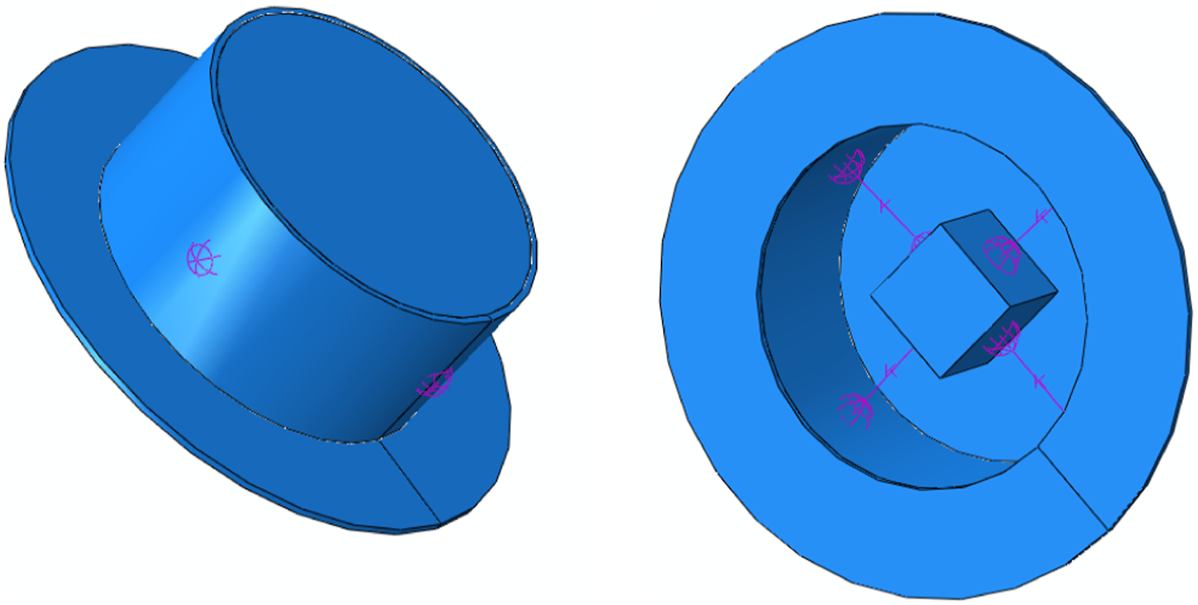
In the NES structure depicted in Figure 1, it mainly comprises a cylindrical outer casing, a central mass block, and four linear springs connecting the two.
We initially presented a schematic force diagram of the NES, as shown Figure 2. The force diagram of a NES.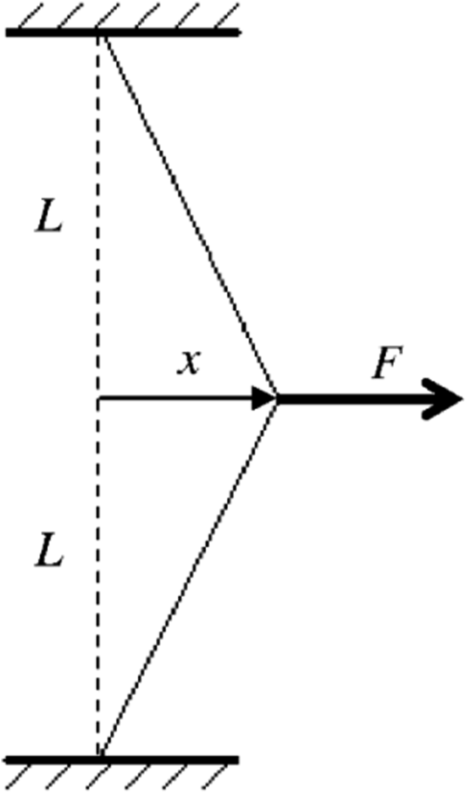
In the initial stage of our analysis, we conducted a force analysis on Figure 2, which led to the derivation of equation (2.1).

By performing a Taylor expansion on equation (2.1) and simplifying, we can obtain equation (2.2).

Ignoring the higher-order terms in equation (2.2), we can derive equation (2.3).

For the structure shown in Figure 1, which has two pairs of linear springs, the relationship between the displacement of its mass block and the force is as described in equation (2.4).

Therefore, the nonlinear stiffness of the NES structure shown in Figure 1 is directly proportional to the stiffness of the linear springs and inversely proportional to the distance between the mass block and the external cylindrical casing. Additionally, the damping of the NES can be achieved by filling rubber material between the mass block and the external cylindrical casing. During the process of numerical computation, it can be simplified to a mass-point structure with nonlinear stiffness.
Subsequently, we analyze the model of the aero-engine casing and its simplification treatment. This analysis involves understanding the structural dynamics of the casing, identifying its critical components, and determining how these can be effectively represented in a simplified model that captures the essential behavior for the study of the NES’s impact on the system.
The physical model aimed at in this study is the structure of the aero-engine casing, as shown in Figure 3. As can be seen from Figure 3, the structure of the real aero-engine casing is very complex, and it will take a lot of time to directly analyze its real model. Moreover, because the model itself contains many nonlinear factors, it is difficult to extract important data from the calculation results for analyzing the influence of NES on structural vibration. Therefore, it is necessary to reasonably simplify the actual casing structure, ignore the secondary factors such as flanges and mounting holes on the casing, and retain the main part of the casing. The casing can be regarded as a thin-walled cylindrical shell structure.
27
Further, because the thin-walled cylindrical shell has good axisymmetric properties, it can be simplified to a 1/4 cylindrical shell, as shown in Figure 4, further simplifying the calculation model, but retaining its important structural properties. Aero-engine casing structure. Thin-shelled model.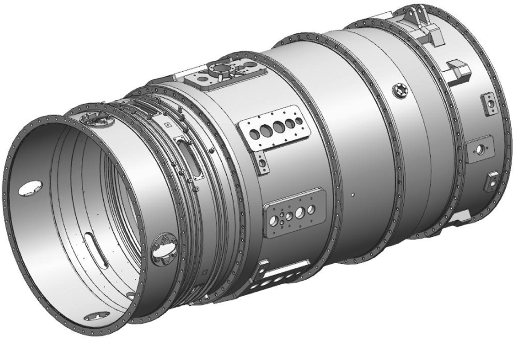
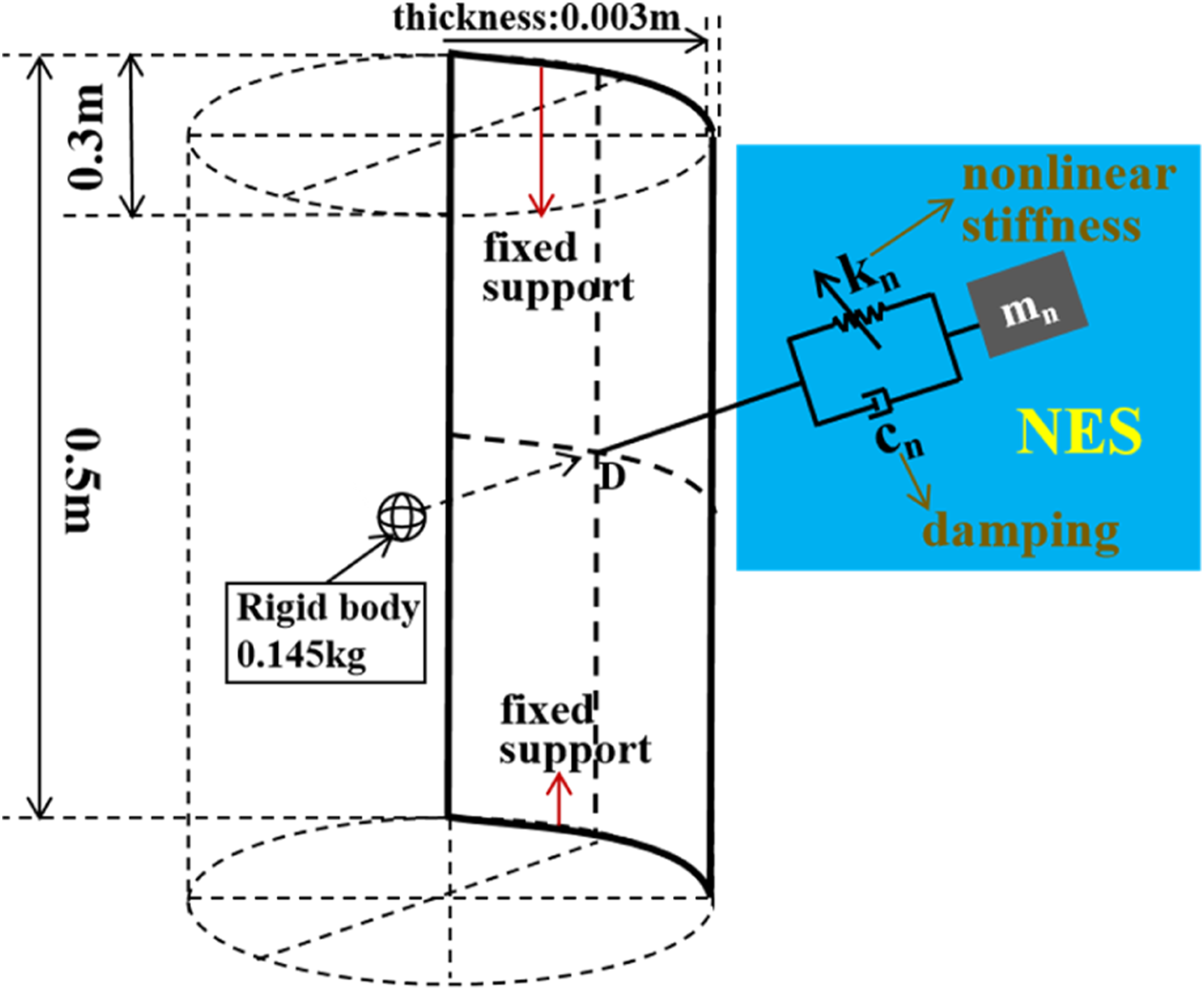
In Figure 4, (a) rigid mass impacting the thin-walled shell structure is also provided to simulate the impact action, and an NES connected to the thin-walled shell with cubic stiffness is used to absorb the thin-shell vibration caused by the rigid body impact. As depicted in Figure 4, the nonlinear stiffness is represented by diagonal arrows, and the blue shaded area indicates the NES.
The model is in the form of a fixed support with opposite sides, the elastic modulus of the material is 200 GPa, Poisson’s ratio is 0.3, the density is 8240 kg/m³, and the damping of the material is set to be in the form of proportional damping with α = 0.1 and β = 5 × 10⁻⁶.
Firstly, due to the minimal mass we assigned to the NES, its impact on the dynamic performance of the primary structure is negligible, ensuring that it does not interfere with the normal operation of the original structure. Secondly, in all the derivations and calculations presented in this paper, it is only necessary to obtain the elastic modulus, Poisson’s ratio, and density of the casing material, and to ensure that the casing structure is sufficiently thin to meet the characteristics of thin-walled materials.
In the model of this study, the impact load on the magazine is simulated by setting the behavior of a rigid body colliding with the magazine, and the location of the collision between the rigid body and the magazine is noted as point D. The impact energy of the magazine is changed by setting the velocity of the rigid body. At the same time, a cubic stiffness NES device is attached at the location where the magazine is subjected to impact (point D) to study the role of NES in absorbing vibration energy and stabilizing the magazine quickly. The stiffness coefficient of the NES is kn, the damping coefficient is cn, and the mass is mn. In engineering practice, the added mass needs to be much smaller than the mass of the main system in order not to affect the structural performance of the main system, so mn is set to be 5% of the mass of the 1/4 shell structure (0.145 kg).
For the thin-walled shell structure shown in Figure 4, the vibration suppression effect of NES on it can be calculated under a single condition. However, for the parameter optimization calculation of NES and the exploration of the vibration suppression law of NES, the calculation generally needs to be carried out under a large number of different parameter conditions, and the time cost is still extremely high, which is unacceptable (Based on ABAQUS software, one calculation takes about 5 min, while the optimization calculation process typically requires tens of thousands of calculations and more than 800 h of calculation time). Therefore, in this study, it was decided to first analyze the vibration suppression of single-degree-of-freedom mass by NES, as shown in Figure 5, to find the application law of NES, which can be used to guide the design of NES on thin shells, thus saving a lot of time and cost. Two-pointed structure.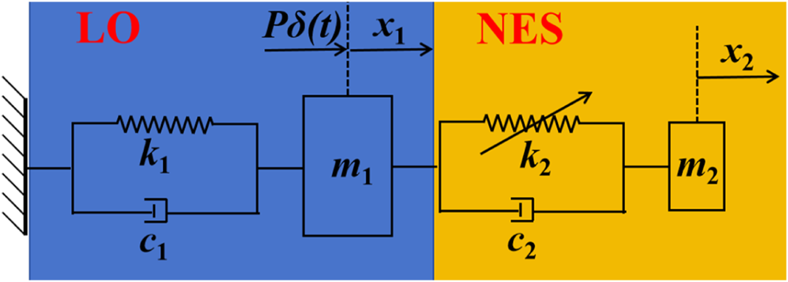
In Figure 5, the shock excitation of the thin-walled shell structure is simulated by applying a transient excitation to a linear oscillator (LO) connected to the ground through linear stiffness and damping. The NES is connected to the LO through cubic stiffness and linear damping.
The working mechanism of NES is studied through this simplest system and the working range of NES is analyzed with the variation of its parameters.
Dynamic analysis of the two-mass structure
This section analyzes the working mechanism and laws of NES based on the model in Figure 5. The system is analyzed through three aspects: nonlinear norm mode, slow-variable power flow characteristics, and vibration response characteristics under different excitations. In order to provide support for the optimized design of NES parameters mounted on a thin shell.
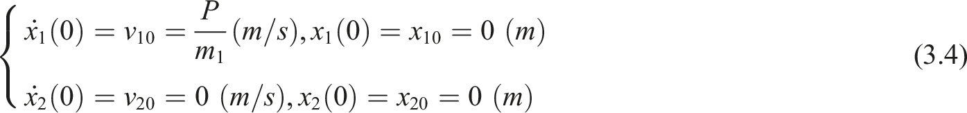
To carry out an in-depth study of the dynamical characteristics of this system, the study is carried out in both theoretical analysis and numerical computational structure. For this purpose, the governing equations of the system, shown in Figure 5, are first written for theoretical analysis as shown in equation (3.1).

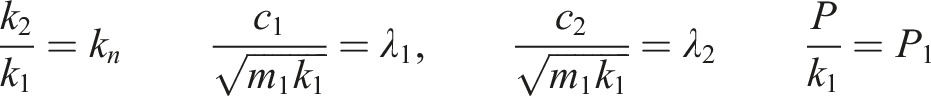
To simplify the complexity of the derivation process, the above equations are subjected to variable substitution and normalization, and the parameters shown in equation (3.2) are brought into equation (3.1) to obtain equation (3.3), while


For this control equation, this paper carries out the study of nonlinear norm modal analysis, slow-variable power flow analysis, and NES application mechanism, respectively.
Nonlinear norm modal analysis
In this subsection, a nonlinear modal analysis is carried out for the two-mass structure shown in Figure 5. Neglecting the damping and external excitation of equation (3.3) and (3.5) is obtained.

Since the amplitude, frequency, and phase of the system response are mainly concerned in engineering, it is analyzed qualitatively based on trigonometric functions. Moreover, the vibrational energy transfer of the system mainly occurs when the system produces a 1:1 internal resonance, so the dynamical response is analyzed when the LO and NES have the same frequency. Assume that the displacement expressions for LO and NES are shown in equation (3.6).


Analyzing the second equation of equation (3.7) yields equation (3.8).


The analysis of equation (3.9) reveals that when the vibration frequency is close to the due frequency of LO, the system energy will be mainly concentrated toward NES, and in addition, when the vibration frequency is from less than one to more than 1, the amplitude ratio is flipped, that is, it is changed from in-phase vibration to out-of-phase vibration.
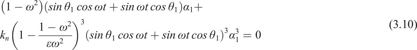
Then, by bringing equation (3.6) and (3.8) into the first equation of equation (3.7) and performing the Euler transformation, equation (3.10) can be obtained.
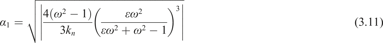
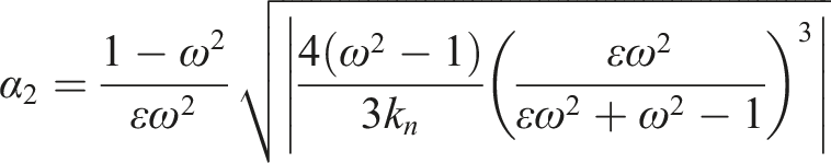
The integral of equation (3.10) multiplied by the cosine term in one cycle, with appropriate transformations, and combined with equation (3.9) leads to equation (3.11).
The system is conservative and its mechanical energy expression is shown in equation (3.11).

Combining equation(3.12) and (3.11), the relationship between the system vibration frequency and the vibration energy (frequency–energy diagram) was calculated and plotted, and the configuration space curves of the system under different vibration frequencies and energy conditions were identified in the diagram, as shown in Figure 6. Frequency–energy diagram for the two-mass structure.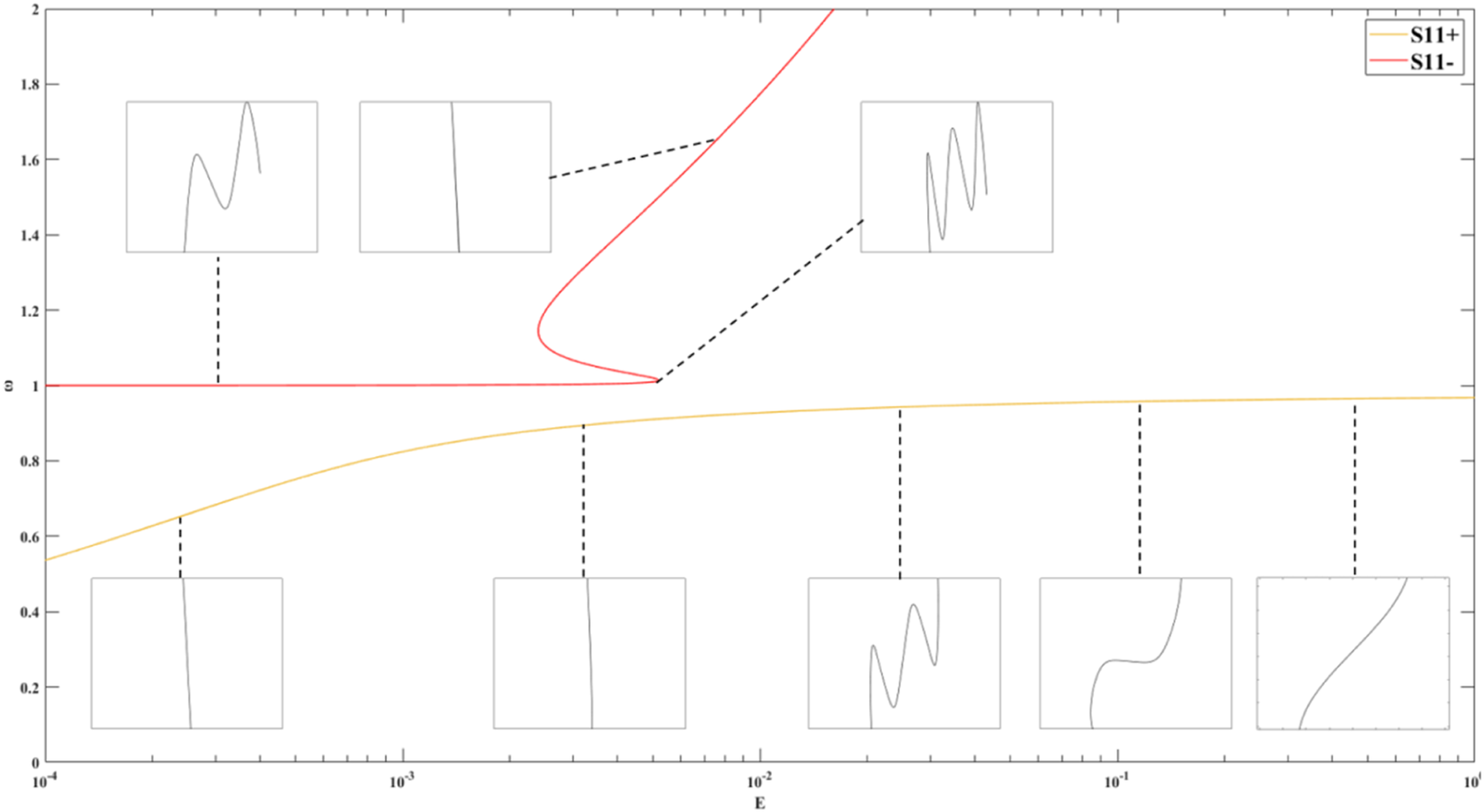
From Figure 6, it can be seen that for the in-phase vibration (S11+ branch), in the low-energy state, the vibration energy of the system is mainly concentrated on the NES, and the vibration amplitude of the LO is small, and with the gradual increase of energy, the vibration energy is gradually transferred from the NES to the LO, and loses the state of energy localization. For the out-of-phase vibration (S11-), with the increase of vibration energy, the vibration energy is gradually gathered on the NES, and the vibration gradually becomes a standard 1:1 internal resonance.
Therefore, the intrinsic mechanism of targeted energy transfer in nonlinear systems is nonlinear vibration modes and vibration energy localization, and in order to realize the targeted absorption of vibration energy by NES, it is necessary to make the system in appropriate vibration modes to promote vibration energy localization at the NES position.
In order to further analyze the dynamics of the nonlinear system with damping, the CX-A technical is introduced to analyze the slow-variable power flow properties of the vibrating system.
Slowly varying power flow analysis
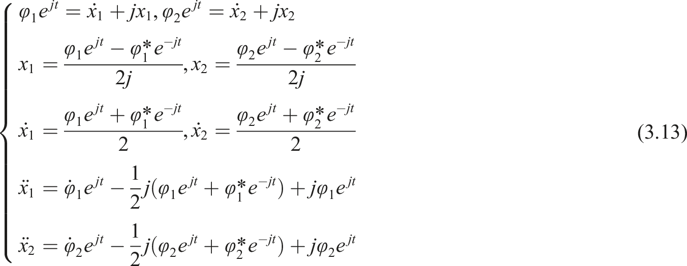
In this subsection, the slow-variable power flow of the system is analyzed by introducing the CX-A. The variable substitution shown in equation (3.13) is first introduced.
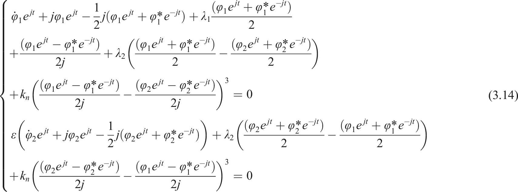
Bringing equation (3.13) into equation (3.3) leads to equation (3.14).
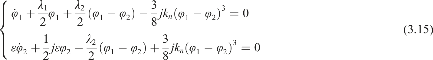
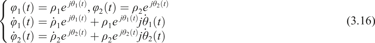
Bringing equation (3.16) into equation (3.15) yields equation (3.17).
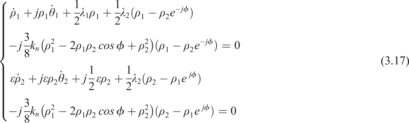
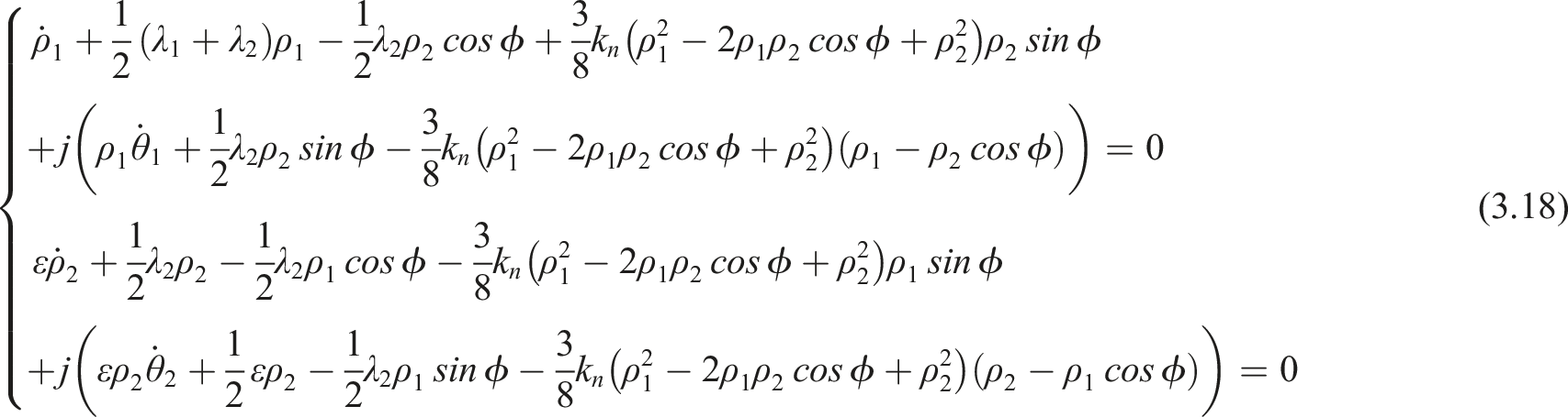
Applying Euler’s theorem to equation (3.17) and separating the real and imaginary parts leads to equation (3.18).
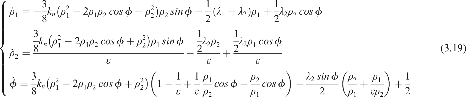
Organizing equation (3.18) yields the slow-variable power flow equations for the system, as shown in equation (3.19).
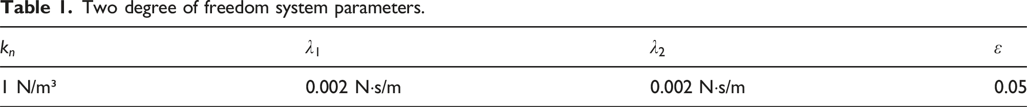
Two degree of freedom system parameters.
Initial parameters.
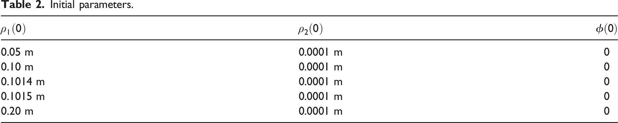
The results of the calculations for the 5 initial parameters in Table 2 are shown in Figure 7. Response results for slowly varying power flow systems. From top to bottom are the results for ρ1 (0) equal to 0.05.0.10.0.1014.0.1015.0.20; from left to right are the results for the displacement of the LO and NES, the results for the phase difference, and the configuration space curves, respectively.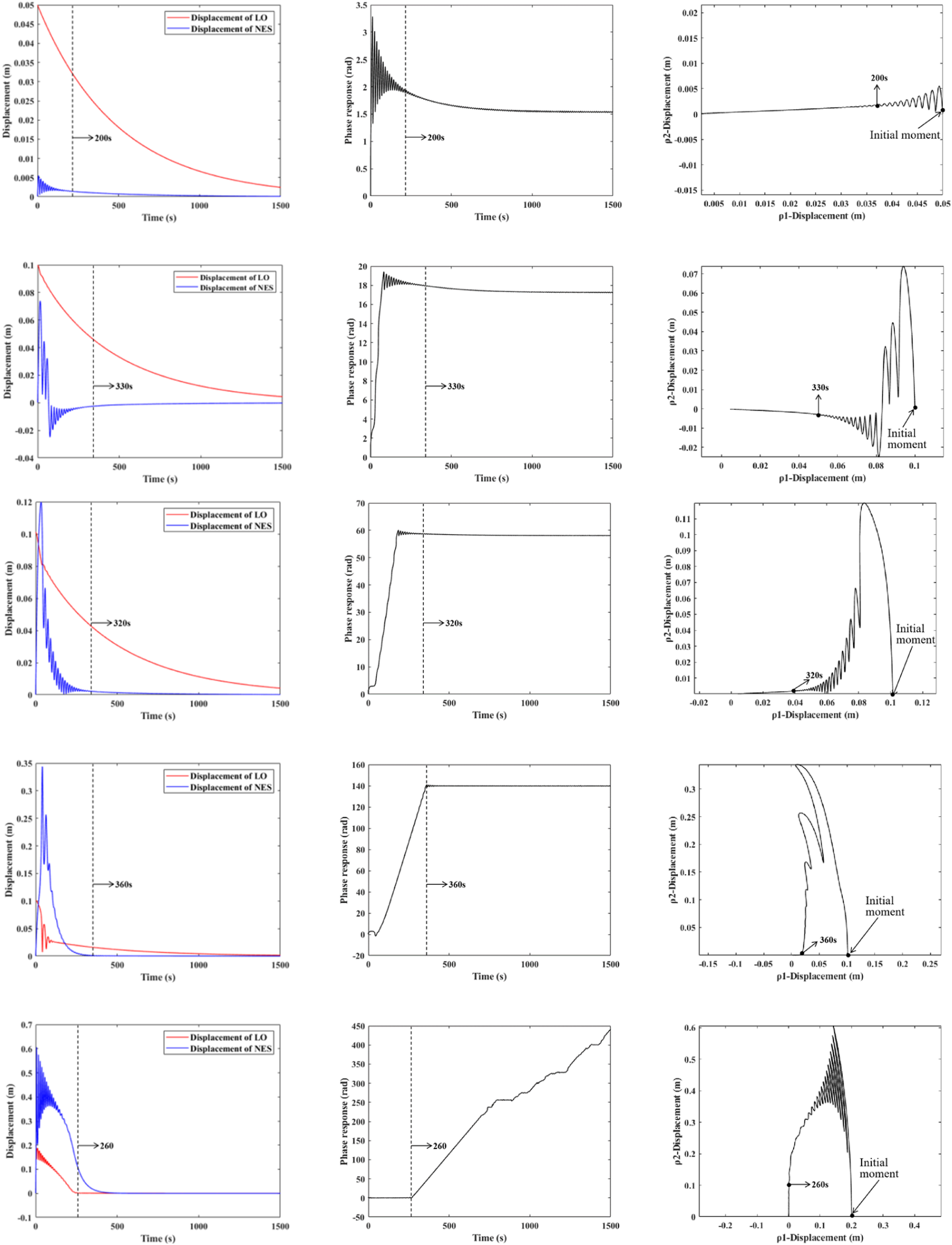
As can be seen in Figure 7, in the low-energy conditions (0.05, 0.10, 0.1014), the vibration of the system is mainly concentrated on LO, and the NES dissipates less energy, and it can be seen from the configuration space curves that the vibration curve of the system becomes transverse, that is, the NES tends to be stationary, and it is mainly LO that vibrates, after the initial excitation. In the high-energy condition (0.1015, 0.20), the vibration of the system is mainly concentrated on the NES, and it can be seen from the bit pattern space that the vibration curve of the system is overall longitudinal (mainly the NES is vibrating). Therefore, it can be seen that for nonlinear systems with damping, the NES only works when the excitation exceeds a certain level, that is, the NES has an initiation threshold. In addition, by comparing the results for ρ1 (0) of 0.1014 and ρ1 (0) of 0.1015, it can be found that the dynamical state of the system changes very drastically near the startup threshold of NES. Further comparing and analyzing the results of LO vibration under five initial conditions, it can be found that despite the larger initial displacement, the LO vibrator reaches the stable state the fastest at ρ1 (0) of 0.20, and the goal of fast stabilization is achieved. Analyzing the results of phase difference and the results of bitmap space curve, it can be found that before 260s, LO and NES are in the state of 1:1 resonance (the phase difference is 0), and the vibration amplitude of NES is much larger than that of LO (the curve in the bitmap space is similar to the vertical state), so the NES has dissipated a lot of vibration energy, which leads to the rapid stabilization of LO.
Through the analysis of the slow-variable power flow response of the system, it can be found that for the nonlinear system with damping, the NES has a start-up energy threshold, and when the vibrational energy exceeds this threshold, the system can realize the internal resonance state between the LO and the NES, and the NES can target the energy absorption and dissipation, thus stabilizing the LO oscillator rapidly.
In order to further analyze the influence law of different system parameters of NES on the action of NES, the dynamical response of system 3.3 under different system parameters and initial conditions is calculated by the Rongo Kuta method.
Effect of initial excitation on NES vibration suppression
In this section, the analysis is carried out for equation (3.3) to investigate the general rule of NES application. In order to analyze the dissipation of vibration energy by NES, the definition shown in equation (3.20) is done.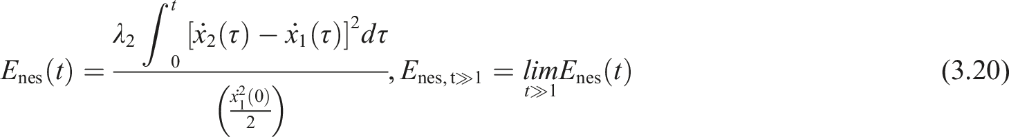
First, set λ1 = λ2 = 0.002, kn = 1, ε = 0.05. The Enes at different initial velocities are obtained by numerical calculations, and the results are shown in Figure 8. Proportion of vibration energy absorbed by NES for different initial conditions.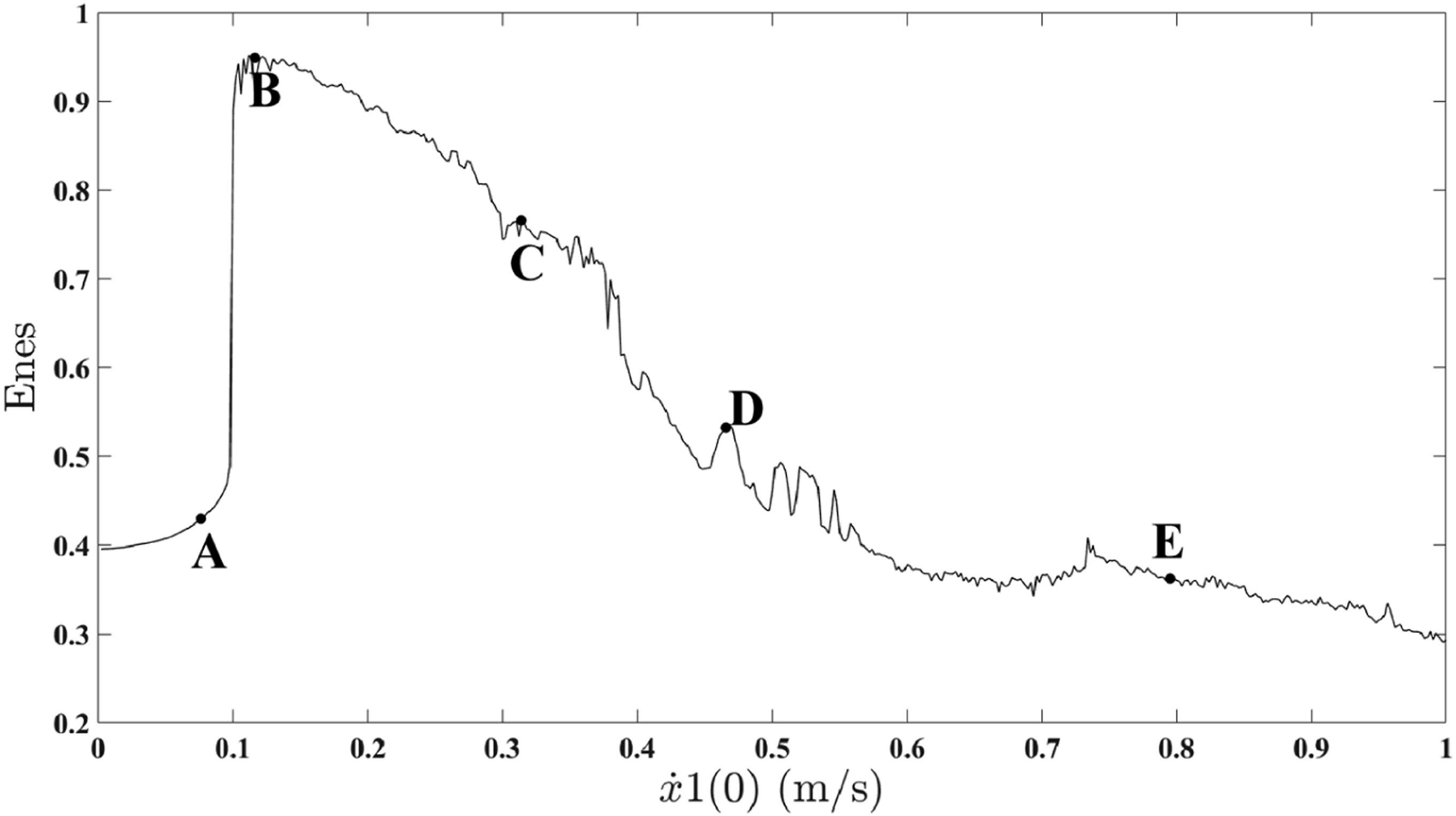
The results show that the NES absorbs the vibration energy best up to 94% (point B) under conditions of moderate initial velocity (BC segment range). In the case of too much energy (greater than E) or too little (less than A), the effect of NES is greatly reduced.
In order to further analyze the vibration characteristics of the system under different initial conditions, the dynamic responses of the system at five points A, B, C, D, and E were calculated, and the results are shown in Figure 9. Response results for a two-pointed structure. From top to bottom are the results of a, b, c, d, e; from left to right are the results of displacement response, wavelet analysis of LO response, and wavelet analysis of NES response, respectively.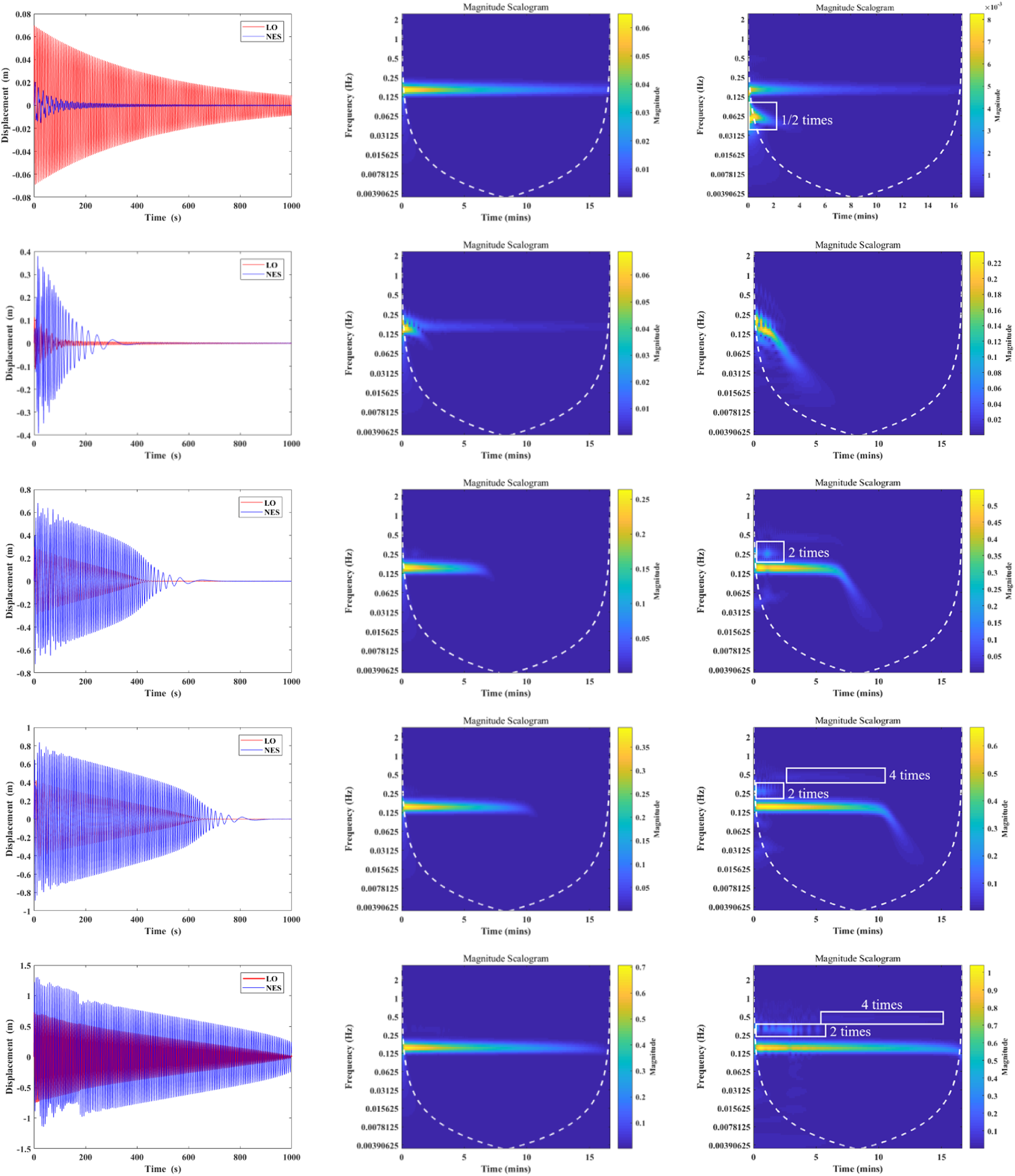
From the results in the Figure 9, when the initial excitation is small (A), the vibration of the NES is much smaller than that of the LO, that is, the vibration energy is mainly dissipated through the LO system; with the increase of the initial excitation energy (B), the LO vibration decays rapidly, and the NES continues to vibrate to dissipate the energy; when the vibration energy increases continuously (C, D, E), the LO vibration tends to be synchronized with the NES vibration, which is consistent with the state presented in the bitmap space curve of the system in Figure 4 at the high-energy state.
By comparing the wavelet transform of the LO vibration and the wavelet transform plot of the NES vibration, it can be found that when the initial excitation is small (A), there is a portion of 1/2 octave frequency in the response of the NES in addition to the portion of the response frequency that is the same as that of the LO; when the initial excitation is most appropriate (B), the response frequency of the NES at the beginning is the same as that of the LO, and when the LO is stationary, the response frequency of the NES decreases with time until the NES is stationary; when the vibrational energy is continuously increased (C, D, and E), the response frequency of the NES shows a high octave frequency response in addition to a part of the response frequency that is the same as that of the LO and is gradually obvious. Therefore, it can be found that the NES can work best when the vibration of LO and NES is exactly 1:1 resonance, and the occurrence of both sub-multiple and high-multiple frequencies affects the effectiveness of the NES.
After analysis, it can be obtained that the LO oscillator can be restored to stability in a short time under suitable initial excitation. Therefore, we can say that the NES has an optimal energy domain, and when the excitation energy exceeds the domain, the vibration suppression effect of the NES is greatly reduced.
Matching between NES optimization parameters and external excitation
In order to further analyze the transformation relationship of the domain of action of NES with respect to the parameters, the efficiency of energy absorption by NES with different cubic stiffness coefficients (damping coefficient selected to be 0.002) and different damping coefficients (cubic stiffness coefficient to be 1) is calculated.
During the computational process, the first step involves, for a NES structure with specific damping coefficients and specific nonlinear stiffness, calculating the dissipation capacity of the NES by setting different initial conditions (i.e., the vibrational energy of the system). Subsequently, the relationship between the energy dissipation capacity of the NES and the nonlinear stiffness is obtained by varying the nonlinear stiffness, and the damping coefficient is maintained at 0.002 (the same as the damping coefficient of the LO oscillator). The results of the calculations are shown in Figure 10. Plot of 3D and 2D results of the variation rule of NES action effect with nonlinear stiffness.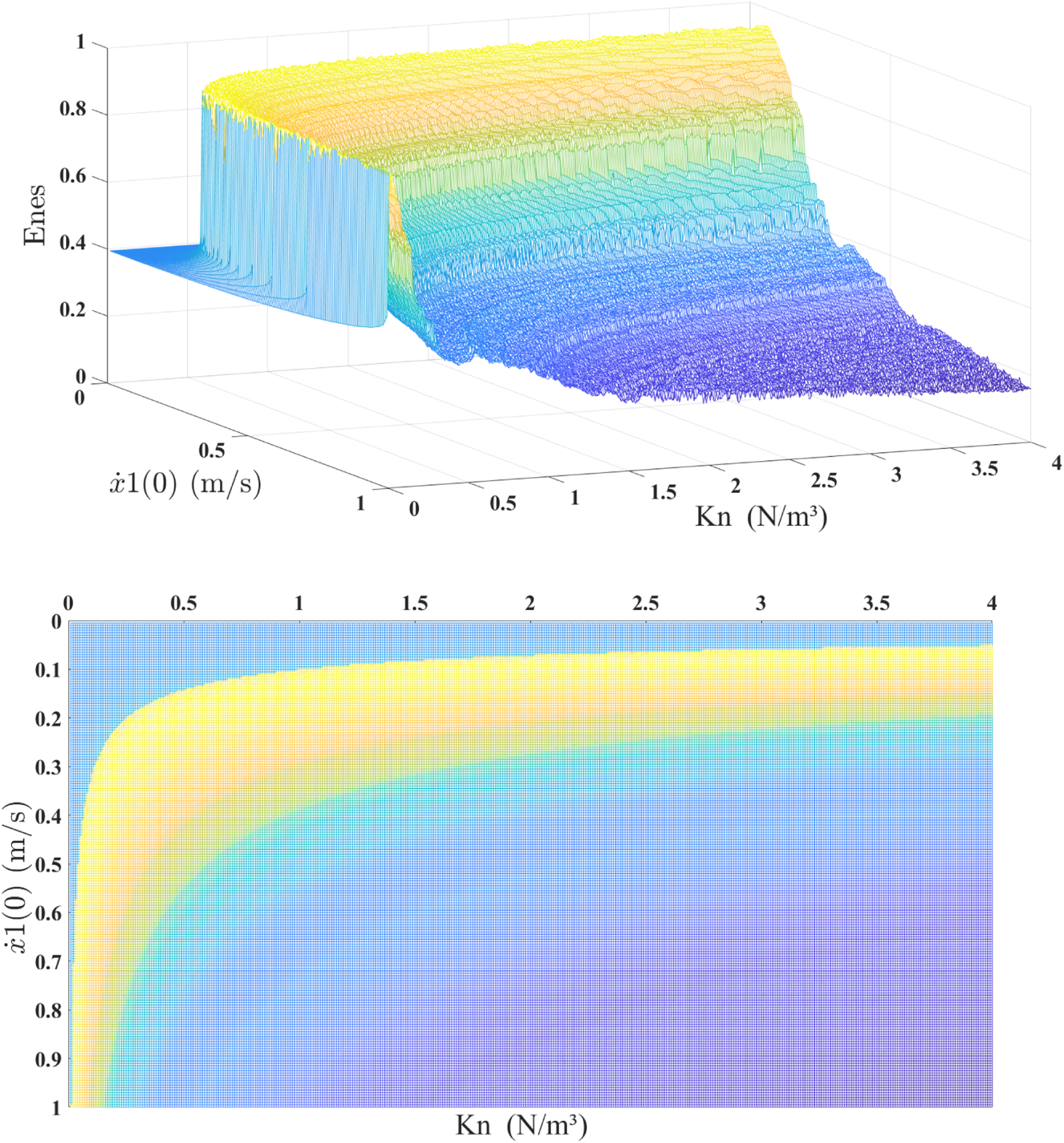
From Figure 10, it can be observed that the optimal energy action domain of the NES is related to its inherent nonlinear stiffness. As the nonlinear stiffness decreases, the value of the NES’s optimal action domain generally increases, but the range of the domain is narrowing.
To further analyze its characteristics, we define the optimal action domain of the NES as the range where the energy dissipated by the NES exceeds 80% of the total energy. Based on this, Figure 11 is drawn to illustrate the range of the optimal energy action domain, as well as the nonlinear stiffness and initial conditions corresponding to the maximum energy dissipation. The optimal energy action domain and maximum dissipation value curves of the NES.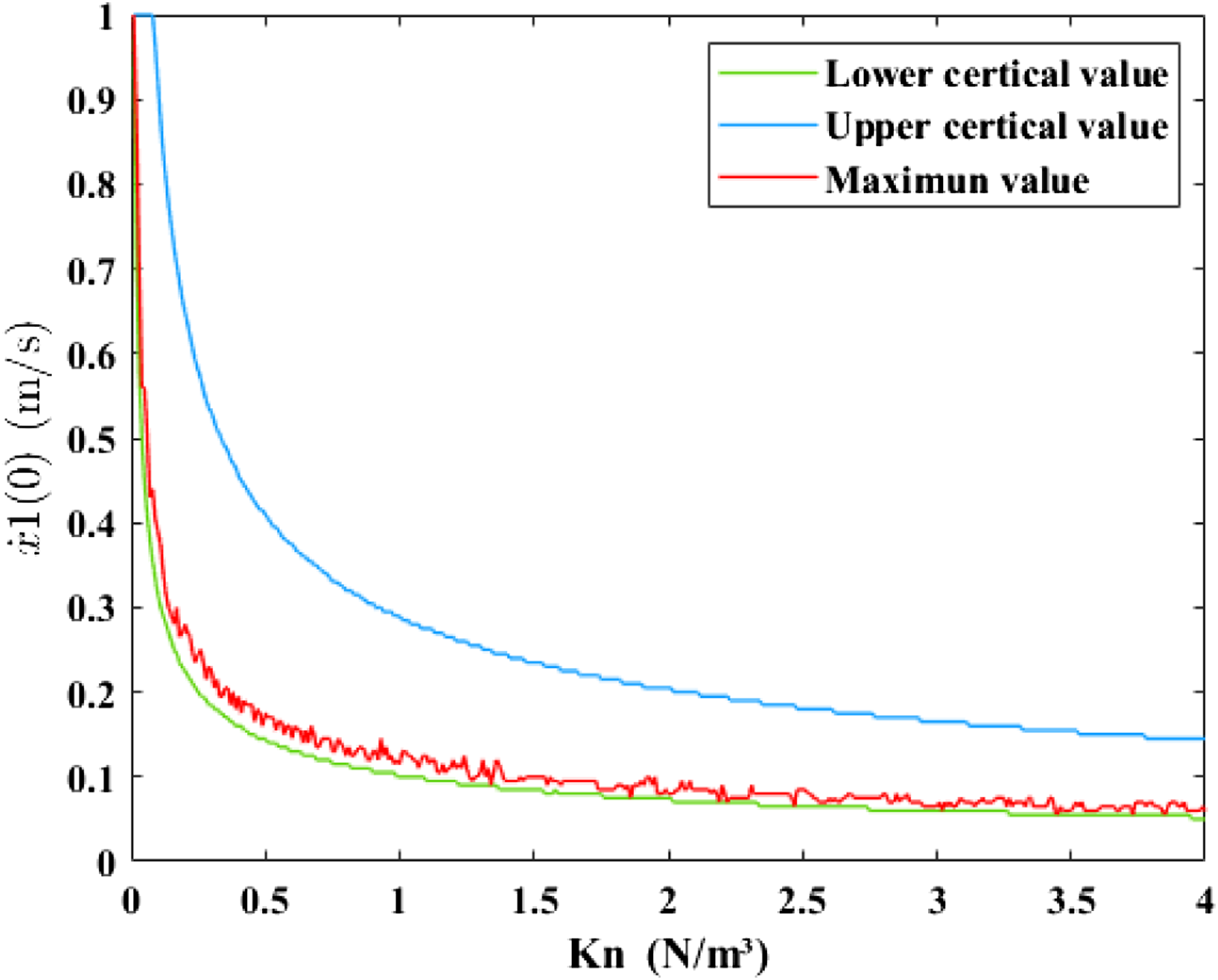
From Figure 11, it can be seen that the maximum value of energy dissipation is very close to the lower critical value of the optimal energy action domain. This indicates that within the range of the optimal energy action domain, a smaller value of nonlinear stiffness should be chosen as much as possible.
In summary, when selecting the optimal parameters for the NES under different excitations, based on the optimal nonlinear stiffness value of the NES under a certain excitation, the selection direction for the nonlinear stiffness value under other excitations can be given according to the above rule. When the impact effect increases, enhance the effectiveness of the NES by reducing the appropriate stiffness value; when the impact effect decreases, enhance the effectiveness of the NES by increasing the appropriate stiffness value.
Subsequently, the impact of damping on the optimal action domain of the NES was analyzed, and the results are shown in Figure 12. Plot of 3D and 2D results of the variation rule of NES action effect with nonlinear stiffness.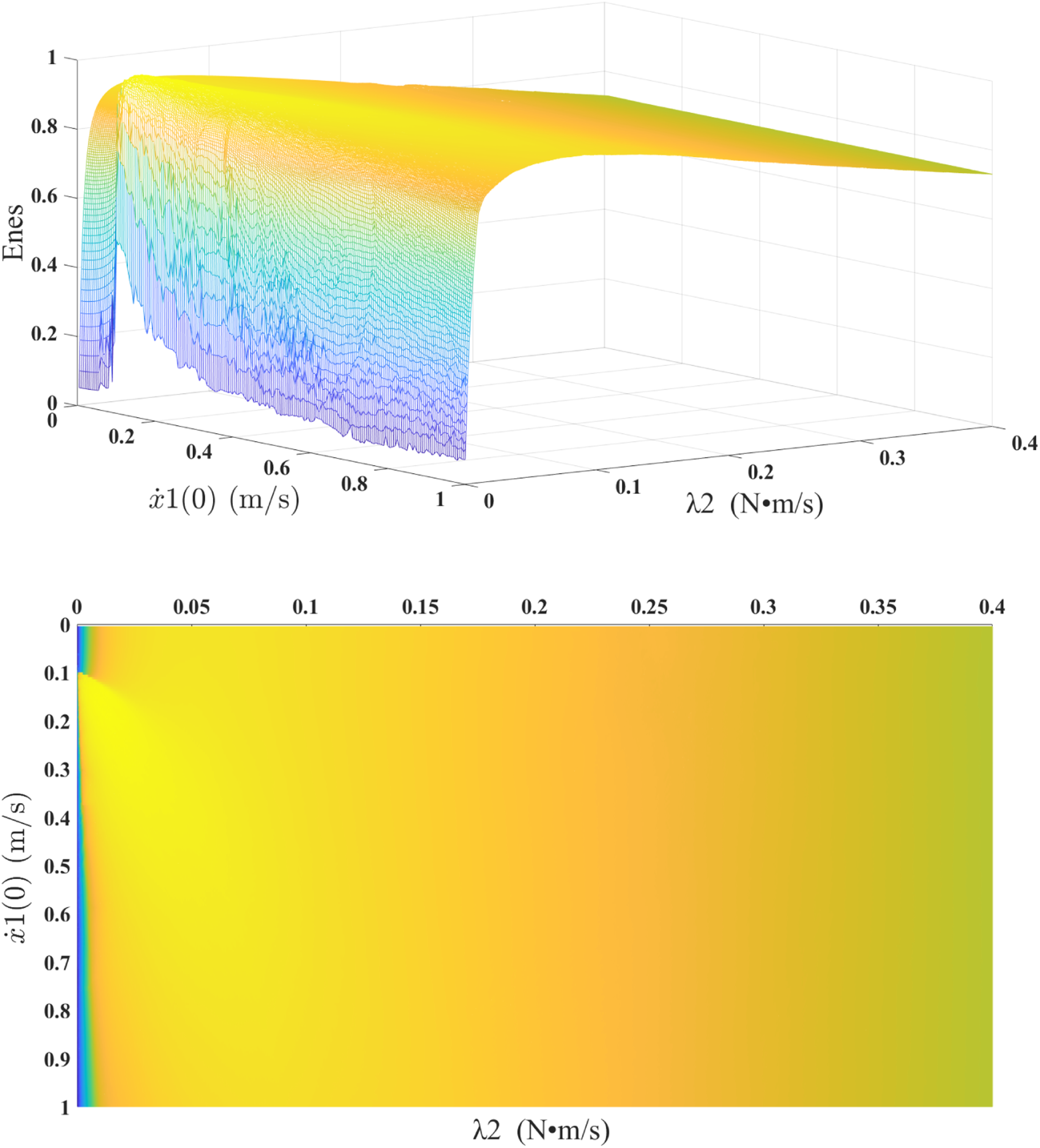
The analysis of Figure 12 shows that the damping coefficient of NES is not relevant to the domain of action of NES. However, when the damping coefficient of NES increases, the overall percentage of shock energy absorbed by NES decreases, that is, NES is more effective under weak damping conditions.
Optimization of NES parameters connected to a thin-walled shell and its vibration suppression
In this section, the previously studied NES parameters and external excitation matching law are taken as a basis to optimize the calculation of NES parameters on the thin-shell structure shown in Figure 4. And, the suppression effect of NES on thin-walled shell vibration is analyzed. The calculation and analysis are performed in terms of vibration amplitude reduction and vibration stabilization time reduction, respectively.
Similarly, the ratio of the energy dissipated by the NES to the total dissipated energy is denoted as Enes.
According to subsection 2, the mass of the NES is selected as 0.145 kg, which is not involved in the optimization process for the reasons stated in subsection 2. For the nonlinear cubic stiffness connecting the NES to the thin shell, the dissipation of vibration energy by the NES with different stiffness coefficients is first calculated for different impact excitations. Firstly, we select NES with nonlinear stiffness coefficients of 1 × 10¹¹, 5 × 10¹¹, and 1 × 10¹², and damping coefficients of 500 and 1000. The rigid body impact velocity on the casing is set from 1 m/s to 80 m/s (with an interval of 1 m/s). The calculated percentage of energy dissipated by the NES relative to the total energy is shown in Figure 13. This setup allows for an in-depth study of how varying the stiffness and damping parameters of the NES affects its energy absorption and dissipation performance under a wide range of impact velocities. Variation curves of the effect of NES action with impact velocity for different nonlinear stiffnesses. (a) Stiffness coefficient: 1 × 10¹¹ N/m³, (b) stiffness coefficient: 5 × 10¹¹ N/m³, (c) stiffness coefficient: 1 × 10¹² N/m³.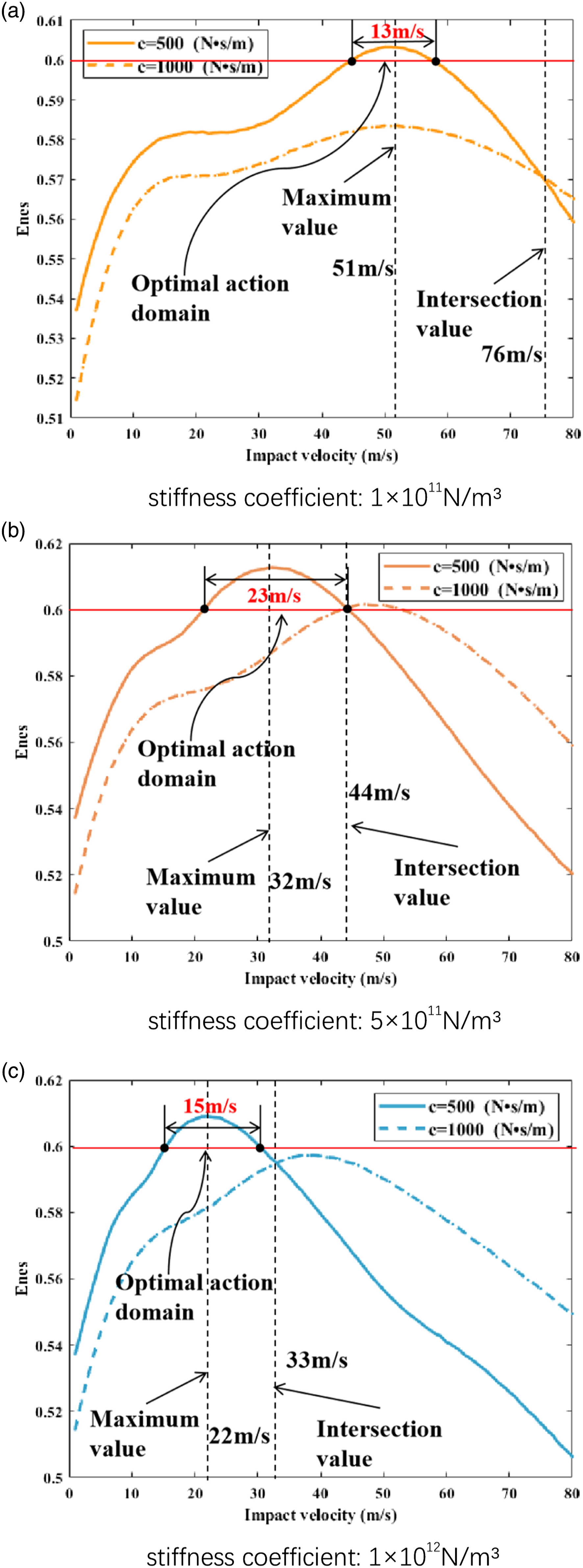
In Figure 13, the range where the NES dissipates more than 60% of the total energy is marked, representing the optimal operating range for the NES.
The analysis of Figure 13 shows that for different stiffness coefficients and damping coefficients, the NES exhibits the property of having an optimal working region, which is the same as the conclusion obtained for the two-mass structure. However, it can be observed that, with a fixed nonlinear stiffness, when the impact velocity is relatively low, the performance of a Non-Energy-Storing (NES) system with a lower damping coefficient is superior to that of a system with a higher damping coefficient. Conversely, when the impact velocity is high, the outcome is the opposite. Further analysis reveals that the NES efficiency curve with small damping coefficient has an intersection with the NES efficiency curve with large damping coefficient, and the shock velocity corresponding to this intersection decreases with the increase of the stiffness coefficient.
Based on the curve shown in Figure 13, it can be observed that as the nonlinear stiffness of the NES increases, the initial velocity of the primary structure corresponding to the conditions for maximum dissipation capacity of the NES gradually decreases. This indicates that during the operation of the NES, when the impact load on the primary structure increases, it is necessary to correspondingly reduce the nonlinear stiffness of the NES to achieve the goal of maximum absorption and dissipation of vibrational energy by the NES.
However, comparing the response curves of different stiffness coefficients and damping coefficients, it can be found that the optimal performance of NES under small damping coefficient is better than that of large damping coefficient, therefore, small damping coefficient should be selected as much as possible if it is not necessary. Therefore, when the primary structure is subjected to impacts of varying magnitudes, there is no need to alter the level of damping.
We can observe that the performance characteristics, damping, and the influence of nonlinear stiffness on the NES connected to the simplified casing model follow the same pattern as the conclusions drawn from the two-mass structure. However, unlike the results of the two-mass structure where the NES can dissipate up to 94% of the vibration energy, in the thin-shell structure, the NES can dissipate up to only about 61% of the vibration energy.
Subsequently, to enhance the credibility of our conclusions, we performed calculations for NES with nonlinear stiffness coefficients ranging from 1 × 10¹¹ to 1 × 10¹² (with an interval of 1 × 10¹¹). The results obtained are depicted in Figure 14. In Figure 14, different colors represent different nonlinear stiffness values, the solid lines indicate a damping coefficient of 500 for the NES, and the dashed lines represent a damping coefficient of 1000 for the NES. The visual representation through different colors and line styles in Figure 14 allows for a clear comparison of the energy dissipation capabilities of the NES under varying conditions, thereby reinforcing the validity of our findings. The performance of an NES with different nonlinear stiffness and damping.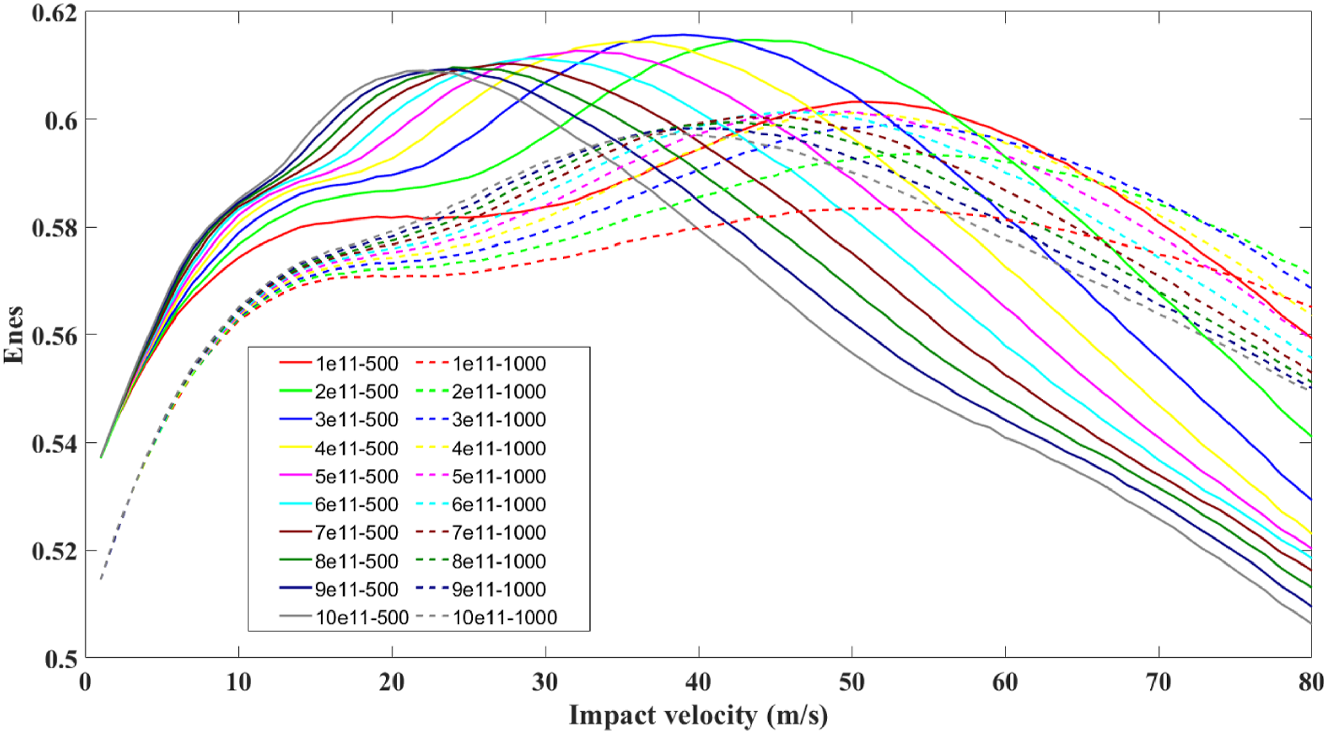
From Figure 14, it can be observed that the performance of the NES with weaker damping is generally better than that of the NES with higher damping. Additionally, as the nonlinear stiffness increases, the impact velocity corresponding to the optimal performance of the NES decreases accordingly. This observation confirms the validity of the aforementioned conclusion that the optimal energy dissipation capability of the NES is achieved at lower impact velocities with increasing nonlinear stiffness, and that a lower damping coefficient is more conducive to effective energy dissipation by the NES.
In summary, to achieve the best vibration absorption capability of the NES, the NES connected to the primary structure should have a relatively low fixed damping coefficient and a nonlinear stiffness coefficient that gradually decreases with increasing impact loads.
As shown in Figure 1, the NES structure, and as indicated by equation (2.4), which represents the control equation, it can be understood that the nonlinear stiffness of this NES structure is related to the length and linear stiffness of the four linear springs connecting the mass block. On the premise that the length remains unchanged, the nonlinear stiffness of the NES structure is directly proportional to the linear stiffness of the springs. Therefore, when this type of NES structure is installed onto the casing, shape memory alloy (SMA) can be selected to fabricate the linear springs, which should meet the requirement of decreasing spring stiffness coefficient with an increase in temperature. This is because, as the engine speed increases, on one hand, the impact force on the casing upon collision is intensified, and on the other hand, the engine temperature also rises. Consequently, this leads to a reduction in the NES’s stiffness, achieving dynamic tuning of the NES.
In view of the above results, only 10 stiffness coefficients were selected for calculation, so in order to analyze the influence of the stiffness coefficients on the effect of NES attached to the thin-shell structure from a global perspective, the relationship between the percentage of energy absorbed by the NES and the variation of the stiffness coefficients when the impact load is 50 m/s was calculated, as shown in Figure 15. Relationship between the variation of vibration energy absorbed by NES with nonlinear stiffness factor.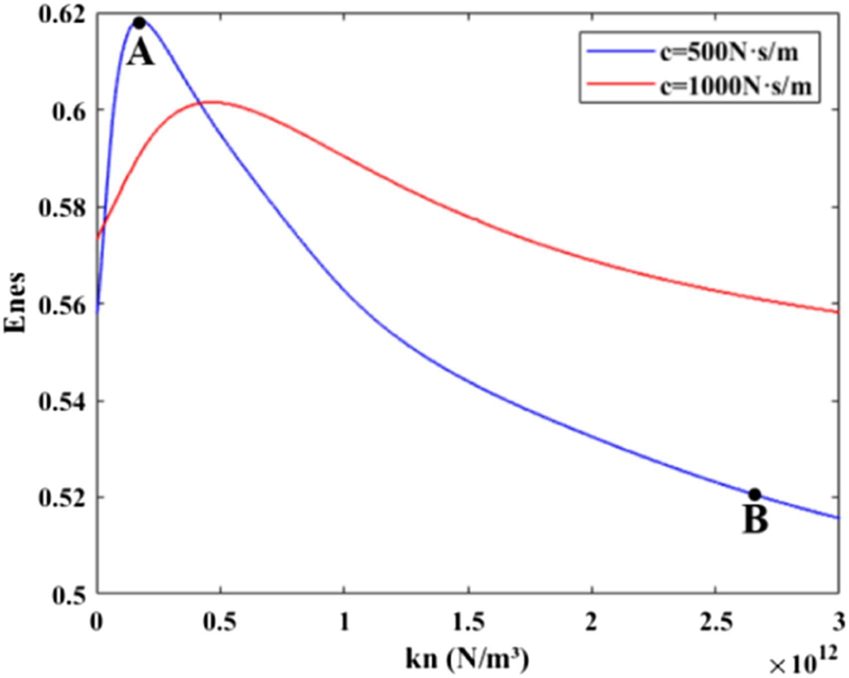
Comparing any of the constant velocity sections of the 3D plots in Figures 13 and 8, it can be seen that the transformation relationship of Enes with stiffness coefficient under different damping coefficients shows the same trend as that of the two-mass structure, that is, the NES has an optimal stiffness coefficient at a specific impact velocity.
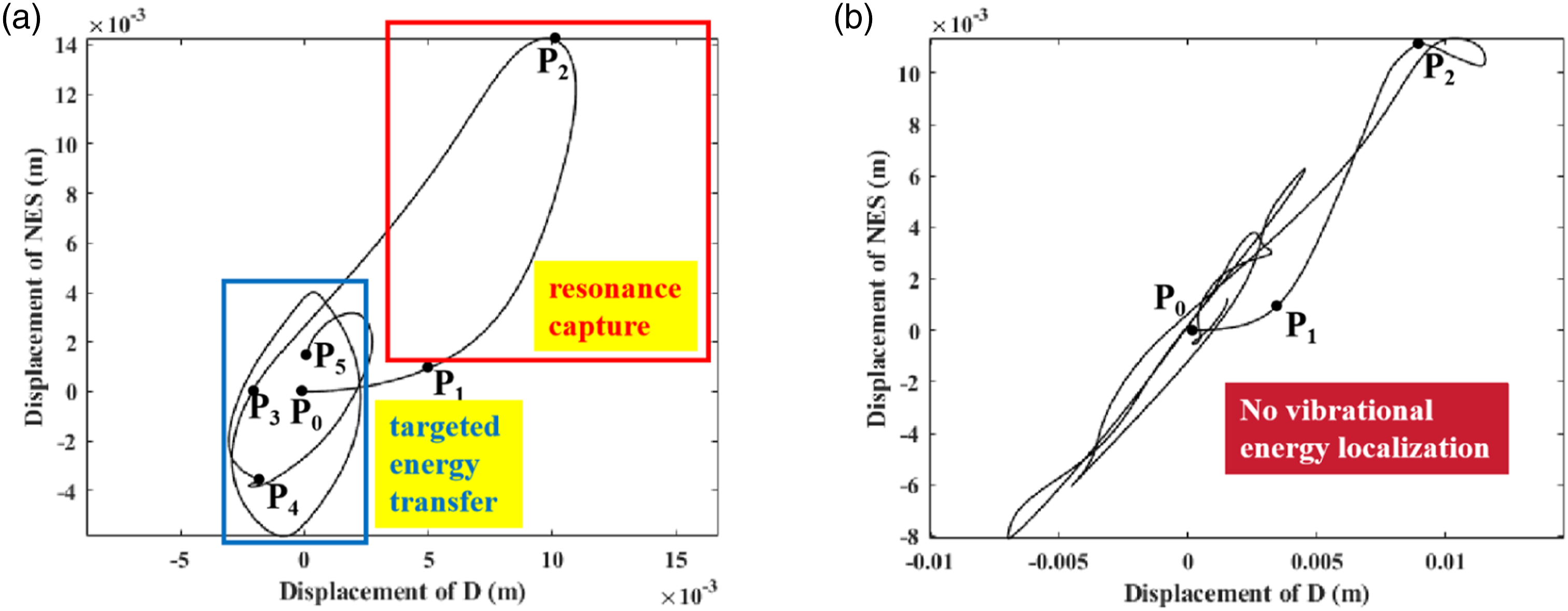
In addition, in order to further analyze the effects of different stiffness coefficients on the system dynamics characteristics, the results of the system dynamics response under the parameters of point A and point B in Figure 15 were selected and analyzed, respectively. Figure 16 shows the displacement response curves of the impact points D and NES, and Figure 17 shows the bitmap space curves of the impact points D and NES. Displacement Response Curve. (a)The parameters are those corresponding to point A, (b)The parameters are those corresponding to point B. Configuration space curve. (a)The parameters are those corresponding to point A, (b)The parameters are those corresponding to point B.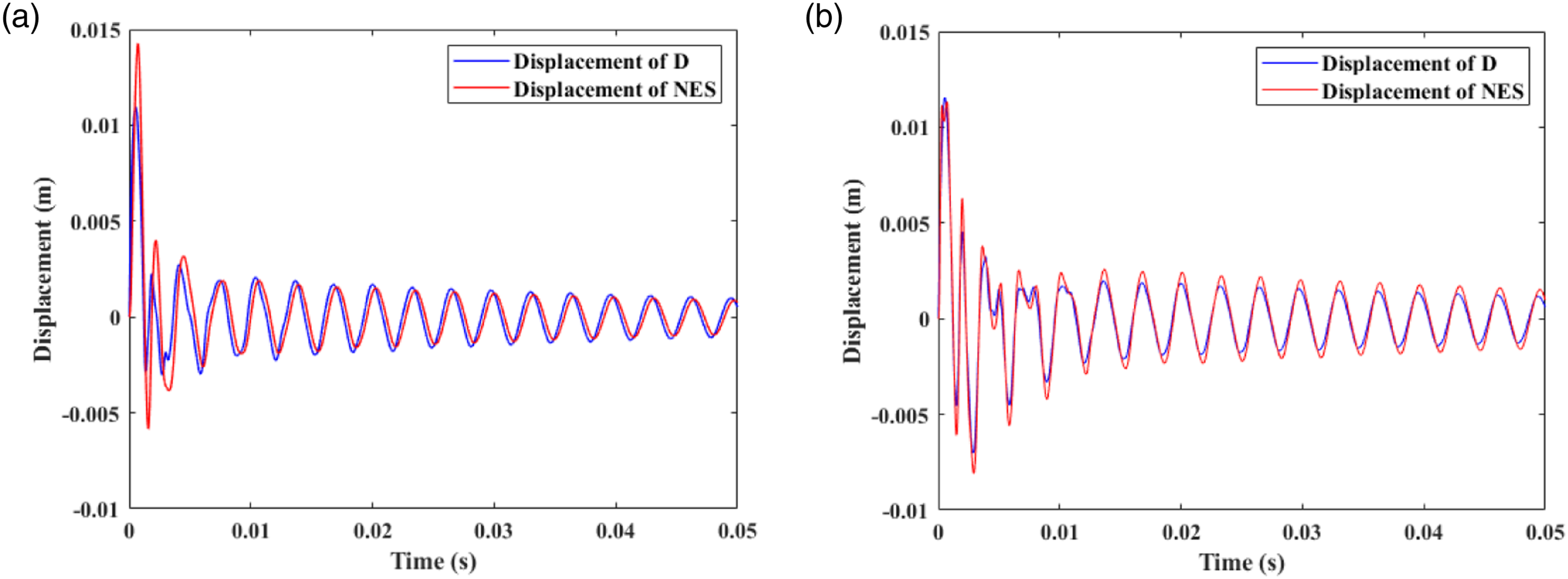
Comparing the response results in Figure 16, it can be found that when the system parameter is the parameter corresponding to point A, the displacement amplitude of the NES significantly exceeds that of point D in the initial stage, that is, energy localization at the NES is achieved, and the vibration energy is rapidly dissipated by the NES, which achieves the goal of rapid stabilization of point D (20% of the maximum amplitude after 0.002 s). Whereas, when the system parameters are those corresponding to point B, the displacement amplitude of the NES is close to point D, so the speed of stabilization at point D has to be greatly reduced (down to 20% of the highest amplitude after 0.002s).
Analyzing the structural bit pattern space curves under different parameters in Figure 17, it can be found that when the structural parameters are the parameters shown at point A in Figure 14, the system is mainly vibrating at point D and the NES is not activated when it receives the initial stage of the shock (P0P1 section), and then most of the vibration energy is transferred from point D to the NES (AB section). Subsequently, most of the vibration energy is transferred from point D to the NES, resulting in the phenomenon of vibration energy localization to the NES (segment P1P2). As the vibrational energy is dissipated, the localization of vibrational energy is destroyed, and the D-point and the NES move with approximately the same amplitude (P2P3 segment). As the vibrational energy is further dissipated, the localization of vibrational energy to the NES occurs again (segment P3P4). Finally, only a small portion of the vibration energy remains, and the D-point and the NES jointly vibrate to dissipate the energy. However, when the structural parameters are those shown at point B in Figure 14, the system behaves in the same way as before only in the initial time period, (P0P1 and P1P2 segments), and then the D-points and the NES vibrate with approximately the same amplitude until the system stabilizes.
To analyze the fast suppression effect of NES on the vibration of thin shells, the vibration response of thin shells containing NES structure and without NES structure under the impact action was calculated with an impact velocity of 50 m/s, and the results are shown in Figure 18. Vibration response curve when the system parameter is the corresponding parameter at point A.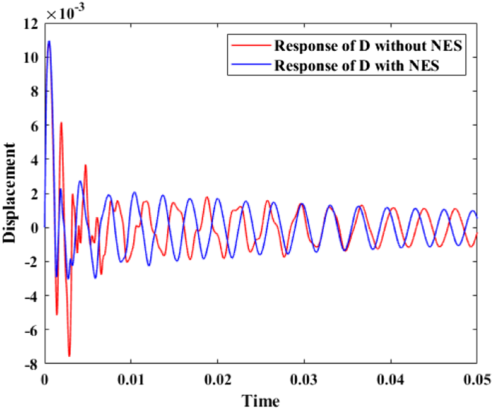
The analysis of Figure 18 shows that when the structural parameters are those shown at point A in Figure 14, when the vibration amplitude at point D is reduced to 20% of the maximum amplitude, it takes 0.007s for the structure with unattached NES and only 0.002s for the one with attached NES, which is a 71% reduction in time; the maximum displacement of the structure without NES is 0.008 m at the moment of impact, while that of the structure with NES is 0.003 m, which is a reduction of 62.5%; a significant reduction in the stabilization time of the structure under impact is achieved.
Conclusion
In this paper, the two-mass structure system was firstly dynamically analyzed, the frequency–energy diagram of the system was plotted, and the intrinsic mechanism of the occurrence of the targeted energy transfer was analyzed; the main dynamical characteristics of the system were calculated by using the method of averaging of the complex variables; and the effects of different parameters on the characteristics of the NES were calculated. Then the vibration suppression and fast stability performance of NES on thin-shell structures subjected to impact were calculated using the display dynamics method. The following conclusions were obtained: (1) NES has a start-up energy threshold, only when the impact energy exceeds the threshold, the system can realize the energy localization, NES can play a larger role in targeting vibration energy absorption; (2) NES has an optimal domain and this optimal domain is mainly related to the nonlinear stiffness, with the range of the optimal domain narrowing and the center value decreasing as the stiffness increases; (3) When the NES and the main system structure only 1:1 resonance, its performance of absorbing vibration energy is the best, when other orders of resonance, will reduce the performance of the NES; (4) When the thin-shell structure attached to the appropriate parameters of the NES, can significantly reduce its stabilization time after the impact action, the model studied in this paper in the mass of 1 kg, the speed of 50 m/s rigid body collision, the appropriate parameters of the NES can be made to stabilize the time shortened by 71%, the maximum displacement of the structure without NES is 0.008 m at the moment of impact, while that of the structure with NES is 0.003 m, which is a reduction of 62.5%.
Footnotes
Acknowledgments
The author(s) would like to thank them for funding it and for their permission to publish the paper.
Declaration of conflicting interests
The author(s) declared no potential conflicts of interest with respect to the research, authorship, and/or publication of this article.
Funding
The author(s) disclosed receipt of the following financial support for the research, authorship, and/or publication of this article: This work was supported by the National Science and Technology Major Project (J2019-III-0010-0054) and the State Key Program of National Natural Science Foundation of China (No. 52336002).
Data availability statement
The data that support the findings of this study are available from the corresponding author upon reasonable request.